EP2821196A1 - Paire de vis et extrudeuse à vis jumelées à engrenage co-rotatif prévu avec une paire de vis - Google Patents
Paire de vis et extrudeuse à vis jumelées à engrenage co-rotatif prévu avec une paire de vis Download PDFInfo
- Publication number
- EP2821196A1 EP2821196A1 EP13755712.0A EP13755712A EP2821196A1 EP 2821196 A1 EP2821196 A1 EP 2821196A1 EP 13755712 A EP13755712 A EP 13755712A EP 2821196 A1 EP2821196 A1 EP 2821196A1
- Authority
- EP
- European Patent Office
- Prior art keywords
- screw
- screws
- raw material
- groove
- synthetic resin
- Prior art date
- Legal status (The legal status is an assumption and is not a legal conclusion. Google has not performed a legal analysis and makes no representation as to the accuracy of the status listed.)
- Granted
Links
Images


Classifications
-
- B—PERFORMING OPERATIONS; TRANSPORTING
- B29—WORKING OF PLASTICS; WORKING OF SUBSTANCES IN A PLASTIC STATE IN GENERAL
- B29B—PREPARATION OR PRETREATMENT OF THE MATERIAL TO BE SHAPED; MAKING GRANULES OR PREFORMS; RECOVERY OF PLASTICS OR OTHER CONSTITUENTS OF WASTE MATERIAL CONTAINING PLASTICS
- B29B7/00—Mixing; Kneading
- B29B7/80—Component parts, details or accessories; Auxiliary operations
- B29B7/84—Venting or degassing ; Removing liquids, e.g. by evaporating components
- B29B7/842—Removing liquids in liquid form
-
- B—PERFORMING OPERATIONS; TRANSPORTING
- B29—WORKING OF PLASTICS; WORKING OF SUBSTANCES IN A PLASTIC STATE IN GENERAL
- B29B—PREPARATION OR PRETREATMENT OF THE MATERIAL TO BE SHAPED; MAKING GRANULES OR PREFORMS; RECOVERY OF PLASTICS OR OTHER CONSTITUENTS OF WASTE MATERIAL CONTAINING PLASTICS
- B29B7/00—Mixing; Kneading
- B29B7/30—Mixing; Kneading continuous, with mechanical mixing or kneading devices
- B29B7/34—Mixing; Kneading continuous, with mechanical mixing or kneading devices with movable mixing or kneading devices
- B29B7/38—Mixing; Kneading continuous, with mechanical mixing or kneading devices with movable mixing or kneading devices rotary
- B29B7/46—Mixing; Kneading continuous, with mechanical mixing or kneading devices with movable mixing or kneading devices rotary with more than one shaft
- B29B7/48—Mixing; Kneading continuous, with mechanical mixing or kneading devices with movable mixing or kneading devices rotary with more than one shaft with intermeshing devices, e.g. screws
-
- B—PERFORMING OPERATIONS; TRANSPORTING
- B29—WORKING OF PLASTICS; WORKING OF SUBSTANCES IN A PLASTIC STATE IN GENERAL
- B29B—PREPARATION OR PRETREATMENT OF THE MATERIAL TO BE SHAPED; MAKING GRANULES OR PREFORMS; RECOVERY OF PLASTICS OR OTHER CONSTITUENTS OF WASTE MATERIAL CONTAINING PLASTICS
- B29B7/00—Mixing; Kneading
- B29B7/30—Mixing; Kneading continuous, with mechanical mixing or kneading devices
- B29B7/34—Mixing; Kneading continuous, with mechanical mixing or kneading devices with movable mixing or kneading devices
- B29B7/38—Mixing; Kneading continuous, with mechanical mixing or kneading devices with movable mixing or kneading devices rotary
- B29B7/46—Mixing; Kneading continuous, with mechanical mixing or kneading devices with movable mixing or kneading devices rotary with more than one shaft
- B29B7/48—Mixing; Kneading continuous, with mechanical mixing or kneading devices with movable mixing or kneading devices rotary with more than one shaft with intermeshing devices, e.g. screws
- B29B7/482—Mixing; Kneading continuous, with mechanical mixing or kneading devices with movable mixing or kneading devices rotary with more than one shaft with intermeshing devices, e.g. screws provided with screw parts in addition to other mixing parts, e.g. paddles, gears, discs
-
- B—PERFORMING OPERATIONS; TRANSPORTING
- B29—WORKING OF PLASTICS; WORKING OF SUBSTANCES IN A PLASTIC STATE IN GENERAL
- B29B—PREPARATION OR PRETREATMENT OF THE MATERIAL TO BE SHAPED; MAKING GRANULES OR PREFORMS; RECOVERY OF PLASTICS OR OTHER CONSTITUENTS OF WASTE MATERIAL CONTAINING PLASTICS
- B29B7/00—Mixing; Kneading
- B29B7/30—Mixing; Kneading continuous, with mechanical mixing or kneading devices
- B29B7/34—Mixing; Kneading continuous, with mechanical mixing or kneading devices with movable mixing or kneading devices
- B29B7/38—Mixing; Kneading continuous, with mechanical mixing or kneading devices with movable mixing or kneading devices rotary
- B29B7/46—Mixing; Kneading continuous, with mechanical mixing or kneading devices with movable mixing or kneading devices rotary with more than one shaft
- B29B7/48—Mixing; Kneading continuous, with mechanical mixing or kneading devices with movable mixing or kneading devices rotary with more than one shaft with intermeshing devices, e.g. screws
- B29B7/482—Mixing; Kneading continuous, with mechanical mixing or kneading devices with movable mixing or kneading devices rotary with more than one shaft with intermeshing devices, e.g. screws provided with screw parts in addition to other mixing parts, e.g. paddles, gears, discs
- B29B7/483—Mixing; Kneading continuous, with mechanical mixing or kneading devices with movable mixing or kneading devices rotary with more than one shaft with intermeshing devices, e.g. screws provided with screw parts in addition to other mixing parts, e.g. paddles, gears, discs the other mixing parts being discs perpendicular to the screw axis
-
- B—PERFORMING OPERATIONS; TRANSPORTING
- B29—WORKING OF PLASTICS; WORKING OF SUBSTANCES IN A PLASTIC STATE IN GENERAL
- B29B—PREPARATION OR PRETREATMENT OF THE MATERIAL TO BE SHAPED; MAKING GRANULES OR PREFORMS; RECOVERY OF PLASTICS OR OTHER CONSTITUENTS OF WASTE MATERIAL CONTAINING PLASTICS
- B29B7/00—Mixing; Kneading
- B29B7/30—Mixing; Kneading continuous, with mechanical mixing or kneading devices
- B29B7/34—Mixing; Kneading continuous, with mechanical mixing or kneading devices with movable mixing or kneading devices
- B29B7/38—Mixing; Kneading continuous, with mechanical mixing or kneading devices with movable mixing or kneading devices rotary
- B29B7/46—Mixing; Kneading continuous, with mechanical mixing or kneading devices with movable mixing or kneading devices rotary with more than one shaft
- B29B7/48—Mixing; Kneading continuous, with mechanical mixing or kneading devices with movable mixing or kneading devices rotary with more than one shaft with intermeshing devices, e.g. screws
- B29B7/488—Parts, e.g. casings, sealings; Accessories, e.g. flow controlling or throttling devices
- B29B7/489—Screws
-
- B—PERFORMING OPERATIONS; TRANSPORTING
- B29—WORKING OF PLASTICS; WORKING OF SUBSTANCES IN A PLASTIC STATE IN GENERAL
- B29B—PREPARATION OR PRETREATMENT OF THE MATERIAL TO BE SHAPED; MAKING GRANULES OR PREFORMS; RECOVERY OF PLASTICS OR OTHER CONSTITUENTS OF WASTE MATERIAL CONTAINING PLASTICS
- B29B7/00—Mixing; Kneading
- B29B7/80—Component parts, details or accessories; Auxiliary operations
- B29B7/84—Venting or degassing ; Removing liquids, e.g. by evaporating components
-
- B—PERFORMING OPERATIONS; TRANSPORTING
- B29—WORKING OF PLASTICS; WORKING OF SUBSTANCES IN A PLASTIC STATE IN GENERAL
- B29B—PREPARATION OR PRETREATMENT OF THE MATERIAL TO BE SHAPED; MAKING GRANULES OR PREFORMS; RECOVERY OF PLASTICS OR OTHER CONSTITUENTS OF WASTE MATERIAL CONTAINING PLASTICS
- B29B7/00—Mixing; Kneading
- B29B7/80—Component parts, details or accessories; Auxiliary operations
- B29B7/84—Venting or degassing ; Removing liquids, e.g. by evaporating components
- B29B7/845—Venting, degassing or removing evaporated components in devices with rotary stirrers
-
- B—PERFORMING OPERATIONS; TRANSPORTING
- B29—WORKING OF PLASTICS; WORKING OF SUBSTANCES IN A PLASTIC STATE IN GENERAL
- B29C—SHAPING OR JOINING OF PLASTICS; SHAPING OF MATERIAL IN A PLASTIC STATE, NOT OTHERWISE PROVIDED FOR; AFTER-TREATMENT OF THE SHAPED PRODUCTS, e.g. REPAIRING
- B29C48/00—Extrusion moulding, i.e. expressing the moulding material through a die or nozzle which imparts the desired form; Apparatus therefor
- B29C48/25—Component parts, details or accessories; Auxiliary operations
- B29C48/36—Means for plasticising or homogenising the moulding material or forcing it through the nozzle or die
- B29C48/395—Means for plasticising or homogenising the moulding material or forcing it through the nozzle or die using screws surrounded by a cooperating barrel, e.g. single screw extruders
- B29C48/40—Means for plasticising or homogenising the moulding material or forcing it through the nozzle or die using screws surrounded by a cooperating barrel, e.g. single screw extruders using two or more parallel screws or at least two parallel non-intermeshing screws, e.g. twin screw extruders
- B29C48/405—Intermeshing co-rotating screws
-
- B—PERFORMING OPERATIONS; TRANSPORTING
- B29—WORKING OF PLASTICS; WORKING OF SUBSTANCES IN A PLASTIC STATE IN GENERAL
- B29C—SHAPING OR JOINING OF PLASTICS; SHAPING OF MATERIAL IN A PLASTIC STATE, NOT OTHERWISE PROVIDED FOR; AFTER-TREATMENT OF THE SHAPED PRODUCTS, e.g. REPAIRING
- B29C48/00—Extrusion moulding, i.e. expressing the moulding material through a die or nozzle which imparts the desired form; Apparatus therefor
- B29C48/25—Component parts, details or accessories; Auxiliary operations
- B29C48/36—Means for plasticising or homogenising the moulding material or forcing it through the nozzle or die
- B29C48/50—Details of extruders
- B29C48/76—Venting, drying means; Degassing means
- B29C48/765—Venting, drying means; Degassing means in the extruder apparatus
- B29C48/766—Venting, drying means; Degassing means in the extruder apparatus in screw extruders
- B29C48/767—Venting, drying means; Degassing means in the extruder apparatus in screw extruders through a degassing opening of a barrel
-
- B—PERFORMING OPERATIONS; TRANSPORTING
- B29—WORKING OF PLASTICS; WORKING OF SUBSTANCES IN A PLASTIC STATE IN GENERAL
- B29C—SHAPING OR JOINING OF PLASTICS; SHAPING OF MATERIAL IN A PLASTIC STATE, NOT OTHERWISE PROVIDED FOR; AFTER-TREATMENT OF THE SHAPED PRODUCTS, e.g. REPAIRING
- B29C48/00—Extrusion moulding, i.e. expressing the moulding material through a die or nozzle which imparts the desired form; Apparatus therefor
- B29C48/03—Extrusion moulding, i.e. expressing the moulding material through a die or nozzle which imparts the desired form; Apparatus therefor characterised by the shape of the extruded material at extrusion
-
- B—PERFORMING OPERATIONS; TRANSPORTING
- B29—WORKING OF PLASTICS; WORKING OF SUBSTANCES IN A PLASTIC STATE IN GENERAL
- B29C—SHAPING OR JOINING OF PLASTICS; SHAPING OF MATERIAL IN A PLASTIC STATE, NOT OTHERWISE PROVIDED FOR; AFTER-TREATMENT OF THE SHAPED PRODUCTS, e.g. REPAIRING
- B29C48/00—Extrusion moulding, i.e. expressing the moulding material through a die or nozzle which imparts the desired form; Apparatus therefor
- B29C48/25—Component parts, details or accessories; Auxiliary operations
- B29C48/268—Throttling of the flow, e.g. for cooperating with plasticising elements or for degassing
-
- B—PERFORMING OPERATIONS; TRANSPORTING
- B29—WORKING OF PLASTICS; WORKING OF SUBSTANCES IN A PLASTIC STATE IN GENERAL
- B29C—SHAPING OR JOINING OF PLASTICS; SHAPING OF MATERIAL IN A PLASTIC STATE, NOT OTHERWISE PROVIDED FOR; AFTER-TREATMENT OF THE SHAPED PRODUCTS, e.g. REPAIRING
- B29C48/00—Extrusion moulding, i.e. expressing the moulding material through a die or nozzle which imparts the desired form; Apparatus therefor
- B29C48/25—Component parts, details or accessories; Auxiliary operations
- B29C48/36—Means for plasticising or homogenising the moulding material or forcing it through the nozzle or die
- B29C48/395—Means for plasticising or homogenising the moulding material or forcing it through the nozzle or die using screws surrounded by a cooperating barrel, e.g. single screw extruders
- B29C48/40—Means for plasticising or homogenising the moulding material or forcing it through the nozzle or die using screws surrounded by a cooperating barrel, e.g. single screw extruders using two or more parallel screws or at least two parallel non-intermeshing screws, e.g. twin screw extruders
- B29C48/402—Means for plasticising or homogenising the moulding material or forcing it through the nozzle or die using screws surrounded by a cooperating barrel, e.g. single screw extruders using two or more parallel screws or at least two parallel non-intermeshing screws, e.g. twin screw extruders the screws having intermeshing parts
-
- B—PERFORMING OPERATIONS; TRANSPORTING
- B29—WORKING OF PLASTICS; WORKING OF SUBSTANCES IN A PLASTIC STATE IN GENERAL
- B29K—INDEXING SCHEME ASSOCIATED WITH SUBCLASSES B29B, B29C OR B29D, RELATING TO MOULDING MATERIALS OR TO MATERIALS FOR MOULDS, REINFORCEMENTS, FILLERS OR PREFORMED PARTS, e.g. INSERTS
- B29K2901/00—Use of unspecified macromolecular compounds as mould material
- B29K2901/12—Thermoplastic materials
Definitions
- the present invention relates to a screw pair for a co-rotating intermeshing type twin-screw extruder which removes a liquid component from a thermoplastic synthetic resin raw material containing a liquid component.
- thermoplastic synthetic resin raw material such as plastic or rubber containing a liquid component such as water
- the synthetic resin raw material is molded into a synthetic resin molding product after the liquid component is removed.
- a co-rotating intermeshing type twin-screw extruder hereinafter, referred to as simply an extruder
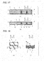
- Figs. 17(a) and 17(b) are an upper cross-sectional view and a side cross-sectional view showing an outline of a general extruder.
- an extruder 1 includes a cylinder 2 having a cylindrical shape, and a die 3 provided on one end of the cylinder 2.
- the cylinder 2 includes a raw material supply port 4 for inputting a synthetic resin raw material into the cylinder 2, and a liquid discharge port 5 for discharging a liquid component removed from the synthetic resin raw material from the inner portion of the cylinder 2.
- the extruder 1 includes a pair of screws 6 which is rotatably accommodated in the cylinder 2.
- the pair of screws 6 is disposed such that rotary axes R of the screws 6 are parallel with each other.
- Each screw 6 includes a transport portion 6a which transports the synthetic resin raw material in the cylinder 2 from a raw material supply port 4 in an X1 direction toward the die 3, and a throttling portion 6b which kneads the synthetic resin raw material and removes the liquid component from the synthetic resin raw material.
- the transport portion 6a and the throttling portion 6b are alternately disposed in the X1 direction, the synthetic resin raw material supplied from the raw material supply port 4 is transported to the throttling portion 6b by the transport portion 6a, passes through the throttling portion 6b, and is transported to the die 3.
- the liquid component of the synthetic resin raw material passes through the throttling portion 6b, the liquid component is removed from the synthetic resin raw material.
- the synthetic resin raw material, in which the liquid component is removed, is transported from the throttling portion 6b toward the die 3, and is extruded from the inner portion of the cylinder 2 while being molded to a predetermined shape by the die 3.
- the liquid component removed from the synthetic resin raw material flows through the transport portion 6a from the throttling portion 6b in an X2 direction opposite to the X1 direction.
- the liquid discharge port 5 is formed on the X2 direction side of the throttling portion 6b, and the liquid component removed from the synthetic resin raw material is discharged from the inner portion of the cylinder 2 through the liquid discharge port 5.
- a capability for transporting the synthetic resin raw material of the screw 6 in the X1 direction or a capability (hereinafter, also referred to as a draining capability) for causing the liquid component removed from the synthetic resin raw material to flow in the X2 direction
- a capability hereinafter, also referred to as a transportation capability
- a capability hereinafter, also referred to as a draining capability
- Fig. 18(a) is an outline view of a pair of angle flight screw pieces
- Fig. 18(b) is a cross-sectional view taken along line A-A of Fig. 18(a) .
- the angle flight screw piece 7 includes an outer circumferential surface 9 in which a groove 8 is spirally formed.
- a first surface 8a facing in the X1 direction and a second surface 8b facing in the X2 direction are erected to be approximately perpendicular with respect to an axis center of the angle flight screw piece 7 from a bottom surface 8c of the groove 8.
- the synthetic resin raw material input into the cylinder 2 enters the inner portion of the groove 8.
- the first surface 8a presses the synthetic resin raw material in the X1 direction.
- the synthetic resin raw material is transported in the X1 direction.
- the liquid component removed from the synthetic resin raw material flows in the X2 direction via a space in the groove 8 where the synthetic resin raw material is not present.
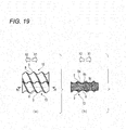
- Fig. 19(a) is an outline view of a pair of ball flight screw pieces
- Fig. 19(b) is a cross-sectional view taken along line B-B of Fig. 19(a) .
- the same reference numerals are assigned to the same components as those shown in Figs. 18(a) and 18(b) , and the components are simply described.
- the first and second surfaces 8a and 8b of one ball flight screw piece 10 and the outer circumferential surface 9 of the other ball flight screw piece 10 are curved to come into contact with each other. Accordingly, the pair of ball flight screw pieces 10 are rotated in the same direction, and the first and second surfaces 8a and 8b of the one ball flight screw piece 10 are in slide-contact with the outer circumferential surface 9 of the other ball flight screw piece 10.
- the outer circumferential surface 9 of the other ball flight screw piece 10 is in slide-contact with the first surface 8a of the one ball flight screw piece 10. Accordingly, the synthetic resin raw material adhering to the first surface 8a of the one ball flight screw piece 10 is scraped off.
- the other ball flight screw piece 10 also has a configuration similar to the one ball flight screw piece 10. That is, the pair of ball flight screw pieces 10 can transport the synthetic resin raw material without the adhesion of the synthetic resin raw material on the first surface 8a of each ball flight screw piece 10. Accordingly, in the ball flight screw pieces 10, a relatively high transportation capability can be obtained.
- a width in the X1 direction of the groove 8 of the ball flight screw piece 10 gradually decreases from an opening side of the groove 8 toward the bottom surface 8c of the groove 8. Accordingly, the volume of the groove 8 of the ball flight screw piece 10 is smaller than that of the groove 8 of the angle flight screw piece 7 shown in Figs. 18(a) and 18(b) . Therefore, in the ball flight screw piece 10, when a lot of synthetic resin raw materials are input into the cylinder 2 (refer to Figs. 17(a) and 17(b) ), the groove 8 is filled with the synthetic resin raw materials, the space though which the liquid component flows cannot be sufficiently secured, and there is a concern that the draining capability may be decreased.
- the liquid component removed from the synthetic resin raw material cannot be discharged by the throttling portion 6b (refer to Figs. 17(a) and 17(b) ), and the liquid component is input again to the synthetic resin raw material passing through the throttling portion 6b.
- the synthetic resin raw material extruded from the die 3 includes the liquid component, a defective product easily occurs when the synthetic resin molding product is molded.
- the present invention is made in consideration of the above problems, and an object thereof is to improve a draining capability of a screw without decreasing a transportation capability of the screw.
- a screw pair comprising: first and second screws for a co-rotating intermeshing type twin-screw extruder, the first and second screws having an outer circumferential surface on which a groove is spirally formed, wherein the first and second screws are configured to rotate about an axis center of each screw in a state where the first and second screws mesh with each other and to transport a raw material in a predetermined direction along the axis center, and wherein an inner surface of the groove of each of the first and second screws comprises: a first surface, which faces in the predetermined direction, and in which the outer circumferential surfaces of the first and second screws are formed to coincide with each other without a gap therebetween in the state where the first and second screws mesh with each other; and a second surface, which faces in a direction opposite to the predetermined direction, and which forms a gap between the outer circumferential surfaces of the first and second screws in the state where the first and second screws mesh with
- Fig. 1 is a side cross-sectional view showing an outline of an example of a co-rotating intermeshing type twin-screw extruder (hereinafter, referred to as an extruder) to which the present invention is applicable.
- Fig. 2 is a side cross-sectional view of an outline of another example of the extruder to which the present invention is applicable.
- a volatile component When a liquid component is removed from a synthetic resin raw material using the extruder, a volatile component may occur.
- a vent 11 for discharging the volatile component is formed on a cylinder 2.
- the extruder is referred to as a co-rotating intermeshing type twin-screw extruder having a vent (hereinafter, referred to as an extruder 12 having a vent).
- the vent is not provided on the cylinder 2.
- the extruder is referred to as a co-rotating intermeshing type twin-screw extruder without a vent (hereinafter, referred to as an extruder 13 without a vent).
- Whether or not the extruder 12 having a vent is used or the extruder 13 without a vent is used is determined by properties required for the synthetic resin raw material in which the liquid component is removed.
- the liquid component is removed from the synthetic resin raw material and the volatile component is discharged from the vent 11. Accordingly, in the extruder 12 having a vent, a synthetic resin raw material without including bubbles is obtained.
- the present invention can be applied to either the extruder 12 having a vent or the extruder 13 without a vent.
- the extruder 12 having a vent and the extruder 13 without a vent will not be distinguished from each other and will be described as an extruder.
- the extruder includes the cylinder 2, and a pair of screws 14 which is rotatably accommodated in the cylinder 2, and a die 3 which is provided at one end of the cylinder 2.
- the pair of screws 14 is disposed such that rotary axes R of the screws 14 are parallel with each other.
- Each screw 14 includes: a transport portion 15a configured to transport the synthetic resin raw material in the cylinder 2 in a predetermined direction (hereinafter, referred to as an X1 direction) from the raw material supply port 4 toward the die 3; and a throttling portion 15b configured to knead the synthetic resin raw material and remove the liquid component from the synthetic resin raw material.
- the transport portion 15a and the throttling portion 15b are alternately disposed in the X1 direction. Accordingly, the synthetic resin raw material, which is input from the raw material supply port 4 into the cylinder 2, is transported to the throttling portion 15b by the transport portion 15a, passes through the throttling portion 15b, and is transported to the die 3.
- a liquid discharge port 5 is formed on an X2 direction side opposite to the X1 direction of the throttling portion 15b in the cylinder 2.
- the liquid component which is removed from the synthetic resin raw material by the throttling portion 15b, flows through the transport portion 15a from the throttling portion 15b in the X2 direction, and is discharged from the liquid discharge port 5.
- the numbers of the liquid discharge ports 5 and the throttling portions 15b are not particularly limited. That is, one liquid discharge port 5 and one throttling portion 15b may be provided, and a plurality of liquid discharge ports 5 and a plurality of throttling portions 15b may be provided. If possible, preferably, the numbers of the liquid discharge ports 5 and the throttling portions 15b are optimized according to a content of the liquid component in the synthetic resin raw material input into the cylinder 2. This is because the manufacturing cost of the extruder is increased although the capability of removing the liquid component from the synthetic resin raw material is improved according to the increase of the numbers of the liquid discharge ports 5 and the throttling portions 15b.
- the numbers of the liquid discharge ports 5 and the throttling portions 15b are increased.
- one liquid discharge port 5 and one throttling portion 156 are provided.
- Figs. 3 and 4 are a photograph of an outline and a perspective view in a state where transport portions 15a of the pair of screws 14 mesh with each other.
- Fig. 5 is a side view of the transport portion 15a.
- Fig. 6 is a view for illustrating flows of a synthetic resin raw material and a liquid component in the transport portion 15a of the screw 14 shown in Fig. 5 .
- Fig. 7 is a cross-sectional view taken along line C-C of the screw 14 shown in Fig. 6 .
- the transport portion 15a of the screw 14 includes an outer circumferential surface 9 on which the groove 8 is spirally formed.
- the inner surface of the groove 8 includes: a first surface 8a facing in the X1 direction; and a second surface 8b facing in the X2 direction.
- first and second screws 14 mesh with each other such that a portion of the outer circumferential surface 9 of one screw 14 (hereinafter, referred to as a first screw 14a) enters a portion of the groove 8 of the other screw 14 (hereinafter, referred to as a second screw 14b).
- a synthetic resin raw material M input into the cylinder 2 enters the inner portion of the groove 8, and is transported in the X1 direction by the first surface 8a of the groove 8 according to the rotations of the first and second screws 14a and 14b.
- the first surface 8a of the first screw 14a is formed such that the outer circumferential surface 9 of the second screw 14b coincides with the first surface of the first screw without a gap therebetween in a state where the first and second screws 14a and 14b mesh with each other. Accordingly, when the first and second screws 14a and 14b are rotated in the same direction, the outer circumferential surface 9 of the second screw 14b is in slide-contact with the first surface 8a of the first screw 14a.
- the synthetic resin raw material M may adhere to the first surface 8a of the groove 8.
- the synthetic resin raw material M adhering to the first surface 8a of the first screw 14a is wiped away. Accordingly, the synthetic resin raw material M in the groove 8 of the first screw 14a is effectively transported, and the transportation capability of the first screw 14a is improved.
- the second surface 8b of the first screw 14a is erected from the bottom surface 8c of the groove 8 to be approximately parallel in a radial direction (which means a direction in which a virtual plane perpendicular to the axis center radially extends from the axis center) with the first screw 14a. Accordingly, compared with when the second surface 8b of the first screw 14a comes into contact with the outer circumferential surface 9 of the second screw 14b, a cross-sectional width in the X1 direction of the groove 8 of the first screw 14a can be increased. As a result, the volume of the groove 8 of the first screw 14a can be increased.
- the space in which the synthetic resin raw material M is not present in the groove 8 is increased as the volume of the groove 8 is increased, and thus, the liquid component W easily flows in the X2 direction in the transport portion 15a. As a result, a draining capability of the first screw 14a is improved.
- first and second surfaces 8a and 8b of the second screw 14b are also formed similar to the first and second surfaces 8a and 8b of the first screw 14a. Accordingly, the synthetic resin raw material M adhering to the first surface 8a of the second screw 14b is wiped away by the outer circumferential surface 9 of the first screw 14a. In addition, a cross-sectional width in the X1 direction of the groove 8 of the second screw 14b is relatively large, and the volume of the groove 8 of the second screw 14b is increased.
- Figs. 8(a) to 8(g) are cross-sectional views when cross sections perpendicular to the X1 direction of the first and second screws 14a and 14b meshing with each other are viewed in the X2 direction.
- Fig. 8(a) is a cross-sectional view at a predetermined timing
- Figs. 8(b) to 8(g) are cross-sectional views when the first and second screws 14a and 14b are rotated by 30°, 60°, 90°, 120°, 150°, and 180° from the state shown in Fig. 8(a) .
- the first and second surfaces 8a and 8b and the bottom surface 8c mean only the locations shown by the cross sections in Figs. 8(a) to 8(g)
- the outer circumferential surfaces 9 mean surfaces other than the inner surfaces of the grooves 8 among the locations shown by the cross sections in Figs. 8(a) to 8(g) .
- the first and second screws 14a and 14b have the above-described positional relationships.
- Fig. 9 is a cross-sectional view of a screw 16 according to another example of the present invention.
- the volume of the groove 8 of the screw 16 shown in Fig. 9 is larger than that of the groove 8 of each screw 14 shown in Figs. 8(a) to 8(g) . Accordingly, the draining capability of the screw 16 shown in Fig. 9 is further improved.
- the synthetic resin raw material M in the groove 8 is transported in the X1 direction by being pressed to the first surface 8a. That is, the synthetic resin raw material M does not substantially come into contact with the second surface 8b, and thus, the synthetic resin raw material M does not adhere to the second surface 8b. Accordingly, even when the second surface 8b of the first screw 14a is not in slide-contact with the outer circumferential surface 9 of the second screw 14b, the transportation capability of the first screw 14a is almost not decreased.
- FIG. 10 and 11 are a photograph and a perspective view of the outline in a state where transport portions of a pair of screws according to the comparative example mesh with each other.
- Fig. 12 is a side view of the transport portion.
- Fig. 13 is a view for illustrating flows of a synthetic resin raw material and a liquid component in the transport portion of the screw shown in Fig. 12 .
- Fig. 14 is a cross-sectional view taken along line D-D of the screw shown in Fig. 13 .
- the first and second surfaces 8a and 8b of the first screw 17a according to the comparative example are formed such that the outer circumferential surfaces 9 of the first and second screws 17a and 17b coincide with each other without a gap therebetween in the state where the first and second screws 17a and 17b mesh with each other. Accordingly, if the first and second screws 17a and 17b are rotated in the same direction, the outer circumferential surface 9 of the second screw 17b is in slide-contact with the first and second surfaces 8a and 8b of the first screw 17a.
- the volume of the groove 8 of the first screw 17a is smaller than that of the groove 8 of the first screw 14a according to the example.
- the second screw 17b according to the comparative example is also formed similar to the first screw 17a according to the comparative example, and the volume of the groove 8 of the second screw 17b according to the comparative example is smaller than that of the groove 8 of the second screw 17b according to the example.
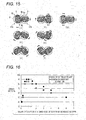
- Figs. 15(a) to 15(g) are cross-sectional views when cross sections perpendicular to the X1 direction of the first and second screws 17a and 17b meshing with each other are viewed in the X2 direction.
- Fig. 15(a) is a cross-sectional view at a predetermined timing
- Figs. 15(b) to 15(g) are cross-sectional views when the first and second screws 17a and 17b are rotated by 30°, 60°, 90°, 120°, 150°, and 180° from the state shown in Fig. 8(a) .
- the first and second surfaces 8a and 8b mean only the locations shown by the cross sections in Figs. 15(a) to 15(g)
- the outer circumferential surfaces 9 mean surfaces other than the inner surfaces of the grooves 8 among the locations shown by the cross sections in Figs. 15(a) to 15(g) .
- the first and second screws 17a and 17b have the above-described positional relationships.
- the screw 14 according to the example and the screw 17 according to the comparative example were applied to a co-rotating intermeshing type twin-screw extruder TEX65 manufactured by Japan Steel Works, Ltd., and thus, a comparative test of displacement was performed. Moreover, a diameter of the screw in the comparative test was set to 69 mm.
- Ethylene-Propylene-diene terpolymer Ethylene-Propylene-diene terpolymer (EPDM) was used.
- synthetic resin raw material input to the cylinder 2 (refer to Fig. 1 )
- synthetic resin raw material including 50% water in a proportion by weight was used as the synthetic resin raw material input to the cylinder 2 (refer to Fig. 1 ).
- An input amount into the cylinder 2 of the synthetic resin raw material containing water was set to 1000 kg/h, and a revolution speed of the screw was set 500 rpm.
- an amount of the discharged water is an amount of the water discharged from the liquid discharge port 5 (refer to Fig. 1 ), and an amount of the remaining water is an amount of the water included in the synthetic resin raw material extruded from the die 3 (refer to Fig. 1 ).
- a proportion of the discharged water is a value which is calculated by dividing the amount of the discharged water by the water amount included in the synthetic resin raw material before being input into the cylinder 2
- a proportion of the remaining water is a proportion by weight of the water included in the synthetic resin raw material extruded from the die 3.
- Fig. 16 is a graph showing the results of the comparative test in which a horizontal axis indicates a value obtained by dividing the lead of the screw by the screw diameter, and a vertical axis indicates a drain ratio.
- circular plots are the results for the screw 14 according to the example
- square plots are the results for the screw 17 according to the comparative example.
- the drain ratio in the screw 14 of the example is higher than the drain ratio in the screw 17 of the comparative example. From this, it is understood that the draining capability of the screw 14 is improved by using the screw 14 according to the example.
- the drain ratio of the screw 14 according to the example is far higher than the drain ratio of the screw 17 according to the comparative example. This is due to the following reasons.
- the value obtained by dividing the lead by the screw diameter is equal to or more than 0.5, and thus, the space, through which the water removed from the synthetic resin raw material flows, is sufficiently secured in the groove 8. Accordingly, the water removed from the synthetic resin raw material by the throttling portion 15b (refer to Fig. 1 ) is easily discharged.
- the value obtained by dividing the lead by the screw diameter is less than or equal to 3.0, and thus, a sufficient amount of synthetic resin raw material enters the groove 8, and the synthetic resin raw material is easily transported to the throttling portion 15b (refer to Fig. 1 ). Accordingly, the synthetic resin raw material is pressed to the throttling portion 15b by a stronger force, and more water is removed from the synthetic resin raw material in the throttling portion 15b.
- the drain ratio of the screw 14 according to the example is increased. Therefore, since more liquid component is removed from the synthetic resin raw material, it is preferable that the value obtained by dividing the lead of the screw 14 according to the example by the screw diameter be from 0.5 to 3.0.
- the present invention is not limited to the above-described embodiments, and modification, improvement, or the like can be appropriately performed. Moreover, the material, the shape, the dimensions, the value, the aspect, the number, the disposition place, or the like of each component in the above-described embodiments can arbitrarily be selected if they can achieve the present invention, and are not limited.
- the present invention including the effects is effectively used in the art of a co-rotating intermeshing type twin-screw extruder.
Landscapes
- Engineering & Computer Science (AREA)
- Mechanical Engineering (AREA)
- Extrusion Moulding Of Plastics Or The Like (AREA)
- Processing And Handling Of Plastics And Other Materials For Molding In General (AREA)
Applications Claiming Priority (2)
| Application Number | Priority Date | Filing Date | Title |
|---|---|---|---|
| JP2012045573A JP5562368B2 (ja) | 2012-03-01 | 2012-03-01 | スクリュ対および該スクリュ対を備えた同方向噛合型二軸スクリュ押出機 |
| PCT/JP2013/055520 WO2013129608A1 (fr) | 2012-03-01 | 2013-02-28 | Paire de vis et extrudeuse à vis jumelées à engrenage co-rotatif prévu avec une paire de vis |
Publications (3)
| Publication Number | Publication Date |
|---|---|
| EP2821196A1 true EP2821196A1 (fr) | 2015-01-07 |
| EP2821196A4 EP2821196A4 (fr) | 2015-10-14 |
| EP2821196B1 EP2821196B1 (fr) | 2020-03-25 |
Family
ID=49082799
Family Applications (1)
| Application Number | Title | Priority Date | Filing Date |
|---|---|---|---|
| EP13755712.0A Active EP2821196B1 (fr) | 2012-03-01 | 2013-02-28 | Extrudeuse à double vis à engrenage co-rotatif |
Country Status (7)
| Country | Link |
|---|---|
| US (1) | US9498899B2 (fr) |
| EP (1) | EP2821196B1 (fr) |
| JP (1) | JP5562368B2 (fr) |
| KR (1) | KR101528717B1 (fr) |
| CN (1) | CN104159718B (fr) |
| ES (1) | ES2785097T3 (fr) |
| WO (1) | WO2013129608A1 (fr) |
Families Citing this family (2)
| Publication number | Priority date | Publication date | Assignee | Title |
|---|---|---|---|---|
| US10792634B2 (en) * | 2015-07-31 | 2020-10-06 | Intel Corporation | Process for continuous granulation of powder material |
| CN105128306B (zh) * | 2015-08-28 | 2018-04-06 | 冯愚斌 | 单螺杆挤出机的一体式柔软薄片物料强制喂料装置及方法 |
Family Cites Families (25)
| Publication number | Priority date | Publication date | Assignee | Title |
|---|---|---|---|---|
| JPS61175428U (fr) * | 1985-04-22 | 1986-11-01 | ||
| US4752135A (en) * | 1986-12-01 | 1988-06-21 | Baker Perkins, Inc. | Mixing apparatus and methods |
| DE3738700A1 (de) * | 1987-11-14 | 1989-06-01 | Werner & Pfleiderer | Doppelschneckenextruder |
| JPH0479623U (fr) * | 1990-11-22 | 1992-07-10 | ||
| JPH0655612A (ja) * | 1992-08-04 | 1994-03-01 | Kobe Steel Ltd | 二軸押出機のスクリュー |
| JPH08210775A (ja) * | 1995-02-03 | 1996-08-20 | Hoshizaki Electric Co Ltd | 厨芥処理機 |
| JP3812964B2 (ja) * | 1995-10-20 | 2006-08-23 | 東芝機械株式会社 | 2軸押出機 |
| JP3434418B2 (ja) * | 1996-07-24 | 2003-08-11 | 東芝機械株式会社 | 同方向回転2軸押出機による高融点樹脂の脱水システム |
| JP3857411B2 (ja) * | 1998-03-27 | 2006-12-13 | 株式会社日本製鋼所 | 押出機のスクリュの搬送混練方法 |
| JP4176924B2 (ja) * | 1999-08-11 | 2008-11-05 | 旭化成ケミカルズ株式会社 | 熱可塑性樹脂の溶融混練方法 |
| JP4279976B2 (ja) * | 2000-05-16 | 2009-06-17 | 株式会社日本製鋼所 | 二軸脱水押出機による脱溶液方法および二軸脱水押出機 |
| JP4279975B2 (ja) * | 2000-05-16 | 2009-06-17 | 株式会社日本製鋼所 | 二軸脱水押出機による脱溶液方法および二軸脱水押出機 |
| DE10150006A1 (de) * | 2001-10-11 | 2003-04-17 | Buehler Ag | Ringextruder mit teilgekappten Förderelementen im Einzugsbereich |
| AT411663B (de) * | 2002-01-24 | 2004-04-26 | Cincinnati Extrusion Gmbh | Schneckenextruder |
| JP4150884B2 (ja) * | 2002-03-13 | 2008-09-17 | 日本ゼオン株式会社 | アロイの製造方法 |
| JP4217127B2 (ja) * | 2003-08-07 | 2009-01-28 | 住友ゴム工業株式会社 | 混練体の製造方法、及びそれに用いる装置 |
| ATE473088T1 (de) * | 2003-08-22 | 2010-07-15 | Coperion Gmbh | Schneckenmaschine mit misch- und knet-scheiben |
| WO2007033328A2 (fr) * | 2005-09-14 | 2007-03-22 | B & P Process Equipment And Systems, L.L.C. | Procede et appareil de formation d'un extrudat synthetique |
| JP2007326232A (ja) | 2006-06-06 | 2007-12-20 | Japan Steel Works Ltd:The | 二軸スクリュ式混練押出機 |
| CN201079735Y (zh) * | 2007-07-27 | 2008-07-02 | 重庆大学 | 差速双螺杆捏合机 |
| US20110067800A1 (en) | 2007-11-13 | 2011-03-24 | Pirelli Tyre S.P.A. | Process and plant for producing an elastomeric compound |
| US7635217B2 (en) * | 2008-01-03 | 2009-12-22 | Wenger Manufacturing, Inc. | Extruder having variable mid-barrel restriction and adjacent high intensity mixing assembly |
| DE102008029304A1 (de) * | 2008-06-20 | 2009-12-24 | Bayer Technology Services Gmbh | Verfahren zur Erzeugung von Schneckenelementen |
| US20110182133A1 (en) | 2008-09-29 | 2011-07-28 | Steer Engineering Private Limited | Extruder and method of extruder operation |
| EP2353839B1 (fr) * | 2010-01-27 | 2014-12-10 | Coperion GmbH | Procédé et installation pour dégazage polymères fondus |
-
2012
- 2012-03-01 JP JP2012045573A patent/JP5562368B2/ja active Active
-
2013
- 2013-02-28 EP EP13755712.0A patent/EP2821196B1/fr active Active
- 2013-02-28 US US14/382,247 patent/US9498899B2/en active Active
- 2013-02-28 ES ES13755712T patent/ES2785097T3/es active Active
- 2013-02-28 KR KR1020147027791A patent/KR101528717B1/ko active Active
- 2013-02-28 CN CN201380011988.5A patent/CN104159718B/zh active Active
- 2013-02-28 WO PCT/JP2013/055520 patent/WO2013129608A1/fr not_active Ceased
Also Published As
| Publication number | Publication date |
|---|---|
| ES2785097T3 (es) | 2020-10-05 |
| KR101528717B1 (ko) | 2015-06-16 |
| CN104159718A (zh) | 2014-11-19 |
| WO2013129608A1 (fr) | 2013-09-06 |
| CN104159718B (zh) | 2017-09-26 |
| US9498899B2 (en) | 2016-11-22 |
| US20150029812A1 (en) | 2015-01-29 |
| KR20140131389A (ko) | 2014-11-12 |
| EP2821196B1 (fr) | 2020-03-25 |
| JP5562368B2 (ja) | 2014-07-30 |
| EP2821196A4 (fr) | 2015-10-14 |
| JP2013180483A (ja) | 2013-09-12 |
Similar Documents
| Publication | Publication Date | Title |
|---|---|---|
| EP2168743B1 (fr) | Extrudeuse de fusion-malaxage a devolatilisation | |
| KR101715461B1 (ko) | 자체-클리닝 컨베이어 스크류를 갖는 다중 스크류 압출기 | |
| US8753003B2 (en) | Screw feed elements for extrusion of viscoelastic masses | |
| JP5031723B2 (ja) | 押出機 | |
| EP4074482B1 (fr) | Vis, extrudeuse et procédé d'extrusion | |
| EP2821196B1 (fr) | Extrudeuse à double vis à engrenage co-rotatif | |
| US20110133355A1 (en) | Extruder Having Dual Mixing Stages And Process For Preparing A Mixture Of Polymer And Diluent | |
| CN106863748A (zh) | 挤压机 | |
| US8770824B2 (en) | Extruder and process for preparing a mixture of polymer and diluent | |
| CN103770231B (zh) | 一种双向拉伸形变协同作用的混合方法及装置 | |
| CA2644925C (fr) | Element helicoidal | |
| US11376760B2 (en) | Kneading disc having band portion with bent part, screw element and extruder | |
| US20060269640A1 (en) | Screw-type kneading /extruding machine | |
| CN211279618U (zh) | 一种拉伸孔混炼元件 | |
| US8998481B2 (en) | Double screw extruder | |
| US11027475B2 (en) | Screw-type extruder | |
| CN102463666B (zh) | 一种用于双螺杆挤出机的啮合盘元件及双螺杆挤出机 | |
| CN203739042U (zh) | 一种双向拉伸形变协同作用的混合装置 | |
| KR20250031020A (ko) | 혼련성 향상을 위한 스크류가 구비된 이축 압출기 | |
| CN202212119U (zh) | 转子一字型排列的三转子连续混炼机组 | |
| CN114450140B (zh) | 在脱气口区域中包括具有特别高螺距的螺杆元件的挤出机及其用途 | |
| CN100496928C (zh) | 组合式变间隙转子 | |
| CN106217818A (zh) | 一种具有动态连续密炼功能的锥形双螺杆挤出机 | |
| KR20180099374A (ko) | 탈휘 압출기 | |
| JP2006341489A (ja) | 連続混練装置 |
Legal Events
| Date | Code | Title | Description |
|---|---|---|---|
| PUAI | Public reference made under article 153(3) epc to a published international application that has entered the european phase |
Free format text: ORIGINAL CODE: 0009012 |
|
| 17P | Request for examination filed |
Effective date: 20140901 |
|
| AK | Designated contracting states |
Kind code of ref document: A1 Designated state(s): AL AT BE BG CH CY CZ DE DK EE ES FI FR GB GR HR HU IE IS IT LI LT LU LV MC MK MT NL NO PL PT RO RS SE SI SK SM TR |
|
| AX | Request for extension of the european patent |
Extension state: BA ME |
|
| DAX | Request for extension of the european patent (deleted) | ||
| RA4 | Supplementary search report drawn up and despatched (corrected) |
Effective date: 20150915 |
|
| RIC1 | Information provided on ipc code assigned before grant |
Ipc: B29C 47/76 20060101ALI20150909BHEP Ipc: B29B 7/84 20060101ALN20150909BHEP Ipc: B29B 7/48 20060101ALN20150909BHEP Ipc: B29C 47/40 20060101AFI20150909BHEP Ipc: B29B 7/46 20060101ALN20150909BHEP Ipc: B29C 47/60 20060101ALI20150909BHEP |
|
| STAA | Information on the status of an ep patent application or granted ep patent |
Free format text: STATUS: EXAMINATION IS IN PROGRESS |
|
| 17Q | First examination report despatched |
Effective date: 20180803 |
|
| REG | Reference to a national code |
Ref country code: DE Ref legal event code: R079 Ref document number: 602013067175 Country of ref document: DE Free format text: PREVIOUS MAIN CLASS: B29B0007460000 Ipc: B29C0048405000 |
|
| GRAP | Despatch of communication of intention to grant a patent |
Free format text: ORIGINAL CODE: EPIDOSNIGR1 |
|
| STAA | Information on the status of an ep patent application or granted ep patent |
Free format text: STATUS: GRANT OF PATENT IS INTENDED |
|
| RIC1 | Information provided on ipc code assigned before grant |
Ipc: B29B 7/84 20060101ALN20191011BHEP Ipc: B29B 7/46 20060101ALN20191011BHEP Ipc: B29C 48/76 20190101ALI20191011BHEP Ipc: B29C 48/405 20190101AFI20191011BHEP Ipc: B29C 48/60 20190101ALI20191011BHEP Ipc: B29B 7/48 20060101ALN20191011BHEP |
|
| INTG | Intention to grant announced |
Effective date: 20191031 |
|
| RIN1 | Information on inventor provided before grant (corrected) |
Inventor name: HANDA, KIYOSHI Inventor name: KAKIZAKI, JUN Inventor name: SHIMIZU, YOHEI |
|
| GRAS | Grant fee paid |
Free format text: ORIGINAL CODE: EPIDOSNIGR3 |
|
| GRAA | (expected) grant |
Free format text: ORIGINAL CODE: 0009210 |
|
| STAA | Information on the status of an ep patent application or granted ep patent |
Free format text: STATUS: THE PATENT HAS BEEN GRANTED |
|
| AK | Designated contracting states |
Kind code of ref document: B1 Designated state(s): AL AT BE BG CH CY CZ DE DK EE ES FI FR GB GR HR HU IE IS IT LI LT LU LV MC MK MT NL NO PL PT RO RS SE SI SK SM TR |
|
| REG | Reference to a national code |
Ref country code: GB Ref legal event code: FG4D |
|
| REG | Reference to a national code |
Ref country code: AT Ref legal event code: REF Ref document number: 1248070 Country of ref document: AT Kind code of ref document: T Effective date: 20200415 Ref country code: IE Ref legal event code: FG4D |
|
| REG | Reference to a national code |
Ref country code: DE Ref legal event code: R096 Ref document number: 602013067175 Country of ref document: DE |
|
| REG | Reference to a national code |
Ref country code: NL Ref legal event code: FP |
|
| PG25 | Lapsed in a contracting state [announced via postgrant information from national office to epo] |
Ref country code: FI Free format text: LAPSE BECAUSE OF FAILURE TO SUBMIT A TRANSLATION OF THE DESCRIPTION OR TO PAY THE FEE WITHIN THE PRESCRIBED TIME-LIMIT Effective date: 20200325 Ref country code: NO Free format text: LAPSE BECAUSE OF FAILURE TO SUBMIT A TRANSLATION OF THE DESCRIPTION OR TO PAY THE FEE WITHIN THE PRESCRIBED TIME-LIMIT Effective date: 20200625 Ref country code: RS Free format text: LAPSE BECAUSE OF FAILURE TO SUBMIT A TRANSLATION OF THE DESCRIPTION OR TO PAY THE FEE WITHIN THE PRESCRIBED TIME-LIMIT Effective date: 20200325 |
|
| PG25 | Lapsed in a contracting state [announced via postgrant information from national office to epo] |
Ref country code: GR Free format text: LAPSE BECAUSE OF FAILURE TO SUBMIT A TRANSLATION OF THE DESCRIPTION OR TO PAY THE FEE WITHIN THE PRESCRIBED TIME-LIMIT Effective date: 20200626 Ref country code: LV Free format text: LAPSE BECAUSE OF FAILURE TO SUBMIT A TRANSLATION OF THE DESCRIPTION OR TO PAY THE FEE WITHIN THE PRESCRIBED TIME-LIMIT Effective date: 20200325 Ref country code: SE Free format text: LAPSE BECAUSE OF FAILURE TO SUBMIT A TRANSLATION OF THE DESCRIPTION OR TO PAY THE FEE WITHIN THE PRESCRIBED TIME-LIMIT Effective date: 20200325 Ref country code: HR Free format text: LAPSE BECAUSE OF FAILURE TO SUBMIT A TRANSLATION OF THE DESCRIPTION OR TO PAY THE FEE WITHIN THE PRESCRIBED TIME-LIMIT Effective date: 20200325 Ref country code: BG Free format text: LAPSE BECAUSE OF FAILURE TO SUBMIT A TRANSLATION OF THE DESCRIPTION OR TO PAY THE FEE WITHIN THE PRESCRIBED TIME-LIMIT Effective date: 20200625 |
|
| REG | Reference to a national code |
Ref country code: LT Ref legal event code: MG4D |
|
| REG | Reference to a national code |
Ref country code: ES Ref legal event code: FG2A Ref document number: 2785097 Country of ref document: ES Kind code of ref document: T3 Effective date: 20201005 |
|
| PG25 | Lapsed in a contracting state [announced via postgrant information from national office to epo] |
Ref country code: CZ Free format text: LAPSE BECAUSE OF FAILURE TO SUBMIT A TRANSLATION OF THE DESCRIPTION OR TO PAY THE FEE WITHIN THE PRESCRIBED TIME-LIMIT Effective date: 20200325 Ref country code: LT Free format text: LAPSE BECAUSE OF FAILURE TO SUBMIT A TRANSLATION OF THE DESCRIPTION OR TO PAY THE FEE WITHIN THE PRESCRIBED TIME-LIMIT Effective date: 20200325 Ref country code: RO Free format text: LAPSE BECAUSE OF FAILURE TO SUBMIT A TRANSLATION OF THE DESCRIPTION OR TO PAY THE FEE WITHIN THE PRESCRIBED TIME-LIMIT Effective date: 20200325 Ref country code: IS Free format text: LAPSE BECAUSE OF FAILURE TO SUBMIT A TRANSLATION OF THE DESCRIPTION OR TO PAY THE FEE WITHIN THE PRESCRIBED TIME-LIMIT Effective date: 20200725 Ref country code: SK Free format text: LAPSE BECAUSE OF FAILURE TO SUBMIT A TRANSLATION OF THE DESCRIPTION OR TO PAY THE FEE WITHIN THE PRESCRIBED TIME-LIMIT Effective date: 20200325 Ref country code: SM Free format text: LAPSE BECAUSE OF FAILURE TO SUBMIT A TRANSLATION OF THE DESCRIPTION OR TO PAY THE FEE WITHIN THE PRESCRIBED TIME-LIMIT Effective date: 20200325 Ref country code: EE Free format text: LAPSE BECAUSE OF FAILURE TO SUBMIT A TRANSLATION OF THE DESCRIPTION OR TO PAY THE FEE WITHIN THE PRESCRIBED TIME-LIMIT Effective date: 20200325 Ref country code: PT Free format text: LAPSE BECAUSE OF FAILURE TO SUBMIT A TRANSLATION OF THE DESCRIPTION OR TO PAY THE FEE WITHIN THE PRESCRIBED TIME-LIMIT Effective date: 20200818 |
|
| REG | Reference to a national code |
Ref country code: AT Ref legal event code: MK05 Ref document number: 1248070 Country of ref document: AT Kind code of ref document: T Effective date: 20200325 |
|
| REG | Reference to a national code |
Ref country code: DE Ref legal event code: R097 Ref document number: 602013067175 Country of ref document: DE |
|
| PG25 | Lapsed in a contracting state [announced via postgrant information from national office to epo] |
Ref country code: DK Free format text: LAPSE BECAUSE OF FAILURE TO SUBMIT A TRANSLATION OF THE DESCRIPTION OR TO PAY THE FEE WITHIN THE PRESCRIBED TIME-LIMIT Effective date: 20200325 Ref country code: AT Free format text: LAPSE BECAUSE OF FAILURE TO SUBMIT A TRANSLATION OF THE DESCRIPTION OR TO PAY THE FEE WITHIN THE PRESCRIBED TIME-LIMIT Effective date: 20200325 |
|
| PLBE | No opposition filed within time limit |
Free format text: ORIGINAL CODE: 0009261 |
|
| STAA | Information on the status of an ep patent application or granted ep patent |
Free format text: STATUS: NO OPPOSITION FILED WITHIN TIME LIMIT |
|
| PG25 | Lapsed in a contracting state [announced via postgrant information from national office to epo] |
Ref country code: PL Free format text: LAPSE BECAUSE OF FAILURE TO SUBMIT A TRANSLATION OF THE DESCRIPTION OR TO PAY THE FEE WITHIN THE PRESCRIBED TIME-LIMIT Effective date: 20200325 |
|
| 26N | No opposition filed |
Effective date: 20210112 |
|
| PG25 | Lapsed in a contracting state [announced via postgrant information from national office to epo] |
Ref country code: SI Free format text: LAPSE BECAUSE OF FAILURE TO SUBMIT A TRANSLATION OF THE DESCRIPTION OR TO PAY THE FEE WITHIN THE PRESCRIBED TIME-LIMIT Effective date: 20200325 |
|
| PG25 | Lapsed in a contracting state [announced via postgrant information from national office to epo] |
Ref country code: MC Free format text: LAPSE BECAUSE OF FAILURE TO SUBMIT A TRANSLATION OF THE DESCRIPTION OR TO PAY THE FEE WITHIN THE PRESCRIBED TIME-LIMIT Effective date: 20200325 |
|
| PG25 | Lapsed in a contracting state [announced via postgrant information from national office to epo] |
Ref country code: CH Free format text: LAPSE BECAUSE OF NON-PAYMENT OF DUE FEES Effective date: 20210228 Ref country code: LU Free format text: LAPSE BECAUSE OF NON-PAYMENT OF DUE FEES Effective date: 20210228 Ref country code: LI Free format text: LAPSE BECAUSE OF NON-PAYMENT OF DUE FEES Effective date: 20210228 |
|
| PG25 | Lapsed in a contracting state [announced via postgrant information from national office to epo] |
Ref country code: IE Free format text: LAPSE BECAUSE OF NON-PAYMENT OF DUE FEES Effective date: 20210228 |
|
| PG25 | Lapsed in a contracting state [announced via postgrant information from national office to epo] |
Ref country code: HU Free format text: LAPSE BECAUSE OF FAILURE TO SUBMIT A TRANSLATION OF THE DESCRIPTION OR TO PAY THE FEE WITHIN THE PRESCRIBED TIME-LIMIT; INVALID AB INITIO Effective date: 20130228 |
|
| P01 | Opt-out of the competence of the unified patent court (upc) registered |
Effective date: 20230515 |
|
| PG25 | Lapsed in a contracting state [announced via postgrant information from national office to epo] |
Ref country code: CY Free format text: LAPSE BECAUSE OF FAILURE TO SUBMIT A TRANSLATION OF THE DESCRIPTION OR TO PAY THE FEE WITHIN THE PRESCRIBED TIME-LIMIT Effective date: 20200325 |
|
| PGFP | Annual fee paid to national office [announced via postgrant information from national office to epo] |
Ref country code: NL Payment date: 20240108 Year of fee payment: 12 |
|
| PGFP | Annual fee paid to national office [announced via postgrant information from national office to epo] |
Ref country code: ES Payment date: 20240304 Year of fee payment: 12 |
|
| PG25 | Lapsed in a contracting state [announced via postgrant information from national office to epo] |
Ref country code: MK Free format text: LAPSE BECAUSE OF FAILURE TO SUBMIT A TRANSLATION OF THE DESCRIPTION OR TO PAY THE FEE WITHIN THE PRESCRIBED TIME-LIMIT Effective date: 20200325 |
|
| PGFP | Annual fee paid to national office [announced via postgrant information from national office to epo] |
Ref country code: GB Payment date: 20240109 Year of fee payment: 12 |
|
| PGFP | Annual fee paid to national office [announced via postgrant information from national office to epo] |
Ref country code: IT Payment date: 20240111 Year of fee payment: 12 Ref country code: FR Payment date: 20240103 Year of fee payment: 12 Ref country code: BE Payment date: 20240105 Year of fee payment: 12 |
|
| PG25 | Lapsed in a contracting state [announced via postgrant information from national office to epo] |
Ref country code: MT Free format text: LAPSE BECAUSE OF FAILURE TO SUBMIT A TRANSLATION OF THE DESCRIPTION OR TO PAY THE FEE WITHIN THE PRESCRIBED TIME-LIMIT Effective date: 20200325 |
|
| REG | Reference to a national code |
Ref country code: NL Ref legal event code: MM Effective date: 20250301 |
|
| GBPC | Gb: european patent ceased through non-payment of renewal fee |
Effective date: 20250228 |
|
| PG25 | Lapsed in a contracting state [announced via postgrant information from national office to epo] |
Ref country code: NL Free format text: LAPSE BECAUSE OF NON-PAYMENT OF DUE FEES Effective date: 20250301 |
|
| REG | Reference to a national code |
Ref country code: BE Ref legal event code: MM Effective date: 20250228 |
|
| PG25 | Lapsed in a contracting state [announced via postgrant information from national office to epo] |
Ref country code: TR Free format text: LAPSE BECAUSE OF FAILURE TO SUBMIT A TRANSLATION OF THE DESCRIPTION OR TO PAY THE FEE WITHIN THE PRESCRIBED TIME-LIMIT Effective date: 20200325 |
|
| PG25 | Lapsed in a contracting state [announced via postgrant information from national office to epo] |
Ref country code: GB Free format text: LAPSE BECAUSE OF NON-PAYMENT OF DUE FEES Effective date: 20250228 |
|
| PG25 | Lapsed in a contracting state [announced via postgrant information from national office to epo] |
Ref country code: FR Free format text: LAPSE BECAUSE OF NON-PAYMENT OF DUE FEES Effective date: 20250228 Ref country code: IT Free format text: LAPSE BECAUSE OF NON-PAYMENT OF DUE FEES Effective date: 20250228 |
|
| PG25 | Lapsed in a contracting state [announced via postgrant information from national office to epo] |
Ref country code: BE Free format text: LAPSE BECAUSE OF NON-PAYMENT OF DUE FEES Effective date: 20250228 |
|
| REG | Reference to a national code |
Ref country code: ES Ref legal event code: FD2A Effective date: 20260407 |
|
| PG25 | Lapsed in a contracting state [announced via postgrant information from national office to epo] |
Ref country code: ES Free format text: LAPSE BECAUSE OF NON-PAYMENT OF DUE FEES Effective date: 20250301 |
|
| PGFP | Annual fee paid to national office [announced via postgrant information from national office to epo] |
Ref country code: DE Payment date: 20260102 Year of fee payment: 14 |