EP2821302B1 - Système de commande de frein comprenant un mappage d'évaluation de la propriété de frottement de pneu/piste - Google Patents
Système de commande de frein comprenant un mappage d'évaluation de la propriété de frottement de pneu/piste Download PDFInfo
- Publication number
- EP2821302B1 EP2821302B1 EP14171610.0A EP14171610A EP2821302B1 EP 2821302 B1 EP2821302 B1 EP 2821302B1 EP 14171610 A EP14171610 A EP 14171610A EP 2821302 B1 EP2821302 B1 EP 2821302B1
- Authority
- EP
- European Patent Office
- Prior art keywords
- wheel
- runway
- aircraft
- brake control
- tire
- Prior art date
- Legal status (The legal status is an assumption and is not a legal conclusion. Google has not performed a legal analysis and makes no representation as to the accuracy of the status listed.)
- Active
Links
Images



Classifications
-
- B—PERFORMING OPERATIONS; TRANSPORTING
- B60—VEHICLES IN GENERAL
- B60T—VEHICLE BRAKE CONTROL SYSTEMS OR PARTS THEREOF; BRAKE CONTROL SYSTEMS OR PARTS THEREOF, IN GENERAL; ARRANGEMENT OF BRAKING ELEMENTS ON VEHICLES IN GENERAL; PORTABLE DEVICES FOR PREVENTING UNWANTED MOVEMENT OF VEHICLES; VEHICLE MODIFICATIONS TO FACILITATE COOLING OF BRAKES
- B60T8/00—Arrangements for adjusting wheel-braking force to meet varying vehicular or ground-surface conditions, e.g. limiting or varying distribution of braking force
- B60T8/17—Using electrical or electronic regulation means to control braking
- B60T8/171—Detecting parameters used in the regulation; Measuring values used in the regulation
-
- B—PERFORMING OPERATIONS; TRANSPORTING
- B60—VEHICLES IN GENERAL
- B60T—VEHICLE BRAKE CONTROL SYSTEMS OR PARTS THEREOF; BRAKE CONTROL SYSTEMS OR PARTS THEREOF, IN GENERAL; ARRANGEMENT OF BRAKING ELEMENTS ON VEHICLES IN GENERAL; PORTABLE DEVICES FOR PREVENTING UNWANTED MOVEMENT OF VEHICLES; VEHICLE MODIFICATIONS TO FACILITATE COOLING OF BRAKES
- B60T8/00—Arrangements for adjusting wheel-braking force to meet varying vehicular or ground-surface conditions, e.g. limiting or varying distribution of braking force
- B60T8/17—Using electrical or electronic regulation means to control braking
- B60T8/1701—Braking or traction control means specially adapted for particular types of vehicles
- B60T8/1703—Braking or traction control means specially adapted for particular types of vehicles for aircrafts
-
- B—PERFORMING OPERATIONS; TRANSPORTING
- B60—VEHICLES IN GENERAL
- B60T—VEHICLE BRAKE CONTROL SYSTEMS OR PARTS THEREOF; BRAKE CONTROL SYSTEMS OR PARTS THEREOF, IN GENERAL; ARRANGEMENT OF BRAKING ELEMENTS ON VEHICLES IN GENERAL; PORTABLE DEVICES FOR PREVENTING UNWANTED MOVEMENT OF VEHICLES; VEHICLE MODIFICATIONS TO FACILITATE COOLING OF BRAKES
- B60T8/00—Arrangements for adjusting wheel-braking force to meet varying vehicular or ground-surface conditions, e.g. limiting or varying distribution of braking force
- B60T8/17—Using electrical or electronic regulation means to control braking
- B60T8/172—Determining control parameters used in the regulation, e.g. by calculations involving measured or detected parameters
-
- B—PERFORMING OPERATIONS; TRANSPORTING
- B64—AIRCRAFT; AVIATION; COSMONAUTICS
- B64C—AEROPLANES; HELICOPTERS
- B64C25/00—Alighting gear
- B64C25/32—Alighting gear characterised by elements which contact the ground or similar surface
- B64C25/42—Arrangement or adaptation of brakes
- B64C25/44—Actuating mechanisms
- B64C25/46—Brake regulators for preventing skidding or aircraft somersaulting
-
- G—PHYSICS
- G01—MEASURING; TESTING
- G01L—MEASURING FORCE, STRESS, TORQUE, WORK, MECHANICAL POWER, MECHANICAL EFFICIENCY, OR FLUID PRESSURE
- G01L5/00—Apparatus for, or methods of, measuring force, work, mechanical power, or torque, specially adapted for specific purposes
- G01L5/28—Apparatus for, or methods of, measuring force, work, mechanical power, or torque, specially adapted for specific purposes for testing brakes
-
- B—PERFORMING OPERATIONS; TRANSPORTING
- B60—VEHICLES IN GENERAL
- B60T—VEHICLE BRAKE CONTROL SYSTEMS OR PARTS THEREOF; BRAKE CONTROL SYSTEMS OR PARTS THEREOF, IN GENERAL; ARRANGEMENT OF BRAKING ELEMENTS ON VEHICLES IN GENERAL; PORTABLE DEVICES FOR PREVENTING UNWANTED MOVEMENT OF VEHICLES; VEHICLE MODIFICATIONS TO FACILITATE COOLING OF BRAKES
- B60T2210/00—Detection or estimation of road or environment conditions; Detection or estimation of road shapes
- B60T2210/10—Detection or estimation of road conditions
- B60T2210/12—Friction
-
- B—PERFORMING OPERATIONS; TRANSPORTING
- B60—VEHICLES IN GENERAL
- B60T—VEHICLE BRAKE CONTROL SYSTEMS OR PARTS THEREOF; BRAKE CONTROL SYSTEMS OR PARTS THEREOF, IN GENERAL; ARRANGEMENT OF BRAKING ELEMENTS ON VEHICLES IN GENERAL; PORTABLE DEVICES FOR PREVENTING UNWANTED MOVEMENT OF VEHICLES; VEHICLE MODIFICATIONS TO FACILITATE COOLING OF BRAKES
- B60T2210/00—Detection or estimation of road or environment conditions; Detection or estimation of road shapes
- B60T2210/30—Environment conditions or position therewithin
- B60T2210/36—Global Positioning System [GPS]
Definitions
- the present disclosure relates to brake control systems, and more particularly, to a system for estimation of the tire/runway interface friction properties for aircraft.
- Aircraft landing gear and aircraft wheels are typically equipped with brakes in order to stop an aircraft after landing or during a rejected take-off braking stop.
- a braked wheel can be described as experiencing one of four conditions; unbraked (synchronous speed), braked but not skidding (slip velocity less than critical value), skidding (slip velocity greater than critical value), or fully locked.
- unbraked synchronous speed
- braked but not skidding slip velocity less than critical value
- skidding skidding
- fully locked Historically, prior to landing, having prior knowledge of various runway conditions was not possible.
- Brake control systems expend time to assess and enact operation. This time to assess braking conditions and change performance result in a reduction in braking performance and the potential increase to stop distances.
- a method for determining tire/runway interface friction properties along a portion of a runway with the features of the preamble of claim 1 is disclosed in EP 2 554 443 .
- the present invention provides a method for determining tire/runway interface friction properties along a portion of a runway in accordance with claim 1.
- the present invention provides a system in accordance with claim 14.
- the tire, wheel, brake rotors and axle rotate together.
- the opposite of a skid event is the condition where the tire, wheel, etc., rotate freely at a speed equivalent to the translational axle speed.
- This equivalent speed without any deceleration is referred to as the synchronous wheel speed.
- As brakes are applied torque is generated which slows the rotational speed. This causes the wheel to rotate at a speed slower than the synchronous speed.
- This difference between synchronous speed and equivalent braked speed represents the slip velocity.
- the slip velocity or difference increases the tire drag force created at the tire/runway interface increases causing the aircraft to decelerate. This drag force increases until slip velocity reaches a value dependent on tire/runway conditions. As slip velocity increases beyond this value drag force decreases.
- the goal of efficient antiskid control is to maintain operation near this critical slip velocity corresponding to the maximum drag force.
- a map and/or a portion of a map may be produced based on substantially real-time information regarding the runway characteristics for use during a landing event.
- This information may include slip ratio and co-efficient of friction and/or the slip ratio peak information according to position, such as according to various positions along runway 50 at various times (see Figures 1 and 2 ).
- a brake control system 101 may be configured to continuously assess tire/runway 50 friction properties, detect the onset of wheel skids, and control brake torque to achieve efficient and smooth braking performance.
- brake control system 101 may utilize an algorithm, along with substantially real-time measured values to assist with controlling brake torque to achieve efficient and smooth braking performance.
- a history of wheel speed information such as wheel speed information associated with one or more landing event, may also be used to iteratively estimate tire/runway 50 friction properties.
- Aircraft 100 may comprise landing gear including left main landing gear ("LMLG”) 110, nose landing gear (“NLG”) 120, and right main landing gear (“RMLG”) 130.
- LMLG left main landing gear
- NLG nose landing gear
- RMLG right main landing gear
- Each gear may comprise two wheels.
- RMLG 130 comprises right outboard wheel 132 and right inboard wheel 134.
- aircraft 100 may comprise any number of gears and each gear may comprise any number of wheels. Additionally the concepts disclosed herein variously apply to two wheel aircraft (e.g. one wheel for each main landing gear).
- one or more aircraft 100 wheels may be in contact with the pavement of runway 50.
- Different coefficients of friction of runway 50 at various positions such as positions 52, 54, and 56, may cause the wheels of aircraft 100 to spin up at varying rates.
- the wheels associated with LMLG 110 may spin up faster than the wheels associated with RMLG 130 due to a higher coefficient of friction for runway 50 at one position versus another position.
- runway 50 may comprise multiple contaminants, such as ice, mud, oil, fuel, water and/or snow, each of which may affect a measured/estimated coefficient of friction at various positions.
- the measured/estimated coefficient of friction at various positions along runway 50 may be time-specific. For instance, the measured/estimated coefficient of friction at various locations may change based on conditions over time.
- System 300 may comprise a brake control unit (BCU) 310.
- a brake control system 101 may be a subsystem of brake control unit 310.
- Brake control system 101 may be in communication with brake control unit 310.
- Brake control system 101 may be communicatively coupled to left outboard wheel speed sensor 322, left inboard wheel speed sensor 324, right inboard wheel speed sensor 326 and right outboard wheel speed sensor 328.
- Brake control system 101 may comprise a left outboard tire pressure sensor 332, left inboard tire pressure sensor 334, right inboard tire pressure sensor 336, and right outboard tire pressure sensor 338.
- Tire pressure measurements may be used to infer a weight and force present on the tires at various times/locations.
- the tire pressure measurement may allow for an estimation of a tire spring constant. For instance, the tire pressure helps to identify a spring constant.
- a force When coupled with a tire radius information and position data a force may be estimated if not directly measured. For instance, tire pressure coupled with the tire radius derived from the distance between an aircraft touchdown and wheel speed sensor drop out positions allow for normal force estimation. The elimination of the tire pressure measurement does not prevent this estimation but limits its fidelity.
- a location sensor 330 may be coupled to brake control system 101 and/or brake control unit 310.
- Location sensor 330 may be a GPS unit/receiver. Location sensor 330 may be configured to determine position of aircraft 100 at each braked wheel location.
- Brake control unit 310 may be coupled to a transceiver 316.
- the various components may be electronically coupled. In various embodiments, the various components may communicate via wireless and/or wired communications.
- wheel speed sensors 322, 324, 326, 328 may transmit, via wired and/or wireless transmission, wheel speed measurements to brake control system 101 and in turn to brake control unit 310.
- the wheel speed sensors, pressure sensor and tire pressure sensors may be hard wired to BCU 310.
- Transceiver 316 may transmit the slip ratio vs. position data and the coefficient of friction vs. position data to a central data base/processing computer. This central data base/processing computer may be a collection of each air plane's friction map for processing and/or aggregating,
- Brake control unit 310 and/or brake control system 101 may comprise a computing device (e.g., processor 312) and an associated memory 314.
- Memory 314 may comprise an article of manufacture including a tangible, non-transitory computer-readable storage medium having instructions stored thereon that, in response to execution by a computing device (e.g., processor 312), cause the computing device to perform various methods.
- Wheel speed sensors 322, 324, 326, 328 may measure a wheel speed.
- Wheel speed sensors 322, 324, 326, 328 may comprise any device capable of measuring a wheel speed.
- wheel speed sensors 322, 324, 326, 328 may comprise electromagnetic transducers and/or fiber optic transducers.
- the wheel speed sensors may comprise an AC sensor which uses a magnet surrounded by a pickup coil in an axle of the landing gear.
- wheel speed sensors 322, 324, 326, 328 may comprise a DC sensor which may comprise a permanent magnet direct current generator, which outputs a voltage proportional to a rotational speed of its armature.
- wheel speed sensors 322, 324, 326, 328 may detect a change in a rate of deceleration of the wheels.
- the processing of wheel speed to produce acceleration is primarily performed by a brake control algorithm (BCA) contained within the brake control unit 310.
- BCA brake control algorithm
- the BCA processes the wheel speed, wheel acceleration, and brake pressure (hydraulic brake) or electric actuator (electric brakes) to calculate the braking pressure/force best suited for the most desirable braking. This may reduce a skid to recover a more efficient braking or short stopping distance.
- the resulting braking commands (e.g. pressure or force) may tend to minimize skids and cause braking commands to achieve efficient brake operation and short aircraft stopping distance.
- the resulting braking commands may correspond to gentle braking conditions to achieve smooth braking.
- the wheel speed may be the actual measured speed of the wheel.
- each wheel on aircraft 100 may be equipped with a wheel speed sensor 322, 324, 326, 328.
- aircraft 100 may comprise a wheel speed sensor on any braked wheel.
- Wheel speed sensors 322, 324, 326, 328 may transmit (such as via a wired coupling) the wheel speed data to brake control unit 310.
- Brake control unit 310 may calculate a reference wheel speed for each wheel.
- the reference wheel speed may be the over ground speed that the wheel would be travelling if the wheel were rolling without slipping.
- brake control unit 310 may calculate a reference wheel speed of 10 meters per second.
- wheels may be at least partially slipping.
- the wheel reference speed may be different from the actual speed of aircraft 100 during spin up and braking events.
- the BCA may process wheel speed measurements which results in a wheel reference speed.
- the wheel reference speed may be set equal to the wheel speed during initial portions of a landing stop.
- the BCA wheel reference calculations are designed to estimate the aircraft speed rejecting the wheel speed effects of skidding, spin ups, and/or the like.
- a skidding or slipping wheel (after the key threshold wheel speed threshold) produces less drag force.
- the aircraft is decelerated less but the wheel reference reflects the aircraft speed not the wheel speed. Wheel reference speeds are estimation of aircraft speed and separate more from the wheel speed as a skid grows deeper.
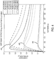
- Processor 312 may map the measured wheel speed measurements to aircraft 100 position data on runway 50 to determine an estimate of the coefficient of friction for portions of runway 50 and/or the slip ratio of the wheel. A skid may occur as the applied brake torque exceeds the available spin up torque created from the tire/runway interface friction. Processor 312 may utilize a measured wheel speed, calculated acceleration, wheel reference and tire normal force estimation mapped to aircraft 100 position data on the runway 50 to determine an estimate of the coefficient of friction and/or the slip ratio as a function of position. In response to landings that involve the anti-skid function, peak wheel accelerations may be used to estimate a peak coefficient of friction (see Figure 4 ). The wheel speed and wheel reference may be used to estimate slip ratio. The peak wheel acceleration and tire normal force may be used to estimate the coefficient of friction.
- the slip ratio value corresponding to the peak coefficient of friction may define the peak slip ratio.
- measured wheel speed, calculated acceleration, wheel reference, and tire normal force estimation may be used to estimate a lower bound of the wheel slip value and/or coefficient of friction.
- a low speed threshold such as wheel speed sensor dropout (about 10 kts, about 18.52 Km/hr)
- an estimate of aircraft 100 weight is obtained and the instantaneous runway 50 friction property may be calculated for each of the braked wheels as a function of aircraft 100 position data (previously recorded, such as by location sensor 330).
- a low speed threshold may involve the aircraft being free from forces which would alter the tire normal forces.
- Estimating the weight of the aircraft may involve determining a tire pressure of a tire of the first braked wheel and calculating the weight of the aircraft based on the determined change tire pressure from a known reference value. This is coupled with the distance between the aircraft touchdown position and low speed threshold condition position.
- the tire pressure sensor helps with the identification of the spring constant to associate with the tire and the distance and assists the identification of the tire radius.
- Aircraft position may be ascertained more than once after wheel speed sensor drop out to verify tire radius. This may assist with the estimation the tire normal force which is used with calculate the friction property data.
- This calculation may be done "after-the-fact" as an accurate aircraft 100 weight measurement cannot generally be obtained during the landing due to transient lift and aircraft pitching due to braking. This may include but is not limited to the aircraft pitching which may occur during antiskid cycling. For instance, at certain speeds, lift from the wings may substantially affect a weight measurement. Thus, this after-the-fact calculation may be made in response to aircraft 100 traveling at a speed where there is no lift adversely affecting the calculation.
- Runway 50 touchdown and/or a low speed threshold location data may be obtained from a position/location sensor 330, such as a GPS unit/receiver.
- the positioning data may be used in conjunction with a measured number of wheel rotations for each wheel.
- the wheel rotation count and the wheel radius may be used to estimate the absolute runway 50 positions; which, in turn, have associated slip and friction values (which may be calculated/extrapolated from the measured wheel speed, calculated acceleration, wheel reference and tire normal force estimation at those locations).
- This information may be transmitted to a system external to aircraft 100 and made available for additional aircraft landing on runway 50.
- the findings of the actual location, e.g. portions of runway 50 traveled by aircraft 100, during a landing event, at various intervals may be aggregated with measured results of other aircraft having brake control system 101 to develop an expanded knowledge of runway 50 and its characteristics for a period of time.
- Brake control system 101 may create a moving average of the data to identify longer-term trends of the coefficient of friction and/or the slip ratio as a function of position.
- This expanded knowledge of runway 50 characteristics may be communicated to additional components of aircraft 100 and/or other aircraft in the vicinity or expected to be in the vicinity so that appropriate action may be taken.
- wheel speed information is collected. Initially, each wheel is subject to a spin up condition, to bring the wheels up from substantially stationary to a rolling speed which is the same as aircraft 100 during landing. During this period, a touchdown protection phase is enacted so that no brakes are applied.
- a wheel reference value measurement is made.
- a wheel reference value may be an estimate of aircraft 100 speed measured at each wheel.
- the reference speed may be updated at any suitable time. For instance the reference speed may be continuously updated throughout the braking event and continues until low speed threshold condition.
- aircraft 100 equivalent speed which is the instantaneous wheel speed and wheel reference data may be initial quantities for brake control system 101.
- these values should be substantially equivalent.
- a drag force is generated.
- these values (e.g. the instantaneous wheel speed and the wheel reference value) separate.
- the brake pressure from sensors 342, 344, 346, 348 and/or the tire pressure from sensors 332, 334, 336, 338 may be measured at this time.
- Based on the friction generated, the rotation of each wheel relative to aircraft 100 speed is decreased.
- An aircraft reference speed is calculated/estimated and is calculated as a weighted combination of the individual wheel reference speeds.
- a graph depicting a coefficient of friction and/or the slip ratio according to various embodiments is presented.
- This data plotted at various times and/or positions may yield information regarding conditions of the runway and capacities of the braking system associated with those conditions. Varied runway conditions will affect the data. For instance, dry runway conditions may be associated with peak 410. Wet runway conditions may be associated with peak 420. Icy runway conditions may be associated with peak 430.
- Brake pressure may be either increasing or decreasing.
- a measured acceleration maximum during a period where aircraft 100 is generating wheel slips corresponds to the peak slip ratio as related in the coefficient of friction vs. slip relationship.
- an estimate of the slip ratio curve and the value of coefficient of friction associated with the slip ratio may be gleaned.
- a peak of a new slip curve may be crossed.
- Each peak, 410, 420, 430 may correspond to a peak acceleration.
- constantly cycling will create multiple estimated peaks for the coefficient of friction vs. slip ratio curve, and the threshold may be crossed multiple times and establish a new peaks at various plotted locations.
- the peak of the new slip curve may be a peak friction point given the slip ratio.
- a lower bound to a slip ratio, and/or a lower bound for the coefficient of friction is established. This lower bound may establish that the wheel is at least capable of this much friction without a slip event. This information may be exploited by aircraft 100.
- brake control unit 310 may be in approach mode and measure feedback data (Step 510). In response to aircraft 100 landing the wheels rotations may be spun up to aircraft 100 speed (Step 520). Aircraft position may be measured (Step 520). Brake control unit 310 may collect additional data in response to the landing. On ground position of the aircraft and/or wheel speed may be measured (Step 530). This may be done at any time and/or at any interval of time. On ground braking active data feedback may be processed for estimation (Step 540). A determination whether the axle pair has reached a wheel speed sensor drop out may be made. (Step 550). If not, return to step 540. (Step 545).
- the low speed threshold (ex. wheel speed sensor drop out speed) sensor may be associated with the aircraft position within the runway system (Step 560).
- the tire pressure measurements and aircraft position data may be used to estimate tire normal force (Step 570).
- Data for creating a map of tire/runway slip ratio and coefficient of friction estimation may be processed (Step 580).
- the tire/runway friction properties may be transmitted and/or stored by the system (Step 590).
- the reference wheel speed and the instantaneous wheel speed will begin to separate as the brakes are applied and friction is produced. These values may be compared by processor 312 utilizing one or more algorithms to determine a slip ratio as a function of aircraft position (Step 560). Acceleration maximums of the wheels may be noted as part of this process 500. A coefficient of friction may be determined/estimated as a function of position. These measured/estimated coefficient of friction values may be mapped to relevant portions of runway 50 (Step 570). Measured values and/or determinations may be stored to memory 314 and/or transmitted by transceiver 316. Note, the systems disclosed herein are applicable to braking during landing and/or during a rejected take-off braking stop.
- coefficient of friction may refer to the ratio of the force that maintains contact between an object and a surface and the frictional force that resists the motion of the object.
- the frictional force may be equal to the coefficient of friction multiplied by the normal force on the surface.
- Slip ratio as used here may refer to a means of calculating and expressing the locking status of a wheel.
- Slip Ratio % [(Vehicle Speed - Wheel Speed)/Vehicle Speed] x 100.
Landscapes
- Engineering & Computer Science (AREA)
- Mechanical Engineering (AREA)
- Transportation (AREA)
- Aviation & Aerospace Engineering (AREA)
- Physics & Mathematics (AREA)
- General Physics & Mathematics (AREA)
- Regulating Braking Force (AREA)
Claims (14)
- Procédé pour déterminer des propriétés de frottement d'interface pneu/piste le long d'une partie d'une piste (50) comprenant :la mesure, par une unité de commande de frein (310), d'une première vitesse de référence d'essieu pour une roue freinée d'un aéronef (100) et d'une accélération de roue ;l'établissement, par l'unité de commande de frein (310), d'une vitesse de référence de roue pour la roue freinée de l'aéronef (100) ;la détermination, par l'unité de commande de frein (310), d'un rapport de glissement de la roue freinée provenant de la première vitesse de référence d'essieu et de la vitesse de référence de roue ;l'évaluation, par l'unité de commande de frein (310), d'un poids de l'aéronef (100) associé à la roue freinée pour fournir une évaluation de la force normale de pneu ;le mappage, par l'unité de commande de frein (310), de données de position à la première vitesse de référence d'essieu, la vitesse de référence de roue, l'accélération de roue et l'évaluation de la force normale de pneu ; etl'évaluation, par l'unité de commande de frein (310), des coefficients de frottement associés aux positions le long de la partie de piste (50) de l'évaluation de la force normale de pneu et de l'accélération de roue ; caractérisé en ce queune limite inférieure des valeurs de glissement de roue est calculée en réponse à un arrêt en freinage ne comprenant pas d'événement de système antidérapage.
- Procédé selon la revendication 1, dans lequel l'établissement de la vitesse de référence de roue de la roue freinée comprend la mesure d'une vitesse de roue d'une roue.
- Procédé selon la revendication 1 ou 2, comprenant en outre la transmission de la vitesse de roue mesurée d'un capteur de vitesse de roue (322, 324, 326, 328) à une unité de commande de frein (310).
- Procédé selon la revendication 1, 2 ou 3, dans lequel l'évaluation du poids de l'aéronef (100) comprend la détermination d'une pression de pneu d'un pneu de la première roue freinée, et le calcul du poids de l'aéronef (100) en fonction de la pression de pneu de rechange déterminée à partir d'une valeur de référence connue.
- Procédé selon l'une quelconque des revendications précédentes, comprenant en outre le calcul de données de position provenant d'un capteur de position (330), par exemple d'une unité de positionnement global.
- Procédé selon l'une quelconque des revendications précédentes, comprenant en outre l'évaluation, par l'unité de commande de frein (310), d'une pointe de rapport de glissement associée aux positions le long de la piste (50).
- Procédé selon l'une quelconque des revendications précédentes, comprenant en outre l'utilisation d'une condition de seuil de faible vitesse pour réduire les perturbations de force normale de pneu.
- Procédé selon l'une quelconque des revendications précédentes, comprenant en outre la transmission du coefficient de frottement déterminé associé à la partie de la piste (50) à une unité centrale.
- Procédé selon l'une quelconque des revendications précédentes, comprenant en outre l'agrégation des informations du coefficient de frottement déterminé provenant d'un aéronef supplémentaire pour établir un mappage étendu du coefficient de frottement associé à la piste (50).
- Procédé selon l'une quelconque des revendications précédentes, dans lequel la partie de la piste (50) est associée à un chemin de circulation de l'aéronef (100).
- Procédé selon l'une quelconque des revendications précédentes, dans lequel un événement de système antidérapage associé à l'aéronef est utilisé pour créer des évaluations des propriétés de frottement de la piste ; et/ou dans lequel des accélérations de roue de pointe sont utilisées pour évaluer les valeurs de rapport de glissement de pointe.
- Procédé selon l'une quelconque des revendications précédentes, dans lequel les coefficients de frottement déterminés associés aux positions le long de la partie de la piste (50) sont exploités pour détecter un début d'un dérapage de roue.
- Procédé selon l'une quelconque des revendications précédentes, dans lequel les coefficients de frottement déterminés associés aux positions le long de la piste (50) sont exploités pour obtenir au moins une des conditions de freinage régulières et efficaces.
- Système comprenant :
une mémoire tangible, non transitoire communiquant avec un processeur, la mémoire tangible, non transitoire ayant des instructions enregistrées sur celle-ci qui, en réponse à une exécution par le processeur, entraîne le processeur à effectuer des opérations conformément au procédé de l'une quelconque des revendications précédentes.
Applications Claiming Priority (2)
| Application Number | Priority Date | Filing Date | Title |
|---|---|---|---|
| US13/935,137 US20150012201A1 (en) | 2013-07-03 | 2013-07-03 | Brake control system comprising runway friction property estimation mapping |
| US13/968,060 US9156451B2 (en) | 2013-07-03 | 2013-08-15 | Brake control system comprising tire/runway friction property estimation mapping |
Publications (2)
| Publication Number | Publication Date |
|---|---|
| EP2821302A1 EP2821302A1 (fr) | 2015-01-07 |
| EP2821302B1 true EP2821302B1 (fr) | 2018-11-28 |
Family
ID=50972460
Family Applications (1)
| Application Number | Title | Priority Date | Filing Date |
|---|---|---|---|
| EP14171610.0A Active EP2821302B1 (fr) | 2013-07-03 | 2014-06-06 | Système de commande de frein comprenant un mappage d'évaluation de la propriété de frottement de pneu/piste |
Country Status (2)
| Country | Link |
|---|---|
| US (1) | US9156451B2 (fr) |
| EP (1) | EP2821302B1 (fr) |
Families Citing this family (10)
| Publication number | Priority date | Publication date | Assignee | Title |
|---|---|---|---|---|
| US10525945B2 (en) * | 2017-04-18 | 2020-01-07 | Goodrich Corporation | Antiskid brake control system with axle-mounted inertial sensor |
| US10147331B1 (en) | 2017-05-15 | 2018-12-04 | Goodrich Corporation | Assessing runway surface conditions |
| JP6976833B2 (ja) * | 2017-12-14 | 2021-12-08 | 株式会社ブリヂストン | 摩耗量予測方法、摩耗量予測装置、及び摩耗量予測プログラム |
| US10730491B2 (en) | 2018-04-20 | 2020-08-04 | Goodrich Corporation | Energy-based antiskid brake control system |
| US11970151B2 (en) * | 2020-03-06 | 2024-04-30 | Goodrich Corporation | Systems and methods for aircraft antiskid braking |
| US11932222B2 (en) | 2020-09-04 | 2024-03-19 | Goodrich Corporation | Systems and methods for low speed braking operation |
| US12025994B2 (en) * | 2020-12-23 | 2024-07-02 | Rockwell Collins, Inc. | Rejected takeoff aircraft system and method |
| USD953371S1 (en) | 2021-10-22 | 2022-05-31 | BioReference Health, LLC | Display screen or portion thereof with animated graphical user interface |
| CN113879518B (zh) * | 2021-11-19 | 2024-06-14 | 中国商用飞机有限责任公司 | 防滑控制方法、装置、电子设备和可读存储介质 |
| GB2617065A (en) * | 2022-03-25 | 2023-10-04 | Airbus Operations Ltd | Monitoring friction associated with a plurality of aircraft wheels |
Family Cites Families (7)
| Publication number | Priority date | Publication date | Assignee | Title |
|---|---|---|---|---|
| US6125318A (en) * | 1998-02-12 | 2000-09-26 | The B. F. Goodrich Company | Slip ratio antiskid controller using mu/slip ratio generated velocity reference |
| US6882920B2 (en) * | 2003-04-29 | 2005-04-19 | Goodrich Corporation | Brake control system |
| NO320851B1 (no) | 2004-04-15 | 2006-02-06 | Oddvard Johnsen | Kontrollerfunksjoner for brems basert pa en styring etter variasjoner i akselerasjonsverdier i hjulets horisontale plan |
| US7797095B2 (en) | 2005-02-23 | 2010-09-14 | Aviation Safety Technologies, Llc | Method and device of calculating aircraft braking friction and other relating landing performance parameters based on the data received from aircraft's on board flight data management system |
| US7945422B2 (en) * | 2009-01-16 | 2011-05-17 | Honeywell International Inc. | Tire pressure augmented aircraft weight and balance system and method |
| US8773289B2 (en) | 2010-03-24 | 2014-07-08 | The Boeing Company | Runway condition monitoring |
| FR2978736B1 (fr) * | 2011-08-01 | 2013-09-27 | Airbus Operations Sas | Dispositif et procede de determination d'un etat de piste, aeronef comprenant un tel dispositif et systeme d'aide au pilotage exploitant cet etat de piste |
-
2013
- 2013-08-15 US US13/968,060 patent/US9156451B2/en active Active
-
2014
- 2014-06-06 EP EP14171610.0A patent/EP2821302B1/fr active Active
Non-Patent Citations (1)
| Title |
|---|
| None * |
Also Published As
| Publication number | Publication date |
|---|---|
| US20150012153A1 (en) | 2015-01-08 |
| US9156451B2 (en) | 2015-10-13 |
| EP2821302A1 (fr) | 2015-01-07 |
Similar Documents
| Publication | Publication Date | Title |
|---|---|---|
| EP2873573B1 (fr) | Consolidation de carte de frottement à l'interface entre le pneu d'aéronef et la piste d'atterrissage | |
| US9156451B2 (en) | Brake control system comprising tire/runway friction property estimation mapping | |
| EP2873574B1 (fr) | Initiation de commande de frein à l'aide des données cartographiques à frottement de roulement de pneu | |
| US20150012201A1 (en) | Brake control system comprising runway friction property estimation mapping | |
| US8965657B2 (en) | System and method for detecting an on ground condition of an aircraft | |
| EP3181416B1 (fr) | Système et procédé de détection de mauvaises conditions de piste | |
| US11027718B2 (en) | Brake wear reduction apparatus | |
| US8942861B2 (en) | Road surface condition estimation method, and road surface condition estimation apparatus | |
| EP2995520B1 (fr) | Procédé d'estimation d'état au sol d'un pneu | |
| EP2005140B1 (fr) | Procede pour collecter des informations concernant la glissance de surface de route | |
| US20170267220A1 (en) | Antilock braking systems, devices, and methods using sensorized brake pads | |
| EP3403892B1 (fr) | Évaluation des conditions de surface d'une piste | |
| CN110382326A (zh) | 高速正常行驶状况下的轮胎路面摩擦系数估算方法和轮胎路面摩擦系数估算装置 | |
| EP3556619B1 (fr) | Système de commande de frein antidérapage fonctionnant à l'énergie | |
| KR101540902B1 (ko) | 노면 마찰계수 추정 장치 및 그 방법 | |
| CN105752325A (zh) | 基于刹车力矩反馈的飞机防滑刹车控制方法 | |
| EP3611064A1 (fr) | Système de commande de freinage antidérapage avec capteur d'inertie monté sur essieu | |
| JP5705051B2 (ja) | 路面状態推定方法、及び路面状態推定装置 | |
| CN201895662U (zh) | 一种电动汽车最佳滑移率识别系统 | |
| KR101910621B1 (ko) | Abs 휠스피드 센서를 이용한 타이어 공기압 추정 장치 및 방법 |
Legal Events
| Date | Code | Title | Description |
|---|---|---|---|
| PUAI | Public reference made under article 153(3) epc to a published international application that has entered the european phase |
Free format text: ORIGINAL CODE: 0009012 |
|
| 17P | Request for examination filed |
Effective date: 20140606 |
|
| AK | Designated contracting states |
Kind code of ref document: A1 Designated state(s): AL AT BE BG CH CY CZ DE DK EE ES FI FR GB GR HR HU IE IS IT LI LT LU LV MC MK MT NL NO PL PT RO RS SE SI SK SM TR |
|
| AX | Request for extension of the european patent |
Extension state: BA ME |
|
| R17P | Request for examination filed (corrected) |
Effective date: 20150629 |
|
| RBV | Designated contracting states (corrected) |
Designated state(s): AL AT BE BG CH CY CZ DE DK EE ES FI FR GB GR HR HU IE IS IT LI LT LU LV MC MK MT NL NO PL PT RO RS SE SI SK SM TR |
|
| GRAP | Despatch of communication of intention to grant a patent |
Free format text: ORIGINAL CODE: EPIDOSNIGR1 |
|
| STAA | Information on the status of an ep patent application or granted ep patent |
Free format text: STATUS: GRANT OF PATENT IS INTENDED |
|
| RIC1 | Information provided on ipc code assigned before grant |
Ipc: G08G 5/00 20060101ALI20180508BHEP Ipc: B60T 8/172 20060101ALI20180508BHEP Ipc: G05D 1/06 20060101ALI20180508BHEP Ipc: B60T 8/17 20060101AFI20180508BHEP |
|
| INTG | Intention to grant announced |
Effective date: 20180607 |
|
| GRAS | Grant fee paid |
Free format text: ORIGINAL CODE: EPIDOSNIGR3 |
|
| GRAA | (expected) grant |
Free format text: ORIGINAL CODE: 0009210 |
|
| STAA | Information on the status of an ep patent application or granted ep patent |
Free format text: STATUS: THE PATENT HAS BEEN GRANTED |
|
| AK | Designated contracting states |
Kind code of ref document: B1 Designated state(s): AL AT BE BG CH CY CZ DE DK EE ES FI FR GB GR HR HU IE IS IT LI LT LU LV MC MK MT NL NO PL PT RO RS SE SI SK SM TR |
|
| REG | Reference to a national code |
Ref country code: CH Ref legal event code: EP |
|
| REG | Reference to a national code |
Ref country code: DE Ref legal event code: R096 Ref document number: 602014036811 Country of ref document: DE |
|
| REG | Reference to a national code |
Ref country code: AT Ref legal event code: REF Ref document number: 1069853 Country of ref document: AT Kind code of ref document: T Effective date: 20181215 |
|
| REG | Reference to a national code |
Ref country code: IE Ref legal event code: FG4D |
|
| REG | Reference to a national code |
Ref country code: NL Ref legal event code: MP Effective date: 20181128 |
|
| REG | Reference to a national code |
Ref country code: LT Ref legal event code: MG4D |
|
| REG | Reference to a national code |
Ref country code: AT Ref legal event code: MK05 Ref document number: 1069853 Country of ref document: AT Kind code of ref document: T Effective date: 20181128 |
|
| PG25 | Lapsed in a contracting state [announced via postgrant information from national office to epo] |
Ref country code: AT Free format text: LAPSE BECAUSE OF FAILURE TO SUBMIT A TRANSLATION OF THE DESCRIPTION OR TO PAY THE FEE WITHIN THE PRESCRIBED TIME-LIMIT Effective date: 20181128 Ref country code: LV Free format text: LAPSE BECAUSE OF FAILURE TO SUBMIT A TRANSLATION OF THE DESCRIPTION OR TO PAY THE FEE WITHIN THE PRESCRIBED TIME-LIMIT Effective date: 20181128 Ref country code: HR Free format text: LAPSE BECAUSE OF FAILURE TO SUBMIT A TRANSLATION OF THE DESCRIPTION OR TO PAY THE FEE WITHIN THE PRESCRIBED TIME-LIMIT Effective date: 20181128 Ref country code: FI Free format text: LAPSE BECAUSE OF FAILURE TO SUBMIT A TRANSLATION OF THE DESCRIPTION OR TO PAY THE FEE WITHIN THE PRESCRIBED TIME-LIMIT Effective date: 20181128 Ref country code: BG Free format text: LAPSE BECAUSE OF FAILURE TO SUBMIT A TRANSLATION OF THE DESCRIPTION OR TO PAY THE FEE WITHIN THE PRESCRIBED TIME-LIMIT Effective date: 20190228 Ref country code: ES Free format text: LAPSE BECAUSE OF FAILURE TO SUBMIT A TRANSLATION OF THE DESCRIPTION OR TO PAY THE FEE WITHIN THE PRESCRIBED TIME-LIMIT Effective date: 20181128 Ref country code: LT Free format text: LAPSE BECAUSE OF FAILURE TO SUBMIT A TRANSLATION OF THE DESCRIPTION OR TO PAY THE FEE WITHIN THE PRESCRIBED TIME-LIMIT Effective date: 20181128 Ref country code: NO Free format text: LAPSE BECAUSE OF FAILURE TO SUBMIT A TRANSLATION OF THE DESCRIPTION OR TO PAY THE FEE WITHIN THE PRESCRIBED TIME-LIMIT Effective date: 20190228 Ref country code: IS Free format text: LAPSE BECAUSE OF FAILURE TO SUBMIT A TRANSLATION OF THE DESCRIPTION OR TO PAY THE FEE WITHIN THE PRESCRIBED TIME-LIMIT Effective date: 20190328 |
|
| PG25 | Lapsed in a contracting state [announced via postgrant information from national office to epo] |
Ref country code: RS Free format text: LAPSE BECAUSE OF FAILURE TO SUBMIT A TRANSLATION OF THE DESCRIPTION OR TO PAY THE FEE WITHIN THE PRESCRIBED TIME-LIMIT Effective date: 20181128 Ref country code: PT Free format text: LAPSE BECAUSE OF FAILURE TO SUBMIT A TRANSLATION OF THE DESCRIPTION OR TO PAY THE FEE WITHIN THE PRESCRIBED TIME-LIMIT Effective date: 20190328 Ref country code: GR Free format text: LAPSE BECAUSE OF FAILURE TO SUBMIT A TRANSLATION OF THE DESCRIPTION OR TO PAY THE FEE WITHIN THE PRESCRIBED TIME-LIMIT Effective date: 20190301 Ref country code: AL Free format text: LAPSE BECAUSE OF FAILURE TO SUBMIT A TRANSLATION OF THE DESCRIPTION OR TO PAY THE FEE WITHIN THE PRESCRIBED TIME-LIMIT Effective date: 20181128 Ref country code: SE Free format text: LAPSE BECAUSE OF FAILURE TO SUBMIT A TRANSLATION OF THE DESCRIPTION OR TO PAY THE FEE WITHIN THE PRESCRIBED TIME-LIMIT Effective date: 20181128 |
|
| PG25 | Lapsed in a contracting state [announced via postgrant information from national office to epo] |
Ref country code: NL Free format text: LAPSE BECAUSE OF FAILURE TO SUBMIT A TRANSLATION OF THE DESCRIPTION OR TO PAY THE FEE WITHIN THE PRESCRIBED TIME-LIMIT Effective date: 20181128 |
|
| PG25 | Lapsed in a contracting state [announced via postgrant information from national office to epo] |
Ref country code: DK Free format text: LAPSE BECAUSE OF FAILURE TO SUBMIT A TRANSLATION OF THE DESCRIPTION OR TO PAY THE FEE WITHIN THE PRESCRIBED TIME-LIMIT Effective date: 20181128 Ref country code: PL Free format text: LAPSE BECAUSE OF FAILURE TO SUBMIT A TRANSLATION OF THE DESCRIPTION OR TO PAY THE FEE WITHIN THE PRESCRIBED TIME-LIMIT Effective date: 20181128 Ref country code: CZ Free format text: LAPSE BECAUSE OF FAILURE TO SUBMIT A TRANSLATION OF THE DESCRIPTION OR TO PAY THE FEE WITHIN THE PRESCRIBED TIME-LIMIT Effective date: 20181128 Ref country code: IT Free format text: LAPSE BECAUSE OF FAILURE TO SUBMIT A TRANSLATION OF THE DESCRIPTION OR TO PAY THE FEE WITHIN THE PRESCRIBED TIME-LIMIT Effective date: 20181128 |
|
| REG | Reference to a national code |
Ref country code: DE Ref legal event code: R097 Ref document number: 602014036811 Country of ref document: DE |
|
| PG25 | Lapsed in a contracting state [announced via postgrant information from national office to epo] |
Ref country code: SK Free format text: LAPSE BECAUSE OF FAILURE TO SUBMIT A TRANSLATION OF THE DESCRIPTION OR TO PAY THE FEE WITHIN THE PRESCRIBED TIME-LIMIT Effective date: 20181128 Ref country code: SM Free format text: LAPSE BECAUSE OF FAILURE TO SUBMIT A TRANSLATION OF THE DESCRIPTION OR TO PAY THE FEE WITHIN THE PRESCRIBED TIME-LIMIT Effective date: 20181128 Ref country code: EE Free format text: LAPSE BECAUSE OF FAILURE TO SUBMIT A TRANSLATION OF THE DESCRIPTION OR TO PAY THE FEE WITHIN THE PRESCRIBED TIME-LIMIT Effective date: 20181128 Ref country code: RO Free format text: LAPSE BECAUSE OF FAILURE TO SUBMIT A TRANSLATION OF THE DESCRIPTION OR TO PAY THE FEE WITHIN THE PRESCRIBED TIME-LIMIT Effective date: 20181128 |
|
| PLBE | No opposition filed within time limit |
Free format text: ORIGINAL CODE: 0009261 |
|
| STAA | Information on the status of an ep patent application or granted ep patent |
Free format text: STATUS: NO OPPOSITION FILED WITHIN TIME LIMIT |
|
| PG25 | Lapsed in a contracting state [announced via postgrant information from national office to epo] |
Ref country code: SI Free format text: LAPSE BECAUSE OF FAILURE TO SUBMIT A TRANSLATION OF THE DESCRIPTION OR TO PAY THE FEE WITHIN THE PRESCRIBED TIME-LIMIT Effective date: 20181128 |
|
| 26N | No opposition filed |
Effective date: 20190829 |
|
| REG | Reference to a national code |
Ref country code: DE Ref legal event code: R119 Ref document number: 602014036811 Country of ref document: DE |
|
| PG25 | Lapsed in a contracting state [announced via postgrant information from national office to epo] |
Ref country code: MC Free format text: LAPSE BECAUSE OF FAILURE TO SUBMIT A TRANSLATION OF THE DESCRIPTION OR TO PAY THE FEE WITHIN THE PRESCRIBED TIME-LIMIT Effective date: 20181128 |
|
| REG | Reference to a national code |
Ref country code: CH Ref legal event code: PL |
|
| REG | Reference to a national code |
Ref country code: BE Ref legal event code: MM Effective date: 20190630 |
|
| PG25 | Lapsed in a contracting state [announced via postgrant information from national office to epo] |
Ref country code: TR Free format text: LAPSE BECAUSE OF FAILURE TO SUBMIT A TRANSLATION OF THE DESCRIPTION OR TO PAY THE FEE WITHIN THE PRESCRIBED TIME-LIMIT Effective date: 20181128 |
|
| PG25 | Lapsed in a contracting state [announced via postgrant information from national office to epo] |
Ref country code: IE Free format text: LAPSE BECAUSE OF NON-PAYMENT OF DUE FEES Effective date: 20190606 Ref country code: DE Free format text: LAPSE BECAUSE OF NON-PAYMENT OF DUE FEES Effective date: 20200101 |
|
| PG25 | Lapsed in a contracting state [announced via postgrant information from national office to epo] |
Ref country code: CH Free format text: LAPSE BECAUSE OF NON-PAYMENT OF DUE FEES Effective date: 20190630 Ref country code: LU Free format text: LAPSE BECAUSE OF NON-PAYMENT OF DUE FEES Effective date: 20190606 Ref country code: LI Free format text: LAPSE BECAUSE OF NON-PAYMENT OF DUE FEES Effective date: 20190630 Ref country code: BE Free format text: LAPSE BECAUSE OF NON-PAYMENT OF DUE FEES Effective date: 20190630 |
|
| PG25 | Lapsed in a contracting state [announced via postgrant information from national office to epo] |
Ref country code: CY Free format text: LAPSE BECAUSE OF FAILURE TO SUBMIT A TRANSLATION OF THE DESCRIPTION OR TO PAY THE FEE WITHIN THE PRESCRIBED TIME-LIMIT Effective date: 20181128 |
|
| PG25 | Lapsed in a contracting state [announced via postgrant information from national office to epo] |
Ref country code: MT Free format text: LAPSE BECAUSE OF FAILURE TO SUBMIT A TRANSLATION OF THE DESCRIPTION OR TO PAY THE FEE WITHIN THE PRESCRIBED TIME-LIMIT Effective date: 20181128 Ref country code: HU Free format text: LAPSE BECAUSE OF FAILURE TO SUBMIT A TRANSLATION OF THE DESCRIPTION OR TO PAY THE FEE WITHIN THE PRESCRIBED TIME-LIMIT; INVALID AB INITIO Effective date: 20140606 |
|
| PG25 | Lapsed in a contracting state [announced via postgrant information from national office to epo] |
Ref country code: MK Free format text: LAPSE BECAUSE OF FAILURE TO SUBMIT A TRANSLATION OF THE DESCRIPTION OR TO PAY THE FEE WITHIN THE PRESCRIBED TIME-LIMIT Effective date: 20181128 |
|
| P01 | Opt-out of the competence of the unified patent court (upc) registered |
Effective date: 20230522 |
|
| PGFP | Annual fee paid to national office [announced via postgrant information from national office to epo] |
Ref country code: GB Payment date: 20250520 Year of fee payment: 12 |
|
| PGFP | Annual fee paid to national office [announced via postgrant information from national office to epo] |
Ref country code: FR Payment date: 20250520 Year of fee payment: 12 |