EP2821579A1 - A device for opening and closing a pivoting wing - Google Patents
A device for opening and closing a pivoting wing Download PDFInfo
- Publication number
- EP2821579A1 EP2821579A1 EP14162198.7A EP14162198A EP2821579A1 EP 2821579 A1 EP2821579 A1 EP 2821579A1 EP 14162198 A EP14162198 A EP 14162198A EP 2821579 A1 EP2821579 A1 EP 2821579A1
- Authority
- EP
- European Patent Office
- Prior art keywords
- wing
- closing
- arm
- slide
- pin
- Prior art date
- Legal status (The legal status is an assumption and is not a legal conclusion. Google has not performed a legal analysis and makes no representation as to the accuracy of the status listed.)
- Withdrawn
Links
- 230000005540 biological transmission Effects 0.000 claims abstract description 9
- 241000238631 Hexapoda Species 0.000 description 3
- 230000015572 biosynthetic process Effects 0.000 description 3
- 230000001154 acute effect Effects 0.000 description 1
- XAGFODPZIPBFFR-UHFFFAOYSA-N aluminium Chemical compound [Al] XAGFODPZIPBFFR-UHFFFAOYSA-N 0.000 description 1
- 229910052782 aluminium Inorganic materials 0.000 description 1
- 239000004411 aluminium Substances 0.000 description 1
- 238000004140 cleaning Methods 0.000 description 1
- 238000010276 construction Methods 0.000 description 1
- 206010016256 fatigue Diseases 0.000 description 1
- 238000012423 maintenance Methods 0.000 description 1
Images




Classifications
-
- E—FIXED CONSTRUCTIONS
- E05—LOCKS; KEYS; WINDOW OR DOOR FITTINGS; SAFES
- E05F—DEVICES FOR MOVING WINGS INTO OPEN OR CLOSED POSITION; CHECKS FOR WINGS; WING FITTINGS NOT OTHERWISE PROVIDED FOR, CONCERNED WITH THE FUNCTIONING OF THE WING
- E05F11/00—Man-operated mechanisms for operating wings, including those which also operate the fastening
- E05F11/02—Man-operated mechanisms for operating wings, including those which also operate the fastening for wings in general, e.g. fanlights
- E05F11/08—Man-operated mechanisms for operating wings, including those which also operate the fastening for wings in general, e.g. fanlights with longitudinally-moving bars guided, e.g. by pivoted links, in or on the frame
- E05F11/12—Mechanisms by which the bar shifts the wing
- E05F11/24—Mechanisms by which the bar shifts the wing shifting the wing by pivotally-connected members (moving) in a plane parallel to the pivot axis of the wing
- E05F11/28—Mechanisms by which the bar shifts the wing shifting the wing by pivotally-connected members (moving) in a plane parallel to the pivot axis of the wing consisting of a lever, e.g. an angle lever, and one or more additional links no material
-
- E—FIXED CONSTRUCTIONS
- E05—LOCKS; KEYS; WINDOW OR DOOR FITTINGS; SAFES
- E05D—HINGES OR SUSPENSION DEVICES FOR DOORS, WINDOWS OR WINGS
- E05D15/00—Suspension arrangements for wings
- E05D15/40—Suspension arrangements for wings supported on arms movable in vertical planes
- E05D15/44—Suspension arrangements for wings supported on arms movable in vertical planes with pivoted arms and vertically-sliding guides
-
- E—FIXED CONSTRUCTIONS
- E05—LOCKS; KEYS; WINDOW OR DOOR FITTINGS; SAFES
- E05F—DEVICES FOR MOVING WINGS INTO OPEN OR CLOSED POSITION; CHECKS FOR WINGS; WING FITTINGS NOT OTHERWISE PROVIDED FOR, CONCERNED WITH THE FUNCTIONING OF THE WING
- E05F11/00—Man-operated mechanisms for operating wings, including those which also operate the fastening
- E05F11/02—Man-operated mechanisms for operating wings, including those which also operate the fastening for wings in general, e.g. fanlights
- E05F11/08—Man-operated mechanisms for operating wings, including those which also operate the fastening for wings in general, e.g. fanlights with longitudinally-moving bars guided, e.g. by pivoted links, in or on the frame
- E05F11/12—Mechanisms by which the bar shifts the wing
- E05F11/24—Mechanisms by which the bar shifts the wing shifting the wing by pivotally-connected members (moving) in a plane parallel to the pivot axis of the wing
- E05F11/26—Mechanisms by which the bar shifts the wing shifting the wing by pivotally-connected members (moving) in a plane parallel to the pivot axis of the wing consisting of a lever, e.g. an angle lever, only no material
-
- E—FIXED CONSTRUCTIONS
- E05—LOCKS; KEYS; WINDOW OR DOOR FITTINGS; SAFES
- E05F—DEVICES FOR MOVING WINGS INTO OPEN OR CLOSED POSITION; CHECKS FOR WINGS; WING FITTINGS NOT OTHERWISE PROVIDED FOR, CONCERNED WITH THE FUNCTIONING OF THE WING
- E05F7/00—Accessories for wings not provided for in other groups of this subclass
- E05F7/08—Means for transmitting movements between vertical and horizontal sliding bars, rods, or cables
-
- E—FIXED CONSTRUCTIONS
- E06—DOORS, WINDOWS, SHUTTERS, OR ROLLER BLINDS IN GENERAL; LADDERS
- E06B—FIXED OR MOVABLE CLOSURES FOR OPENINGS IN BUILDINGS, VEHICLES, FENCES OR LIKE ENCLOSURES IN GENERAL, e.g. DOORS, WINDOWS, BLINDS, GATES
- E06B3/00—Window sashes, door leaves, or like elements for closing wall or like openings; Layout of fixed or moving closures, e.g. windows in wall or like openings; Features of rigidly-mounted outer frames relating to the mounting of wing frames
- E06B3/32—Arrangements of wings characterised by the manner of movement; Arrangements of movable wings in openings; Features of wings or frames relating solely to the manner of movement of the wing
- E06B3/34—Arrangements of wings characterised by the manner of movement; Arrangements of movable wings in openings; Features of wings or frames relating solely to the manner of movement of the wing with only one kind of movement
- E06B3/36—Arrangements of wings characterised by the manner of movement; Arrangements of movable wings in openings; Features of wings or frames relating solely to the manner of movement of the wing with only one kind of movement with a single vertical axis of rotation at one side of the opening, or swinging through the opening
-
- E—FIXED CONSTRUCTIONS
- E05—LOCKS; KEYS; WINDOW OR DOOR FITTINGS; SAFES
- E05D—HINGES OR SUSPENSION DEVICES FOR DOORS, WINDOWS OR WINGS
- E05D15/00—Suspension arrangements for wings
- E05D15/40—Suspension arrangements for wings supported on arms movable in vertical planes
- E05D15/406—Suspension arrangements for wings supported on arms movable in vertical planes with pivoted arms and sliding guides
- E05D15/408—Suspension arrangements for wings supported on arms movable in vertical planes with pivoted arms and sliding guides with sliding guides fixed to the wing
-
- E—FIXED CONSTRUCTIONS
- E05—LOCKS; KEYS; WINDOW OR DOOR FITTINGS; SAFES
- E05F—DEVICES FOR MOVING WINGS INTO OPEN OR CLOSED POSITION; CHECKS FOR WINGS; WING FITTINGS NOT OTHERWISE PROVIDED FOR, CONCERNED WITH THE FUNCTIONING OF THE WING
- E05F11/00—Man-operated mechanisms for operating wings, including those which also operate the fastening
- E05F11/02—Man-operated mechanisms for operating wings, including those which also operate the fastening for wings in general, e.g. fanlights
- E05F11/08—Man-operated mechanisms for operating wings, including those which also operate the fastening for wings in general, e.g. fanlights with longitudinally-moving bars guided, e.g. by pivoted links, in or on the frame
- E05F11/10—Mechanisms by which a handle moves the bar
-
- E—FIXED CONSTRUCTIONS
- E05—LOCKS; KEYS; WINDOW OR DOOR FITTINGS; SAFES
- E05Y—INDEXING SCHEME ASSOCIATED WITH SUBCLASSES E05D AND E05F, RELATING TO CONSTRUCTION ELEMENTS, ELECTRIC CONTROL, POWER SUPPLY, POWER SIGNAL OR TRANSMISSION, USER INTERFACES, MOUNTING OR COUPLING, DETAILS, ACCESSORIES, AUXILIARY OPERATIONS NOT OTHERWISE PROVIDED FOR, APPLICATION THEREOF
- E05Y2201/00—Constructional elements; Accessories therefor
- E05Y2201/60—Suspension or transmission members; Accessories therefor
- E05Y2201/622—Suspension or transmission members elements
- E05Y2201/638—Cams; Ramps
-
- E—FIXED CONSTRUCTIONS
- E05—LOCKS; KEYS; WINDOW OR DOOR FITTINGS; SAFES
- E05Y—INDEXING SCHEME ASSOCIATED WITH SUBCLASSES E05D AND E05F, RELATING TO CONSTRUCTION ELEMENTS, ELECTRIC CONTROL, POWER SUPPLY, POWER SIGNAL OR TRANSMISSION, USER INTERFACES, MOUNTING OR COUPLING, DETAILS, ACCESSORIES, AUXILIARY OPERATIONS NOT OTHERWISE PROVIDED FOR, APPLICATION THEREOF
- E05Y2900/00—Application of doors, windows, wings or fittings thereof
- E05Y2900/10—Application of doors, windows, wings or fittings thereof for buildings or parts thereof
- E05Y2900/13—Type of wing
- E05Y2900/148—Windows
Definitions
- the present invention relates to accessories for doors and windows and refers to a device for opening and closing a wing, in particular an outwardly-opening pivoting wing.
- the device according to the invention can be applied to wings articulated about vertical axes or to wings rotatable about horizontal axes.
- Outwardly-opening pivoting wings are sometimes associated with insect screens.
- the device that controls the opening and closing of the wing must be arranged so as not to interfere with the insect screen, to allow the opening and closing of the wing without prior lifting or removal of the insect screen.
- devices are used for opening and closing the wing that are mounted on the frame.
- CH410666 describes a device for opening and closing a pivoting wing, comprising a stationary support attached to the frame, a slide movable relative to the stationary support in a rectilinear direction between an open wing position and a closed wing position, an arm articulated to the stationary support about an articulation axis and having a distal end that slides in a groove of the wing, wherein the slide has a control pin, which engages a cam formed in the arm.
- a drawback of this known solution is that, during closing of the wing, it is necessary to apply a very high torque to the arm when the door is near to the frame to compress the seals, which are usually arranged between the wing and the frame. This causes a high stress of the control pin and the pivot pin, which are therefore subject to a high risk of fatigue failure.
- the present invention aims to provide a device for opening and closing an outwardly-opening pivoting wing that can overcome the drawbacks of the known solutions.
- this object is achieved by a device having the characteristics forming the subject of Claim 1.
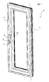
- numeral 10 indicates a window assembly comprising a fixed frame 12 and an outwardly-opening pivoting wing 14.
- the wing 14 is articulated to the frame 12 about an axis A.
- the articulation axis A of the wing 14 is vertical.
- the present invention is also applicable to wings articulated about horizontal axes.
- the frame 12 and the wing 14 are formed from extruded aluminium profiles equipped, in a conventional manner, with longitudinal slots.
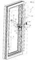
- numeral 16 indicates, as a whole, a device for opening and closing the wing 14.
- the device 16 comprises a control assembly 18, intended for being mounted on the frame 12, and a locking assembly 20 intended for being mounted on the wing 14.
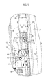
- the control assembly 18 comprises a stationary support 22 including a fixed guide 24 and a fixed cover 26.
- the guide 24 and the cover 26 are intended for being attached to the frame 12 by means of respective screws 28, 30.
- the control assembly 18 comprises a slide 32 movable along a rectilinear direction B parallel to the articulation axis A of the wing 14.
- the slide 32 is guided along the rectilinear direction B of the guide 24.
- the slide 32 In the assembled condition, the slide 32 is located between the cover 26 and the guide 24 and can only move in the rectilinear direction B.
- the slide 32 is movable in the direction B between a closed and locked wing position, a closed and unlocked wing position, and an open wing position.
- the slide 32 comprises a drive pin 34 that controls the locking assembly 20 in the manner that will be described below.
- the slide 32 has a transverse projection 36, which is coupled to an actuating device mounted on the frame 12.
- numeral 38 indicates an actuating device configured to drive the control assembly 18.
- the actuating device 38 comprises a base 40 fixed to the frame 12 and a lever 42 articulated to the base 40, and movable between a lowered position ( Figure 1 ) corresponding to the closed and locked wing position, and a raised position ( Figure 2 ) corresponding to the open wing position.
- the lever 42 controls, via rods 44, a rectilinear movement of an actuating member attached to the transverse projection 36 of the slide 32.
- the movement of the lever 42 from the lowered position to the raised position, and vice versa controls the movement of the slide 32 along the rectilinear direction B between the closed and locked wing position and the open wing position, and vice versa.
- any other actuating device can be used that is configured to control the movement of the slide 32 in the rectilinear direction.
- the control assembly 18 comprises a pivoting arm 52 articulated to the stationary support 22 about an axis C, orthogonal to the rectilinear direction B.
- the arm 52 is articulated to the cover 26 by means of a pivot pin 54 which engages a hole 56 of the arm 52.
- the arm 52 is formed by two sections 58, 60 articulated to each other by means of a hinge 61 about an axis D transverse with respect to the longitudinal direction of the arm 52.
- a first section 58 of the arm 52 is articulated to the cover 26, and a second section 60 of the arm 52 carries a runner 62 articulated to the arm 52 about an axis E parallel to the articulation axis C of the arm 52.
- the runner 62 is intended to engage, in a sliding manner, a groove of the wing 14, parallel to the rectilinear direction B.
- the control assembly 18 comprises a transmission mechanism 43 associated with the slide 32 and the arm 52, configured to transform the rectilinear movement of the slide 32 along the direction B into a pivoting movement of the arm 52 about axis C.
- the transmission mechanism 43 comprises an essentially L-shaped cam 46, engaged by a control pin 64.
- the cam 46 is formed in the slide 32 and the control pin 64 is attached to the first section 58 of the arm 18, but this arrangement could be reversed, i.e. the cam 46 could be formed on the arm 52 and the control pin 64 could be attached to the slide 32.
- the cam 46 is constituted by a groove formed in the slide 32.
- the cam 46 has a first portion 48 parallel to the rectilinear direction B, and a second portion 50 orthogonal to the rectilinear direction B.
- the control pin 64 is parallel and spaced with respect to the pivot axis C of the arm 52, and is free to move along the cam 46
- the control assembly 18 comprises an auxiliary closing mechanism 73 associated with the slide 32 and the arm 52.
- the auxiliary closing mechanism 73 comprises a closing pin 74 cooperating with an inclined plane 76.
- the closing pin 74 is attached to the first arm section 58 and the inclined plane 76 is integrally formed with the slide 32.
- this arrangement could be reversed, i.e. the closing pin 74 could be attached to the slide 32 and the inclined plane 76 could be formed on the arm 52.
- the closing pin 74 is arranged on the opposite side of the articulation axis C with respect to the control pin 64.
- the inclined plane 76 has a ramp surface 82 and a straight surface 84 parallel to the rectilinear direction B.
- the ramp surface 82 is inclined with respect to the rectilinear direction B and ends with an acute angle adjacent to the outer side of the frame 12.
- the auxiliary closing mechanism 73 is configured to apply an additional closing torque to the arm 52 when, during closing, the wing 14 is still open but very near to the frame 12.
- the additional closing torque provided by the auxiliary closing mechanism 73 provides the force required to compress the seals arranged between the wing 14 and the frame 12, without excessively stressing the control pin 64 and the pivot pin 54.
- the locking assembly 20 comprises a driver 66, which is intended to be mounted, in a sliding manner, in a longitudinal groove of the wing 14.
- the driver 66 has an engagement formation 68 that is engaged by the drive pin 34 of the slide 32 in the closed wing position.
- the locking assembly 20 comprises a plurality of transmission rods 70 connected directly or indirectly to the driver 66.
- a plurality of closing elements 72 are attached to the rods 70, which are intended to engage corresponding strikers 78 intended for being attached to the frame 12.
- the closing elements 72 are arranged both along the vertical side and along the upper and lower horizontal sides of the wing 14. To transmit the movement from the driver 66 to the closing elements 72 arranged along the horizontal sides, two angular transmissions 80 are provided.
- the movement in the vertical direction of the drive pin 34 of the slide 32 moves the driver 66 in a vertical direction.
- the movement of the driver 66 simultaneously moves all the closing elements 72 between a locking position and an unlocking position, and vice versa.
- the upward movement of the driver 66 controls the disengagement of the closing elements 72 from the respective fixed strikers 78, while the downward movement of the driver 66 controls the engagement of the closing elements 72 with the respective fixed strikers 78.
- FIGS. 4 , 5 and 6 show the operation of the control assembly 18.
- the slide 32 In the position illustrated in Figure 4 , the slide 32 is in a fully lowered position, corresponding to the closed and locked wing position.
- the control pin 64 of the arm 52 engages the upper end of the first portion 48 of the cam 46.
- the arm 52 is oriented parallel to the guide 24.
- the drive pin 34 engages the engagement formation 68 of the driver 66.
- the driver 66 is in the lowered position and the closing elements 72 engage with the respective strikers 78.
- the closing pin 74 rests against the straight surface 84 of the inclined plane 76.
- the wing 14 is therefore in a closed and locked position.
- a first step of the upward movement of the slide 32 the control pin 64 of the arm 52 travels along the first portion 48 of the cam 46 from the top downwards.
- Figure 5 illustrates the position of the control assembly 18 at the end of this first step of the upward movement of the slide 32.
- the control pin 64 of the arm 52 is at the bottom of the first portion 48 of the cam 46.
- the arm 52 remains immobile. Indeed, in this first step, the control pin 64 engages the first portion 48 of the cam 46, that is parallel to the direction of movement of the slide 32. Therefore, the vertical movement of the slide 32 in this first step does not apply any force to the control pin 64.
- the drive pin 34 of the slide 32 moves the driver 66 of the locking assembly 20 upward.
- the upward movement of the driver 66 disengages the closing elements 72 from the respective strikers 78, and therefore unlocks the wing 14 from the frame 12.
- the closing pin 74 moves downward along the straight surface 84 of the inclined plane 76 and engages with the ramp surface 82 when the control pin 64 is at the bottom of the first portion 48 of the cam 46. In the position of Figure 5 , the wing 14 is in the closed and unlocked position.
- the slide 32 continues to move upward.
- the control pin 64 of the arm 52 engages the second portion 50 of the cam 46, as illustrated in Figure 6 .
- the second portion 50 of the cam 46 applies a force to the control pin 64, which rotates the arm 52 about the axis C. Therefore, in this second part of the upward movement of the slide 32, the arm 52 pivots about the axis C in the direction indicated by the arrow F in Figure 6 .
- the closing pin 74 slides along the ramp surface 82 and disengages from the inclined plane 76.
- the closing maneuver of the wing 14 takes place in an inverse manner to that described previously.
- the lever 42 of the actuating device 38 is rotated from top to bottom, or from bottom to top with a different actuating device.
- the slide 32 moves from the top downwards.
- the control pin 64 engages the second portion 50 of the cam 46.
- the arm 52 rotates in the direction indicated by the arrow G in Figure 7 , from the outwardly-inclined position, corresponding to the open wing position, towards the vertical position corresponding to the closed wing position.
- the device according to the present invention does not necessarily have to be associated with a locking assembly 20 as previously described.
- the control assembly 18 could lock the wing at just one closing point by means of a lug 83 of the slide 32 ( Figure 3 ) that, striker on the wing 14.
- the two sections 58, 60 of the arm 52 are disengagable from each other to allow opening of the wing 14 more than the opening angle allowed by the arm 52.
- section 60 of the arm 52 is releasably attached to the hinge 61.
- section 60 of the arm 52 has a head 85 provided with a notch 86, which is engaged by a grub screw 88 that engages a threaded hole of the hinge 61. Unscrewing the grub screw 88, it is possible to disengage the section 60 from the hinge 61 and to open the wing fully for carrying out cleaning and maintenance.
Landscapes
- Engineering & Computer Science (AREA)
- Mechanical Engineering (AREA)
- Civil Engineering (AREA)
- Structural Engineering (AREA)
- Closing And Opening Devices For Wings, And Checks For Wings (AREA)
- Power-Operated Mechanisms For Wings (AREA)
Applications Claiming Priority (1)
| Application Number | Priority Date | Filing Date | Title |
|---|---|---|---|
| IT000563A ITTO20130563A1 (it) | 2013-07-05 | 2013-07-05 | Dispositivo per l'apertura e la chiusura di un'anta oscillante apribile verso l'esterno |
Publications (1)
| Publication Number | Publication Date |
|---|---|
| EP2821579A1 true EP2821579A1 (en) | 2015-01-07 |
Family
ID=49118710
Family Applications (1)
| Application Number | Title | Priority Date | Filing Date |
|---|---|---|---|
| EP14162198.7A Withdrawn EP2821579A1 (en) | 2013-07-05 | 2014-03-28 | A device for opening and closing a pivoting wing |
Country Status (4)
| Country | Link |
|---|---|
| US (1) | US9512658B2 (it) |
| EP (1) | EP2821579A1 (it) |
| AU (1) | AU2014202634B2 (it) |
| IT (1) | ITTO20130563A1 (it) |
Families Citing this family (17)
| Publication number | Priority date | Publication date | Assignee | Title |
|---|---|---|---|---|
| ITFI20130084A1 (it) * | 2013-04-16 | 2014-10-17 | Fapim S P A | Infisso ad anta puramente girevole |
| US9797176B2 (en) * | 2014-03-20 | 2017-10-24 | Savio S.P.A. | Device for opening and closing an outwardly opening pivoting wing |
| WO2016045113A1 (zh) * | 2014-09-28 | 2016-03-31 | 李增榜 | 一种平开悬挂窗 |
| US20160130847A1 (en) * | 2014-11-12 | 2016-05-12 | Truth Hardware Corporation | Around-the-corner multi-point window lock mechanism for casement and awning windows |
| US9772010B2 (en) * | 2015-06-19 | 2017-09-26 | Milgard Manufacturing Incorporation | Building closure operator |
| ITUB20152156A1 (it) * | 2015-07-14 | 2017-01-14 | Savio Spa | Dispositivo per l'apertura e la chiusura di un'anta oscillante apribile verso l'esterno |
| JP2017025655A (ja) * | 2015-07-27 | 2017-02-02 | アルメタックス株式会社 | 窓の開閉装置 |
| BE1023748B1 (nl) * | 2016-01-07 | 2017-07-11 | PARYS Emmanuel Diederich Camille VAN | Verdektliggend scharnier voor een draai-kip en kip-draai raam en raam daarmee uitgerust |
| US10597916B2 (en) * | 2016-07-06 | 2020-03-24 | Wilh. Schlechtendahl & Söhne Gmbh & Co. Kg (Wss) | Corner deflection means of a fitting for a window casement or a door leaf |
| US11053716B2 (en) * | 2016-08-31 | 2021-07-06 | Interlock Usa, Inc. | Casement window lock bar |
| US12480343B2 (en) * | 2016-10-28 | 2025-11-25 | Assa Abloy Fenestration, Llc | Casement window lock bar |
| US10876343B2 (en) | 2016-12-08 | 2020-12-29 | Pella Corporation | Casement sliding operator |
| CN117924493A (zh) * | 2017-08-09 | 2024-04-26 | 奥里尼斯生物科学有限公司 | Clec9a结合剂及其用途 |
| CA3060764C (en) | 2018-10-31 | 2022-08-23 | Pella Corporation | Slide operator for fenestration unit |
| CA3081316C (en) | 2019-05-24 | 2022-09-06 | Pella Corporation | Slide operator assemblies and components for fenestration units |
| JP7672325B2 (ja) * | 2021-10-25 | 2025-05-07 | 株式会社Lixil | 建具 |
| CA3188624A1 (en) * | 2023-02-03 | 2025-01-17 | Long Ten Technology Inc. | Window and door mechanism |
Citations (4)
| Publication number | Priority date | Publication date | Assignee | Title |
|---|---|---|---|---|
| CH410666A (de) | 1963-04-09 | 1966-03-31 | Mettler Heinrich | Schliesseinrichtung an horizontalachsigem Fensterflügel |
| DE2106569A1 (de) * | 1971-02-11 | 1972-08-24 | Suhr, Heinz-Peter, 3051 Hagenburg | Oberlichtöffner |
| EP0416149A1 (de) * | 1989-09-07 | 1991-03-13 | W. Hautau Gmbh | Flachform-Oberlichtöffner |
| US20060048450A1 (en) * | 2004-09-03 | 2006-03-09 | Curtis Daniel J | Window reive mechanism |
Family Cites Families (6)
| Publication number | Priority date | Publication date | Assignee | Title |
|---|---|---|---|---|
| US2709582A (en) * | 1954-01-14 | 1955-05-31 | Morgan Company | Window |
| DE1087043B (de) * | 1956-08-11 | 1960-08-11 | Wilhelm Suhr | Gruppen-Oberlichtoeffner |
| DE2705965A1 (de) * | 1977-02-14 | 1978-08-17 | Fuhr C Fa | Ausstellbeschlag fuer oberlichtkippfluegel |
| ATE141991T1 (de) * | 1991-09-13 | 1996-09-15 | Hautau Gmbh W | Beschlag für insb. zwangsweise kipp- und parallel abstellbare flügel |
| US20050066579A1 (en) * | 2003-09-25 | 2005-03-31 | Kurt Winner | Linear window operator |
| ITBO20110474A1 (it) * | 2011-07-29 | 2013-01-30 | Gsg Int Spa | Finestra a sporgere. |
-
2013
- 2013-07-05 IT IT000563A patent/ITTO20130563A1/it unknown
-
2014
- 2014-03-28 EP EP14162198.7A patent/EP2821579A1/en not_active Withdrawn
- 2014-05-14 AU AU2014202634A patent/AU2014202634B2/en not_active Expired - Fee Related
- 2014-05-16 US US14/279,518 patent/US9512658B2/en active Active
Patent Citations (4)
| Publication number | Priority date | Publication date | Assignee | Title |
|---|---|---|---|---|
| CH410666A (de) | 1963-04-09 | 1966-03-31 | Mettler Heinrich | Schliesseinrichtung an horizontalachsigem Fensterflügel |
| DE2106569A1 (de) * | 1971-02-11 | 1972-08-24 | Suhr, Heinz-Peter, 3051 Hagenburg | Oberlichtöffner |
| EP0416149A1 (de) * | 1989-09-07 | 1991-03-13 | W. Hautau Gmbh | Flachform-Oberlichtöffner |
| US20060048450A1 (en) * | 2004-09-03 | 2006-03-09 | Curtis Daniel J | Window reive mechanism |
Also Published As
| Publication number | Publication date |
|---|---|
| ITTO20130563A1 (it) | 2015-01-06 |
| US20150013230A1 (en) | 2015-01-15 |
| US9512658B2 (en) | 2016-12-06 |
| AU2014202634B2 (en) | 2018-05-31 |
| AU2014202634A1 (en) | 2015-01-22 |
Similar Documents
| Publication | Publication Date | Title |
|---|---|---|
| US9512658B2 (en) | Device for opening and closing a pivoting wing | |
| US11480001B2 (en) | Casement sliding operator | |
| CA2824909C (en) | Flush lock for casement window | |
| US6161881A (en) | Casement lock | |
| US9797176B2 (en) | Device for opening and closing an outwardly opening pivoting wing | |
| IL289814B (en) | Bolt arrangement with stop bolt | |
| EP2735677B1 (en) | Door/window comprising an operating system with multiple locking points | |
| RU2662696C2 (ru) | Фурнитура для, как минимум, подъёмной, а предпочтительно также и передвижной створки окна или двери | |
| US9790726B2 (en) | Device for opening and closing an outwardly opening pivoting wing | |
| CN100472024C (zh) | 用于带有旋转翼扇的金属门窗框架防误操作的拐角传动装置 | |
| EP2019180B1 (en) | An operating device for windows | |
| CA2580635C (en) | Floor lock | |
| RU2649819C2 (ru) | Фурнитура для подъемной и/или передвижной створки окна или двери | |
| CN107339043A (zh) | 车窗玻璃升降器 | |
| RU2016103593A (ru) | Фурнитура для окна, двери или т.п. с откидно-сдвижной створкой | |
| EP3428376A1 (de) | Beschlag für einen kipp- und schiebbaren flügel und verfahren zum öffnen und schliessen eines parallel abstellbaren und verschiebbaren flügels | |
| EP4108861B1 (en) | Motion multiplication device for windows or doors | |
| EP2103766A2 (de) | Antriebseinrichtung für einen Flügel eines Fensters oder einer Tür | |
| US20190003230A1 (en) | Device for opening and closing an outwardly opening pivoting wing | |
| US20230203866A1 (en) | Seal of Vertically Movable Facade Components | |
| CN115874892A (zh) | 塞拉门总成及车辆 | |
| KR20130055838A (ko) | 양개여닫이 특수도어의 핸들잠금장치 | |
| US20170022745A1 (en) | Control assembly for an outwardly opening pivoting wing | |
| EP2022913A2 (en) | An incorrect operation safety lock device for window units | |
| CA2987612A1 (en) | Sliding operator handle brake |
Legal Events
| Date | Code | Title | Description |
|---|---|---|---|
| PUAI | Public reference made under article 153(3) epc to a published international application that has entered the european phase |
Free format text: ORIGINAL CODE: 0009012 |
|
| 17P | Request for examination filed |
Effective date: 20140328 |
|
| AK | Designated contracting states |
Kind code of ref document: A1 Designated state(s): AL AT BE BG CH CY CZ DE DK EE ES FI FR GB GR HR HU IE IS IT LI LT LU LV MC MK MT NL NO PL PT RO RS SE SI SK SM TR |
|
| AX | Request for extension of the european patent |
Extension state: BA ME |
|
| R17P | Request for examination filed (corrected) |
Effective date: 20150506 |
|
| RBV | Designated contracting states (corrected) |
Designated state(s): AL AT BE BG CH CY CZ DE DK EE ES FI FR GB GR HR HU IE IS IT LI LT LU LV MC MK MT NL NO PL PT RO RS SE SI SK SM TR |
|
| STAA | Information on the status of an ep patent application or granted ep patent |
Free format text: STATUS: THE APPLICATION HAS BEEN WITHDRAWN |
|
| 18W | Application withdrawn |
Effective date: 20180220 |