EP2821680A1 - Zapfenkugelventil für hochdruck und wasserstoffstation - Google Patents
Zapfenkugelventil für hochdruck und wasserstoffstation Download PDFInfo
- Publication number
- EP2821680A1 EP2821680A1 EP13754623.0A EP13754623A EP2821680A1 EP 2821680 A1 EP2821680 A1 EP 2821680A1 EP 13754623 A EP13754623 A EP 13754623A EP 2821680 A1 EP2821680 A1 EP 2821680A1
- Authority
- EP
- European Patent Office
- Prior art keywords
- ball
- sealing
- high pressure
- ball valve
- trunnion
- Prior art date
- Legal status (The legal status is an assumption and is not a legal conclusion. Google has not performed a legal analysis and makes no representation as to the accuracy of the status listed.)
- Granted
Links
Images


Classifications
-
- F—MECHANICAL ENGINEERING; LIGHTING; HEATING; WEAPONS; BLASTING
- F16—ENGINEERING ELEMENTS AND UNITS; GENERAL MEASURES FOR PRODUCING AND MAINTAINING EFFECTIVE FUNCTIONING OF MACHINES OR INSTALLATIONS; THERMAL INSULATION IN GENERAL
- F16K—VALVES; TAPS; COCKS; ACTUATING-FLOATS; DEVICES FOR VENTING OR AERATING
- F16K5/00—Plug valves; Taps or cocks comprising only cut-off apparatus having at least one of the sealing faces shaped as a more or less complete surface of a solid of revolution, the opening and closing movement being predominantly rotary
- F16K5/06—Plug valves; Taps or cocks comprising only cut-off apparatus having at least one of the sealing faces shaped as a more or less complete surface of a solid of revolution, the opening and closing movement being predominantly rotary with plugs having spherical surfaces; Packings therefor
- F16K5/0663—Packings
-
- F—MECHANICAL ENGINEERING; LIGHTING; HEATING; WEAPONS; BLASTING
- F16—ENGINEERING ELEMENTS AND UNITS; GENERAL MEASURES FOR PRODUCING AND MAINTAINING EFFECTIVE FUNCTIONING OF MACHINES OR INSTALLATIONS; THERMAL INSULATION IN GENERAL
- F16K—VALVES; TAPS; COCKS; ACTUATING-FLOATS; DEVICES FOR VENTING OR AERATING
- F16K25/00—Details relating to contact between valve members and seats
- F16K25/005—Particular materials for seats or closure elements
-
- F—MECHANICAL ENGINEERING; LIGHTING; HEATING; WEAPONS; BLASTING
- F16—ENGINEERING ELEMENTS AND UNITS; GENERAL MEASURES FOR PRODUCING AND MAINTAINING EFFECTIVE FUNCTIONING OF MACHINES OR INSTALLATIONS; THERMAL INSULATION IN GENERAL
- F16K—VALVES; TAPS; COCKS; ACTUATING-FLOATS; DEVICES FOR VENTING OR AERATING
- F16K27/00—Construction of housing; Use of materials therefor
- F16K27/06—Construction of housing; Use of materials therefor of taps or cocks
- F16K27/067—Construction of housing; Use of materials therefor of taps or cocks with spherical plugs
-
- F—MECHANICAL ENGINEERING; LIGHTING; HEATING; WEAPONS; BLASTING
- F16—ENGINEERING ELEMENTS AND UNITS; GENERAL MEASURES FOR PRODUCING AND MAINTAINING EFFECTIVE FUNCTIONING OF MACHINES OR INSTALLATIONS; THERMAL INSULATION IN GENERAL
- F16K—VALVES; TAPS; COCKS; ACTUATING-FLOATS; DEVICES FOR VENTING OR AERATING
- F16K31/00—Actuating devices; Operating means; Releasing devices
- F16K31/44—Mechanical actuating means
- F16K31/60—Handles
-
- F—MECHANICAL ENGINEERING; LIGHTING; HEATING; WEAPONS; BLASTING
- F16—ENGINEERING ELEMENTS AND UNITS; GENERAL MEASURES FOR PRODUCING AND MAINTAINING EFFECTIVE FUNCTIONING OF MACHINES OR INSTALLATIONS; THERMAL INSULATION IN GENERAL
- F16K—VALVES; TAPS; COCKS; ACTUATING-FLOATS; DEVICES FOR VENTING OR AERATING
- F16K5/00—Plug valves; Taps or cocks comprising only cut-off apparatus having at least one of the sealing faces shaped as a more or less complete surface of a solid of revolution, the opening and closing movement being predominantly rotary
- F16K5/06—Plug valves; Taps or cocks comprising only cut-off apparatus having at least one of the sealing faces shaped as a more or less complete surface of a solid of revolution, the opening and closing movement being predominantly rotary with plugs having spherical surfaces; Packings therefor
- F16K5/0626—Easy mounting or dismounting means
- F16K5/0636—Easy mounting or dismounting means the spherical plug being insertable from the top of the housing
-
- F—MECHANICAL ENGINEERING; LIGHTING; HEATING; WEAPONS; BLASTING
- F16—ENGINEERING ELEMENTS AND UNITS; GENERAL MEASURES FOR PRODUCING AND MAINTAINING EFFECTIVE FUNCTIONING OF MACHINES OR INSTALLATIONS; THERMAL INSULATION IN GENERAL
- F16K—VALVES; TAPS; COCKS; ACTUATING-FLOATS; DEVICES FOR VENTING OR AERATING
- F16K5/00—Plug valves; Taps or cocks comprising only cut-off apparatus having at least one of the sealing faces shaped as a more or less complete surface of a solid of revolution, the opening and closing movement being predominantly rotary
- F16K5/06—Plug valves; Taps or cocks comprising only cut-off apparatus having at least one of the sealing faces shaped as a more or less complete surface of a solid of revolution, the opening and closing movement being predominantly rotary with plugs having spherical surfaces; Packings therefor
- F16K5/0647—Spindles or actuating means
-
- F—MECHANICAL ENGINEERING; LIGHTING; HEATING; WEAPONS; BLASTING
- F16—ENGINEERING ELEMENTS AND UNITS; GENERAL MEASURES FOR PRODUCING AND MAINTAINING EFFECTIVE FUNCTIONING OF MACHINES OR INSTALLATIONS; THERMAL INSULATION IN GENERAL
- F16K—VALVES; TAPS; COCKS; ACTUATING-FLOATS; DEVICES FOR VENTING OR AERATING
- F16K5/00—Plug valves; Taps or cocks comprising only cut-off apparatus having at least one of the sealing faces shaped as a more or less complete surface of a solid of revolution, the opening and closing movement being predominantly rotary
- F16K5/06—Plug valves; Taps or cocks comprising only cut-off apparatus having at least one of the sealing faces shaped as a more or less complete surface of a solid of revolution, the opening and closing movement being predominantly rotary with plugs having spherical surfaces; Packings therefor
- F16K5/0657—Particular coverings or materials
-
- F—MECHANICAL ENGINEERING; LIGHTING; HEATING; WEAPONS; BLASTING
- F16—ENGINEERING ELEMENTS AND UNITS; GENERAL MEASURES FOR PRODUCING AND MAINTAINING EFFECTIVE FUNCTIONING OF MACHINES OR INSTALLATIONS; THERMAL INSULATION IN GENERAL
- F16K—VALVES; TAPS; COCKS; ACTUATING-FLOATS; DEVICES FOR VENTING OR AERATING
- F16K5/00—Plug valves; Taps or cocks comprising only cut-off apparatus having at least one of the sealing faces shaped as a more or less complete surface of a solid of revolution, the opening and closing movement being predominantly rotary
- F16K5/06—Plug valves; Taps or cocks comprising only cut-off apparatus having at least one of the sealing faces shaped as a more or less complete surface of a solid of revolution, the opening and closing movement being predominantly rotary with plugs having spherical surfaces; Packings therefor
- F16K5/0663—Packings
- F16K5/0668—Single packings
-
- F—MECHANICAL ENGINEERING; LIGHTING; HEATING; WEAPONS; BLASTING
- F16—ENGINEERING ELEMENTS AND UNITS; GENERAL MEASURES FOR PRODUCING AND MAINTAINING EFFECTIVE FUNCTIONING OF MACHINES OR INSTALLATIONS; THERMAL INSULATION IN GENERAL
- F16K—VALVES; TAPS; COCKS; ACTUATING-FLOATS; DEVICES FOR VENTING OR AERATING
- F16K5/00—Plug valves; Taps or cocks comprising only cut-off apparatus having at least one of the sealing faces shaped as a more or less complete surface of a solid of revolution, the opening and closing movement being predominantly rotary
- F16K5/08—Details
- F16K5/14—Special arrangements for separating the sealing faces or for pressing them together
- F16K5/20—Special arrangements for separating the sealing faces or for pressing them together for plugs with spherical surfaces
- F16K5/201—Special arrangements for separating the sealing faces or for pressing them together for plugs with spherical surfaces with the housing or parts of the housing mechanically pressing the seal against the plug
-
- F—MECHANICAL ENGINEERING; LIGHTING; HEATING; WEAPONS; BLASTING
- F16—ENGINEERING ELEMENTS AND UNITS; GENERAL MEASURES FOR PRODUCING AND MAINTAINING EFFECTIVE FUNCTIONING OF MACHINES OR INSTALLATIONS; THERMAL INSULATION IN GENERAL
- F16K—VALVES; TAPS; COCKS; ACTUATING-FLOATS; DEVICES FOR VENTING OR AERATING
- F16K5/00—Plug valves; Taps or cocks comprising only cut-off apparatus having at least one of the sealing faces shaped as a more or less complete surface of a solid of revolution, the opening and closing movement being predominantly rotary
- F16K5/08—Details
- F16K5/22—Features relating to lubrication
- F16K5/227—Features relating to lubrication for plugs with spherical surfaces
Definitions
- the present invention relates to a ball valve, in particular, a trunnion ball valve for high pressure suitable for use in a facility such as a hydrogen station in which high-pressure fluid such as hydrogen flows, and further relates to a hydrogen station.
- a valve for high-pressure fluid As a valve for flowing such a high-pressure fluid, for example a needle valve disclosed in Patent Document 1 is known.
- the needle valve has a structure in which a flow channel opens and closes by reciprocation movement of a needle.
- a trunnion ball valve may be used as a valve suitable for a case in which a flow channel is switched on or off while maintaining its flow.
- a known ball valve of this type is, for example, a trunnion ball valve of Patent Document 2.
- This trunnion ball valve is structured so that a ball made of metal is provided inside a body in a rotatable manner via a stem and a trunnion (lower stem), and a seat retainer is provided in which a ball seat for sealing is provided on both sides of the ball.
- a valve for high pressure requires maintaining high sealing performance to securely prevent leakage. Furthermore, in order to secure operability of the valve under high pressure, it is also necessary to satisfy sliding ability between the stem and the seat.
- a trunnion ball valve for high pressure gas for improving sealing performance between the ball and the seat is a ball valve disclosed in Patent Document 3.
- this ball valve has diamond-like carbon deposited on the ball on a surface with which the seat is in contact.
- Patent Document 4 discloses a solenoid valve as a valve on which a film formed by diamond-like carbon is provided.
- the solenoid valve has a coating film formed on at least one sliding surface of an inner surface of a valve casing or an outer surface of a ball. Diamond-like carbon is used as the coating film, to improve the sliding ability.
- Patent Document 3 attempts to maintain sealing ability (sealing performance) while high pressure gas is flown by improving durability, by depositing diamond-like carbon only to the contact surface of the ball with the seat.
- sealing ability of this ball valve is improved, sliding ability between the ball and the seat may drop due to the increase in adherence between the ball and the seat.
- the ball is strongly pressed against a secondary side due to the high-pressure fluid.
- a load of approximately 1 t is applied to the ball.
- a stem is connected to the ball, and the stem is sealed by a packing. Therefore, when the ball is strongly pushed to the secondary side, the stem may also incline to the secondary side in a structure in which the ball and the stem are connected substantially as one. As a result, there is a fear that sealing ability by the packing is lost.
- the present invention was developed in order to solve the above issues, and an object thereof is to provide a trunnion ball valve for high pressure and a hydrogen station that is particularly suitable for high-pressure fluid, in which valve sliding ability between a ball and a valve seat is improved to realize a low torque during operation, while improving sealing performance to exhibit extremely high sealing ability and with improved durability so as to allow maintaining of the sealing ability for a long period of time.
- an invention according to claim 1 is a trunnion ball valve for high pressure, comprising: a ball provided inside a body main unit in a freely rotatable manner; and a seal mechanism provided on positions on both sides of the ball so as to be in seal contact with the ball, the seal mechanism comprising: a seat retainer having a sealing surface that is to be in seal contact with a ball surface of the ball; a spring member provided for applying elastic force on the sealing surface side; and a sealing member provided on an outer surface of the seat retainer, at least both of the sealing surface of the seat retainer and the ball surface with which the sealing surface is to be in contact having a coating layer of diamond-like carbon provided thereon, so as to exhibit sliding ability and sealing performance.
- An invention according to claim 2 is a trunnion ball valve for high pressure wherein the sealing surface of the seat retainer is set at a position deviated from a spherical diameter center of the ball surface so as to have a slightly longer radius than a radius of the ball surface, and the sealing surface has a sealing position with the ball surface at a substantially center position of the sealing surface.
- An invention according to claim 3 is a trunnion ball valve for high pressure wherein the sealing surface of the seat retainer has one part of a drawn semispherical surface serve as a trajectory surface, the semispherical surface drawn to have a slightly longer radius than that of the ball surface, the slightly longer radius being a length from a point deviated from a spherical diameter center of the ball surface along a Y-axis direction by a predetermined distance, at an angle 180° in a direction opposite to a side to which the point is deviated, the Y-axis running orthogonally to an X-axis that runs in a flow channel direction of the ball.
- An invention according to claim 4 is a trunnion ball valve for high pressure wherein the seat retainer has a base material hardness set higher than a base material hardness of the ball.
- An invention according to claim 5 is a trunnion ball valve for high pressure wherein the base material of the seat retainer is BeCu alloy metal, and the base material of the ball is stainless steel.
- An invention according to claim 6 is a trunnion ball valve for high pressure wherein either one or both of the sealing surface and the ball surface has a conforming layer provided on a surface of the coating layer.
- An invention according to claim 7 is a trunnion ball valve for high pressure wherein the ball has an upper shaft section and a lower shaft section provided in an integrated manner, the ball being provided on an outer periphery of the upper and lower shaft section in a freely rotatable manner via a radial bearing, and the ball being provided in a freely rotatable manner via a rotational force of a stem that is joint to the shaft section, the stem having on a lower end thereof a parallel two-surface groove on which a parallel two-surface section provided on an upper end of the shaft section is provided to work in connection therewith, and when the ball is pressed by high-pressure fluid while the valve is closed, the ball having the upper and lower shaft sections is supported in a perpendicular state in the secondary direction.
- An invention according to claim 8 is a trunnion ball valve for high pressure wherein the radial bearing is a member in which an inner peripheral surface of a rigid cylindrical body is coated with polytetrafluoroethylene.
- An invention according to claim 9 is a trunnion ball valve for high pressure wherein the trunnion ball valve is a manually operated ball valve to which a handle for manual operation is provided on the upper end of the stem, or is an automatically operated ball valve in which the upper end of the stem is connected to an actuator installed in the body main unit for automated operation.
- An invention according to claim 10 is a hydrogen station comprising a trunnion ball valve for high pressure in a supply line for high pressure hydrogen.
- a ball valve of a trunnion type structure suitable for high-pressure fluid in particular.
- a coating layer of diamond-like carbon to at least both of a sealing surface of a seat retainer and a ball surface, sliding ability of a valve element with a valve seat is improved, to realize a low torque during operation, while also improving sealing performance to exert extremely high sealing ability thereby improving durability that allows maintaining of the sealing ability for a long period of time.
- the valve element can be operated under high pressure while possessing both these properties.
- the ball surface and the sealing surface be in contact with each other by line contact or surface contact that tolerates to amplitude. This allows for improving low torque while securely maintaining sealing performance between the ball surface and the sealing surface in a minimum contact area required. Furthermore, by sealing the sealing surface with the ball surface at a position center of the sealing surface, the ball surface can pressure weld to the sealing surface in a pressure equalized state, which state improves the sealing ability and allows for securely preventing leakage.
- durability is improved by maintaining the diamond-like carbon layer, particularly by the increase in hardness of the seat retainer, and even in a case in which the seat retainer is of a thin-wall tubular shape, any damage thereto is prevented, thereby maintaining a high sealing ability. Furthermore, even in the unlikely event that the diamond-like carbon wears out, a minimum degree of sliding ability is secured by difference in hardness between base materials. As a result, the sealing ability can be maintained for a long period of time, and durability is improved. As such, by providing a seat retainer having high hardness under the diamond-like carbon coating layer, fail safe function is exhibited and leakage of high pressure hydrogen is securely prevented.
- the base material of the seat retainer be made of BeCu alloy that is made of copper based alloy, durability against hydrogen is improved. Improvement in strength of the seat retainer contributes to integrity of the diamond-like carbon, thereby improving both of the sliding ability and the sealing performance. Furthermore, by setting the difference in hardness between the seat retainer and the base material into an optimum state, even in the event that the diamond-like carbon coating layer supposedly wears out, leakage is prevented by a beryllium layer of the seat retainer. In addition, since the seat retainer is made of copper alloy, galling of the seat retainer by the ball is prevented, thereby avoiding malfunctioning.
- conformability between the sealing surface and the ball surface is improved to prevent wearing caused by abrasion, and allows for improving sliding ability. Since the conforming layer improves adhesion, the sealing ability also improves.
- a constant position of an inside diameter sealing member which member is a packing for the stem sealing, is securely maintained, thereby exhibiting sealing functions effectively. That is to say, the ball having the upper and lower shaft sections is made to be supported in a secondary direction in a perpendicular state. Therefore, the ball is capable of moving slightly parallel along a flow channel direction, along a parallel two-surface groove. This allows for securely preventing a slight parallel movement when a high pressure is applied while the valve is closed, thereby causing load to be received by the ball in the flow channel direction. Alternatively, it is possible to securely prevent an inclination phenomenon in a case in which the ball is deformed due to receiving the high load. Therefore, it is possible to maintain durability and torque even in a case in which rotational operation of the ball is repeatedly carried out, thereby maintaining high sealing ability of the stem with use of the inside diameter sealing member.
- a hydrogen station includes a trunnion ball valve for high pressure that realizes low torque during operation, which ball valve exhibits extremely high sealing ability by improving sealing performance and can improve durability that allows for maintaining sealing ability for a long period of time, and the hydrogen station can be operated under high pressure while maintaining both these properties. Accordingly, it is possible to securely prevent leakage of high-pressure fluid by exhibition of autofrettage force due to the ball valve, and by easy valve element operation automatically or manually attained by the excellent operability, flow channel is switched, thereby allowing supplying of a predetermined amount of hydrogen or stopping the supply of hydrogen. In particular, it is possible to significantly reduce frequency of carrying out maintenance to the hydrogen station.
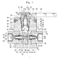
- Fig. 1 illustrates one embodiment of a trunnion ball valve for high pressure of the present invention
- Fig. 2 illustrates an exploded cross sectional view of Fig. 1 .
- a ball valve main unit (hereinafter referred to as valve main unit) 10 of the present invention includes a ball 12 serving as a ball, in a rotatable manner via a stem 11, and a seal mechanism 13 disposed on both sides of the ball 12 for providing seal contact with the ball 12, and has a configuration of a trunnion ball valve particularly suitable for flowing high-pressure fluid therein.
- the valve main unit 10 includes a body main unit 14.
- the body main unit 14 includes a body 15 and cap members 16, 16, which are provided on a primary side and a secondary side of the body 15, respectively.
- the ball 12 and the seal mechanism 13 are disposed inside the body main unit 14.
- High pressure in the present embodiment is for example 35 MPa or higher, and is assumed to be from 70 to 105 MPa, more specifically 90 MPa in piping facilities for a hydrogen station.
- the body 15 is formed in a substantially quadrangular shape.
- the cap members 16, 16 are screwed onto both sides of the body 15 via screwing sections 16a, respectively, in a state in which a gasket 17 is sandwiched between the body 15 and the cap members 16, 16.
- the cap members 16 have on its inner peripheral surface a mounting hole 19 for mounting the seat retainer 18, and the mounting hole 19 is opened so as to enable insertion of the seat retainer 18. Furthermore, the mounting hole 19 can mount a sealing member 20.
- the mounting hole 19 has a diameter expanded groove section 23 that has a diameter more expanded than that of the mounting hole 19, and a spacer 25 shaped in a substantially tubular shape is provided between the diameter expanded groove section 23 and a spring member 22 later described.
- the spring member 22 is provided in an elastic state between the spacer 25 and the seat retainer 18.
- an internal thread section 24 is formed in communication with the mounting hole 19.
- an external joint not illustrated can be screwed.
- the cap members 16 can be integrated with the body 15 by bonding means such as adhesion or welding.
- the ball 12 is made of stainless steel such as SUS316 as its base material.
- the ball 12 has a ball surface 12a, and the seat retainer 18 can be sealed onto the ball surface 12a.
- the ball 12 has a shaft section (upper shaft section) 12b at an upper part thereof and a trunnion (lower shaft section) 12c at a lower part thereof, and the ball 12 is made rotatable by applying the upper shaft section 12b and the lower shaft section 12c in an application hole 15a of the body 15.
- fluid flows while a communication hole 12d formed inside the ball 12 communicates with an inner flow channel 28 formed inside the seat retainer 18.
- the base material of the ball 12 is SUS316
- Vickers hardness is Hv200 or less.
- the ball 12 is a water contact part, so therefore it is preferable to use materials that do not become brittle by hydrogen.
- a pressure equalizing hole 12e is opened that communicates from the communication hole 12d to the upper surface of the ball. Through this pressure equalizing hole 12e, pressure within the cavity while the valve is opened can be released.
- the seal mechanism 13 is made up of the seat retainer 18, the spring member 22 and the sealing member 20.
- the seat retainer 18 is made of copper based alloy such as BeCu alloy (beryllium copper alloy) serving as base material thereof.
- BeCu alloy beryllium copper alloy
- a case in which, in particular, BeA-25 (beryllium copper) to which solution treatment, cold working and hardening treatment (heat treatment) are carried out is used as the base material of the seat retainer 18, sealing ability is exhibited as a result of containing a relatively soft copper component while the strength of stainless steel SUS630 or more is maintained.
- the Vickers hardness after carrying out the heat treatment is in a range of Hv 360 to 450
- mechanical property of beryllium copper is, for example, a tensile strength of 1200 to 1500 MPa, and 0.2% proof stress of 1000 to 1400 MPa.
- embrittlement caused by hydrogen will also be prevented.
- the sealing surface 18a which surface is a side to be in contact with the ball surface 12a.
- base material hardness of the seat retainer 18 is set higher than base material hardness of the ball 12, and satisfies the following relationship: "hardness of diamond-like carbon” > “base material hardness of seat retainer” > “base material hardness of ball”.
- the sealing ability is more maintained by use of BeCu for the seat retainer 18, as described above.
- the base material hardness of the ball can be set the same or higher than the base material hardness of the seat retainer.
- the seat retainer 18 is shaped to have a diameter expanded section 26 disposed so as to face the ball 12, and a tube section 27 having a smaller diameter than the diameter expanded section 26.
- the sealing surface 18a is provided on the diameter expanded section 26 on the surface facing the ball 12, and the sealing surface 18a and the ball surface 12a can be in contact in a sealing manner.
- the base material of the seat retainer 18 can be copper alloy such as aluminum bronze or material other than copper based alloy.
- BeCu alloy having high mechanical property is used in order to prevent deformation thereof, since the tube section of the seat retainer 18 that is a pressure resistant sliding component has a small diameter and a thin wall.
- Fig. 3 describes a case of providing the sealing surface 18a of the seat retainer 18.
- the drawing provides an X-axis from a spherical diameter center P of the ball surface 12a in a flow channel direction of the ball 12, and a Y-axis intersecting the X-axis.
- Two deviation points (offset point) Q, Q are provided in the Y-axis direction from the spherical diameter center P, having a predetermined distance H between the two points.
- Semispherical surfaces S, S having a radius R slightly longer than a radius R B of the ball surface 12a are drawn from the offset points Q, Q in opposite directions to the deviation (offset) sides by an angle of 180°, to structure the sealing surface 18a having a part of the semispherical surface S serve as a trajectory surface. That is to say, in Fig. 4 , the sealing surface 18a is a part of a trajectory of the slightly longer radius R of the ball surface 12a drawn from the offset points Q, Q of the predetermined distance H, and the sealing surface 18a is drawn based on the radius R.
- the predetermined distance H of the offset points Q is set so that a sealing position T on the sealing surface 18a with the ball surface 12a comes in a substantially center position of the sealing surface 18a.
- an inner flow channel diameter d N of the ball 12 is 10 mm and a spherical diameter D B of the ball surface 12a is ⁇ 20 mm (radius R B is 10 mm)
- the offset point Q having the distance H be ⁇ h is set as the slightly long radius R (radius R B + Ar), and the trajectory surface is drawn from this offset point Q.
- the predetermined distance H from the spherical diameter center P of the offset point Q can be changed as appropriate in accordance with the spherical diameter of the ball surface 12a. In the present embodiment, it is set so as to satisfy the following relationship: ⁇ r> ⁇ h.
- the sealing surface 18a of the seat retainer 18 is set as a slightly longer radius than the ball surface 12a without providing the offset point Q, the ball 12 comes in contact with an inner peripheral part of the sealing surface 18a of the seat retainer 18. This causes the inner peripheral part to locally contact the ball surface 12a, thereby increasing the possibility of damaging DLC. In order to avoid this, a technique of rounding the inner peripheral part to avoid the local contact can also be considered. This however causes the shift in position of the ball 12 in the X-axis direction, and would cause new problems such as the need of narrowing the shaft section at an upper part of the ball 12.
- the sealing position of the sealing surface 18a of the seat retainer18 with the ball surface 12a is made to be positioned substantially center of the sealing surface. Additionally, sealing is carried out by surface contact sealing the seat retainer 18 with the ball 12, by carrying out a finishing process to the ball 12 prior to processing DLC.
- the present invention has a sealing surface made to be in contact by line contact or surface contact.
- line contact in practice, the present invention forms a contacting sealing surface having a predetermined width.
- a width of a surface contact seal is a ring-shaped fitted part formed substantially parallel to the Y-axis, and for example has a width of approximately 0.5 mm. Since the trunnion ball valve of the present embodiment is for high pressure, the ball 12 changes in place due to the fluid pressure, however by setting the surface contact sealing width as described above, the ring-shaped fitted part is maintained. Furthermore, as illustrated in Fig. 4 , the sealing position T is set at a substantially center position of the sealing surface 12a. Therefore, even if the position of the sealing position T shifts slightly during use of the ball valve, the ring-shaped fitted state will be maintained.
- the sealing member 20 and back up rings 29 and 30 later described are arranged to the tube section 27 of the seat retainer 18.
- the tube section 27 is fitted into the mounting hole 19 of the cap members 16, to allow movement of the seat retainer 18 in the flow channel direction.
- the sealing member 20 is attached to an outer surface of the tube section 27 in an adhered state, and when the seat retainer 18 moves in the flow channel direction, the tube section 27 and the mounting hole 19 are sealed by the sealing member 20.
- an inner flow channel 28 in which high-pressure fluid flows is formed inside the seat retainer 18.
- a coating layer 31 made of diamond-like carbon is provided to at least both of the sealing surface 18a of the seat retainer 18 and the ball surface 12a that is in contact with the sealing surface 18a, to allow exhibition of sliding ability and sealing performance between the seat retainer 18 and the ball 12.
- a conforming layer 32 is provided on the coating layer 31 of one or both of the sealing surface 18a and/or the ball surface 12a.
- DLC is an amorphous hard film mainly made of hydrocarbon or an allotrope of carbon, has high hardness, and has excellent properties such as lubricity, wear and abrasion resistance, surface smoothness, and chemical stability. DLC can be deposited as a film by plasma CVD method or PVD method.
- source gas is made into a form of plasma inside a chamber with use of hydrocarbon gas such as acetylene, and vapor-phased hydrocarbon is deposited on the surface of the component.
- hydrocarbon gas such as acetylene
- vapor-phased hydrocarbon is deposited on the surface of the component.
- hydrogen is contained in the source, so therefore DLC will also contain hydrogen.
- examples include a sputtering technique and an ion plating technique.
- graphite that serves as the source is exposed to ion beams, arc discharge, glow discharge and the like under vacuum, and dispersed carbon atoms are adhered to the surface of the component.
- DLC is provided just using carbon, thereby allowing providing a DLC free of hydrogen.
- DLC of the present embodiment contains hydrogen, and thus DLC will not peel off from the base material.
- DLC process is carried out to the entire surface of the ball surface 12a for the ball 12, and to the thick lined parts illustrated in Fig. 3 for the seat retainer 18.
- the conforming layer 32 is provided if necessary in an appropriate thickness.
- a component on which the DLC coating layer 31 is provided is usable as a high surface pressure sliding component. Furthermore, by providing the conforming layer 32, initial comformability improves.
- the spring member 22 in the seal mechanism is constituted of, for example, a coil spring, and is provided between the diameter expanded section 26 of the seat retainer 18 fitted inside the mounting hole 19, and a spacer 25.
- the spring member 22 applies elastic force in the sealing surface 18a direction of the seat retainer 18.
- the spring member 22 may also be a disc spring.
- the sealing member 20 is constituted of, for example, a rubber O-ring, and is fitted into the mounting hole 19 together with the back up rings 29 and 30. As a result, the sealing member 20 is disposed between the mounting hole 19 on the body main unit 14 side and the outer surface 18a of the seat retainer 18.
- the back up ring 29 disposed on the sealing member 20 side is formed by, for example. PTFE (polytetrafluoroethylene), and the back up ring 30 disposed on the outside of the back up ring 29 is formed of, for example, PEEK (polyetheretherketone).
- Each of the sealing member 20 and the back up rings 29 and 30 may be made of material of different properties other than those described above, however even in those cases, it is preferable to use a soft material of a same degree as rubber or PTFE. By use of soft material, it is possible to change the shape of them, thereby making it easier to fit to the mounting hole 19.
- the sealing member 20 is fitted to the mounting hole 19 in a state in which the back up rings 29 and 30 are disposed on either sides. Both sides of the sealing member 20 are protected by the back up rings 29 and 30.
- valve main unit 10 is configured to seal high-pressure fluid by what is called a double sealing method, by the elastic force applied by the spring member 22 to the seat retainer 18 and an autofrettage force generated by exhibiting pressed force of the seal mechanism 13 by fluid pressure set in an inside diameter side of the sealing member 20.
- the outer peripheral side of the stem 11 has a lower packing washer 33, an inside diameter sealing member 34, an outer diameter sealing member 35, a thrust bearing 36, an upper packing washer 37 that can be fitted from an upper side of the lower packing washer 33, a gland 38 and a bush 39.
- the stem 11 is attached rotatable inside the body 15 via these members.
- the lower packing washer 33 includes a cylinder section 40 in which the inside diameter sealing member 34 that seals a space between the stem 11 is housed, and a bottom section 41 for mounting the inside diameter sealing member 34.
- a ring-shaped groove 42 is formed on an outer peripheral side of the cylinder section 40, and the outer diameter sealing member 35 is attached on the ring-shaped groove 42.
- the lower packing washer 33 is provided on an upper side of the stem 11 via the thrust bearing 36. This thus allow for the stem 11 to be rotatable with respect to the inside diameter sealing member 34 and the upper packing washer 37 via the thrust bearing 36.
- the gland 38 is formed in a substantially tubular shape, and includes a ring-shaped flange section 43 into which the upper packing washer 37 and the lower packing washer 33 can be fitted, and a lid section 45 that provides a lid for the upper packing washer 37 from above.
- the gland 38 is attached from the upper side of the upper packing washer 37 by screwing onto a mounting recess section 46 provided on the body 15, and houses the inside diameter sealing member 34.
- the upper and lower packing washers 37 and 33 on which the outer diameter sealing member 35 is attached is pressed in the direction of the thrust bearing 36.
- the gland 38 has the bush 39 attached on an inner peripheral side thereof, and the bush 39 causes the upper packing member 37 to be pressed against the lower packing washer 33.
- the bush 39 is provided made of material for example PEEK.
- the body 15 of the valve main unit 10 has a cover 50 attached, and via the cover 50, a handle cap 51 and a manual handle 52 are provided.
- the cover 50 is formed in a substantially disc shape, and has on its bottom surface side a flange-like side surface section 54 that can be fitted to a ring-shaped protrusion 53 formed on an upper surface side of the body 15.
- the side surface section 54 has two each of a counterbore section 55 and a notch 56 in intervals of 90°, provided in an alternate manner.
- the cover 50 has in its center section a hole 57 for inserting the handle cap 51.
- the hole 57 has a regulating piece (not illustrated) formed in a protruding manner, and this regulating piece regulates the rotation of the stem 11 to within a range of 90°.
- the handle cap 51 is formed in a substantially cylindrical shape with a substantially same diameter as the gland 38, and its outer peripheral side has a locking piece 59 in a protruding manner, which allows for locking with a regulating piece on the cover 50.
- the handle cap 51 has on its bottom side a fitting hole 51a that can fit the parallel section 11a formed on an upper end section of the stem 11.
- the handle cap 51 is integrated to the stem 11 by fitting the parallel section 11a into the fitting hole 51a.
- the handle cap 51 has an attachment hole 60, while an attached part of the handle 52 is provided to an outer diameter that can be fitted into the attachment hole 60.
- an internal thread 61 is provided thereon.
- the internal thread 61 allows for a secured bolt 62 and a locking screw (not illustrated) to be screwed thereon.
- the handle cap 51 is provided in a predetermined direction with respect to the stem 11 by fitting the parallel section 11a into the fitting hole 51a, and the cover 50 is fit and attached to the ring-shaped protrusion 53 from above the handle cap 51 in this state. Furthermore, the handle cap 51 is fixed by having the securing bolts 62 be screwed into the internal thread 61 via the counterbore section 55 of the cover 50 and the locking screw be screwed to the internal thread 61 via the notch 56 of the cover 50.
- the handle 52 is attached operable on an upper end side of the stem.
- the locking piece 59 is regulated by being in contact with the regulating piece. This enables opening and closing operation while regulating the rotation of the stem 11 to 90°.
- valve main unit 10 is provided as a manual valve.
- trunnion ball valve for high pressure of the present invention can be automated by use of an automatic operation actuator such as a pneumatic actuator as described later, other than attaching a manual handle as described above.
- the trunnion ball valve for high pressure of the present invention exhibits sliding ability and sealing performance by providing a coating layer 31 of diamond-like carbon to at least both of the sealing surface 18a of the seat retainer 18 and the ball surface 12a with which the sealing surface 18a is in contact. Accordingly, it is possible to maintain the sliding ability achieved by high surface pressure when high-pressure fluid such as high pressure hydrogen gas flows to prevent any damage on any sides of the seat retainer 18 and the ball 12, while securing low torque and sealing ability for improving operability while securely preventing leakage.
- the coating layer 31 having a DLC film thickness of 2 to 3 ⁇ m, it is possible to maintain ultraprecision machining of the base material such as sphericity and finished roughness even after the coating process.
- the sealing surface 18a is configured so that a part of a semispherical surface S drawn so as to have a radius R slightly longer than a radius R B of the ball surface 12a in an angle of 180° in a direction opposite to the offset side, from the offset point Q offset in a predetermined distance H in a Y-axis direction that intersects with an X-axis (in the flow channel direction of the ball 12 from the spherical diameter center P of the ball surface 12a), serve as a trajectory surface.
- the sealing position T on the sealing surface 18a with the ball surface 12a is made to be in a substantially center position of the sealing surface 12a, so as to prevent the ball surface 12a from being in contact with the sealing surface 18a in an inclined state to improve the sealing ability by pressure welding the ball surface 12a to the sealing surface 18a, thereby securely preventing leakage.
- the base material hardness of the seat retainer 18 is set higher than the base material hardness of the ball 12 to improve the durability of the seat retainer 18 and allowing for preventing any damage caused by galling due to rotation of the ball 12 and the like. As a result, high sealing ability is exhibited.
- the base material of the seat retainer 18 be BeCu alloy and the base material of the ball 12 be stainless steel, employment of such metal seat allows for reducing a given effect caused by temperature change of hydrogen, thereby improving durability. Even in a case in which the DLC coating layer 31 wears out, leakage can be avoided by a beryllium layer of the BeCu alloy, that is the base material of the seat retainer 18.
- the conforming layer 32 is provided on the surface of the coating layer 31 on either one or both of the sealing surface 18a and the ball surface 12a. This increases the conformability between the sealing surface 18a and the ball surface 12a, thereby preventing wearing due to abrasion while improving sliding ability. Furthermore, the degree of adhesion improves by the conforming layer 32, thereby improving the sealing ability.
- the valve main unit 10 of the present invention sets fluid pressure on the inside diameter side of the seat retainer 18 of the seal mechanism 13. Accordingly, it is possible to obtain the following autofrettage force.
- a left side of the seat retainer 18 is named a primary side and a right side thereof is named a secondary side.
- the following relationship is set, provided that an inside diameter ⁇ A is of the sealing surface 18a, an inside diameter cpD is of the sealing member 20, an outer diameter cpC is of the sealing surface 18a, and an outer diameter cpB is of the sealing member 20: inside diameter cpD ⁇ inside diameter ⁇ A ⁇ outer diameter ⁇ C ⁇ outer diameter ⁇ B. Therefore, regarding the autofrettage force on the primary side, the seat retainer 18 is pressed to the ball 12 by fluid pressure inside the flow channel applied on an area of inside diameter cpD - inside diameter ⁇ A while the valve is closed.
- the seat retainer 18 is pressed to the ball 12 by fluid pressure inside a cavity applied on an area of outer diameter cpC - inside diameter cpD.
- the trunnion ball valve for high pressure of the present invention can securely seal high-pressure fluid by exhibiting excellent self-sealing abilities attained by synergy of the double sealing method of the elastic force of the spring member 22 described above and the autofrettage force.
- Fig. 6 illustrates a second embodiment of a trunnion ball valve of the present invention
- Fig. 7 illustrates a main part of Fig. 6
- Fig. 8 illustrates a cross section of line A-A in Fig. 7 .
- the drawings illustrate a fitted state of the stem and the ball. It should be noted that in this embodiment, parts identical to the above embodiment are represented by identical reference signs, and explanations thereof are omitted.
- the trunnion ball valve for high pressure of this embodiment provides the ball 12 in an integrated manner with the upper shaft section 12b and the lower shaft section 12c as like the above embodiment, as illustrated in Fig. 7 .
- the ball 12 is disposed rotatable via radial bearings 110, 110 on an outer periphery of the upper shaft section 12b and the lower shaft section 12c.
- the radial bearings 110 are coated with a soft member 110b such as polytetrafluoroethylene (PTFE) on an inner surface of a rigid cylindrical body 110a such as stainless steel.
- PTFE polytetrafluoroethylene
- the upper shaft section 12b and the lower shaft section 12c of the ball 12 are supported by a pair of the cylindrical radial bearings 110, 110.
- the radial bearings 110 are set as a long shape that supports from the vicinity of a spherical section of the ball 12 to the vicinity of the stem connection section.
- the present embodiment is of a top-entry type structure in which the ball 12 is inserted from the upper section of the body 15, the present invention is applicable to a bottom-entry type in which the ball 12 is inserted from the lower section of the body 15.
- the stem 11 is joint to the upper shaft section 12b of the ball 12, and the ball 12 is provided rotatable through the rotational force of the stem.
- the stem 11 has a sliding surface 103 in a thrust direction, and a thrust bearing 105 is provided between the sliding surface 103 and the lower packing washer 33.
- the thrust bearing 105 is a member on which PTFE is coated on a rigid plate such as a thin stainless steel plate not illustrated.
- the sliding surface 103 and the lower packing washer 33 of the stem 11 are to be in contact with the PTFE.
- the stem 11 is made to be a bearing in the thrust direction via the thrust bearing 105.
- a parallel two-surface groove 102 is provided on a lower end of the stem 11.
- the parallel two-surface groove 102 is provided so as to be cut out in a direction on which load is received while the valve of the ball 12 is closed, that is to say, in a horizontal direction in Fig. 7 .
- a parallel two-surface section 101 that can be joint to the parallel two-surface groove 102 is provided on an upper end of the upper shaft section 12b of the ball 12.
- the stem 11 and the ball 12 are provided capable of operating together by the joint parallel two-surface groove 102 and parallel two-surface section 101.
- the thrust bearings 105 and the radial bearings 110 are determined in position and fixed, by being pushed from an upper side by the gland 38 screwed to the body 15. At this time, an upper side of the stem 11 is supported by the bush 39 for pressing, which bush is attached on the inner peripheral side of the gland 38, and the inside diameter sealing member 34 and outer diameter sealing member 35 are attached to their set positions.
- the recess and projecting relationship can be opposite, that is to say, the stem 11 may have the projecting parallel two-surface section and the ball 12 may have the recessed parallel two-surface groove.
- the trunnion ball valve for high pressure has, as illustrated in Fig. 6 and Fig. 9 , a pneumatic actuator 82 for automatic operation, on the stem upper end 11b.
- the trunnion ball valve for high pressure of the present invention can be a manually operated ball valve in which a handle 52 for manual operation is provided on the upper end 11b of the stem 11 as described above, or can be an automatically operated ball valve in which the upper end 11b of the stem 11 is connected to an automatically operating actuator 82 mounted on the body main unit 15.
- the actuator 82 is attached to the body main unit 15 via the cover 50.
- the actuator 82 allows for accurately controlling rotation of the ball 12 supported in a perpendicular state in the secondary direction, by a predetermined torque.
- the cover 50 is composed of a substrate 84 having an attachment opening 83, and a hanging plate 85.
- the substrate 84 has a bolt passage hole 86
- the hanging plate 85 has a position determination groove 87 and a counterbore hole 88 each opened at intervals of 90° in an alternate manner. Accordingly, the position determination groove 87 and the counterbore hole 88 are provided in two positions each with respect to the hanging plate 85.
- An outer periphery of an upper part of the shaft mounting section 80 of the body 15 in the ball valve main unit 10 has a notch provided in a ring shape, thereby forming a ring-shaped protrusion 90.
- On an outer surface of the ring-shaped protrusion 90 four internal thread sections 93 each in which a valve fixing bolt 91 and an attachment pin 92 can be screwed are provided at intervals of approximately 90°, at even positions.
- a housing groove 94 is provided on an upper surface of the ring-shaped protrusion 90, and the housing groove 94 is capable of housing a head 96 of an actuator fixing bolt 95 for fixing the actuator 82 to the cover 50.
- a ring-shaped protrusion 97 is formed that can be fitted into the attachment opening 83 opened on the cover 50, and on the bottom surface side of the actuator 82, an internal thread not illustrated is provided, which internal thread allows for screwing an actuator fixing bolt 95 therein.
- the actuator 82 is mounted on a predetermined position of the shaft mounting section 80 by locking the attachment pin 92 provided on an outer surface of an upper part of the shaft mounting section 80 to the position determination groove 87 to determine and fix its position, while fitting the ring-shaped protrusion 90 to the inner periphery of the hanging plate 85, and thereafter placing the cover 50 on the upper surface of the shaft mounting section 80.
- a projected section 122 formed on an upper end of the stem 11 is fitted to a recess section 121 formed on a lower edge of the output shaft 120 provided on the actuator 82, to connect the output shaft 120 with the stem 11.
- the head 96 of the actuator fixing bolt 95 is housed in a housing groove 94 on the upper surface of the shaft mounting section.
- valve fixing bolt 91 is screwed onto the internal thread section 93 from the hanging plate 85, to determine the position of and fix the cover 50 to the ball valve main unit 10, and via this cover 50, it is possible to accurately determine the position of and fix the actuator 82 to the predetermined position of the ball valve main unit 10. While the actuator 82 is operating, it is possible to accurately open and close the ball 12. It should be noted that the valve fixing bolt 91 can be provided at four positions, instead of the position determination pin.
- the actuator 82 is what is called a spring return type.
- a spring member 115 is provided inside, and a retainer member 116 is provided to prevent the springing out of the spring member 115.
- the retainer member 116 has a projecting striking section 117, and when a piston 118 provided inside reciprocates inside a cylinder 119, this striking section 117 comes into contact with both sides inside the cylinder 119. This regulates a stroke (not illustrated) of the piston 118, and regulates a rotational angle of the output shaft 120 to a predetermined angle, that is to say, to 90°.
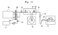
- Fig. 11 illustrates a hydrogen station in which a trunnion ball valve for high pressure of the present invention is provided.
- the hydrogen station includes an accumulator 70, a compressor 71, a dispenser 72, a precooling heat exchanger 73, a quick joint 74, a filling hose 75, a filling nozzle 76, and an in-vehicle tank 77, and these components constitute a system as a supply line 78 for high pressure hydrogen.
- the ball valve of the present invention has small pressure loss. Therefore the pressure loss of the entire system is reduced by providing the ball valve on a secondary side of the accumulator 70 or by providing the ball valve on other supply lines, and is suitable for a system illustrated in Fig. 10 .
- a manual valve 81 is provided on connection parts of each unit in the hydrogen station, and an automated valve 80 is appropriately provided on a primary or secondary side of each unit to control the opening and closing thereof.
- the accumulator 70 includes a plurality of separate tanks inside. By appropriately switching between valves 80 that connect the tanks with the compressor 71 and valves 80 that connect the tanks with the dispenser 72, hydrogen is supplied to the dispenser from a tank with a predetermined pressure, while tanks having a lower pressure than a predetermined low limit pressure are filled with hydrogen from the compressor 71 to achieve the predetermined pressure.
- the supply of hydrogen in the system is controlled by a predetermined program, and the supply of hydrogen is controlled as appropriate in accordance with a vehicle supplied amount.
- Fig. 10 is a longitudinal sectional view illustrating another embodiment of the trunnion ball valve for high pressure.
- Fig. 1 illustrates a top-entry type ball valve
- Fig. 10 illustrates a bottom-entry type ball valve.
- the ball valve configuration illustrated in Fig. 10 includes identical configurations as the configuration of the ball valve illustrated in Fig. 1 to Fig. 9 , and such identical parts are represented by identical reference signs and their explanations are omitted.
- the cap members 16, 16 are fixed by screwing onto the primary side and secondary side of a body 150, respectively, each via a screwing section 16a. Moreover, to an attachment hole 150a of the body 150, a ball having a stem 11, an upper shaft section 12b and a lower shaft section 12c is inserted from a bottom side of the body 150. The ball is fixed to a protrusion 203 of the body 150 via a screwing section 200 by use of a fixing screw 202 that has a fastening section 201, to configure a bottom-entry type ball valve.
- a packing 206 having a cross section of a substantially U-shape, a metal bush 205, a bearing 204, and radial bearings 110 (110a, 110b) are attached, and 207 in the drawing illustrates space.
- a hydrogen durability test was conducted to the ball 12 and the seat retainer 18 of the trunnion ball valve for high pressure of the present invention, and their durability were compared.
- the ball 12 was operated to open and close while high-pressure fluid whose heat cycle was at temperatures in a range of -40 °C to 85 °C was flown, under temperature of normal temperature, low temperature (-40 °C), and high temperature (85 °C). Hydrogen gas was used as the high-pressure fluid.
- the ball 12 was operated to open and close 40,000 times under the conditions. As a result, no abnormalities were found in either of the sliding ability or sealing performance. Although a pressure difference of 90 MPa occurred when high-pressure fluid was flown, an operation torque at this time was held down to for example 9.4 N ⁇ m, which is a rated pressure of the actuator. Accordingly, it can be said that high operability was maintained.
- the present invention is particularly used suitably in piping facilities such as a hydrogen station in which high-pressure fluid hydrogen and the like that is used in fuel cells flows, however the present invention can exhibit excellent sealing ability and torque for any pipeline through which high-pressure fluid flows.
- the present invention is suitable for a valve in a CNG (Compressed Natural Gas) station, or alternatively as a ball valve for high pressure that is used in various locations through which high-pressure fluid flows, such as a pipeline valve.
Landscapes
- Engineering & Computer Science (AREA)
- General Engineering & Computer Science (AREA)
- Mechanical Engineering (AREA)
- Taps Or Cocks (AREA)
- Fuel Cell (AREA)
Applications Claiming Priority (3)
| Application Number | Priority Date | Filing Date | Title |
|---|---|---|---|
| JP2012041912 | 2012-02-28 | ||
| JP2012192124 | 2012-08-31 | ||
| PCT/JP2013/055367 WO2013129560A1 (ja) | 2012-02-28 | 2013-02-28 | 高圧用トラニオン型ボール弁並びに水素ステーション |
Publications (3)
| Publication Number | Publication Date |
|---|---|
| EP2821680A1 true EP2821680A1 (de) | 2015-01-07 |
| EP2821680A4 EP2821680A4 (de) | 2015-11-11 |
| EP2821680B1 EP2821680B1 (de) | 2018-05-09 |
Family
ID=49082751
Family Applications (1)
| Application Number | Title | Priority Date | Filing Date |
|---|---|---|---|
| EP13754623.0A Active EP2821680B1 (de) | 2012-02-28 | 2013-02-28 | Zapfenkugelventil für hochdruck und wasserstoffstation |
Country Status (8)
| Country | Link |
|---|---|
| US (1) | US9546736B2 (de) |
| EP (1) | EP2821680B1 (de) |
| JP (2) | JP6072763B2 (de) |
| KR (1) | KR102039532B1 (de) |
| CA (1) | CA2862411C (de) |
| DK (1) | DK2821680T3 (de) |
| NO (1) | NO2821680T3 (de) |
| WO (1) | WO2013129560A1 (de) |
Cited By (2)
| Publication number | Priority date | Publication date | Assignee | Title |
|---|---|---|---|---|
| CN105065760A (zh) * | 2015-08-03 | 2015-11-18 | 海特克液压有限公司 | 一种手动阀的拨杆回中装置 |
| WO2018137913A1 (de) * | 2017-01-27 | 2018-08-02 | Robert Bosch Gmbh | Magnetventil, brennkraftmaschine mit magnetventil und verfahren zur herstellung eines magnetventils |
Families Citing this family (35)
| Publication number | Priority date | Publication date | Assignee | Title |
|---|---|---|---|---|
| KR101579600B1 (ko) * | 2014-05-08 | 2015-12-22 | 김충호 | 개폐가 용이한 유체 밸브 장치의 제작 방법 및 이에 의하여 제작된 유체 밸브 장치 |
| JP6352699B2 (ja) * | 2014-06-30 | 2018-07-04 | 株式会社キッツ | ボールバルブ用ボールシートの固着構造とその固着方法及びトラニオン型ボールバルブとこのバルブを用いた水素ステーション |
| ES2813378T3 (es) | 2014-10-28 | 2021-03-23 | Kitz Corp | Válvula de bola de tipo Trunnion |
| JP6426435B2 (ja) * | 2014-10-28 | 2018-11-21 | 株式会社キッツ | トラニオン型ボールバルブ |
| US10718468B2 (en) | 2015-04-24 | 2020-07-21 | Cmd Corporation | Method and apparatus for dispensing gaseous fuel to a vehicle |
| JP6755521B2 (ja) * | 2016-02-18 | 2020-09-16 | 日本碍子株式会社 | 熱交換部材、熱交換器及び熱交換部材の使用方法 |
| US20170286654A1 (en) * | 2016-03-29 | 2017-10-05 | Coverquick, Inc. | System and method for smart weapon implementation and deployment |
| FR3052526B1 (fr) * | 2016-06-13 | 2018-11-23 | Valeo Systemes De Controle Moteur | Vanne de controle d'un debit de fluide |
| JP6784577B2 (ja) * | 2016-11-15 | 2020-11-11 | 日立オートモティブシステムズ株式会社 | 制御弁 |
| JP6865623B2 (ja) * | 2017-04-14 | 2021-04-28 | 株式会社キッツ | 高圧用トラニオン型ボール弁およびこれを用いた水素ステーション |
| JP7141633B2 (ja) * | 2017-05-12 | 2022-09-26 | 京セラ株式会社 | 摺動装置 |
| CN107420573B (zh) * | 2017-06-26 | 2023-11-24 | 开封瑞科阀门有限公司 | 一种预紧补偿移动阀座耐高温高压双向硬密封旋球阀 |
| KR101825220B1 (ko) * | 2017-08-07 | 2018-02-02 | (주)케이에스티플랜트 | 마이크로합금화 층이 형성된 메탈시트 볼밸브 장치 및 그 제작 방법 |
| EP3695145B1 (de) | 2017-10-10 | 2024-03-06 | Cameron Technologies Limited | Konturierter integrierter sitz für ein kugelventil |
| RU181391U1 (ru) * | 2017-11-07 | 2018-07-11 | Федеральное государственное бюджетное образовательное учреждение высшего образования "Кубанский государственный технологический университет" (ФГБОУ ВО "КубГТУ") | Шиберная задвижка с многослойным покрытием |
| RU184991U1 (ru) * | 2017-12-27 | 2018-11-15 | Алексей Сергеевич Тимохин | Шаровой кран |
| RU184990U1 (ru) * | 2017-12-27 | 2018-11-15 | Алексей Сергеевич Тимохин | Шаровой кран |
| US10900579B2 (en) * | 2018-03-21 | 2021-01-26 | Paul M. Cordua | Riser valve manifold |
| CN108644456A (zh) * | 2018-05-16 | 2018-10-12 | 芜湖市艾德森自动化设备有限公司 | 一种高密封防锈蚀阀杆 |
| US10816102B2 (en) * | 2018-08-01 | 2020-10-27 | General Electric Company | Erosion resistant steam valve |
| JP7213033B2 (ja) * | 2018-08-06 | 2023-01-26 | 株式会社キッツエスシーティー | 高圧用トラニオン型ボール弁及びこれを用いた水素ステーション |
| CN108999994B (zh) * | 2018-10-10 | 2020-09-08 | 江山市志成阀门有限公司 | 一种球阀的加工工艺 |
| US12259064B2 (en) * | 2018-11-01 | 2025-03-25 | Oil States Energy Services, L.L.C. | Valve with pressure differential seating |
| US10995871B2 (en) | 2018-11-07 | 2021-05-04 | Cameron International Corporation | Hard and lubricious valve surfaces, material compositions and sequences of manufacturing |
| JP7381273B2 (ja) * | 2019-09-27 | 2023-11-15 | 株式会社キッツエスシーティー | ボールバルブ及びボールバルブとアクチュエータの直付方法 |
| CN110778737B (zh) * | 2019-10-16 | 2024-08-13 | 得威阀门有限公司 | 多道密封面衬氟球阀 |
| KR102292754B1 (ko) * | 2020-06-25 | 2021-08-25 | 티에스모스트 주식회사 | 볼 밸브 |
| CN111911649B (zh) * | 2020-07-17 | 2022-03-11 | 沈阳航天新光集团有限公司 | 气动球阀 |
| CN112361025B (zh) * | 2020-11-25 | 2021-08-06 | 浙江石化阀门有限公司 | 一种快开高温球面密封切断阀的快开机构 |
| US11686404B2 (en) * | 2020-12-11 | 2023-06-27 | Dresser, Llc | Reducing noise in ball valves |
| KR102259180B1 (ko) * | 2021-01-05 | 2021-05-31 | 김충호 | 밸브등급 4500 이하의 고온 및 고압 유체용 분해정비형 메탈 볼밸브 |
| GB2605945B (en) * | 2021-03-15 | 2026-03-11 | Jb Valves Ltd | Valve apparatus |
| CN113757401B (zh) * | 2021-09-07 | 2022-04-22 | 哈电集团哈尔滨电站阀门有限公司 | 一种能够防止楔死的手动楔式闸阀 |
| CN115451148B (zh) * | 2022-09-21 | 2025-09-26 | 慎江阀门有限公司 | 一种耐磨球阀及碳化钨、dlc复合涂层的喷涂方法 |
| KR102763878B1 (ko) * | 2022-10-06 | 2025-02-07 | 김성탄 | 수소 디스펜서 |
Family Cites Families (19)
| Publication number | Priority date | Publication date | Assignee | Title |
|---|---|---|---|---|
| US3047007A (en) * | 1959-04-01 | 1962-07-31 | Lunkenheimer Co | Ball valve |
| US3174495A (en) * | 1962-11-16 | 1965-03-23 | Acf Ind Inc | Fire safe ball valve |
| US4572239A (en) * | 1981-08-28 | 1986-02-25 | Whitey Co. | High pressure ball valve |
| JPH02286973A (ja) * | 1989-04-28 | 1990-11-27 | Keihin Seiki Mfg Co Ltd | ボール弁 |
| US5127628A (en) * | 1991-11-04 | 1992-07-07 | Fike Corporation | Means for rotating ball valves between open and closed positions |
| DE4436202A1 (de) * | 1994-09-29 | 1996-04-11 | Rautenkranz Int Hermann | Kellyhahn mit doppelt gelagertem Kugelküken |
| JPH08178091A (ja) * | 1994-12-27 | 1996-07-12 | Kyocera Corp | ディスクバルブ |
| JP3118764B2 (ja) * | 1995-03-24 | 2000-12-18 | 株式会社キッツ | ボールバルブ |
| JP3601554B2 (ja) * | 1995-08-11 | 2004-12-15 | アイシン・エィ・ダブリュ株式会社 | 電磁式圧力調整弁 |
| JP2004076884A (ja) | 2002-08-21 | 2004-03-11 | Konan Electric Co Ltd | 高硬度用ボール弁 |
| KR20040082743A (ko) * | 2003-03-20 | 2004-09-30 | 안정오 | 개폐밸브용 볼의 제조방법 및 그 볼 |
| US7025329B2 (en) | 2004-04-30 | 2006-04-11 | Sequal Technologies, Inc. | Needle valve for flow control |
| US8146889B2 (en) * | 2004-08-27 | 2012-04-03 | Vetco Gray Inc. | Low friction coatings for dynamically engaging load bearing surfaces |
| JP2006144920A (ja) * | 2004-11-19 | 2006-06-08 | Flo-Tec Ltd | ボールバルブ |
| CA2619331A1 (en) * | 2007-01-31 | 2008-07-31 | Scientific Valve And Seal, Lp | Coatings, their production and use |
| US20100200791A1 (en) | 2009-02-07 | 2010-08-12 | Victaulic Company | Valve Having High Pressure and Low Pressure Seals |
| JP2011001598A (ja) * | 2009-06-18 | 2011-01-06 | Jtekt Corp | 摺動部材 |
| JP2011174569A (ja) | 2010-02-25 | 2011-09-08 | Mitsubishi Materials Corp | 電磁弁 |
| JP2012013141A (ja) | 2010-06-30 | 2012-01-19 | Kitz Corp | トラニオン型ボール弁 |
-
2013
- 2013-02-28 NO NO13754623A patent/NO2821680T3/no unknown
- 2013-02-28 WO PCT/JP2013/055367 patent/WO2013129560A1/ja not_active Ceased
- 2013-02-28 EP EP13754623.0A patent/EP2821680B1/de active Active
- 2013-02-28 DK DK13754623.0T patent/DK2821680T3/en active
- 2013-02-28 CA CA2862411A patent/CA2862411C/en active Active
- 2013-02-28 US US14/378,722 patent/US9546736B2/en active Active
- 2013-02-28 JP JP2014502361A patent/JP6072763B2/ja active Active
- 2013-02-28 KR KR1020147021594A patent/KR102039532B1/ko active Active
-
2016
- 2016-12-28 JP JP2016255527A patent/JP6430474B2/ja active Active
Cited By (2)
| Publication number | Priority date | Publication date | Assignee | Title |
|---|---|---|---|---|
| CN105065760A (zh) * | 2015-08-03 | 2015-11-18 | 海特克液压有限公司 | 一种手动阀的拨杆回中装置 |
| WO2018137913A1 (de) * | 2017-01-27 | 2018-08-02 | Robert Bosch Gmbh | Magnetventil, brennkraftmaschine mit magnetventil und verfahren zur herstellung eines magnetventils |
Also Published As
| Publication number | Publication date |
|---|---|
| NO2821680T3 (de) | 2018-10-06 |
| CA2862411C (en) | 2020-03-10 |
| JP6430474B2 (ja) | 2018-11-28 |
| CA2862411A1 (en) | 2013-09-06 |
| JP6072763B2 (ja) | 2017-02-01 |
| JPWO2013129560A1 (ja) | 2015-07-30 |
| EP2821680A4 (de) | 2015-11-11 |
| US20160025231A1 (en) | 2016-01-28 |
| KR20140128983A (ko) | 2014-11-06 |
| KR102039532B1 (ko) | 2019-11-01 |
| EP2821680B1 (de) | 2018-05-09 |
| DK2821680T3 (en) | 2018-06-14 |
| JP2017116105A (ja) | 2017-06-29 |
| US9546736B2 (en) | 2017-01-17 |
| WO2013129560A1 (ja) | 2013-09-06 |
Similar Documents
| Publication | Publication Date | Title |
|---|---|---|
| EP2821680B1 (de) | Zapfenkugelventil für hochdruck und wasserstoffstation | |
| JP6650500B2 (ja) | 高圧用トラニオン型ボール弁およびこれを用いた水素ステーション | |
| CN102971560B (zh) | 具有波纹管和c形密封件的浮动球阀密封 | |
| EP2066934B1 (de) | Metalldichtung mit flexiblem einsatz | |
| NO340207B1 (no) | Kuleventiltetning med dynamisk c-tetning og statisk c-tetning | |
| AU2015261379A1 (en) | Ball valve | |
| CN102094987A (zh) | 一种超高压平板闸阀 | |
| KR20190047236A (ko) | 나사식 용접식의 초고경도 적용한 부품의 돔 밸브 | |
| CN104455524A (zh) | 一种复合密封低温球阀 | |
| EP1977147B1 (de) | Steuerventil mit dichtungspatrone | |
| EP3150886A1 (de) | Struktur und verfahren zur befestigung eines kugelsitzes für ein kugelventil, zapfenkugelventil und wasserstoffstation mit diesem ventil | |
| JP4841340B2 (ja) | 極低温用小口径止め弁 | |
| US10969030B2 (en) | Bushing having a shaft seal | |
| JP6745605B2 (ja) | 高圧用トラニオン型ボール弁およびこれを用いた水素ステーション | |
| JP6865623B2 (ja) | 高圧用トラニオン型ボール弁およびこれを用いた水素ステーション | |
| US11971117B2 (en) | Valve assemblies | |
| CN117329321A (zh) | 双球双填料高频快开球阀 |
Legal Events
| Date | Code | Title | Description |
|---|---|---|---|
| PUAI | Public reference made under article 153(3) epc to a published international application that has entered the european phase |
Free format text: ORIGINAL CODE: 0009012 |
|
| 17P | Request for examination filed |
Effective date: 20140721 |
|
| AK | Designated contracting states |
Kind code of ref document: A1 Designated state(s): AL AT BE BG CH CY CZ DE DK EE ES FI FR GB GR HR HU IE IS IT LI LT LU LV MC MK MT NL NO PL PT RO RS SE SI SK SM TR |
|
| AX | Request for extension of the european patent |
Extension state: BA ME |
|
| DAX | Request for extension of the european patent (deleted) | ||
| RA4 | Supplementary search report drawn up and despatched (corrected) |
Effective date: 20151014 |
|
| RIC1 | Information provided on ipc code assigned before grant |
Ipc: F16K 5/06 20060101AFI20151008BHEP Ipc: F16K 5/22 20060101ALI20151008BHEP Ipc: F16K 25/00 20060101ALI20151008BHEP Ipc: F16K 5/20 20060101ALI20151008BHEP Ipc: F16K 27/06 20060101ALI20151008BHEP |
|
| REG | Reference to a national code |
Ref country code: DE Ref legal event code: R079 Ref document number: 602013037247 Country of ref document: DE Free format text: PREVIOUS MAIN CLASS: F16K0005060000 Ipc: F16K0031600000 |
|
| GRAP | Despatch of communication of intention to grant a patent |
Free format text: ORIGINAL CODE: EPIDOSNIGR1 |
|
| STAA | Information on the status of an ep patent application or granted ep patent |
Free format text: STATUS: GRANT OF PATENT IS INTENDED |
|
| RIC1 | Information provided on ipc code assigned before grant |
Ipc: F16K 5/22 20060101ALI20171110BHEP Ipc: F16K 5/06 20060101ALI20171110BHEP Ipc: F16K 25/00 20060101ALI20171110BHEP Ipc: F16K 27/06 20060101ALI20171110BHEP Ipc: F16K 31/60 20060101AFI20171110BHEP Ipc: F16K 5/20 20060101ALI20171110BHEP |
|
| INTG | Intention to grant announced |
Effective date: 20171204 |
|
| GRAS | Grant fee paid |
Free format text: ORIGINAL CODE: EPIDOSNIGR3 |
|
| GRAA | (expected) grant |
Free format text: ORIGINAL CODE: 0009210 |
|
| STAA | Information on the status of an ep patent application or granted ep patent |
Free format text: STATUS: THE PATENT HAS BEEN GRANTED |
|
| AK | Designated contracting states |
Kind code of ref document: B1 Designated state(s): AL AT BE BG CH CY CZ DE DK EE ES FI FR GB GR HR HU IE IS IT LI LT LU LV MC MK MT NL NO PL PT RO RS SE SI SK SM TR |
|
| REG | Reference to a national code |
Ref country code: GB Ref legal event code: FG4D |
|
| REG | Reference to a national code |
Ref country code: CH Ref legal event code: EP Ref country code: AT Ref legal event code: REF Ref document number: 997881 Country of ref document: AT Kind code of ref document: T Effective date: 20180515 |
|
| REG | Reference to a national code |
Ref country code: IE Ref legal event code: FG4D |
|
| REG | Reference to a national code |
Ref country code: DE Ref legal event code: R096 Ref document number: 602013037247 Country of ref document: DE |
|
| REG | Reference to a national code |
Ref country code: DK Ref legal event code: T3 Effective date: 20180607 |
|
| REG | Reference to a national code |
Ref country code: NO Ref legal event code: T2 Effective date: 20180509 |
|
| REG | Reference to a national code |
Ref country code: NL Ref legal event code: MP Effective date: 20180509 |
|
| REG | Reference to a national code |
Ref country code: LT Ref legal event code: MG4D |
|
| PG25 | Lapsed in a contracting state [announced via postgrant information from national office to epo] |
Ref country code: BG Free format text: LAPSE BECAUSE OF FAILURE TO SUBMIT A TRANSLATION OF THE DESCRIPTION OR TO PAY THE FEE WITHIN THE PRESCRIBED TIME-LIMIT Effective date: 20180809 Ref country code: FI Free format text: LAPSE BECAUSE OF FAILURE TO SUBMIT A TRANSLATION OF THE DESCRIPTION OR TO PAY THE FEE WITHIN THE PRESCRIBED TIME-LIMIT Effective date: 20180509 Ref country code: LT Free format text: LAPSE BECAUSE OF FAILURE TO SUBMIT A TRANSLATION OF THE DESCRIPTION OR TO PAY THE FEE WITHIN THE PRESCRIBED TIME-LIMIT Effective date: 20180509 Ref country code: SE Free format text: LAPSE BECAUSE OF FAILURE TO SUBMIT A TRANSLATION OF THE DESCRIPTION OR TO PAY THE FEE WITHIN THE PRESCRIBED TIME-LIMIT Effective date: 20180509 Ref country code: ES Free format text: LAPSE BECAUSE OF FAILURE TO SUBMIT A TRANSLATION OF THE DESCRIPTION OR TO PAY THE FEE WITHIN THE PRESCRIBED TIME-LIMIT Effective date: 20180509 |
|
| PG25 | Lapsed in a contracting state [announced via postgrant information from national office to epo] |
Ref country code: RS Free format text: LAPSE BECAUSE OF FAILURE TO SUBMIT A TRANSLATION OF THE DESCRIPTION OR TO PAY THE FEE WITHIN THE PRESCRIBED TIME-LIMIT Effective date: 20180509 Ref country code: NL Free format text: LAPSE BECAUSE OF FAILURE TO SUBMIT A TRANSLATION OF THE DESCRIPTION OR TO PAY THE FEE WITHIN THE PRESCRIBED TIME-LIMIT Effective date: 20180509 Ref country code: LV Free format text: LAPSE BECAUSE OF FAILURE TO SUBMIT A TRANSLATION OF THE DESCRIPTION OR TO PAY THE FEE WITHIN THE PRESCRIBED TIME-LIMIT Effective date: 20180509 Ref country code: HR Free format text: LAPSE BECAUSE OF FAILURE TO SUBMIT A TRANSLATION OF THE DESCRIPTION OR TO PAY THE FEE WITHIN THE PRESCRIBED TIME-LIMIT Effective date: 20180509 Ref country code: GR Free format text: LAPSE BECAUSE OF FAILURE TO SUBMIT A TRANSLATION OF THE DESCRIPTION OR TO PAY THE FEE WITHIN THE PRESCRIBED TIME-LIMIT Effective date: 20180810 |
|
| REG | Reference to a national code |
Ref country code: AT Ref legal event code: MK05 Ref document number: 997881 Country of ref document: AT Kind code of ref document: T Effective date: 20180509 |
|
| PG25 | Lapsed in a contracting state [announced via postgrant information from national office to epo] |
Ref country code: SK Free format text: LAPSE BECAUSE OF FAILURE TO SUBMIT A TRANSLATION OF THE DESCRIPTION OR TO PAY THE FEE WITHIN THE PRESCRIBED TIME-LIMIT Effective date: 20180509 Ref country code: RO Free format text: LAPSE BECAUSE OF FAILURE TO SUBMIT A TRANSLATION OF THE DESCRIPTION OR TO PAY THE FEE WITHIN THE PRESCRIBED TIME-LIMIT Effective date: 20180509 Ref country code: PL Free format text: LAPSE BECAUSE OF FAILURE TO SUBMIT A TRANSLATION OF THE DESCRIPTION OR TO PAY THE FEE WITHIN THE PRESCRIBED TIME-LIMIT Effective date: 20180509 Ref country code: CZ Free format text: LAPSE BECAUSE OF FAILURE TO SUBMIT A TRANSLATION OF THE DESCRIPTION OR TO PAY THE FEE WITHIN THE PRESCRIBED TIME-LIMIT Effective date: 20180509 Ref country code: AT Free format text: LAPSE BECAUSE OF FAILURE TO SUBMIT A TRANSLATION OF THE DESCRIPTION OR TO PAY THE FEE WITHIN THE PRESCRIBED TIME-LIMIT Effective date: 20180509 Ref country code: EE Free format text: LAPSE BECAUSE OF FAILURE TO SUBMIT A TRANSLATION OF THE DESCRIPTION OR TO PAY THE FEE WITHIN THE PRESCRIBED TIME-LIMIT Effective date: 20180509 |
|
| REG | Reference to a national code |
Ref country code: DE Ref legal event code: R097 Ref document number: 602013037247 Country of ref document: DE |
|
| PG25 | Lapsed in a contracting state [announced via postgrant information from national office to epo] |
Ref country code: SM Free format text: LAPSE BECAUSE OF FAILURE TO SUBMIT A TRANSLATION OF THE DESCRIPTION OR TO PAY THE FEE WITHIN THE PRESCRIBED TIME-LIMIT Effective date: 20180509 Ref country code: IT Free format text: LAPSE BECAUSE OF FAILURE TO SUBMIT A TRANSLATION OF THE DESCRIPTION OR TO PAY THE FEE WITHIN THE PRESCRIBED TIME-LIMIT Effective date: 20180509 |
|
| PLBE | No opposition filed within time limit |
Free format text: ORIGINAL CODE: 0009261 |
|
| STAA | Information on the status of an ep patent application or granted ep patent |
Free format text: STATUS: NO OPPOSITION FILED WITHIN TIME LIMIT |
|
| 26N | No opposition filed |
Effective date: 20190212 |
|
| PG25 | Lapsed in a contracting state [announced via postgrant information from national office to epo] |
Ref country code: SI Free format text: LAPSE BECAUSE OF FAILURE TO SUBMIT A TRANSLATION OF THE DESCRIPTION OR TO PAY THE FEE WITHIN THE PRESCRIBED TIME-LIMIT Effective date: 20180509 |
|
| PG25 | Lapsed in a contracting state [announced via postgrant information from national office to epo] |
Ref country code: LU Free format text: LAPSE BECAUSE OF NON-PAYMENT OF DUE FEES Effective date: 20190228 Ref country code: MC Free format text: LAPSE BECAUSE OF FAILURE TO SUBMIT A TRANSLATION OF THE DESCRIPTION OR TO PAY THE FEE WITHIN THE PRESCRIBED TIME-LIMIT Effective date: 20180509 |
|
| REG | Reference to a national code |
Ref country code: BE Ref legal event code: MM Effective date: 20190228 |
|
| REG | Reference to a national code |
Ref country code: IE Ref legal event code: MM4A |
|
| PG25 | Lapsed in a contracting state [announced via postgrant information from national office to epo] |
Ref country code: AL Free format text: LAPSE BECAUSE OF FAILURE TO SUBMIT A TRANSLATION OF THE DESCRIPTION OR TO PAY THE FEE WITHIN THE PRESCRIBED TIME-LIMIT Effective date: 20180509 |
|
| PG25 | Lapsed in a contracting state [announced via postgrant information from national office to epo] |
Ref country code: IE Free format text: LAPSE BECAUSE OF NON-PAYMENT OF DUE FEES Effective date: 20190228 |
|
| PG25 | Lapsed in a contracting state [announced via postgrant information from national office to epo] |
Ref country code: BE Free format text: LAPSE BECAUSE OF NON-PAYMENT OF DUE FEES Effective date: 20190228 |
|
| PG25 | Lapsed in a contracting state [announced via postgrant information from national office to epo] |
Ref country code: TR Free format text: LAPSE BECAUSE OF FAILURE TO SUBMIT A TRANSLATION OF THE DESCRIPTION OR TO PAY THE FEE WITHIN THE PRESCRIBED TIME-LIMIT Effective date: 20180509 |
|
| PG25 | Lapsed in a contracting state [announced via postgrant information from national office to epo] |
Ref country code: PT Free format text: LAPSE BECAUSE OF FAILURE TO SUBMIT A TRANSLATION OF THE DESCRIPTION OR TO PAY THE FEE WITHIN THE PRESCRIBED TIME-LIMIT Effective date: 20180910 Ref country code: MT Free format text: LAPSE BECAUSE OF NON-PAYMENT OF DUE FEES Effective date: 20190228 |
|
| PG25 | Lapsed in a contracting state [announced via postgrant information from national office to epo] |
Ref country code: CY Free format text: LAPSE BECAUSE OF FAILURE TO SUBMIT A TRANSLATION OF THE DESCRIPTION OR TO PAY THE FEE WITHIN THE PRESCRIBED TIME-LIMIT Effective date: 20180509 |
|
| PG25 | Lapsed in a contracting state [announced via postgrant information from national office to epo] |
Ref country code: IS Free format text: LAPSE BECAUSE OF FAILURE TO SUBMIT A TRANSLATION OF THE DESCRIPTION OR TO PAY THE FEE WITHIN THE PRESCRIBED TIME-LIMIT Effective date: 20180909 |
|
| PG25 | Lapsed in a contracting state [announced via postgrant information from national office to epo] |
Ref country code: HU Free format text: LAPSE BECAUSE OF FAILURE TO SUBMIT A TRANSLATION OF THE DESCRIPTION OR TO PAY THE FEE WITHIN THE PRESCRIBED TIME-LIMIT; INVALID AB INITIO Effective date: 20130228 |
|
| PG25 | Lapsed in a contracting state [announced via postgrant information from national office to epo] |
Ref country code: MK Free format text: LAPSE BECAUSE OF FAILURE TO SUBMIT A TRANSLATION OF THE DESCRIPTION OR TO PAY THE FEE WITHIN THE PRESCRIBED TIME-LIMIT Effective date: 20180509 |
|
| REG | Reference to a national code |
Ref country code: NO Ref legal event code: CHAD Owner name: KITZ CORPORATION, JP |
|
| REG | Reference to a national code |
Ref country code: DE Ref legal event code: R081 Ref document number: 602013037247 Country of ref document: DE Owner name: KITZ CORPORATION, JP Free format text: FORMER OWNER: KITZ CORP., CHIBA, JP |
|
| PGFP | Annual fee paid to national office [announced via postgrant information from national office to epo] |
Ref country code: FR Payment date: 20251231 Year of fee payment: 14 |
|
| REG | Reference to a national code |
Ref country code: CH Ref legal event code: U11 Free format text: ST27 STATUS EVENT CODE: U-0-0-U10-U11 (AS PROVIDED BY THE NATIONAL OFFICE) Effective date: 20260301 |
|
| PGFP | Annual fee paid to national office [announced via postgrant information from national office to epo] |
Ref country code: GB Payment date: 20260106 Year of fee payment: 14 |
|
| PGFP | Annual fee paid to national office [announced via postgrant information from national office to epo] |
Ref country code: NO Payment date: 20260211 Year of fee payment: 14 Ref country code: DK Payment date: 20260213 Year of fee payment: 14 Ref country code: DE Payment date: 20260102 Year of fee payment: 14 |
|
| PGFP | Annual fee paid to national office [announced via postgrant information from national office to epo] |
Ref country code: CH Payment date: 20260301 Year of fee payment: 14 |