EP2821716B1 - climatiseur avec un écran pour détourner l'air - Google Patents
climatiseur avec un écran pour détourner l'air Download PDFInfo
- Publication number
- EP2821716B1 EP2821716B1 EP14175399.6A EP14175399A EP2821716B1 EP 2821716 B1 EP2821716 B1 EP 2821716B1 EP 14175399 A EP14175399 A EP 14175399A EP 2821716 B1 EP2821716 B1 EP 2821716B1
- Authority
- EP
- European Patent Office
- Prior art keywords
- discharge hole
- air conditioner
- wind
- front panel
- air
- Prior art date
- Legal status (The legal status is an assumption and is not a legal conclusion. Google has not performed a legal analysis and makes no representation as to the accuracy of the status listed.)
- Active
Links
- 230000008878 coupling Effects 0.000 claims description 57
- 238000010168 coupling process Methods 0.000 claims description 57
- 238000005859 coupling reaction Methods 0.000 claims description 57
- 238000009434 installation Methods 0.000 claims description 23
- 230000000903 blocking effect Effects 0.000 claims description 19
- 230000007423 decrease Effects 0.000 claims description 6
- 238000000638 solvent extraction Methods 0.000 claims description 4
- 239000000126 substance Substances 0.000 description 5
- 230000001143 conditioned effect Effects 0.000 description 4
- 238000012986 modification Methods 0.000 description 3
- 230000004048 modification Effects 0.000 description 3
- 238000004378 air conditioning Methods 0.000 description 2
- 238000001816 cooling Methods 0.000 description 2
- 238000010438 heat treatment Methods 0.000 description 2
- 238000004519 manufacturing process Methods 0.000 description 2
- 239000000463 material Substances 0.000 description 2
- 239000003507 refrigerant Substances 0.000 description 2
- 238000007599 discharging Methods 0.000 description 1
- 230000000694 effects Effects 0.000 description 1
- 238000001914 filtration Methods 0.000 description 1
- 230000002631 hypothermal effect Effects 0.000 description 1
- 238000003780 insertion Methods 0.000 description 1
- 230000037431 insertion Effects 0.000 description 1
Images



Classifications
-
- F—MECHANICAL ENGINEERING; LIGHTING; HEATING; WEAPONS; BLASTING
- F24—HEATING; RANGES; VENTILATING
- F24F—AIR-CONDITIONING; AIR-HUMIDIFICATION; VENTILATION; USE OF AIR CURRENTS FOR SCREENING
- F24F13/00—Details common to, or for air-conditioning, air-humidification, ventilation or use of air currents for screening
- F24F13/08—Air-flow control members, e.g. louvres, grilles, flaps or guide plates
-
- F—MECHANICAL ENGINEERING; LIGHTING; HEATING; WEAPONS; BLASTING
- F24—HEATING; RANGES; VENTILATING
- F24F—AIR-CONDITIONING; AIR-HUMIDIFICATION; VENTILATION; USE OF AIR CURRENTS FOR SCREENING
- F24F1/00—Room units for air-conditioning, e.g. separate or self-contained units or units receiving primary air from a central station
- F24F1/0007—Indoor units, e.g. fan coil units
- F24F1/0018—Indoor units, e.g. fan coil units characterised by fans
-
- F—MECHANICAL ENGINEERING; LIGHTING; HEATING; WEAPONS; BLASTING
- F24—HEATING; RANGES; VENTILATING
- F24F—AIR-CONDITIONING; AIR-HUMIDIFICATION; VENTILATION; USE OF AIR CURRENTS FOR SCREENING
- F24F1/00—Room units for air-conditioning, e.g. separate or self-contained units or units receiving primary air from a central station
- F24F1/0007—Indoor units, e.g. fan coil units
- F24F1/0011—Indoor units, e.g. fan coil units characterised by air outlets
-
- F—MECHANICAL ENGINEERING; LIGHTING; HEATING; WEAPONS; BLASTING
- F24—HEATING; RANGES; VENTILATING
- F24F—AIR-CONDITIONING; AIR-HUMIDIFICATION; VENTILATION; USE OF AIR CURRENTS FOR SCREENING
- F24F1/00—Room units for air-conditioning, e.g. separate or self-contained units or units receiving primary air from a central station
- F24F1/0007—Indoor units, e.g. fan coil units
- F24F1/0011—Indoor units, e.g. fan coil units characterised by air outlets
- F24F1/0014—Indoor units, e.g. fan coil units characterised by air outlets having two or more outlet openings
-
- F—MECHANICAL ENGINEERING; LIGHTING; HEATING; WEAPONS; BLASTING
- F24—HEATING; RANGES; VENTILATING
- F24F—AIR-CONDITIONING; AIR-HUMIDIFICATION; VENTILATION; USE OF AIR CURRENTS FOR SCREENING
- F24F1/00—Room units for air-conditioning, e.g. separate or self-contained units or units receiving primary air from a central station
- F24F1/0007—Indoor units, e.g. fan coil units
- F24F1/0043—Indoor units, e.g. fan coil units characterised by mounting arrangements
- F24F1/0047—Indoor units, e.g. fan coil units characterised by mounting arrangements mounted in the ceiling or at the ceiling
-
- F—MECHANICAL ENGINEERING; LIGHTING; HEATING; WEAPONS; BLASTING
- F24—HEATING; RANGES; VENTILATING
- F24F—AIR-CONDITIONING; AIR-HUMIDIFICATION; VENTILATION; USE OF AIR CURRENTS FOR SCREENING
- F24F1/00—Room units for air-conditioning, e.g. separate or self-contained units or units receiving primary air from a central station
- F24F1/0007—Indoor units, e.g. fan coil units
- F24F1/0059—Indoor units, e.g. fan coil units characterised by heat exchangers
- F24F1/0063—Indoor units, e.g. fan coil units characterised by heat exchangers by the mounting or arrangement of the heat exchangers
-
- F—MECHANICAL ENGINEERING; LIGHTING; HEATING; WEAPONS; BLASTING
- F24—HEATING; RANGES; VENTILATING
- F24F—AIR-CONDITIONING; AIR-HUMIDIFICATION; VENTILATION; USE OF AIR CURRENTS FOR SCREENING
- F24F13/00—Details common to, or for air-conditioning, air-humidification, ventilation or use of air currents for screening
- F24F13/08—Air-flow control members, e.g. louvres, grilles, flaps or guide plates
- F24F13/081—Air-flow control members, e.g. louvres, grilles, flaps or guide plates for guiding air around a curve
-
- F—MECHANICAL ENGINEERING; LIGHTING; HEATING; WEAPONS; BLASTING
- F24—HEATING; RANGES; VENTILATING
- F24F—AIR-CONDITIONING; AIR-HUMIDIFICATION; VENTILATION; USE OF AIR CURRENTS FOR SCREENING
- F24F13/00—Details common to, or for air-conditioning, air-humidification, ventilation or use of air currents for screening
- F24F13/08—Air-flow control members, e.g. louvres, grilles, flaps or guide plates
- F24F13/18—Air-flow control members, e.g. louvres, grilles, flaps or guide plates specially adapted for insertion in flat panels, e.g. in door or window-pane
-
- F—MECHANICAL ENGINEERING; LIGHTING; HEATING; WEAPONS; BLASTING
- F24—HEATING; RANGES; VENTILATING
- F24F—AIR-CONDITIONING; AIR-HUMIDIFICATION; VENTILATION; USE OF AIR CURRENTS FOR SCREENING
- F24F13/00—Details common to, or for air-conditioning, air-humidification, ventilation or use of air currents for screening
- F24F13/20—Casings or covers
-
- F—MECHANICAL ENGINEERING; LIGHTING; HEATING; WEAPONS; BLASTING
- F24—HEATING; RANGES; VENTILATING
- F24F—AIR-CONDITIONING; AIR-HUMIDIFICATION; VENTILATION; USE OF AIR CURRENTS FOR SCREENING
- F24F13/00—Details common to, or for air-conditioning, air-humidification, ventilation or use of air currents for screening
- F24F13/30—Arrangement or mounting of heat-exchangers
-
- F—MECHANICAL ENGINEERING; LIGHTING; HEATING; WEAPONS; BLASTING
- F24—HEATING; RANGES; VENTILATING
- F24F—AIR-CONDITIONING; AIR-HUMIDIFICATION; VENTILATION; USE OF AIR CURRENTS FOR SCREENING
- F24F7/00—Ventilation
- F24F7/007—Ventilation with forced flow
-
- F—MECHANICAL ENGINEERING; LIGHTING; HEATING; WEAPONS; BLASTING
- F24—HEATING; RANGES; VENTILATING
- F24F—AIR-CONDITIONING; AIR-HUMIDIFICATION; VENTILATION; USE OF AIR CURRENTS FOR SCREENING
- F24F13/00—Details common to, or for air-conditioning, air-humidification, ventilation or use of air currents for screening
- F24F13/02—Ducting arrangements
- F24F13/06—Outlets for directing or distributing air into rooms or spaces, e.g. ceiling air diffuser
-
- F—MECHANICAL ENGINEERING; LIGHTING; HEATING; WEAPONS; BLASTING
- F24—HEATING; RANGES; VENTILATING
- F24F—AIR-CONDITIONING; AIR-HUMIDIFICATION; VENTILATION; USE OF AIR CURRENTS FOR SCREENING
- F24F13/00—Details common to, or for air-conditioning, air-humidification, ventilation or use of air currents for screening
- F24F13/20—Casings or covers
- F24F2013/205—Mounting a ventilator fan therein
-
- F—MECHANICAL ENGINEERING; LIGHTING; HEATING; WEAPONS; BLASTING
- F24—HEATING; RANGES; VENTILATING
- F24F—AIR-CONDITIONING; AIR-HUMIDIFICATION; VENTILATION; USE OF AIR CURRENTS FOR SCREENING
- F24F2221/00—Details or features not otherwise provided for
- F24F2221/26—Details or features not otherwise provided for improving the aesthetic appearance
Definitions
- the present disclosure relates to a wind-visor and an air conditioner including the same.
- Air conditioners are cooling/heating appliances for cooling or heating an indoor space through heat-exchange between indoor/outdoor air and a refrigerant.
- Air conditioners installed for maintaining pleasant indoor air in buildings may be classified into wall mount type air conditioners installed at a predetermined height on a wall, stand type air conditioners standing up in an indoor space, and ceiling type air conditioners installed on a ceiling.
- the ceiling type air conditioners installed on a ceiling may be mainly installed in places, which are utilized by many peoples and make better use of a space, such as offices, classrooms, public offices, and the like.
- a ceiling type air conditioner has an inflow hole that is defined in a central portion of the air conditioner to introduce indoor air and a discharge hole that is defined outside the inflow hole to discharge conditioned air in all directions.
- a cover is disposed on the discharge hole.
- the cover may cover the discharge hole to prevent foreign substances from being introduced into the air conditioner.
- the cover may be opened to open the discharge hole, thereby discharging the conditioned air into an indoor space.
- the cover may rotate on a side of the discharge hole to switch a discharge direction of air.
- the user may feel inconvenience or displeasure.
- the discharged air is cold air
- hypothermia in which a temperature of the human body has gone down may occur, or the person may get sick from overexposure to air conditioning.
- the conditioned air may not be sufficiently supplied into positions spaced apart from the position into which the air is concentrated to deteriorate reliability of the air conditioner.
- Korean Patent Publication No. 10-2012-011822 discloses a wind guide device that is mounted and fixed to a front panel of the air conditioner by using a screw.
- the wind guide device since a plurality of components are provided, the wind guide device may have a complex structure. In addition, at least one portion of the plurality of components may fall down to cause safety accident due to a weight of each of the plurality of components.
- the air conditioner may be reduced in durability.
- JP 2010 084996 discloses another air conditioner of the ceiling-mounted type with a front panel comprising a suction hole and a wind-visor detachably disposed on a side of the discharge hole.
- the wind-visor is movable and serves thereby at the same time as a discharge louver.
- an air conditioner including: a main body including a blower fan generating an air flow and a heat exchanger that is heat-exchanged with air flowing by the blower fan; a front panel including a suction hole through which the air introduced into the blower fan is suctioned and a discharge hole through which the air heat-exchanged in the heat exchanger is discharged; and a wind-visor detachably disposed on a side of the discharge hole.
- the wind-visor may be disposed between the discharge hole and the suction hole.
- the wind-visor may be separably coupled to the front panel.
- the air conditioner may further include: a first magnet disposed on the wind-visor; and a second magnet disposed on the front panel, the second magnet being selectively coupled to the first magnet.
- the air conditioner may further include: a second installation groove defined in the front panel so that the second magnet is disposed therein, the second installation groove being defined between the discharge hole and the suction hole.
- the wind-visor may be coupled to a front surface of the front panel, and the second installation groove may be recessed from a back surface of the front panel.
- the wind-visor may include: a coupling part selectively coupled to a front side of the front panel; and a guide part extending from the coupling part to guide the air discharged from the discharge hole in a direction away form the suction hole.
- the guide part may include: a blocking portion overlapping with the discharge hole at a front side of the discharge hole; and an extension portion extending from the blocking portion without overlapping with the discharge hole at the front side of the discharge hole.
- the front panel may include a first edge and a second edge, which define the discharge hole, and a first virtual line (11) extending forward from the first edge and a second virtual line (12) extending forward from the second edge may meet a front portion or front surface of the wind-visor.
- the coupling part may include: a first magnet selectively coupled to a second magnet of the front panel; and a first installation groove in which the first magnet is disposed.
- the coupling part may include: a plurality of hollows; and at least one support rib for partitioning the plurality of hollows.
- At least one hollow of the plurality of hollows may include the first installation groove.
- the coupling part may have a cross-section that gradually decreases in width from the front panel toward the guide part.
- the air conditioner further includes a discharge louver disposed in the discharge hole to adjust an opened degree of the discharge hole, wherein the wind-visor is coupled to a side of the discharge louver to guide discharge of the air through the discharge hole.
- a wind-visor disposed on a side of a front panel including a suction hole through which air is suctioned, a discharge hole through which air is discharged, and a discharge louver rotatably disposed on the discharge hole includes: a guide part including a blocking portion that overlaps with the discharge hole and an extension portion that does not overlap with the discharge hole; and a coupling part extending from the guide part, the coupling part being detachably disposed on a side of the discharge hole.
- the wind-visor may further include a first magnet selectively coupled to a second magnet of the front panel.
- the coupling part may be coupled to a font portion of the front panel, and a surface extending forward from a first edge of the discharge hole may define one surface of the coupling part.
- a virtual line extending forward from a second edge of the discharge hole may be a reference line for partitioning the blocking portion from the extension portion.
- the coupling part may include: a plurality of hollows having a first installation groove in which the first magnet is disposed; and at least one support rib for partitioning the plurality of hollows.
- the air conditioner according to an embodiment may be a split type air conditioner in which an indoor unit and an outdoor unit are separated from each other. Also, a ceiling type indoor unit may be described as an example.
- the ideas of the prevent disclosure is not limited to the above-described structure. For example, the ideas of the prevent disclosure may also be applied to integrated air conditioner, wall mount type air conditioner, or stand type air conditioners.
- Fig. 1 is a perspective view of an air conditioner according to an embodiment
- Fig. 2 is a bottom view of the air conditioner according to an embodiment
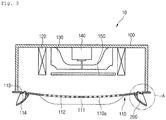
- Fig. 3 is a cross-sectional view taken along line I-I' of Fig. 1
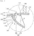
- Fig. 4 is an enlarged view illustrating a portion A of Fig. 3 .
- an air conditioner 10 includes a casing 100 in which a plurality of components for air-conditioning are built, a front panel 110 disposed on a front surface of the casing 100, and a wind-visor 200 disposed on a side of the front panel 110.
- the air conditioner 10 is buried in a ceiling.
- a direction from the ceiling toward an indoor space may be defined as a "front direction”
- a direction from the indoor space toward the ceiling may be defined as a "rear direction”.
- a heat exchanger 120 in which a refrigerant flows to heat-exchange with surrounding air, a blower fan 130 disposed on a side of the heat exchanger 120, a blower motor 140 for driving the blower fan 130, and a filter part for filtering foreign substances contained in air flowing into the casing 100 may be installed in the casing 100.
- the heat exchanger 120 may be disposed to surround the periphery of the blower fan 130.
- the heat exchanger 120 according to the current embodiment is not limited in position or shape.
- the filter part 150 may be disposed at one point of a flow path of air that forcibly flows by the blower fan 130.
- the filter part 150 may be disposed between the blower fan 130 and the front panel 110. That is, the filter part 150 may be disposed at a rear side of the front panel 110 to remove foreign substances contained in air that is introduced into the blower fan 130.
- the filter part 150 may be disposed on a side surface of the heat exchanger 120 or a side of a discharge part of the air conditioner 10.
- the filter part 150 according to the current embodiment is not limited to position or shape.
- the front panel includes a suction hole 111 for suctioning indoor air, a front grill 112 disposed on the suction hole 110 to prevent foreign substances having relatively large volume from being introduced, a discharge hole 113 that is opened in a side of the suction hole 110 to discharge air, a discharge louver 114 for selectively opening or closing the discharge hole, and a wind-visor 200 disposed on a side of the discharge hole 113.
- the suction hole 111 may be defined in the central portion 110a of the front panel 110.
- the suction hole 110 may be defined in the protruding central portion 110a of the front panel 110.
- the front grill 112 may be disposed on the suction hole 111 to filter foreign substances contained in air passing through the suction hole 111.
- the front grill 112 may include a plurality of ribs coupled to each other to form a lattice pattern.
- At least one discharge hole 113 may be defined in an edge of the front panel 110.
- the discharge hole 113 may be spaced apart outward from the suction hole 111.
- the discharge hole 113 may be provided in plurality along the edge of the front panel 110.
- the front grill 112 has a square shape
- four discharge holes 113 may be provided to correspond to four sides of the front grill 112.
- the discharge hole 113 may be defined in the protruding curved surface of the central portion 110a.
- the discharge hole 113 may be defined in a direction in which the discharge hole 113 is inclined outward toward a front side of the front panel 110, i.e., inclined outward with respect to the ground. Thus, air discharged from the discharge hole 113 may be uniformly spread to the surrounding without being concentrated into a front side of the air conditioner 10.
- the first edge 113 may be disposed toward the inside of the front panel 110, and the second edge 113b may be disposed toward the outside of the front panel 110.
- the discharge hole 113 may be defined by a space between the first edge 113a and the second edge 113b.
- the discharge louver 114 may be disposed in the discharge hole 113 to selectively open or close the discharge hole 113.
- the discharge louver 114 may be rotatably connected to a rotation shaft.
- the rotation shaft may extend in a direction perpendicular to a flow direction of the air discharged through the discharge hole 113 and be coupled to the front panel 110.
- An opened degree of the discharge hole 113 may be determined according to a rotating angle of the discharge louver 114.
- the discharge hole 113 may be closed.
- the discharge louver 114 is disposed in a direction perpendicular to the front panel 110 (a second position)
- the discharge hole 113 may be fully opened.
- the discharge hole 113 may increase in opened degree.
- the more the discharge hole 113 increases in opened degree the more air discharged through the discharge hole 113 increases in discharge amount.
- the more the discharge hole 113 decreases in opened degree the more the air decreases in discharge amount.
- a discharge direction of the air may be determined according to the rotating angle of the discharge louver 114.
- the wind-visor 200 may be detachably disposed on the front panel 110.
- the wind-visor 200 may prevent air discharged through the discharge hole 113 from being directly discharged to the user.
- the wind-visor 200 includes a portion that vertically overlaps with the discharge hole 113 and a portion that does not overlap with the discharge hole 113.
- the overlapping portion may be defined as a blocking portion 260, and the non-overlapping portion may be defined as an extension portion 270.
- a first virtual line 11 extending forward from the first edge 113a of the discharge hole 113 may meet a front portion or front surface of the wind-visor 200.
- a second virtual line 12 extending forward from the second edge 113b of the discharge hole 113 may meet the front portion or front surface of the wind-visor 200.
- the virtual line extending forward from each of both ends of the discharge louver 114 may meet the wind-visor 200.
- the first virtual line 11 may be a reference line for distinguishing a coupling part 210 and a guide part 250 of the wind-visor 200 from each other. That is, the coupling part 210 and the guide part 250 may be partitioned by the first virtual line 12.
- the second virtual line 12 may be a reference line for distinguishing the blocking portion 260 and the extension portion 270 of the guide part from each other. That is, the blocking portion 260 and the extension portion 270 may be partitioned by the second virtual line 12.
- the wind-visor 200 includes the coupling part 210 attached to the front panel 110 and the guide part 250 extending from the coupling part 210.
- the coupling part 210 and the guide part 250 may be integrated with each other.
- the coupling part 210 may be selectively coupled to the front panel 110, and the guide part 250 may extend from the coupling part 210 to guide the air discharged from the discharge hole 113 in a direction away from the suction hole 111.
- the coupling part 210 may be attached between the discharge hole 113 and the suction hole 111.
- the coupling part 210 may have one surface that is defined by extending forward from the first edge 113a of the discharge hole 113. That is, the one surface of the coupling part 210 and the first edge 113a may form a flat surface.
- both sides of the coupling part 210 may be rounded toward both sides of the discharge hole 113 when compared to a central portion of the coupling part 210. That is, the coupling part 210 may be gradually bent outward from the central portion thereof toward both sides of the discharge hole 113 to effectively discharge air toward both sides of the discharge hole 113.
- the coupling part 210 may have a shape that gradually decreases in cross-section downward from an upper portion thereof. That is to say, the portion (a first portion) of the coupling part 210 coupled to the front panel 110 may have a cross-section greater than that of a portion (a second portion) extending forward from the first portion. That is, the coupling part 210 may have a cross-section that gradually decreases from the front panel 110 toward the guide part 250.
- the portion of the coupling part 210 coupled to the front panel 110 may have a shape of which a central portion is bent forward to correspond to the shape of the front panel 110.
- a first coupling unit 220 to be coupled to the front panel 110 may be disposed on the coupling part 210.
- the first coupling unit 220 may include a first installation groove 222 that is recessed from one side of the coupling part 210 and a first magnet 224 disposed in the first installation groove 222.
- the one side of the coupling part 210 may be understood as a coupling surface to be coupled to the front panel 110.
- the first magnet 224 may be disposed in the first installation groove 222.
- the coupling part 210 may be manufactured in a state where the first magnet 224 is built in the coupling part 210. That is, the wind-visor 200 may be injection-molded in a form in which the first magnet 224 is inserted into the coupling part 210.
- the second installation groove 117 may be defined between the discharge hole 113 and the suction hole 111 with respect to the front panel 110.
- the second installation groove 117 may be recessed from one surface of the front panel 110, i.e., "a back surface” of the front panel 110. That is, the second installation groove 117 may be disposed so that the second installation groove 117 goes out of sight.
- the wind-visor 200 is coupled to a "front surface" of the front panel 110.
- the guide part 250 may guide the air discharged through the discharge hole 113 toward the outside of the front panel 110.
- the guide part 250 may include a blocking portion 260 that vertically overlaps with the discharge hole 113 and an extension portion 270 that extends from the blocking portion 260.
- the blocking portion 260 may be understood as a portion of the guide part 250 disposed between the first virtual line 11 and the second virtual line 12.
- both sides of the blocking portion 260 may be bent toward both sides of the discharge hole 113 when compared to a central portion of the blocking portion 260. That is, the blocking portion 260 may be gradually bent outward from the central portion thereof toward both sides of the discharge hole 113 to guide the air blocked by the blocking portion 260 to both sides of the discharge hole 113.
- the extension portion 270 may guide the air discharged from the discharge hole 113 in a direction that is far away from the air conditioner 10.
- the extension portion 270 may be defined as a portion of the guide part 250 that does not vertically overlap with the discharge hole 113.
- the front panel 110 may include a first panel part between the discharge hole 113 and the suction hole 111 and a second panel part disposed on a side opposite to the suction hole with respect to the discharge hole 113.
- the coupling part 210 may vertically overlap with the first panel part, and the blocking portion may vertically overlap with the discharge hole 113.
- the extension portion 270 may vertically overlap with the second panel part.
- Fig. 5 is a top view of a wind-visor according to an embodiment.
- a hollow 212 and a support rib 214 crossing the hollow 212 may be defined or disposed in the coupling part 210.
- the coupling part 210 may be reduced in weight due to the hollow 212. Also, the hollow 212 may be partitioned into a plurality of spaces by the support rib 214.
- At least one space of the plurality of spaces may form the first installation groove 222 in which the first magnet 224 is inserted.
- the first installation groove 222 may be defined in a position that is bilaterally symmetrical with respect to the central portion of the wind-visor 200.
- the coupling part 210 may be maintained in strength by the support rib 214.
- the support rib 214 may be understood as a structure that forms one wall of the first installation groove 222.
- it may prevent the conditioned air, i.e., the hot or warm air from being concentrated into a specific position with the indoor space to uniformly condition air in the indoor space.
- the manufacturing process of the wind-visor may be simplified to reduce manufacturing costs.
- the wind-visor may be lightweight to reduce a load applied to the air conditioner and prevent the safety accident due to the falling of the wind-visor from occurring.
- the wind-visor since the wind-visor is detachably provided according to the operation mode or indoor conditions, it may be unnecessary to form a separate hole in the outer surface of the air conditioner. Thus, the front panel of the air conditioner may not be deteriorated in durability.
- the air backflow phenomenon in which the air discharged from the discharge hole returns to the suction hole of the air conditioner may be prevented to improve energy efficiency in the air conditioner.
Landscapes
- Engineering & Computer Science (AREA)
- Chemical & Material Sciences (AREA)
- Combustion & Propulsion (AREA)
- Mechanical Engineering (AREA)
- General Engineering & Computer Science (AREA)
- Physics & Mathematics (AREA)
- Thermal Sciences (AREA)
- Air Filters, Heat-Exchange Apparatuses, And Housings Of Air-Conditioning Units (AREA)
- Air-Flow Control Members (AREA)
Claims (14)
- Climatiseur, comprenant :un corps principal comportant un ventilateur de soufflage (130) générant un flux d'air et un échangeur de chaleur (120) soumettant à échange de chaleur l'air soufflé par le ventilateur de soufflage ;un panneau avant (110) comprenant un orifice d'aspiration (111) par lequel l'air entrant dans le ventilateur de soufflage est aspiré et un orifice de refoulement (113) par lequel l'air soumis à échange de chaleur dans l'échangeur de chaleur est refoulé ;un écran coupe-vent (200) monté de manière amovible sur un côté de l'orifice de refoulement ; etun volet de refoulement (114) monté dans l'orifice de refoulement pour régler un degré d'ouverture de l'orifice de refoulement,où l'écran coupe-vent (200) est raccordé à un côté du volet de refoulement (114) pour guider l'évacuation de l'air par l'orifice de refoulement (113).
- Climatiseur selon la revendication 1, où l'écran coupe-vent (200) est disposé entre l'orifice de refoulement (113) et l'orifice d'aspiration (111).
- Climatiseur selon la revendication 1, où l'écran coupe-vent (200) est raccordé de manière amovible au panneau avant (110).
- Climatiseur selon la revendication 1, comprenant en outre :un premier aimant (224) monté sur l'écran coupe-vent (200) ; etun deuxième aimant (118) monté sur le panneau avant (110),le deuxième aimant étant couplé sélectivement au premier aimant.
- Climatiseur selon la revendication 4, comprenant en outre une deuxième rainure de montage (117) définie dans le panneau avant (110) de manière à y inclure le deuxième aimant (118), ladite deuxième rainure de montage étant définie entre l'orifice de refoulement (113) et l'orifice d'aspiration (111).
- Climatiseur selon la revendication 5, où l'écran coupe-vent (200) est raccordé à une surface avant du panneau avant (110), et la deuxième rainure de montage (117) est ménagée dans une surface arrière du panneau avant (110).
- Climatiseur selon la revendication 1, où l'écran coupe-vent (200) comprend :une partie de liaison (210) raccordée sélectivement à la face avant du panneau avant (110); etune partie de guidage (250) s'étendant depuis la partie de liaison pour guider l'air évacué par l'orifice de refoulement (113) dans une direction opposée à l'orifice d'aspiration (111).
- Climatiseur selon la revendication 7, où la partie de guidage (250) comprend :une partie de blocage (260) en chevauchement avec l'orifice de refoulement (113) sur le côté avant de l'orifice de refoulement ; etune partie d'extension (270) s'étendant depuis la partie de blocage sans chevaucher l'orifice de refoulement (113) sur le côté avant de l'orifice de refoulement.
- Climatiseur selon la revendication 8, où le panneau avant (110) comprend un premier bord et un deuxième bord définissant l'orifice de refoulement (113), et où une première ligne virtuelle (11) s'étendant vers l'avant depuis le premier bord et une deuxième ligne virtuelle (12) s'étendant vers l'avant depuis le deuxième bord sont incidentes à une partie avant ou à une surface avant de l'écran coupe-vent (200).
- Climatiseur selon la revendication 9, où la deuxième ligne virtuelle (12) définit une ligne de référence pour distinguer l'une de l'autre la partie de liaison (210) et la partie de guidage (250) de l'écran coupe-vent (200).
- Climatiseur selon la revendication 7, où la partie de liaison (210) comprend :un premier aimant (224) couplé sélectivement à un deuxième aimant (118) du panneau avant (110) ; etune première rainure de montage (222) où est monté le premier aimant (224).
- Climatiseur selon la revendication 11, où la partie de liaison (210) comprend :une pluralité de cavités (212); etau moins une entretoise de support (214) pour la séparation de la pluralité de cavités.
- Climatiseur selon la revendication 12, où au moins une cavité (212) de la pluralité de cavités comprend la première rainure de montage (222).
- Climatiseur selon la revendication 7, où la partie de liaison (210) présente une grandeur de section transversale diminuant progressivement en largeur du panneau avant (110) à la partie de guidage (250).
Applications Claiming Priority (1)
| Application Number | Priority Date | Filing Date | Title |
|---|---|---|---|
| KR1020130077017A KR102053223B1 (ko) | 2013-07-02 | 2013-07-02 | 바람 가리개 및 이를 포함한 공기 조화기 |
Publications (2)
| Publication Number | Publication Date |
|---|---|
| EP2821716A1 EP2821716A1 (fr) | 2015-01-07 |
| EP2821716B1 true EP2821716B1 (fr) | 2019-12-18 |
Family
ID=51162489
Family Applications (1)
| Application Number | Title | Priority Date | Filing Date |
|---|---|---|---|
| EP14175399.6A Active EP2821716B1 (fr) | 2013-07-02 | 2014-07-02 | climatiseur avec un écran pour détourner l'air |
Country Status (3)
| Country | Link |
|---|---|
| US (1) | US20150007967A1 (fr) |
| EP (1) | EP2821716B1 (fr) |
| KR (1) | KR102053223B1 (fr) |
Families Citing this family (32)
| Publication number | Priority date | Publication date | Assignee | Title |
|---|---|---|---|---|
| JP4952775B2 (ja) * | 2009-11-05 | 2012-06-13 | ダイキン工業株式会社 | 空気調和装置の室内機 |
| KR102278182B1 (ko) * | 2013-10-29 | 2021-07-15 | 엘지전자 주식회사 | 공기조화기 |
| JP1541102S (fr) * | 2014-06-06 | 2017-12-18 | ||
| JP1523384S (fr) * | 2014-07-14 | 2015-05-18 | ||
| USD759222S1 (en) * | 2014-09-23 | 2016-06-14 | Daikin Industries Ltd. | Air conditioner |
| USD759223S1 (en) * | 2014-09-23 | 2016-06-14 | Daikin Industries Ltd. | Air conditioner |
| JP1535862S (fr) * | 2015-01-29 | 2015-10-26 | ||
| JP1536295S (fr) * | 2015-01-29 | 2015-10-26 | ||
| JP1536294S (fr) * | 2015-01-29 | 2015-10-26 | ||
| JP1536293S (fr) * | 2015-01-29 | 2015-10-26 | ||
| JP1535861S (fr) * | 2015-01-29 | 2015-10-26 | ||
| JP1535863S (fr) * | 2015-01-29 | 2015-10-26 | ||
| US20160229257A1 (en) * | 2015-02-10 | 2016-08-11 | Ford Global Technologies, Llc | Vehicle and vehicle cabin air extraction system |
| CN104697058B (zh) * | 2015-02-13 | 2017-06-27 | 广东美的制冷设备有限公司 | 空调室内机及其控制方法 |
| WO2016133261A1 (fr) * | 2015-02-18 | 2016-08-25 | 삼성전자주식회사 | Climatiseur |
| KR102067449B1 (ko) * | 2015-10-23 | 2020-01-17 | 삼성전자주식회사 | 공기 조화기 및 그 제어 방법 |
| KR101881907B1 (ko) | 2015-10-23 | 2018-07-27 | 삼성전자주식회사 | 공기 조화기 및 그 제어 방법 |
| CN106642311B (zh) * | 2016-09-19 | 2022-05-27 | 珠海格力电器股份有限公司 | 空调器及其控制方法 |
| KR102391356B1 (ko) * | 2017-04-28 | 2022-04-28 | 삼성전자주식회사 | 공기조화기 |
| CN107314453B (zh) * | 2017-08-21 | 2024-04-02 | 广东美的制冷设备有限公司 | 壁挂式室内机及空调器 |
| KR102249321B1 (ko) * | 2017-09-05 | 2021-05-07 | 삼성전자주식회사 | 공기조화기 |
| KR102392956B1 (ko) * | 2017-09-06 | 2022-04-29 | 엘지전자 주식회사 | 공기조화기 |
| USD862670S1 (en) * | 2018-01-08 | 2019-10-08 | Samsung Electronics Co., Ltd. | Ceiling-mounted air conditioner |
| USD860423S1 (en) * | 2018-01-08 | 2019-09-17 | Samsung Electronics Co., Ltd. | Ceiling-mounted air conditioner |
| JP6641606B2 (ja) * | 2018-03-30 | 2020-02-05 | 株式会社富士通ゼネラル | 天井埋込型空気調和機 |
| JP7070085B2 (ja) * | 2018-05-21 | 2022-05-18 | 株式会社富士通ゼネラル | 天井埋込型空気調和機 |
| CN111023299A (zh) * | 2019-12-27 | 2020-04-17 | 海信(山东)空调有限公司 | 空调器制冷防直吹的控制方法、装置、存储介质及空调器 |
| USD1033622S1 (en) * | 2021-09-08 | 2024-07-02 | Lg Electronics Inc. | Air ventilation system |
| USD1034935S1 (en) * | 2021-09-08 | 2024-07-09 | Lg Electronics Inc. | Air ventilation system |
| USD1033621S1 (en) * | 2021-09-08 | 2024-07-02 | Lg Electronics Inc. | Air ventilation system |
| CN114396650A (zh) * | 2022-01-10 | 2022-04-26 | 珠海格力节能环保制冷技术研究中心有限公司 | 一种分布式送风风管机和分布式送风装置 |
| KR20230118466A (ko) * | 2022-02-04 | 2023-08-11 | 삼성전자주식회사 | 천장형 공기조화기 |
Citations (1)
| Publication number | Priority date | Publication date | Assignee | Title |
|---|---|---|---|---|
| KR20120111822A (ko) * | 2011-04-02 | 2012-10-11 | 정인근 | 에어컨용 바람 안내장치 |
Family Cites Families (28)
| Publication number | Priority date | Publication date | Assignee | Title |
|---|---|---|---|---|
| US2363839A (en) * | 1941-02-05 | 1944-11-28 | Demuth Charles | Unit type air conditioning register |
| US3752055A (en) * | 1972-01-07 | 1973-08-14 | American Air Filter Co | Grille arrangement for clean rooms |
| US4702087A (en) * | 1985-03-29 | 1987-10-27 | Mitsubishi Denki Kabushiki Kaisha | Ceiling suspended air conditioner |
| JP3240854B2 (ja) * | 1994-09-26 | 2001-12-25 | 三菱電機株式会社 | 空気調和機の吹出口 |
| US6598413B2 (en) * | 1999-01-25 | 2003-07-29 | Mitsubishi Denki Kabushiki Kaisha | Ceiling embedded-type air conditioner |
| JP3408983B2 (ja) * | 1999-01-25 | 2003-05-19 | 三菱電機株式会社 | 天井埋込型空気調和機 |
| KR100628205B1 (ko) * | 2003-05-28 | 2006-09-26 | 엘지전자 주식회사 | 환기겸용 공조시스템 및 그 제어방법 |
| US7258607B1 (en) * | 2004-03-12 | 2007-08-21 | Machiorlette Steven C | Return air grille assembly |
| KR20060099004A (ko) * | 2005-03-10 | 2006-09-19 | 엘지전자 주식회사 | 공기 조화기 |
| CA2510905A1 (fr) * | 2005-06-23 | 2006-12-23 | Sherry Romanuik | Systeme d'accrochage de grilles a persiennes magnetiques |
| KR100782197B1 (ko) * | 2006-08-03 | 2007-12-04 | 엘지전자 주식회사 | 공기 조화기 |
| KR100782195B1 (ko) * | 2006-08-10 | 2007-12-04 | 엘지전자 주식회사 | 공기 조화기 |
| US7651390B1 (en) * | 2007-03-12 | 2010-01-26 | Profeta Jeffery L | Ceiling vent air diverter |
| JP5194023B2 (ja) * | 2007-10-25 | 2013-05-08 | 東芝キヤリア株式会社 | 天井埋込型の空気調和機 |
| US8419515B1 (en) * | 2008-01-17 | 2013-04-16 | Kevin Dillon | Magnetic register vent cover and associated method |
| US20090264062A1 (en) * | 2008-04-16 | 2009-10-22 | Nuclimate Air Quality Systems, Inc. | Ventilation system |
| JP4969523B2 (ja) * | 2008-07-02 | 2012-07-04 | 三菱電機株式会社 | 空気調和機 |
| KR200450709Y1 (ko) * | 2008-08-19 | 2010-10-25 | 주식회사 힘펠 | 환풍기 그릴 및 그릴커버의 착탈 구조 |
| JP2010084996A (ja) * | 2008-09-30 | 2010-04-15 | Hitachi Appliances Inc | 空気調和機 |
| US8292708B2 (en) * | 2009-01-26 | 2012-10-23 | Elima-Draft Incorporated | Magnetic register cover |
| JP4952775B2 (ja) * | 2009-11-05 | 2012-06-13 | ダイキン工業株式会社 | 空気調和装置の室内機 |
| JP4924697B2 (ja) * | 2009-11-05 | 2012-04-25 | ダイキン工業株式会社 | 空気調和装置の室内機 |
| JP5384443B2 (ja) | 2010-07-28 | 2014-01-08 | 日東電工株式会社 | フリップチップ型半導体裏面用フィルム、ダイシングテープ一体型半導体裏面用フィルム、半導体装置の製造方法、及び、フリップチップ型半導体装置 |
| KR20120001065U (ko) * | 2010-08-05 | 2012-02-15 | 고영신 | 천장형 에어컨 바람 가이드 |
| JP5247784B2 (ja) * | 2010-10-04 | 2013-07-24 | 三菱電機株式会社 | 空気調和機 |
| JP5250011B2 (ja) * | 2010-10-26 | 2013-07-31 | 三菱電機株式会社 | 空気調和機 |
| KR102076684B1 (ko) * | 2013-02-21 | 2020-02-12 | 엘지전자 주식회사 | 터보팬 및 이를 사용한 천정형 공기조화기 |
| USD754837S1 (en) * | 2013-12-19 | 2016-04-26 | Lg Electronics Inc. | Air deflector for ceiling air conditioner |
-
2013
- 2013-07-02 KR KR1020130077017A patent/KR102053223B1/ko active Active
-
2014
- 2014-07-02 US US14/321,992 patent/US20150007967A1/en not_active Abandoned
- 2014-07-02 EP EP14175399.6A patent/EP2821716B1/fr active Active
Patent Citations (1)
| Publication number | Priority date | Publication date | Assignee | Title |
|---|---|---|---|---|
| KR20120111822A (ko) * | 2011-04-02 | 2012-10-11 | 정인근 | 에어컨용 바람 안내장치 |
Also Published As
| Publication number | Publication date |
|---|---|
| EP2821716A1 (fr) | 2015-01-07 |
| KR102053223B1 (ko) | 2020-01-07 |
| US20150007967A1 (en) | 2015-01-08 |
| KR20150004471A (ko) | 2015-01-13 |
Similar Documents
| Publication | Publication Date | Title |
|---|---|---|
| EP2821716B1 (fr) | climatiseur avec un écran pour détourner l'air | |
| EP2719959B1 (fr) | Climatiseur | |
| EP2719969B1 (fr) | Climatiseur | |
| EP2997312B1 (fr) | Unité intérieure de climatiseur | |
| EP2860462B1 (fr) | Unité d'intérieur pour climatiseur de type cartouche | |
| EP3998430B1 (fr) | Unité intérieure d'appareil de conditionnement d'air et unité d'aube appliquée à celle-ci | |
| EP3514459B1 (fr) | Climatiseur | |
| EP3009752A1 (fr) | Climatiseur | |
| EP4596980A2 (fr) | Climatiseur | |
| KR102425866B1 (ko) | 공기조화기의 제어방법 | |
| KR20190026325A (ko) | 공기조화기 | |
| CN110662923A (zh) | 吊顶式空气调节设备用空气引导件及具备其的吊顶式空气调节设备 | |
| CN106403230B (zh) | 导风板及具有其的壁挂式空调室内机 | |
| EP2792886A2 (fr) | Turboventilateur | |
| EP4273459B1 (fr) | Climatiseur | |
| KR102343464B1 (ko) | 천장형 에어컨 실내기 | |
| CN212378103U (zh) | 一种空调出风结构及空调 | |
| KR100714591B1 (ko) | 액자형 공기조화기용 실내기 | |
| JP5803974B2 (ja) | 化粧パネル及びそれを備えた空気調和機の室内ユニット | |
| KR200459768Y1 (ko) | 천정형 냉난방기의 공기순환 장치 | |
| KR101454758B1 (ko) | 차량 공조장치용 송풍팬 | |
| EP4269884B1 (fr) | Climatiseur | |
| CN222335487U (zh) | 一种浴霸的进风结构 | |
| KR20150085218A (ko) | 공기조화기 | |
| KR200467785Y1 (ko) | 공기조화기 |
Legal Events
| Date | Code | Title | Description |
|---|---|---|---|
| PUAI | Public reference made under article 153(3) epc to a published international application that has entered the european phase |
Free format text: ORIGINAL CODE: 0009012 |
|
| 17P | Request for examination filed |
Effective date: 20140731 |
|
| AK | Designated contracting states |
Kind code of ref document: A1 Designated state(s): AL AT BE BG CH CY CZ DE DK EE ES FI FR GB GR HR HU IE IS IT LI LT LU LV MC MK MT NL NO PL PT RO RS SE SI SK SM TR |
|
| AX | Request for extension of the european patent |
Extension state: BA ME |
|
| RBV | Designated contracting states (corrected) |
Designated state(s): AL AT BE BG CH CY CZ DE DK EE ES FI FR GB GR HR HU IE IS IT LI LT LU LV MC MK MT NL NO PL PT RO RS SE SI SK SM TR |
|
| GRAP | Despatch of communication of intention to grant a patent |
Free format text: ORIGINAL CODE: EPIDOSNIGR1 |
|
| STAA | Information on the status of an ep patent application or granted ep patent |
Free format text: STATUS: GRANT OF PATENT IS INTENDED |
|
| RIC1 | Information provided on ipc code assigned before grant |
Ipc: F24F 1/00 20190101AFI20190607BHEP Ipc: F24F 1/0047 20190101ALI20190607BHEP Ipc: F24F 1/0014 20190101ALI20190607BHEP Ipc: F24F 13/06 20060101ALI20190607BHEP Ipc: F24F 1/0011 20190101ALI20190607BHEP Ipc: F24F 13/08 20060101ALI20190607BHEP |
|
| INTG | Intention to grant announced |
Effective date: 20190705 |
|
| GRAS | Grant fee paid |
Free format text: ORIGINAL CODE: EPIDOSNIGR3 |
|
| GRAA | (expected) grant |
Free format text: ORIGINAL CODE: 0009210 |
|
| STAA | Information on the status of an ep patent application or granted ep patent |
Free format text: STATUS: THE PATENT HAS BEEN GRANTED |
|
| AK | Designated contracting states |
Kind code of ref document: B1 Designated state(s): AL AT BE BG CH CY CZ DE DK EE ES FI FR GB GR HR HU IE IS IT LI LT LU LV MC MK MT NL NO PL PT RO RS SE SI SK SM TR |
|
| REG | Reference to a national code |
Ref country code: CH Ref legal event code: EP |
|
| REG | Reference to a national code |
Ref country code: DE Ref legal event code: R096 Ref document number: 602014058483 Country of ref document: DE |
|
| REG | Reference to a national code |
Ref country code: IE Ref legal event code: FG4D |
|
| REG | Reference to a national code |
Ref country code: AT Ref legal event code: REF Ref document number: 1215037 Country of ref document: AT Kind code of ref document: T Effective date: 20200115 |
|
| REG | Reference to a national code |
Ref country code: NL Ref legal event code: MP Effective date: 20191218 |
|
| PG25 | Lapsed in a contracting state [announced via postgrant information from national office to epo] |
Ref country code: LT Free format text: LAPSE BECAUSE OF FAILURE TO SUBMIT A TRANSLATION OF THE DESCRIPTION OR TO PAY THE FEE WITHIN THE PRESCRIBED TIME-LIMIT Effective date: 20191218 Ref country code: GR Free format text: LAPSE BECAUSE OF FAILURE TO SUBMIT A TRANSLATION OF THE DESCRIPTION OR TO PAY THE FEE WITHIN THE PRESCRIBED TIME-LIMIT Effective date: 20200319 Ref country code: NO Free format text: LAPSE BECAUSE OF FAILURE TO SUBMIT A TRANSLATION OF THE DESCRIPTION OR TO PAY THE FEE WITHIN THE PRESCRIBED TIME-LIMIT Effective date: 20200318 Ref country code: BG Free format text: LAPSE BECAUSE OF FAILURE TO SUBMIT A TRANSLATION OF THE DESCRIPTION OR TO PAY THE FEE WITHIN THE PRESCRIBED TIME-LIMIT Effective date: 20200318 Ref country code: FI Free format text: LAPSE BECAUSE OF FAILURE TO SUBMIT A TRANSLATION OF THE DESCRIPTION OR TO PAY THE FEE WITHIN THE PRESCRIBED TIME-LIMIT Effective date: 20191218 Ref country code: LV Free format text: LAPSE BECAUSE OF FAILURE TO SUBMIT A TRANSLATION OF THE DESCRIPTION OR TO PAY THE FEE WITHIN THE PRESCRIBED TIME-LIMIT Effective date: 20191218 Ref country code: SE Free format text: LAPSE BECAUSE OF FAILURE TO SUBMIT A TRANSLATION OF THE DESCRIPTION OR TO PAY THE FEE WITHIN THE PRESCRIBED TIME-LIMIT Effective date: 20191218 |
|
| REG | Reference to a national code |
Ref country code: LT Ref legal event code: MG4D |
|
| PG25 | Lapsed in a contracting state [announced via postgrant information from national office to epo] |
Ref country code: RS Free format text: LAPSE BECAUSE OF FAILURE TO SUBMIT A TRANSLATION OF THE DESCRIPTION OR TO PAY THE FEE WITHIN THE PRESCRIBED TIME-LIMIT Effective date: 20191218 Ref country code: HR Free format text: LAPSE BECAUSE OF FAILURE TO SUBMIT A TRANSLATION OF THE DESCRIPTION OR TO PAY THE FEE WITHIN THE PRESCRIBED TIME-LIMIT Effective date: 20191218 |
|
| PG25 | Lapsed in a contracting state [announced via postgrant information from national office to epo] |
Ref country code: AL Free format text: LAPSE BECAUSE OF FAILURE TO SUBMIT A TRANSLATION OF THE DESCRIPTION OR TO PAY THE FEE WITHIN THE PRESCRIBED TIME-LIMIT Effective date: 20191218 |
|
| PG25 | Lapsed in a contracting state [announced via postgrant information from national office to epo] |
Ref country code: NL Free format text: LAPSE BECAUSE OF FAILURE TO SUBMIT A TRANSLATION OF THE DESCRIPTION OR TO PAY THE FEE WITHIN THE PRESCRIBED TIME-LIMIT Effective date: 20191218 Ref country code: RO Free format text: LAPSE BECAUSE OF FAILURE TO SUBMIT A TRANSLATION OF THE DESCRIPTION OR TO PAY THE FEE WITHIN THE PRESCRIBED TIME-LIMIT Effective date: 20191218 Ref country code: PT Free format text: LAPSE BECAUSE OF FAILURE TO SUBMIT A TRANSLATION OF THE DESCRIPTION OR TO PAY THE FEE WITHIN THE PRESCRIBED TIME-LIMIT Effective date: 20200513 Ref country code: EE Free format text: LAPSE BECAUSE OF FAILURE TO SUBMIT A TRANSLATION OF THE DESCRIPTION OR TO PAY THE FEE WITHIN THE PRESCRIBED TIME-LIMIT Effective date: 20191218 Ref country code: CZ Free format text: LAPSE BECAUSE OF FAILURE TO SUBMIT A TRANSLATION OF THE DESCRIPTION OR TO PAY THE FEE WITHIN THE PRESCRIBED TIME-LIMIT Effective date: 20191218 |
|
| PG25 | Lapsed in a contracting state [announced via postgrant information from national office to epo] |
Ref country code: SK Free format text: LAPSE BECAUSE OF FAILURE TO SUBMIT A TRANSLATION OF THE DESCRIPTION OR TO PAY THE FEE WITHIN THE PRESCRIBED TIME-LIMIT Effective date: 20191218 Ref country code: SM Free format text: LAPSE BECAUSE OF FAILURE TO SUBMIT A TRANSLATION OF THE DESCRIPTION OR TO PAY THE FEE WITHIN THE PRESCRIBED TIME-LIMIT Effective date: 20191218 Ref country code: IS Free format text: LAPSE BECAUSE OF FAILURE TO SUBMIT A TRANSLATION OF THE DESCRIPTION OR TO PAY THE FEE WITHIN THE PRESCRIBED TIME-LIMIT Effective date: 20200418 |
|
| REG | Reference to a national code |
Ref country code: DE Ref legal event code: R097 Ref document number: 602014058483 Country of ref document: DE |
|
| REG | Reference to a national code |
Ref country code: AT Ref legal event code: MK05 Ref document number: 1215037 Country of ref document: AT Kind code of ref document: T Effective date: 20191218 |
|
| PLBE | No opposition filed within time limit |
Free format text: ORIGINAL CODE: 0009261 |
|
| STAA | Information on the status of an ep patent application or granted ep patent |
Free format text: STATUS: NO OPPOSITION FILED WITHIN TIME LIMIT |
|
| PG25 | Lapsed in a contracting state [announced via postgrant information from national office to epo] |
Ref country code: DK Free format text: LAPSE BECAUSE OF FAILURE TO SUBMIT A TRANSLATION OF THE DESCRIPTION OR TO PAY THE FEE WITHIN THE PRESCRIBED TIME-LIMIT Effective date: 20191218 Ref country code: ES Free format text: LAPSE BECAUSE OF FAILURE TO SUBMIT A TRANSLATION OF THE DESCRIPTION OR TO PAY THE FEE WITHIN THE PRESCRIBED TIME-LIMIT Effective date: 20191218 |
|
| 26N | No opposition filed |
Effective date: 20200921 |
|
| PG25 | Lapsed in a contracting state [announced via postgrant information from national office to epo] |
Ref country code: SI Free format text: LAPSE BECAUSE OF FAILURE TO SUBMIT A TRANSLATION OF THE DESCRIPTION OR TO PAY THE FEE WITHIN THE PRESCRIBED TIME-LIMIT Effective date: 20191218 Ref country code: AT Free format text: LAPSE BECAUSE OF FAILURE TO SUBMIT A TRANSLATION OF THE DESCRIPTION OR TO PAY THE FEE WITHIN THE PRESCRIBED TIME-LIMIT Effective date: 20191218 |
|
| PG25 | Lapsed in a contracting state [announced via postgrant information from national office to epo] |
Ref country code: IT Free format text: LAPSE BECAUSE OF FAILURE TO SUBMIT A TRANSLATION OF THE DESCRIPTION OR TO PAY THE FEE WITHIN THE PRESCRIBED TIME-LIMIT Effective date: 20191218 |
|
| PG25 | Lapsed in a contracting state [announced via postgrant information from national office to epo] |
Ref country code: MC Free format text: LAPSE BECAUSE OF FAILURE TO SUBMIT A TRANSLATION OF THE DESCRIPTION OR TO PAY THE FEE WITHIN THE PRESCRIBED TIME-LIMIT Effective date: 20191218 Ref country code: PL Free format text: LAPSE BECAUSE OF FAILURE TO SUBMIT A TRANSLATION OF THE DESCRIPTION OR TO PAY THE FEE WITHIN THE PRESCRIBED TIME-LIMIT Effective date: 20191218 |
|
| REG | Reference to a national code |
Ref country code: CH Ref legal event code: PL |
|
| GBPC | Gb: european patent ceased through non-payment of renewal fee |
Effective date: 20200702 |
|
| REG | Reference to a national code |
Ref country code: BE Ref legal event code: MM Effective date: 20200731 |
|
| PG25 | Lapsed in a contracting state [announced via postgrant information from national office to epo] |
Ref country code: FR Free format text: LAPSE BECAUSE OF NON-PAYMENT OF DUE FEES Effective date: 20200731 Ref country code: LU Free format text: LAPSE BECAUSE OF NON-PAYMENT OF DUE FEES Effective date: 20200702 Ref country code: IE Free format text: LAPSE BECAUSE OF NON-PAYMENT OF DUE FEES Effective date: 20200702 Ref country code: LI Free format text: LAPSE BECAUSE OF NON-PAYMENT OF DUE FEES Effective date: 20200731 Ref country code: GB Free format text: LAPSE BECAUSE OF NON-PAYMENT OF DUE FEES Effective date: 20200702 Ref country code: CH Free format text: LAPSE BECAUSE OF NON-PAYMENT OF DUE FEES Effective date: 20200731 |
|
| PG25 | Lapsed in a contracting state [announced via postgrant information from national office to epo] |
Ref country code: BE Free format text: LAPSE BECAUSE OF NON-PAYMENT OF DUE FEES Effective date: 20200731 |
|
| PG25 | Lapsed in a contracting state [announced via postgrant information from national office to epo] |
Ref country code: TR Free format text: LAPSE BECAUSE OF FAILURE TO SUBMIT A TRANSLATION OF THE DESCRIPTION OR TO PAY THE FEE WITHIN THE PRESCRIBED TIME-LIMIT Effective date: 20191218 Ref country code: MT Free format text: LAPSE BECAUSE OF FAILURE TO SUBMIT A TRANSLATION OF THE DESCRIPTION OR TO PAY THE FEE WITHIN THE PRESCRIBED TIME-LIMIT Effective date: 20191218 Ref country code: CY Free format text: LAPSE BECAUSE OF FAILURE TO SUBMIT A TRANSLATION OF THE DESCRIPTION OR TO PAY THE FEE WITHIN THE PRESCRIBED TIME-LIMIT Effective date: 20191218 |
|
| PG25 | Lapsed in a contracting state [announced via postgrant information from national office to epo] |
Ref country code: MK Free format text: LAPSE BECAUSE OF FAILURE TO SUBMIT A TRANSLATION OF THE DESCRIPTION OR TO PAY THE FEE WITHIN THE PRESCRIBED TIME-LIMIT Effective date: 20191218 |
|
| PGFP | Annual fee paid to national office [announced via postgrant information from national office to epo] |
Ref country code: DE Payment date: 20220603 Year of fee payment: 9 |
|
| REG | Reference to a national code |
Ref country code: DE Ref legal event code: R119 Ref document number: 602014058483 Country of ref document: DE |
|
| PG25 | Lapsed in a contracting state [announced via postgrant information from national office to epo] |
Ref country code: DE Free format text: LAPSE BECAUSE OF NON-PAYMENT OF DUE FEES Effective date: 20240201 |