EP2821858B1 - Bilderzeugungsvorrichtung - Google Patents
Bilderzeugungsvorrichtung Download PDFInfo
- Publication number
- EP2821858B1 EP2821858B1 EP14165635.5A EP14165635A EP2821858B1 EP 2821858 B1 EP2821858 B1 EP 2821858B1 EP 14165635 A EP14165635 A EP 14165635A EP 2821858 B1 EP2821858 B1 EP 2821858B1
- Authority
- EP
- European Patent Office
- Prior art keywords
- direct current
- transfer
- current component
- bias
- power supply
- Prior art date
- Legal status (The legal status is an assumption and is not a legal conclusion. Google has not performed a legal analysis and makes no representation as to the accuracy of the status listed.)
- Active
Links
Images




Classifications
-
- G—PHYSICS
- G03—PHOTOGRAPHY; CINEMATOGRAPHY; ANALOGOUS TECHNIQUES USING WAVES OTHER THAN OPTICAL WAVES; ELECTROGRAPHY; HOLOGRAPHY
- G03G—ELECTROGRAPHY; ELECTROPHOTOGRAPHY; MAGNETOGRAPHY
- G03G15/00—Apparatus for electrographic processes using a charge pattern
- G03G15/14—Apparatus for electrographic processes using a charge pattern for transferring a pattern to a second base
- G03G15/16—Apparatus for electrographic processes using a charge pattern for transferring a pattern to a second base of a toner pattern, e.g. a powder pattern, e.g. magnetic transfer
- G03G15/1665—Apparatus for electrographic processes using a charge pattern for transferring a pattern to a second base of a toner pattern, e.g. a powder pattern, e.g. magnetic transfer by introducing the second base in the nip formed by the recording member and at least one transfer member, e.g. in combination with bias or heat
- G03G15/167—Apparatus for electrographic processes using a charge pattern for transferring a pattern to a second base of a toner pattern, e.g. a powder pattern, e.g. magnetic transfer by introducing the second base in the nip formed by the recording member and at least one transfer member, e.g. in combination with bias or heat at least one of the recording member or the transfer member being rotatable during the transfer
- G03G15/1675—Apparatus for electrographic processes using a charge pattern for transferring a pattern to a second base of a toner pattern, e.g. a powder pattern, e.g. magnetic transfer by introducing the second base in the nip formed by the recording member and at least one transfer member, e.g. in combination with bias or heat at least one of the recording member or the transfer member being rotatable during the transfer with means for controlling the bias applied in the transfer nip
-
- G—PHYSICS
- G03—PHOTOGRAPHY; CINEMATOGRAPHY; ANALOGOUS TECHNIQUES USING WAVES OTHER THAN OPTICAL WAVES; ELECTROGRAPHY; HOLOGRAPHY
- G03G—ELECTROGRAPHY; ELECTROPHOTOGRAPHY; MAGNETOGRAPHY
- G03G15/00—Apparatus for electrographic processes using a charge pattern
- G03G15/14—Apparatus for electrographic processes using a charge pattern for transferring a pattern to a second base
- G03G15/16—Apparatus for electrographic processes using a charge pattern for transferring a pattern to a second base of a toner pattern, e.g. a powder pattern, e.g. magnetic transfer
- G03G15/1605—Apparatus for electrographic processes using a charge pattern for transferring a pattern to a second base of a toner pattern, e.g. a powder pattern, e.g. magnetic transfer using at least one intermediate support
Definitions
- the toner image on the intermediate transfer belt is secondarily transferred onto the recording sheet that has been fed into the secondary transfer nip at the time of synchronization with the toner images on the intermediate transfer belt through the action of the secondary transfer electric field or the nip pressure.
- the capacitor circuit in the board of the AC power supply requires a longer time for output response of the direct current component of the transfer bias than the example in which the DC voltage is output by using the DC power supply only. This often requires a longer time for rising-up of the bias until the bias reaches the target voltage value required for transferring images. As a result, the required transfer bias for transferring images at the leading end of the image cannot be ensured, which leads to insufficient transfer image density at the leading end of the image and thus causes poor transfer.
- the transfer bias is applied under the constant current control. This stabilizes the transfer electric field if the electric resistance of the intermediate transfer belt and/or the secondary transfer roller varies depending on the environmental conditions such as the temperature and the humidity, thereby achieving stable transferability.
- the printer includes four image forming units 1Y, 1M, 1C, and 1K for forming toner images of yellow, magenta, cyan, and black (hereinafter, referred to as Y, M, C, and K, respectively) colors, a transfer unit 30 serving as a transfer device, an optical writing unit 80, a fixing device 90, a paper cassette 100, a pair of registration rollers 101, and a control unit 60.
- the repulsive roller 33 includes a metal core and a conductive NBR rubber layer provided on the surface of the metal core.
- the secondary transfer roller 36 also includes a metal core and a conductive NBR rubber layer provided on the surface of the metal core.
- the secondary transfer bias is applied to the repulsive roller 33 and the secondary transfer roller 36 is grounded. If the polarity of the secondary transfer bias is the same negative polarity as the polarity of toner, the toner of negative polarity can be electrostatically forced from the side of the repulsive roller 33 to the side of the secondary transfer roller 36 in the secondary transfer nip N. This moves the toner on the intermediate transfer belt 31 onto the recording sheet P.
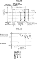
- the output at the time of risinging-up of the direct current component in the transfer bias is determined to be larger than the output at the time of transferring the image section (the output at the time of transferring the image section onto the recording material). This reduces the rise time of the direct current component (i.e., the direct current component quickly rises up to the value required for the image transfer), thereby preventing the insufficient density at the leading end of the image (the leading end of the sheet).
- the inventor(s) generates a solid image in blue by superimposing a solid image in magenta and a solid image in cyan to determine whether sufficient image density can be acquired at the leading end of the recording sheet.
- the direct current component rises up in two stages because in the first stage, the direct current component preferably rises up as quickly as possible by using a considerably large output target value (the control signals), and if so large output target value is maintained after the sheet enters the transfer nip, an electric discharge occurs.
- the direct current component rises up in two stages, (the output target value in the second stage ⁇ the output target value in the first stage), thereby achieving a quick rising-up and preventing an electric discharge.
- the output target value of the direct current component (the target value of the voltage or the target value of the current) when the direct current component in the transfer bias rises up is larger than the output target value (the target value of the voltage or the target value of the current) at the time of transferring the image section (when images are transferred onto a recording material), resulting in the direct current component quickly rising up.
- This achieves acquiring high-quality images while providing sufficient image density on both the recessed portions and the protruding portions on the surface of a recording sheet, without decreasing image density at the leading end of the recording sheet.
- the output target value of the bias for transfer therefore needs to be adjusted in such a small range from 12.8 to 20%. This often causes errors on the duty ratio output as the output target value of the bias for transfer. Alternatively, this requires such a large capacity of the storing area in the apparatus for storing values with many digits for setting the output target value.
- the image forming apparatus may have another configuration, such as the order of the image forming units in the tandem color printer.
- the present invention may also be applied to a full-color printer including three color toners or a multi-color printer including two color toners in addition to a four-color printer.
- the image forming apparatus is not limited to a printer and may be a copying machine, a facsimile, or a multifunction peripheral including a plurality of functions.
- the control unit 300 controls the secondary transfer bias power supply 200.
- the toner By applying the superimposed transfer bias including the direct current and setting the offset voltage Voff (applied time-averaged value) to the same polarity as the toner (negative in the present embodiment), the toner is reciprocally moved and is relatively moved from the intermediate transfer belt side to the recording sheet P. Thus, the toner is transferred on the recording sheet P.
- the transfer dust particles refers to a phenomenon that particles of toner are scattered during the transfer process around the transferred image section.
- Some types of the recording sheet P require no superimposed transfer bias.
- only the direct ) current bias, not the alternating current bias is applied because sufficient transferability is achieved without applying the superimposed transfer bias. This can reduce generation of transfer dust particles.
- the output instruction of the direct current bias to the secondary transfer bias power supply 200 is issued through outputting output signals of the direct current bias to the secondary transfer bias power supply 200.
- the output instruction of the superimposed bias to the secondary transfer bias power supply 200 is issued through outputting output signals of the superimposed bias to the secondary transfer bias power supply 200.
- the direct current component of the transfer bias applied at the rise time of the bias, not at the time of transferring image is controlled under the constant voltage control.
- the direct current component of the transfer bias applied when the image section on the recording sheet is passing through the secondary transfer unit is controlled under the constant current control.
- the transfer electric field is stabilized by applying the transfer bias under the constant current control, thereby achieving stable transferability even if the electric resistance of the intermediate transfer belt 31 varies depending on the environmental conditions such as the temperature and the humidity.
- the secondary transfer roller 56 When the voltage rises up under the constant voltage control (before the leading end of the sheet reaches the transfer nip), the secondary transfer roller 56 may be brought into contact with the intermediate transfer belt 51 with a smaller pressure than that at the time of transferring images, and then the pressure is increased before the image (the toner image) on the recording sheet P reaches the secondary transfer position.
- the voltage detecting unit 203 detects the voltage in the interval between successive image forming operations (during a job), the voltage detecting unit 203 may detect the voltage after the successive image forming operations (after a job).
- the target voltage under the constant voltage control is changed according to the type of the recording medium. This achieves desirable transferability, as described in the embodiment above, regardless of the type of the recording medium.
- the bias applying unit applies only a direct current component of a transfer bias rather than an alternating current component of a superimposed transfer bias depending on the type of the recording medium. This can reduce, as described in the embodiment above, generation of transfer dust particles.
- an image forming apparatus includes: an image carrier that carries a toner image; a transfer member that forms a transfer nip between itself and the image carrier; a power supply capable of outputting a superimposed transfer bias in which an alternating current component is superimposed onto a direct current component; and a control unit that controls the power supply.
- the superimposed transfer bias or a direct current bias consisting of the direct current component output by the power supply transfers the toner image on the image carrier onto a recording medium in the transfer nip.
Landscapes
- Physics & Mathematics (AREA)
- General Physics & Mathematics (AREA)
- Electrostatic Charge, Transfer And Separation In Electrography (AREA)
Claims (13)
- Bilderzeugungsvorrichtung, die Folgendes umfasst:einen Bildträger (31), der konfiguriert ist, ein Tonerbild zu tragen;ein Übertragungselement (36), das konfiguriert ist, einen Übertragungsspalt (N) zwischen dem Übertragungselement (36) und dem Bildträger (31) zu bilden;eine Stromversorgung (39; 200), die konfiguriert ist, eine überlagerte Übertragungsvorspannung auszugeben, wobei eine Wechselstromkomponente einer Gleichstromkomponente überlagert wird, wobei das Tonerbild auf dem Bildträger (31) auf ein Aufzeichnungsmedium (P) in dem Übertragungsspalt (N) durch die überlagerte Übertragungsvorspannung oder eine Gleichstromvorspannung, die aus der durch die Stromversorgung (39; 200) ausgegebenen Gleichstromkomponenten besteht, übertragen wird; undeine Steuereinheit (60; 300), die konfiguriert ist, die Stromversorgung (39; 200) zu steuern, einen ersten Ausgabesollwert der Gleichstromkomponente auszugeben, wenn die Gleichstromkomponente ansteigt, und einen zweiten Ausgabesollwert der Gleichstromkomponente auszugeben, wenn das Tonerbild auf das Aufzeichnungsmedium (O) übertragen wird, wobeider erste Ausgabesollwert ein Ausgabesollwert in einer ersten Periode ist, ein zweiter Ausgabesollwert ein Ausgabesollwert in einer zweiten Periode nach der ersten Periode ist;dadurch gekennzeichnet, dass:der erste Ausgabesollwert größer als der zweite Ausgabesollwert ist; unddie Steuereinheit (60; 300) konfiguriert ist, zu bewirken, dass die Gleichstromkomponente mit dem ersten Ausgabesollwert ansteigt, bevor das Aufzeichnungsmedium (P) in den Übertragungsspalt (N) eintritt.
- Bilderzeugungsvorrichtung nach Anspruch 1, wobei ein maximaler Ausgabesollwert aus Ausgabesollwerten der Gleichstromkomponente dann, wenn die Gleichstromkomponente ansteigt, 300 % oder mehr des Ausgabesollwertes der Gleichstromkomponente ist, wenn das Tonerbild auf das Aufzeichnungsmedium (P) übertragen wird.
- Bilderzeugungsvorrichtung nach Anspruch 1, wobei das Tonerbild auf dem Bildträger (31) auf das Aufzeichnungsmedium (P) in dem Übertragungsspalt (N) durch die durch die Stromversorgung (39; 200) ausgegebene Gleichstromvorspannung übertragen wird.
- Bilderzeugungsvorrichtung nach Anspruch 1, wobei das Tonerbild auf dem Bildträger (31) auf das Aufzeichnungsmedium (P) in dem Übertragungsspalt (N) durch die durch die Stromversorgung (39; 200) ausgegebene überlagerte Übertragungsvorspannung übertragen wird.
- Bilderzeugungsvorrichtung nach Anspruch 1, die ferner eine Umgebungsbedingungsdetektionseinheit (110) umfasst, die Umgebungsbedingungen detektiert, wobei
die Steuereinheit (60; 300) eine Anstiegszeit der Gleichstromkomponenten gemäß einem detektierten Ergebnis der Umgebungsbedingungsdetektionseinheit (110) steuert. - Bilderzeugungsvorrichtung nach Anspruch 1, die ferner eine Widerstandsdetektionseinheit (120) umfasst, die einen elektrischen Widerstand eines Elements, das den Übertragungspalt (N) bildet, detektiert, wobei
die Steuereinheit (60; 300) eine Anstiegszeit der Gleichstromkomponenten gemäß einem detektierten Ergebnis der Widerstanddetektionseinheit (120) steuert. - Bilderzeugungsvorrichtung nach Anspruch 1, die ferner ein Zählelement (33), das dem Übertragungselement (36) zugewandt ist, umfasst, wobei der Bildträger (31) dazwischen in den Übertragungspalt (N) eingefügt ist, wobei
die Stromversorgung (39; 200) an das Übertragungselement (36) oder das Zählelement (33) eine überlagerte Übertragungsvorspannung ausgeben kann, wobei eine Wechselstromkomponente einer Gleichstromkomponente überlagert ist, und
die Steuereinheit (60; 300) die Stromversorgung (39; 200) so steuert, dass eine Ausgabe der Gleichstromkomponente an das Übertragungselement (31) oder das Zählelement (33) dann, wenn die Gleichstromkomponente ansteigt, größer als eine Ausgabe der Gleichstromkomponente an das Übertragungselement (36) oder das Zählelement (33) ist, wenn das Tonerbild auf das Aufzeichnungsmedium (P) übertragen wird. - Bilderzeugungsvorrichtung nach Anspruch 1, wobei
die Steuereinheit (60; 300) die Stromversorgung (39; 200) so steuert, dass eine Ausgabe der Gleichstromkomponente an das Übertragungselement (36) dann, wenn die Gleichstromkomponente ansteigt, größer als eine Ausgabe der Gleichstromkomponente an das Übertragungselement (36) ist, wenn das Tonerbild auf das Aufzeichnungsmedium (P) übertragen wird. - Bilderzeugungsvorrichtung nach Anspruch 1, wobei
die Steuereinheit (60; 300) die Stromversorgung (39; 200) so steuert, dass die Gleichstromkomponente der Übertragungsvorspannung auf eine Steuerung eines konstanten Stroms geschaltet wird, um einen spezifizierten Zielstromwert zu erreichen, der im Voraus bestimmt wird, bevor das Tonerbild auf dem Bildträger (31) auf das Aufzeichnungsmedium (P) übertragen wird, nachdem die Gleichstromkomponente der Übertragungsvorspannung auf einen spezifizierten Zielspannungswert, der im Voraus unter der Steuerung eines konstanten Stroms bestimmt wird, ansteigt. - Bilderzeugungsvorrichtung nach Anspruch 9, die ferner eine Temperatur-/Feuchtigkeitsdetektionseinheit (110) umfasst, die eine Temperatur und/oder eine Feuchtigkeit detektiert, wobei
die Steuereinheit (60; 300) die Zielspannung unter der Steuerung einer konstanten Spannung abhängig von der durch die Temperatur-/Feuchtigkeitsdetektionseinheit (110) detektierten Temperatur und/oder Feuchtigkeit ändert. - Bilderzeugungsvorrichtung nach Anspruch 9, wobei die Steuereinheit (60; 300) eine Zeitdauer zum Steuern der Gleichstromkomponente der Übertragungsvorspannung während des Anstiegs unter der Steuerung einer konstanten Spannung abhängig von Druckbedingungen ändert.
- Bilderzeugungsvorrichtung nach Anspruch 9, wobei die Steuereinheit (60; 300) die Übertragungsvorspannungsstromversorgung (39; 200) steuert, abhängig von einem Typ des Aufzeichnungsmediums (P) nur eine Gleichstromkomponente einer Übertragungsvorspannung eher als eine Wechselstromkomponente einer überlagerten Übertragungsvorspannung anzulegen.
- Bilderzeugungsvorrichtung nach Anspruch 9, zum Übertragen des auf einer Fläche des Bildträgers (31) erzeugten Bildes auf das Aufzeichnungsmedium (P).
Applications Claiming Priority (4)
| Application Number | Priority Date | Filing Date | Title |
|---|---|---|---|
| JP2013096272 | 2013-05-01 | ||
| JP2013107856A JP6149512B2 (ja) | 2013-05-01 | 2013-05-22 | 画像形成装置 |
| JP2013213603 | 2013-10-11 | ||
| JP2013267522 | 2013-12-25 |
Publications (2)
| Publication Number | Publication Date |
|---|---|
| EP2821858A1 EP2821858A1 (de) | 2015-01-07 |
| EP2821858B1 true EP2821858B1 (de) | 2020-06-03 |
Family
ID=50513162
Family Applications (1)
| Application Number | Title | Priority Date | Filing Date |
|---|---|---|---|
| EP14165635.5A Active EP2821858B1 (de) | 2013-05-01 | 2014-04-23 | Bilderzeugungsvorrichtung |
Country Status (2)
| Country | Link |
|---|---|
| US (1) | US9395659B2 (de) |
| EP (1) | EP2821858B1 (de) |
Cited By (1)
| Publication number | Priority date | Publication date | Assignee | Title |
|---|---|---|---|---|
| US11912034B2 (en) | 2019-10-31 | 2024-02-27 | Hewlett-Packard Development Company, L.P. | Maintenance scheduling |
Families Citing this family (33)
| Publication number | Priority date | Publication date | Assignee | Title |
|---|---|---|---|---|
| JP6209312B2 (ja) | 2011-03-18 | 2017-10-04 | 株式会社リコー | 画像形成装置及び画像形成方法 |
| JP2015022214A (ja) * | 2013-07-22 | 2015-02-02 | ブラザー工業株式会社 | 画像形成装置 |
| JP6300088B2 (ja) | 2014-05-27 | 2018-03-28 | 株式会社リコー | 転写装置及び画像形成装置 |
| JP6260868B2 (ja) | 2014-05-27 | 2018-01-17 | 株式会社リコー | 画像形成装置 |
| US9547249B2 (en) * | 2014-09-26 | 2017-01-17 | Ricoh Company, Ltd. | Image forming apparatus |
| JP6417840B2 (ja) | 2014-10-08 | 2018-11-07 | 株式会社リコー | 転写装置及び画像形成装置 |
| JP2016080812A (ja) | 2014-10-15 | 2016-05-16 | 株式会社リコー | 画像形成装置 |
| JP6489409B2 (ja) | 2014-10-15 | 2019-03-27 | 株式会社リコー | 画像形成装置 |
| GB201419961D0 (en) * | 2014-11-10 | 2014-12-24 | Hitch David | Apparatus for printing onto objects |
| JP6519158B2 (ja) | 2014-11-28 | 2019-05-29 | 株式会社リコー | 画像形成装置 |
| US9395658B2 (en) * | 2014-12-09 | 2016-07-19 | Ricoh Company, Ltd. | Image forming apparatus |
| JP2016156958A (ja) | 2015-02-24 | 2016-09-01 | 株式会社リコー | 画像形成装置 |
| JP6435916B2 (ja) | 2015-02-24 | 2018-12-12 | 株式会社リコー | 画像形成装置 |
| JP6536936B2 (ja) * | 2015-02-24 | 2019-07-03 | 株式会社リコー | 画像形成装置 |
| US9740156B2 (en) | 2015-03-19 | 2017-08-22 | Ricoh Company, Ltd. | Image forming apparatus that adjusts a transfer bias according to surface properties of a transfer target |
| JP2016218152A (ja) | 2015-05-15 | 2016-12-22 | 株式会社リコー | 画像形成装置 |
| JP6492956B2 (ja) | 2015-05-15 | 2019-04-03 | 株式会社リコー | 画像形成装置 |
| JP6679842B2 (ja) * | 2015-05-18 | 2020-04-15 | 富士ゼロックス株式会社 | 画像形成装置および転写電圧の設定方法 |
| JP6493802B2 (ja) | 2015-07-07 | 2019-04-03 | 株式会社リコー | 転写装置及び画像形成装置 |
| US9846396B2 (en) | 2015-10-14 | 2017-12-19 | Ricoh Company, Ltd. | Transfer device and image forming apparatus incorporating same |
| JP6663581B2 (ja) | 2015-12-25 | 2020-03-13 | 株式会社リコー | 画像形成装置 |
| US10281848B2 (en) | 2016-02-15 | 2019-05-07 | Ricoh Company, Ltd. | Image forming apparatus and image forming method |
| US10295948B2 (en) * | 2016-04-14 | 2019-05-21 | Ricoh Company, Ltd. | Image forming apparatus |
| JP6728958B2 (ja) | 2016-05-16 | 2020-07-22 | 株式会社リコー | 画像形成装置 |
| JP6757651B2 (ja) * | 2016-11-21 | 2020-09-23 | 株式会社沖データ | 画像形成装置 |
| JP6872160B2 (ja) | 2016-12-09 | 2021-05-19 | 株式会社リコー | カム駆動装置及び画像形成装置 |
| US10816919B2 (en) | 2018-03-16 | 2020-10-27 | Ricoh Company, Ltd. | Power source device, power source control method, and image forming apparatus |
| US10558148B2 (en) | 2018-03-30 | 2020-02-11 | Ricoh Company, Ltd. | Belt device and image forming apparatus incorporating same |
| US10890864B2 (en) | 2019-01-25 | 2021-01-12 | Ricoh Company, Ltd. | Belt device, belt regulator, and image forming apparatus |
| JP7143779B2 (ja) * | 2019-02-15 | 2022-09-29 | コニカミノルタ株式会社 | 画像形成装置 |
| JP7584008B2 (ja) * | 2020-09-02 | 2024-11-15 | 株式会社リコー | 画像形成装置 |
| JP2022158083A (ja) * | 2021-04-01 | 2022-10-14 | 株式会社リコー | 画像形成装置 |
| US12140896B2 (en) | 2022-05-19 | 2024-11-12 | Ricoh Company, Ltd. | Image forming apparatus |
Family Cites Families (57)
| Publication number | Priority date | Publication date | Assignee | Title |
|---|---|---|---|---|
| JP3372619B2 (ja) | 1993-12-15 | 2003-02-04 | キヤノン株式会社 | 画像形成装置 |
| JP3414514B2 (ja) | 1993-09-28 | 2003-06-09 | 株式会社リコー | 転写装置 |
| JP3484249B2 (ja) | 1994-06-29 | 2004-01-06 | 株式会社リコー | 転写装置及びそれを用いた画像形成装置 |
| JPH08278707A (ja) | 1995-02-10 | 1996-10-22 | Ricoh Co Ltd | 画像形成装置及び画像形成方法 |
| JP3455347B2 (ja) | 1995-07-03 | 2003-10-14 | 株式会社リコー | 転写分離装置 |
| JPH09146381A (ja) | 1995-11-16 | 1997-06-06 | Ricoh Co Ltd | 画像形成方法 |
| US5930573A (en) | 1997-10-06 | 1999-07-27 | Ricoh Company, Ltd. | Image forming apparatus and image transferring device thereof having conveying member with selected surface resistivity |
| JP4215321B2 (ja) | 1998-11-09 | 2009-01-28 | 株式会社リコー | 画像形成装置 |
| JP3810936B2 (ja) | 1999-02-15 | 2006-08-16 | 株式会社リコー | 転写搬送装置 |
| JP2000310912A (ja) | 1999-02-23 | 2000-11-07 | Ricoh Co Ltd | 画像形成装置 |
| JP3825979B2 (ja) | 2001-02-28 | 2006-09-27 | キヤノン株式会社 | 画像形成装置 |
| JP4718057B2 (ja) | 2001-08-17 | 2011-07-06 | 株式会社リコー | 画像形成装置 |
| US6778802B2 (en) | 2002-03-20 | 2004-08-17 | Ricoh Company, Ltd. | Image transferring and sheet separating device and image forming apparatus including the same |
| JP4444719B2 (ja) | 2003-07-07 | 2010-03-31 | 株式会社リコー | 画像形成装置 |
| JP2005173002A (ja) | 2003-12-09 | 2005-06-30 | Canon Inc | 画像形成装置 |
| US7184678B2 (en) | 2003-12-19 | 2007-02-27 | Ricoh Company, Limited | Image forming apparatus with improved separatability of transfer material |
| JP2006267486A (ja) | 2005-03-23 | 2006-10-05 | Fuji Xerox Co Ltd | 画像形成装置 |
| JP4846452B2 (ja) | 2005-06-30 | 2011-12-28 | 株式会社リコー | ブラシ部材、並びにこれを用いる転写装置及び画像形成装置 |
| JP4816345B2 (ja) * | 2006-09-05 | 2011-11-16 | 富士ゼロックス株式会社 | 静電潜像現像用トナー及びその製造方法、並びに静電潜像現像剤、トナーカートリッジ、プロセスカートリッジ及び画像形成装置 |
| JP2008275844A (ja) | 2007-04-27 | 2008-11-13 | Canon Inc | 画像形成装置 |
| JP5353020B2 (ja) | 2007-07-26 | 2013-11-27 | 株式会社リコー | 画像形成装置 |
| JP5574213B2 (ja) | 2008-07-09 | 2014-08-20 | 株式会社リコー | 画像形成装置 |
| JP5370838B2 (ja) | 2008-08-13 | 2013-12-18 | 株式会社リコー | 画像形成装置 |
| US8433221B2 (en) | 2008-12-04 | 2013-04-30 | Ricoh Company, Ltd. | Image forming apparatus with transfer nip adjustment function |
| JP5299772B2 (ja) | 2009-03-02 | 2013-09-25 | 株式会社リコー | 画像形成装置 |
| JP5522510B2 (ja) | 2009-09-15 | 2014-06-18 | 株式会社リコー | 転写装置及びその転写装置を備えた画像形成装置 |
| JP5375592B2 (ja) | 2009-12-24 | 2013-12-25 | 株式会社リコー | 転写装置及びそれを用いた画像形成装置 |
| JP2012034496A (ja) | 2010-07-30 | 2012-02-16 | Canon Inc | 高電圧発生装置及び画像形成装置 |
| JP5522538B2 (ja) | 2010-08-20 | 2014-06-18 | 株式会社リコー | 転写装置、画像形成装置、転写方法、及び画像形成方法 |
| JP5585870B2 (ja) * | 2010-08-20 | 2014-09-10 | 株式会社リコー | 画像形成装置 |
| JP5915085B2 (ja) | 2010-11-15 | 2016-05-11 | 株式会社リコー | 転写装置及びそれを用いた画像形成装置 |
| JP5799783B2 (ja) | 2011-03-09 | 2015-10-28 | 株式会社リコー | 転写装置、画像形成装置 |
| US9063472B2 (en) | 2011-03-17 | 2015-06-23 | Ricoh Company, Limited | Image forming apparatus and belt tensioning unit |
| JP6209312B2 (ja) | 2011-03-18 | 2017-10-04 | 株式会社リコー | 画像形成装置及び画像形成方法 |
| US8712267B2 (en) | 2011-03-18 | 2014-04-29 | Ricoh Company, Ltd. | Image forming apparatus and image forming method |
| JP5900794B2 (ja) | 2011-06-22 | 2016-04-06 | 株式会社リコー | 画像形成装置 |
| JP6003205B2 (ja) | 2011-06-24 | 2016-10-05 | 株式会社リコー | 画像形成装置、電源制御装置、画像形成システム、転写方法及び転写プログラム |
| JP5822609B2 (ja) * | 2011-09-01 | 2015-11-24 | キヤノン株式会社 | 画像形成装置 |
| JP5729227B2 (ja) | 2011-09-13 | 2015-06-03 | 株式会社リコー | 画像形成装置 |
| JP6065406B2 (ja) | 2011-10-11 | 2017-01-25 | 株式会社リコー | 転写装置及び画像形成装置 |
| JP6106974B2 (ja) | 2011-11-14 | 2017-04-05 | 株式会社リコー | 転写装置及び画像形成装置 |
| JP5729362B2 (ja) | 2011-11-28 | 2015-06-03 | 株式会社リコー | 画像形成装置 |
| JP5998710B2 (ja) | 2011-11-30 | 2016-09-28 | 株式会社リコー | 画像形成装置 |
| JP5936109B2 (ja) | 2011-12-06 | 2016-06-15 | 株式会社リコー | 転写装置及びこれを用いる画像形成装置 |
| JP5920649B2 (ja) | 2011-12-13 | 2016-05-18 | 株式会社リコー | 画像形成装置 |
| JP5721005B2 (ja) | 2011-12-26 | 2015-05-20 | 株式会社リコー | 画像形成装置 |
| JP6083199B2 (ja) | 2012-01-11 | 2017-02-22 | 株式会社リコー | 画像形成装置 |
| JP2013145968A (ja) | 2012-01-13 | 2013-07-25 | Ricoh Co Ltd | 画像形成装置、画像形成方法、及び集積回路 |
| CN103226314B (zh) | 2012-01-26 | 2016-04-13 | 株式会社理光 | 转印装置以及图像形成装置 |
| JP6035771B2 (ja) | 2012-02-20 | 2016-11-30 | 株式会社リコー | 転写装置及び画像形成装置 |
| JP5967469B2 (ja) | 2012-03-12 | 2016-08-10 | 株式会社リコー | 画像形成装置 |
| JP6175825B2 (ja) | 2012-03-19 | 2017-08-09 | 株式会社リコー | 画像形成装置 |
| JP6222542B2 (ja) | 2012-05-18 | 2017-11-01 | 株式会社リコー | 画像形成装置 |
| JP5729403B2 (ja) | 2012-07-25 | 2015-06-03 | 株式会社リコー | 画像形成装置 |
| JP6019965B2 (ja) | 2012-09-10 | 2016-11-02 | 株式会社リコー | 画像形成装置 |
| JP6102490B2 (ja) | 2012-09-18 | 2017-03-29 | 株式会社リコー | 画像形成装置 |
| JP6286868B2 (ja) * | 2013-05-01 | 2018-03-07 | 株式会社リコー | 画像形成装置 |
-
2014
- 2014-04-23 EP EP14165635.5A patent/EP2821858B1/de active Active
- 2014-04-23 US US14/259,337 patent/US9395659B2/en active Active
Non-Patent Citations (1)
| Title |
|---|
| None * |
Cited By (1)
| Publication number | Priority date | Publication date | Assignee | Title |
|---|---|---|---|---|
| US11912034B2 (en) | 2019-10-31 | 2024-02-27 | Hewlett-Packard Development Company, L.P. | Maintenance scheduling |
Also Published As
| Publication number | Publication date |
|---|---|
| US20140328604A1 (en) | 2014-11-06 |
| US9395659B2 (en) | 2016-07-19 |
| EP2821858A1 (de) | 2015-01-07 |
Similar Documents
| Publication | Publication Date | Title |
|---|---|---|
| EP2821858B1 (de) | Bilderzeugungsvorrichtung | |
| EP2444854B1 (de) | Transportvorrichtung und diese enthaltende Bilderzeugungsvorrichtung | |
| US9454107B2 (en) | Image forming apparatus | |
| EP2503401B1 (de) | Bilderzeugungsvorrichtung | |
| EP2664967B1 (de) | Bilderzeugungsvorrichtung | |
| EP2533108B1 (de) | Bilderzeugungsvorrichtung | |
| KR101646829B1 (ko) | 화상 형성 장치 및 화상 형성 방법 | |
| US8909079B2 (en) | Image forming apparatus | |
| US8965227B2 (en) | Image forming apparatus including forced toner consumption control | |
| EP2500782B1 (de) | Vorrichtung zur Bilderzeugung und Verfahren zur Bilderzeugung | |
| US9195179B2 (en) | Transfer device and image forming apparatus including same | |
| US8787806B2 (en) | Image forming apparatus | |
| EP2592490A2 (de) | Transfervorrichtung und Bilderzeugungsgerät damit | |
| JP2019070862A (ja) | 転写装置及び画像形成装置 | |
| US10295948B2 (en) | Image forming apparatus | |
| JP6149512B2 (ja) | 画像形成装置 | |
| JP2017194667A (ja) | 画像形成装置 |
Legal Events
| Date | Code | Title | Description |
|---|---|---|---|
| PUAI | Public reference made under article 153(3) epc to a published international application that has entered the european phase |
Free format text: ORIGINAL CODE: 0009012 |
|
| 17P | Request for examination filed |
Effective date: 20140423 |
|
| AK | Designated contracting states |
Kind code of ref document: A1 Designated state(s): AL AT BE BG CH CY CZ DE DK EE ES FI FR GB GR HR HU IE IS IT LI LT LU LV MC MK MT NL NO PL PT RO RS SE SI SK SM TR |
|
| AX | Request for extension of the european patent |
Extension state: BA ME |
|
| GRAP | Despatch of communication of intention to grant a patent |
Free format text: ORIGINAL CODE: EPIDOSNIGR1 |
|
| STAA | Information on the status of an ep patent application or granted ep patent |
Free format text: STATUS: GRANT OF PATENT IS INTENDED |
|
| INTG | Intention to grant announced |
Effective date: 20200128 |
|
| GRAS | Grant fee paid |
Free format text: ORIGINAL CODE: EPIDOSNIGR3 |
|
| GRAA | (expected) grant |
Free format text: ORIGINAL CODE: 0009210 |
|
| STAA | Information on the status of an ep patent application or granted ep patent |
Free format text: STATUS: THE PATENT HAS BEEN GRANTED |
|
| AK | Designated contracting states |
Kind code of ref document: B1 Designated state(s): AL AT BE BG CH CY CZ DE DK EE ES FI FR GB GR HR HU IE IS IT LI LT LU LV MC MK MT NL NO PL PT RO RS SE SI SK SM TR |
|
| REG | Reference to a national code |
Ref country code: GB Ref legal event code: FG4D |
|
| REG | Reference to a national code |
Ref country code: AT Ref legal event code: REF Ref document number: 1277631 Country of ref document: AT Kind code of ref document: T Effective date: 20200615 Ref country code: CH Ref legal event code: EP |
|
| REG | Reference to a national code |
Ref country code: DE Ref legal event code: R096 Ref document number: 602014066129 Country of ref document: DE |
|
| REG | Reference to a national code |
Ref country code: NL Ref legal event code: FP |
|
| REG | Reference to a national code |
Ref country code: LT Ref legal event code: MG4D |
|
| PG25 | Lapsed in a contracting state [announced via postgrant information from national office to epo] |
Ref country code: GR Free format text: LAPSE BECAUSE OF FAILURE TO SUBMIT A TRANSLATION OF THE DESCRIPTION OR TO PAY THE FEE WITHIN THE PRESCRIBED TIME-LIMIT Effective date: 20200904 Ref country code: SE Free format text: LAPSE BECAUSE OF FAILURE TO SUBMIT A TRANSLATION OF THE DESCRIPTION OR TO PAY THE FEE WITHIN THE PRESCRIBED TIME-LIMIT Effective date: 20200603 Ref country code: NO Free format text: LAPSE BECAUSE OF FAILURE TO SUBMIT A TRANSLATION OF THE DESCRIPTION OR TO PAY THE FEE WITHIN THE PRESCRIBED TIME-LIMIT Effective date: 20200903 Ref country code: FI Free format text: LAPSE BECAUSE OF FAILURE TO SUBMIT A TRANSLATION OF THE DESCRIPTION OR TO PAY THE FEE WITHIN THE PRESCRIBED TIME-LIMIT Effective date: 20200603 Ref country code: LT Free format text: LAPSE BECAUSE OF FAILURE TO SUBMIT A TRANSLATION OF THE DESCRIPTION OR TO PAY THE FEE WITHIN THE PRESCRIBED TIME-LIMIT Effective date: 20200603 |
|
| PG25 | Lapsed in a contracting state [announced via postgrant information from national office to epo] |
Ref country code: HR Free format text: LAPSE BECAUSE OF FAILURE TO SUBMIT A TRANSLATION OF THE DESCRIPTION OR TO PAY THE FEE WITHIN THE PRESCRIBED TIME-LIMIT Effective date: 20200603 Ref country code: BG Free format text: LAPSE BECAUSE OF FAILURE TO SUBMIT A TRANSLATION OF THE DESCRIPTION OR TO PAY THE FEE WITHIN THE PRESCRIBED TIME-LIMIT Effective date: 20200903 Ref country code: LV Free format text: LAPSE BECAUSE OF FAILURE TO SUBMIT A TRANSLATION OF THE DESCRIPTION OR TO PAY THE FEE WITHIN THE PRESCRIBED TIME-LIMIT Effective date: 20200603 Ref country code: RS Free format text: LAPSE BECAUSE OF FAILURE TO SUBMIT A TRANSLATION OF THE DESCRIPTION OR TO PAY THE FEE WITHIN THE PRESCRIBED TIME-LIMIT Effective date: 20200603 |
|
| REG | Reference to a national code |
Ref country code: AT Ref legal event code: MK05 Ref document number: 1277631 Country of ref document: AT Kind code of ref document: T Effective date: 20200603 |
|
| PG25 | Lapsed in a contracting state [announced via postgrant information from national office to epo] |
Ref country code: AL Free format text: LAPSE BECAUSE OF FAILURE TO SUBMIT A TRANSLATION OF THE DESCRIPTION OR TO PAY THE FEE WITHIN THE PRESCRIBED TIME-LIMIT Effective date: 20200603 |
|
| PG25 | Lapsed in a contracting state [announced via postgrant information from national office to epo] |
Ref country code: PT Free format text: LAPSE BECAUSE OF FAILURE TO SUBMIT A TRANSLATION OF THE DESCRIPTION OR TO PAY THE FEE WITHIN THE PRESCRIBED TIME-LIMIT Effective date: 20201006 Ref country code: SM Free format text: LAPSE BECAUSE OF FAILURE TO SUBMIT A TRANSLATION OF THE DESCRIPTION OR TO PAY THE FEE WITHIN THE PRESCRIBED TIME-LIMIT Effective date: 20200603 Ref country code: EE Free format text: LAPSE BECAUSE OF FAILURE TO SUBMIT A TRANSLATION OF THE DESCRIPTION OR TO PAY THE FEE WITHIN THE PRESCRIBED TIME-LIMIT Effective date: 20200603 Ref country code: AT Free format text: LAPSE BECAUSE OF FAILURE TO SUBMIT A TRANSLATION OF THE DESCRIPTION OR TO PAY THE FEE WITHIN THE PRESCRIBED TIME-LIMIT Effective date: 20200603 Ref country code: IT Free format text: LAPSE BECAUSE OF FAILURE TO SUBMIT A TRANSLATION OF THE DESCRIPTION OR TO PAY THE FEE WITHIN THE PRESCRIBED TIME-LIMIT Effective date: 20200603 Ref country code: RO Free format text: LAPSE BECAUSE OF FAILURE TO SUBMIT A TRANSLATION OF THE DESCRIPTION OR TO PAY THE FEE WITHIN THE PRESCRIBED TIME-LIMIT Effective date: 20200603 Ref country code: ES Free format text: LAPSE BECAUSE OF FAILURE TO SUBMIT A TRANSLATION OF THE DESCRIPTION OR TO PAY THE FEE WITHIN THE PRESCRIBED TIME-LIMIT Effective date: 20200603 Ref country code: CZ Free format text: LAPSE BECAUSE OF FAILURE TO SUBMIT A TRANSLATION OF THE DESCRIPTION OR TO PAY THE FEE WITHIN THE PRESCRIBED TIME-LIMIT Effective date: 20200603 |
|
| PG25 | Lapsed in a contracting state [announced via postgrant information from national office to epo] |
Ref country code: IS Free format text: LAPSE BECAUSE OF FAILURE TO SUBMIT A TRANSLATION OF THE DESCRIPTION OR TO PAY THE FEE WITHIN THE PRESCRIBED TIME-LIMIT Effective date: 20201003 Ref country code: PL Free format text: LAPSE BECAUSE OF FAILURE TO SUBMIT A TRANSLATION OF THE DESCRIPTION OR TO PAY THE FEE WITHIN THE PRESCRIBED TIME-LIMIT Effective date: 20200603 Ref country code: SK Free format text: LAPSE BECAUSE OF FAILURE TO SUBMIT A TRANSLATION OF THE DESCRIPTION OR TO PAY THE FEE WITHIN THE PRESCRIBED TIME-LIMIT Effective date: 20200603 |
|
| REG | Reference to a national code |
Ref country code: DE Ref legal event code: R097 Ref document number: 602014066129 Country of ref document: DE |
|
| PLBE | No opposition filed within time limit |
Free format text: ORIGINAL CODE: 0009261 |
|
| STAA | Information on the status of an ep patent application or granted ep patent |
Free format text: STATUS: NO OPPOSITION FILED WITHIN TIME LIMIT |
|
| PG25 | Lapsed in a contracting state [announced via postgrant information from national office to epo] |
Ref country code: DK Free format text: LAPSE BECAUSE OF FAILURE TO SUBMIT A TRANSLATION OF THE DESCRIPTION OR TO PAY THE FEE WITHIN THE PRESCRIBED TIME-LIMIT Effective date: 20200603 |
|
| 26N | No opposition filed |
Effective date: 20210304 |
|
| PG25 | Lapsed in a contracting state [announced via postgrant information from national office to epo] |
Ref country code: SI Free format text: LAPSE BECAUSE OF FAILURE TO SUBMIT A TRANSLATION OF THE DESCRIPTION OR TO PAY THE FEE WITHIN THE PRESCRIBED TIME-LIMIT Effective date: 20200603 |
|
| PG25 | Lapsed in a contracting state [announced via postgrant information from national office to epo] |
Ref country code: MC Free format text: LAPSE BECAUSE OF FAILURE TO SUBMIT A TRANSLATION OF THE DESCRIPTION OR TO PAY THE FEE WITHIN THE PRESCRIBED TIME-LIMIT Effective date: 20200603 |
|
| PG25 | Lapsed in a contracting state [announced via postgrant information from national office to epo] |
Ref country code: LU Free format text: LAPSE BECAUSE OF NON-PAYMENT OF DUE FEES Effective date: 20210423 |
|
| REG | Reference to a national code |
Ref country code: BE Ref legal event code: MM Effective date: 20210430 |
|
| PG25 | Lapsed in a contracting state [announced via postgrant information from national office to epo] |
Ref country code: CH Free format text: LAPSE BECAUSE OF NON-PAYMENT OF DUE FEES Effective date: 20210430 Ref country code: LI Free format text: LAPSE BECAUSE OF NON-PAYMENT OF DUE FEES Effective date: 20210430 |
|
| PG25 | Lapsed in a contracting state [announced via postgrant information from national office to epo] |
Ref country code: IE Free format text: LAPSE BECAUSE OF NON-PAYMENT OF DUE FEES Effective date: 20210423 |
|
| PG25 | Lapsed in a contracting state [announced via postgrant information from national office to epo] |
Ref country code: IS Free format text: LAPSE BECAUSE OF FAILURE TO SUBMIT A TRANSLATION OF THE DESCRIPTION OR TO PAY THE FEE WITHIN THE PRESCRIBED TIME-LIMIT Effective date: 20201003 |
|
| PG25 | Lapsed in a contracting state [announced via postgrant information from national office to epo] |
Ref country code: BE Free format text: LAPSE BECAUSE OF NON-PAYMENT OF DUE FEES Effective date: 20210430 |
|
| PG25 | Lapsed in a contracting state [announced via postgrant information from national office to epo] |
Ref country code: HU Free format text: LAPSE BECAUSE OF FAILURE TO SUBMIT A TRANSLATION OF THE DESCRIPTION OR TO PAY THE FEE WITHIN THE PRESCRIBED TIME-LIMIT; INVALID AB INITIO Effective date: 20140423 |
|
| P01 | Opt-out of the competence of the unified patent court (upc) registered |
Effective date: 20230522 |
|
| PG25 | Lapsed in a contracting state [announced via postgrant information from national office to epo] |
Ref country code: CY Free format text: LAPSE BECAUSE OF FAILURE TO SUBMIT A TRANSLATION OF THE DESCRIPTION OR TO PAY THE FEE WITHIN THE PRESCRIBED TIME-LIMIT Effective date: 20200603 |
|
| PG25 | Lapsed in a contracting state [announced via postgrant information from national office to epo] |
Ref country code: MK Free format text: LAPSE BECAUSE OF FAILURE TO SUBMIT A TRANSLATION OF THE DESCRIPTION OR TO PAY THE FEE WITHIN THE PRESCRIBED TIME-LIMIT Effective date: 20200603 |
|
| PG25 | Lapsed in a contracting state [announced via postgrant information from national office to epo] |
Ref country code: MT Free format text: LAPSE BECAUSE OF FAILURE TO SUBMIT A TRANSLATION OF THE DESCRIPTION OR TO PAY THE FEE WITHIN THE PRESCRIBED TIME-LIMIT Effective date: 20200603 |
|
| PGFP | Annual fee paid to national office [announced via postgrant information from national office to epo] |
Ref country code: NL Payment date: 20250418 Year of fee payment: 12 |
|
| PGFP | Annual fee paid to national office [announced via postgrant information from national office to epo] |
Ref country code: DE Payment date: 20250422 Year of fee payment: 12 |
|
| PGFP | Annual fee paid to national office [announced via postgrant information from national office to epo] |
Ref country code: FR Payment date: 20250425 Year of fee payment: 12 |
|
| PG25 | Lapsed in a contracting state [announced via postgrant information from national office to epo] |
Ref country code: TR Free format text: LAPSE BECAUSE OF FAILURE TO SUBMIT A TRANSLATION OF THE DESCRIPTION OR TO PAY THE FEE WITHIN THE PRESCRIBED TIME-LIMIT Effective date: 20200603 |
|
| PGFP | Annual fee paid to national office [announced via postgrant information from national office to epo] |
Ref country code: GB Payment date: 20260306 Year of fee payment: 13 |