EP2822014A1 - Sealed casing and production method thereof - Google Patents
Sealed casing and production method thereof Download PDFInfo
- Publication number
- EP2822014A1 EP2822014A1 EP14172526.7A EP14172526A EP2822014A1 EP 2822014 A1 EP2822014 A1 EP 2822014A1 EP 14172526 A EP14172526 A EP 14172526A EP 2822014 A1 EP2822014 A1 EP 2822014A1
- Authority
- EP
- European Patent Office
- Prior art keywords
- casing
- burr
- welding
- sealed casing
- welding part
- Prior art date
- Legal status (The legal status is an assumption and is not a legal conclusion. Google has not performed a legal analysis and makes no representation as to the accuracy of the status listed.)
- Withdrawn
Links
Images


Classifications
-
- H—ELECTRICITY
- H05—ELECTRIC TECHNIQUES NOT OTHERWISE PROVIDED FOR
- H05K—PRINTED CIRCUITS; CASINGS OR CONSTRUCTIONAL DETAILS OF ELECTRIC APPARATUS; MANUFACTURE OF ASSEMBLAGES OF ELECTRICAL COMPONENTS
- H05K5/00—Casings, cabinets or drawers for electric apparatus
- H05K5/06—Hermetically-sealed casings
- H05K5/066—Hermetically-sealed casings sealed by fusion of the joining parts without bringing material; sealed by brazing
-
- H—ELECTRICITY
- H01—ELECTRIC ELEMENTS
- H01H—ELECTRIC SWITCHES; RELAYS; SELECTORS; EMERGENCY PROTECTIVE DEVICES
- H01H9/00—Details of switching devices, not covered by groups H01H1/00 - H01H7/00
- H01H9/02—Bases, casings, or covers
- H01H9/04—Dustproof, splashproof, drip-proof, waterproof, or flameproof casings
-
- B—PERFORMING OPERATIONS; TRANSPORTING
- B29—WORKING OF PLASTICS; WORKING OF SUBSTANCES IN A PLASTIC STATE IN GENERAL
- B29C—SHAPING OR JOINING OF PLASTICS; SHAPING OF MATERIAL IN A PLASTIC STATE, NOT OTHERWISE PROVIDED FOR; AFTER-TREATMENT OF THE SHAPED PRODUCTS, e.g. REPAIRING
- B29C65/00—Joining or sealing of preformed parts, e.g. welding of plastics materials; Apparatus therefor
- B29C65/02—Joining or sealing of preformed parts, e.g. welding of plastics materials; Apparatus therefor by heating, with or without pressure
- B29C65/08—Joining or sealing of preformed parts, e.g. welding of plastics materials; Apparatus therefor by heating, with or without pressure using ultrasonic vibrations
-
- B—PERFORMING OPERATIONS; TRANSPORTING
- B29—WORKING OF PLASTICS; WORKING OF SUBSTANCES IN A PLASTIC STATE IN GENERAL
- B29C—SHAPING OR JOINING OF PLASTICS; SHAPING OF MATERIAL IN A PLASTIC STATE, NOT OTHERWISE PROVIDED FOR; AFTER-TREATMENT OF THE SHAPED PRODUCTS, e.g. REPAIRING
- B29C65/00—Joining or sealing of preformed parts, e.g. welding of plastics materials; Apparatus therefor
- B29C65/78—Means for handling the parts to be joined, e.g. for making containers or hollow articles, e.g. means for handling sheets, plates, web-like materials, tubular articles, hollow articles or elements to be joined therewith; Means for discharging the joined articles from the joining apparatus
- B29C65/7802—Positioning the parts to be joined, e.g. aligning, indexing or centring
- B29C65/782—Positioning the parts to be joined, e.g. aligning, indexing or centring by setting the gap between the parts to be joined
- B29C65/7823—Positioning the parts to be joined, e.g. aligning, indexing or centring by setting the gap between the parts to be joined by using distance pieces, i.e. by using spacers positioned between the parts to be joined and forming a part of the joint
- B29C65/7829—Positioning the parts to be joined, e.g. aligning, indexing or centring by setting the gap between the parts to be joined by using distance pieces, i.e. by using spacers positioned between the parts to be joined and forming a part of the joint said distance pieces being integral with at least one of the parts to be joined
-
- B—PERFORMING OPERATIONS; TRANSPORTING
- B29—WORKING OF PLASTICS; WORKING OF SUBSTANCES IN A PLASTIC STATE IN GENERAL
- B29C—SHAPING OR JOINING OF PLASTICS; SHAPING OF MATERIAL IN A PLASTIC STATE, NOT OTHERWISE PROVIDED FOR; AFTER-TREATMENT OF THE SHAPED PRODUCTS, e.g. REPAIRING
- B29C66/00—General aspects of processes or apparatus for joining preformed parts
- B29C66/01—General aspects dealing with the joint area or with the area to be joined
- B29C66/05—Particular design of joint configurations
- B29C66/10—Particular design of joint configurations particular design of the joint cross-sections
- B29C66/12—Joint cross-sections combining only two joint-segments; Tongue and groove joints; Tenon and mortise joints; Stepped joint cross-sections
- B29C66/128—Stepped joint cross-sections
- B29C66/1282—Stepped joint cross-sections comprising at least one overlap joint-segment
- B29C66/12821—Stepped joint cross-sections comprising at least one overlap joint-segment comprising at least two overlap joint-segments
-
- B—PERFORMING OPERATIONS; TRANSPORTING
- B29—WORKING OF PLASTICS; WORKING OF SUBSTANCES IN A PLASTIC STATE IN GENERAL
- B29C—SHAPING OR JOINING OF PLASTICS; SHAPING OF MATERIAL IN A PLASTIC STATE, NOT OTHERWISE PROVIDED FOR; AFTER-TREATMENT OF THE SHAPED PRODUCTS, e.g. REPAIRING
- B29C66/00—General aspects of processes or apparatus for joining preformed parts
- B29C66/01—General aspects dealing with the joint area or with the area to be joined
- B29C66/05—Particular design of joint configurations
- B29C66/10—Particular design of joint configurations particular design of the joint cross-sections
- B29C66/12—Joint cross-sections combining only two joint-segments; Tongue and groove joints; Tenon and mortise joints; Stepped joint cross-sections
- B29C66/128—Stepped joint cross-sections
- B29C66/1284—Stepped joint cross-sections comprising at least one butt joint-segment
- B29C66/12841—Stepped joint cross-sections comprising at least one butt joint-segment comprising at least two butt joint-segments
- B29C66/12842—Stepped joint cross-sections comprising at least one butt joint-segment comprising at least two butt joint-segments comprising at least three butt joint-segments
-
- B—PERFORMING OPERATIONS; TRANSPORTING
- B29—WORKING OF PLASTICS; WORKING OF SUBSTANCES IN A PLASTIC STATE IN GENERAL
- B29C—SHAPING OR JOINING OF PLASTICS; SHAPING OF MATERIAL IN A PLASTIC STATE, NOT OTHERWISE PROVIDED FOR; AFTER-TREATMENT OF THE SHAPED PRODUCTS, e.g. REPAIRING
- B29C66/00—General aspects of processes or apparatus for joining preformed parts
- B29C66/01—General aspects dealing with the joint area or with the area to be joined
- B29C66/05—Particular design of joint configurations
- B29C66/10—Particular design of joint configurations particular design of the joint cross-sections
- B29C66/12—Joint cross-sections combining only two joint-segments; Tongue and groove joints; Tenon and mortise joints; Stepped joint cross-sections
- B29C66/128—Stepped joint cross-sections
- B29C66/1286—Stepped joint cross-sections comprising at least one bevelled joint-segment
-
- B—PERFORMING OPERATIONS; TRANSPORTING
- B29—WORKING OF PLASTICS; WORKING OF SUBSTANCES IN A PLASTIC STATE IN GENERAL
- B29C—SHAPING OR JOINING OF PLASTICS; SHAPING OF MATERIAL IN A PLASTIC STATE, NOT OTHERWISE PROVIDED FOR; AFTER-TREATMENT OF THE SHAPED PRODUCTS, e.g. REPAIRING
- B29C66/00—General aspects of processes or apparatus for joining preformed parts
- B29C66/01—General aspects dealing with the joint area or with the area to be joined
- B29C66/05—Particular design of joint configurations
- B29C66/302—Particular design of joint configurations the area to be joined comprising melt initiators
- B29C66/3022—Particular design of joint configurations the area to be joined comprising melt initiators said melt initiators being integral with at least one of the parts to be joined
- B29C66/30223—Particular design of joint configurations the area to be joined comprising melt initiators said melt initiators being integral with at least one of the parts to be joined said melt initiators being rib-like
-
- B—PERFORMING OPERATIONS; TRANSPORTING
- B29—WORKING OF PLASTICS; WORKING OF SUBSTANCES IN A PLASTIC STATE IN GENERAL
- B29C—SHAPING OR JOINING OF PLASTICS; SHAPING OF MATERIAL IN A PLASTIC STATE, NOT OTHERWISE PROVIDED FOR; AFTER-TREATMENT OF THE SHAPED PRODUCTS, e.g. REPAIRING
- B29C66/00—General aspects of processes or apparatus for joining preformed parts
- B29C66/01—General aspects dealing with the joint area or with the area to be joined
- B29C66/32—Measures for keeping the burr form under control; Avoiding burr formation; Shaping the burr
- B29C66/322—Providing cavities in the joined article to collect the burr
-
- B—PERFORMING OPERATIONS; TRANSPORTING
- B29—WORKING OF PLASTICS; WORKING OF SUBSTANCES IN A PLASTIC STATE IN GENERAL
- B29C—SHAPING OR JOINING OF PLASTICS; SHAPING OF MATERIAL IN A PLASTIC STATE, NOT OTHERWISE PROVIDED FOR; AFTER-TREATMENT OF THE SHAPED PRODUCTS, e.g. REPAIRING
- B29C66/00—General aspects of processes or apparatus for joining preformed parts
- B29C66/50—General aspects of joining tubular articles; General aspects of joining long products, i.e. bars or profiled elements; General aspects of joining single elements to tubular articles, hollow articles or bars; General aspects of joining several hollow-preforms to form hollow or tubular articles
- B29C66/51—Joining tubular articles, profiled elements or bars; Joining single elements to tubular articles, hollow articles or bars; Joining several hollow-preforms to form hollow or tubular articles
- B29C66/54—Joining several hollow-preforms, e.g. half-shells, to form hollow articles, e.g. for making balls, containers; Joining several hollow-preforms, e.g. half-cylinders, to form tubular articles
-
- B—PERFORMING OPERATIONS; TRANSPORTING
- B29—WORKING OF PLASTICS; WORKING OF SUBSTANCES IN A PLASTIC STATE IN GENERAL
- B29C—SHAPING OR JOINING OF PLASTICS; SHAPING OF MATERIAL IN A PLASTIC STATE, NOT OTHERWISE PROVIDED FOR; AFTER-TREATMENT OF THE SHAPED PRODUCTS, e.g. REPAIRING
- B29C66/00—General aspects of processes or apparatus for joining preformed parts
- B29C66/70—General aspects of processes or apparatus for joining preformed parts characterised by the composition, physical properties or the structure of the material of the parts to be joined; Joining with non-plastics material
- B29C66/73—General aspects of processes or apparatus for joining preformed parts characterised by the composition, physical properties or the structure of the material of the parts to be joined; Joining with non-plastics material characterised by the intensive physical properties of the material of the parts to be joined, by the optical properties of the material of the parts to be joined, by the extensive physical properties of the parts to be joined, by the state of the material of the parts to be joined or by the material of the parts to be joined being a thermoplastic or a thermoset
- B29C66/739—General aspects of processes or apparatus for joining preformed parts characterised by the composition, physical properties or the structure of the material of the parts to be joined; Joining with non-plastics material characterised by the intensive physical properties of the material of the parts to be joined, by the optical properties of the material of the parts to be joined, by the extensive physical properties of the parts to be joined, by the state of the material of the parts to be joined or by the material of the parts to be joined being a thermoplastic or a thermoset characterised by the material of the parts to be joined being a thermoplastic or a thermoset
- B29C66/7392—General aspects of processes or apparatus for joining preformed parts characterised by the composition, physical properties or the structure of the material of the parts to be joined; Joining with non-plastics material characterised by the intensive physical properties of the material of the parts to be joined, by the optical properties of the material of the parts to be joined, by the extensive physical properties of the parts to be joined, by the state of the material of the parts to be joined or by the material of the parts to be joined being a thermoplastic or a thermoset characterised by the material of the parts to be joined being a thermoplastic or a thermoset characterised by the material of at least one of the parts being a thermoplastic
- B29C66/73921—General aspects of processes or apparatus for joining preformed parts characterised by the composition, physical properties or the structure of the material of the parts to be joined; Joining with non-plastics material characterised by the intensive physical properties of the material of the parts to be joined, by the optical properties of the material of the parts to be joined, by the extensive physical properties of the parts to be joined, by the state of the material of the parts to be joined or by the material of the parts to be joined being a thermoplastic or a thermoset characterised by the material of the parts to be joined being a thermoplastic or a thermoset characterised by the material of at least one of the parts being a thermoplastic characterised by the materials of both parts being thermoplastics
-
- B—PERFORMING OPERATIONS; TRANSPORTING
- B29—WORKING OF PLASTICS; WORKING OF SUBSTANCES IN A PLASTIC STATE IN GENERAL
- B29C—SHAPING OR JOINING OF PLASTICS; SHAPING OF MATERIAL IN A PLASTIC STATE, NOT OTHERWISE PROVIDED FOR; AFTER-TREATMENT OF THE SHAPED PRODUCTS, e.g. REPAIRING
- B29C66/00—General aspects of processes or apparatus for joining preformed parts
- B29C66/80—General aspects of machine operations or constructions and parts thereof
- B29C66/83—General aspects of machine operations or constructions and parts thereof characterised by the movement of the joining or pressing tools
- B29C66/832—Reciprocating joining or pressing tools
- B29C66/8322—Joining or pressing tools reciprocating along one axis
-
- H—ELECTRICITY
- H01—ELECTRIC ELEMENTS
- H01H—ELECTRIC SWITCHES; RELAYS; SELECTORS; EMERGENCY PROTECTIVE DEVICES
- H01H9/00—Details of switching devices, not covered by groups H01H1/00 - H01H7/00
- H01H9/02—Bases, casings, or covers
- H01H9/06—Casing of switch constituted by a handle serving a purpose other than the actuation of the switch, e.g. by the handle of a vacuum cleaner
-
- B—PERFORMING OPERATIONS; TRANSPORTING
- B29—WORKING OF PLASTICS; WORKING OF SUBSTANCES IN A PLASTIC STATE IN GENERAL
- B29L—INDEXING SCHEME ASSOCIATED WITH SUBCLASS B29C, RELATING TO PARTICULAR ARTICLES
- B29L2031/00—Other particular articles
- B29L2031/34—Electrical apparatus, e.g. sparking plugs or parts thereof
- B29L2031/3481—Housings or casings incorporating or embedding electric or electronic elements
Definitions
- the present invention relates to a sealed casing that protects an electrical instrument and a method for producing the sealed casing.
- the casing of a sealed type compact switch includes a housing and a base, and the housing and the base are joined to each other by ultrasonic welding.
- a thin casing is used to protect the electrical instrument.
- An object of the present invention is to provide a sealed casing, which is used in an electrical instrument while the strength is improved, and a method for producing the sealed casing.
- a sealed casing that is used in an electrical instrument includes: a first member; a second member; and a burr reservoir in which a burr generated by ultrasonic welding is reserved, the burr reservoir being located in a burr outflow direction in which the burr flows out from a welding part of the first member, the burr reservoir being a gap between the first member and the second member.
- the sealed casing is formed by welding the welding part and the second member by the ultrasonic welding, the welding part including a surface oblique to an ultrasonic vibration direction.
- a welding surface between the first member and the second member is formed so as to surround an inside of the sealed casing. Additionally, the welding surface is oblique to the ultrasonic vibration direction. Therefore, the direction of the welding surface varies depending on a place in the sealed casing. Accordingly, advantageously the sealed casing can withstand forces from all directions.
- the gap formed between the first member and the second member constitutes the burr reservoir. Therefore, shapes of the first member and the second member can simply be designed compared with the case that the burr reservoir is formed in the first member or the second member.
- a surface of the first member may be flush with a contact surface of the first member, the surface of the first member being a bottom surface of the burr reservoir, the contact surface of the first member coming into contact with the second member to specify a positional relationship between the first member and the second member.
- the first member compared with the case that a recess is provided in the first member to form the burr reservoir, the first member can be formed into the simple shape having less unevenness. Therefore, a metal mold for the first member can be formed into the simple shape, and a lifetime of the metal mold for the first member can be lengthened.
- the burr reservoir may be located in an outer side in the sealed casing with respect to the welding part.
- the burr reservoir is located in the outer side in the sealed casing with respect to the welding part, so that the burr can be prevented from leaking into the sealed casing.
- the first member may include a projecting portion that extends from the welding part toward a direction opposite to the burr outflow direction, the projecting portion being located in an inner side in the sealed casing with respect to the welding part.
- the projecting portion extending from the welding part to the direction opposite to the burr outflow direction is located inside the sealed casing with respect to the welding part, so that the burr can be prevented from leaking into the sealed casing.
- a sealed casing that is used in an electric tool includes: a first member; and a second member.
- the sealed casing is formed by welding a welding part of the first member and the second member by ultrasonic welding, the welding part including a surface oblique to an ultrasonic vibration direction.
- the welding surface between the first member and the second member is formed so as to surround the inside of the sealed casing. Additionally, the welding surface is oblique to the ultrasonic vibration direction. Therefore, the direction of the welding surface varies depending on the place in the sealed casing. Accordingly, advantageously the sealed casing can withstand forces from all directions.
- a method for producing a sealed casing used in an electrical instrument includes a step of forming the sealed casing by welding a first member and a second member by ultrasonic welding, the first member including: a first welding part that includes a surface oblique to an ultrasonic vibration direction; and a first burr reservoir forming part configured to form a gap with the second member as a burr reservoir after the ultrasonic welding, the first burr reservoir forming part being located in a burr outflow direction in which a burr generated by the ultrasonic welding flows out to the first welding part, the second member including: a second welding part that is welded to the first welding part; and a second burr reservoir forming part configured to form the gap with the first burr reservoir forming part as the burr reservoir after the ultrasonic welding.
- the strength of the sealed casing used in an electrical instrument is advantageously improved.
- a casing of an electric tool is described by way of example. More particularly, a casing of a trigger switch that is of a switch controlling power supplied to a motor of an electric tool is illustrated.
- the casing to which the present invention is applied is not limited to the casing of the trigger switch, but the present invention can be applied to any casing that protects electrical instruments such as an in-vehicle electrical instrument.
- the present invention is not limited to the casing of the switch, but the present invention may be applied to a casing of another member constituting the electric tool. The present invention may be applied to a casing of the whole electric tool.
- Fig. 1 is a perspective view illustrating a configuration of trigger switch 1 according to a first embodiment.
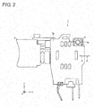
- Fig. 2 is a front view illustrating the configuration of trigger switch 1 of the first embodiment.
- Trigger switch 1 switch unit
- casing sealed casing
- Casing 2 is constructed with a combination of first casing member (first member: case) 2a and second casing member (second member: cover) 2b, which are of two casing members.
- Terminal unit 3 includes external terminals 4a and 4b and pressing member 5.
- external terminals 4a and 4b are terminals that are connected to lead wires connected to a motor of the electric tool.
- External terminals 4a and 4b project to the outside of casing 2.
- External terminals 4a and 4b are symmetrically located with respect to pressing member 5.
- External terminals 4a and 4b are connected to such an electric component as a switch and a wiring board in casing 2.
- FIGS. 3 to 5 are sectional views taken on line A-A in Fig. 2 , and illustrate first casing member 2a and second casing member 2b.
- Fig. 3 illustrates a state in which first casing member 2a and second casing member 2b are separated from each other
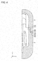
- Fig. 4 illustrates a state (fitted state) in which the pre-welding first casing member 2a and second casing member 2b are fitted in each other
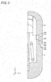
- Fig. 5 illustrate a state (welded state) after first casing member 2a and second casing member 2b are welded to each other.
- first casing member 2a includes engagement part (first engagement part, projecting portion) 21a, welding part (first welding part) 22a, burr reservoir forming part (first burr reservoir forming part) 23a, and contact part (first contact part) 24a.
- Second casing member 2b includes engagement part (second engagement part) 21b, welding part (second welding part) 22b, burr reservoir forming part (second burr reservoir forming part) 23b, and contact part (second contact part) 24b.
- casing 2 includes engagement part 21, welding part 22, burr reservoir 23, and contact part 24.
- Engagement part 21a and engagement part 21 b are engaged with each other in engagement part 21.
- Welding part 22 is formed by welding partially melted welding part 22a and welding part 22b by ultrasonic welding.
- Burr reservoir 23 is formed by burr reservoir forming part 23a and burr reservoir forming part 23b.
- Contact part 24a and contact part 24b are in contact with each other in contact part 24.
- Engagement part 21a and engagement part 21b are engaged with each other.
- Engagement part 21a has a shape projected in a positive direction of a Z-axis
- engagement part 21 b has a recessed shape.
- Engagement part 21a is located in an inner side in casing 2 with respect to welding part 22a, and extends upward (in a direction opposite to a burr outflow direction (described in detail later)) from welding part 22a. Therefore, a burr can be prevented from leaking into casing 2 when first casing member 2a and second casing member 2b are welded to each other.
- surfaces (vertical surfaces and horizontal surfaces) of engagement part 21a and engagement part 21b are not in contact with each other while being opposed to each other, but engagement part 21 may include a gap (clearance).
- Welding part 22a and welding part 22b are partially melted and welded to each other by the ultrasonic welding.
- Welding part 22a includes a surface oblique to an ultrasonic vibration direction (Z-axis direction).
- welding part 22a includes the surface oblique to a reference surface (described in detail later) of contact part 24a.
- the oblique surface of welding part 22a preferably ranges from 30 degrees to 60 degrees with respect to the Z-axis (or X-axis).
- Welding part 22b has a stepwise projected shape.
- Welding part 22b may include an oblique surface that is in surface contact with the oblique surface of welding part 22a. In the fitted state, welding part 22a and welding part 22b abut on each other, and the oblique surface of welding part 22a is in line contact with an end portion of welding part 22b.
- casing 2 can have the strength against the force in the direction perpendicular to the ultrasonic vibration direction.
- the sectional structure of one sidewall of casing 2 is illustrated in the first embodiment, all the sidewalls of casing 2 may have the sectional structure in Fig. 5 .
- casing 2 has a structure in Fig. 5 in which first casing member 2a and second casing member 2b are connected to each other in all the sidewalls.
- Burr reservoir forming part 23a and burr reservoir forming part 23b form burr reservoir 23 after first casing member 2a and second casing member 2b are welded to each other.
- Burr reservoir 23 is the gap formed between burr reservoir forming part 23a and burr reservoir forming part 23b. After the welding, the whole or part of burr reservoir 23 is filled with the burr generated from the melting of welding part 22a and welding part 22b. Preferably a volume of burr reservoir 23 is larger than the amount of burr generated from the melting of welding part 22a and welding part 22b. Burr reservoir 23 is located below welding part 22 (a negative direction of the Z-axis).
- burr reservoir 23 is located in the burr outflow direction in which the burr flows out from welding part 22.
- burr reservoir 23 is provided in an outer side in casing 2 with respect to welding part 22 (the positive direction of the X-axis). Therefore, the burr generated by the ultrasonic welding can be prevented from leaking into casing 2. Even if the burr is generated exceeding the volume of burr reservoir 23, because the burr leaks to the outside of the casing, a burr removing process can easily be performed without soiling the inside of casing 2.
- Contact part 24a includes a contact surface that comes into contact with contact part 24b.
- Contact part 24b has the projected shape, and a leading end surface of contact part 24b comes into surface contact with contact part 24a.
- the contact surface of contact part 24a is the reference surface that specifies a positional relationship between first casing member 2a and second casing member 2b after the welding. That is, contact part 24a has a function of a stopper that specifies an intrusion amount of second casing member 2b during the welding.
- the contact surface of contact part 24a is flush with the surface of burr reservoir forming part 23a, and the surface of burr reservoir forming part 23a is a bottom surface of burr reservoir 23.
- a metal mold used to form first casing member 2a can be formed into the simple shape having less unevenness compared with the case burr reservoir 23 is formed into the recessed shape.
- a width in the X-axis direction of the leading end surface of contact part 24b is larger than that in the X-axis direction of the surface formed by burr reservoir forming part 23a and contact part 24a.
- engagement part 21a, burr reservoir forming part 23a, and contact part 24a of first casing member 2a and engagement part 21 b, welding part 22b, burr reservoir forming part 23b, and contact part 24b of second casing member 2b are formed as the vertical surface or the horizontal surface (YZ-plane or XY-plane). Alternatively, these parts may have an angle with respect to the vertical surface or the horizontal surface.
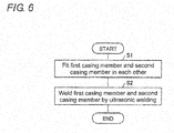
- FIG. 6 is a flowchart illustrating the method for producing casing 2 of the first embodiment.
- first casing member 2a and second casing member 2b are fitted in each other first (S1) as illustrated in Fig. 4 .
- welding part 22a of first casing member 2a and welding part 22b of second casing member 2b are welded to each other by applying a pressurizing force to second casing member 2b at the same time as an ultrasonic vibration (S2).
- casing 2 is shaped by removing the burr.
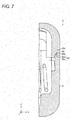
- FIG. 7 illustrates a sectional structure of a casing of the second embodiment after first and second casing members are welded to each other. Unless otherwise noted, the terms defined in the first embodiment are also used in the second embodiment according to the definitions.
- first casing member and second casing member 2d are welded to each other by a method in which the burr generated by the ultrasonic welding leaks above a welding part. Therefore, in the second embodiment, burr reservoir 23' is formed above welding part 22' of casing 2' as illustrated in Fig. 7 . Burr reservoir 23' is located in an outer side in welding part 22'.
- welding part 22c of first casing member 2c and welding part 22d of second casing member 2d include surfaces oblique to the ultrasonic vibration direction (Z-axis direction), and come into surface contact with each other.
- burr reservoir forming part 23c In burr reservoir forming part 23c, the surface opposed to burr reservoir forming part 23d is a planar surface. Burr reservoir forming part 23d has a recessed shape. Burr reservoir 23' is formed between burr reservoir forming part 23c and burr reservoir forming part 23d.
- the present invention can be used in a casing of electrical instruments such as an electric tool and an in-vehicle electrical instrument.
Landscapes
- Engineering & Computer Science (AREA)
- Mechanical Engineering (AREA)
- Microelectronics & Electronic Packaging (AREA)
- Lining Or Joining Of Plastics Or The Like (AREA)
- Pressure Welding/Diffusion-Bonding (AREA)
- Casings For Electric Apparatus (AREA)
- Switch Cases, Indication, And Locking (AREA)
Abstract
Description
- The present invention relates to a sealed casing that protects an electrical instrument and a method for producing the sealed casing.
- Conventionally, there are various techniques of ensuring sealability of the casing that protects the electrical instrument. For example, in Japanese Unexamined Patent Publication No.
2000-268663 - Nowadays, in order to achieve downsizing, weight reduction, and cost reduction of the electrical instrument, a thin casing is used to protect the electrical instrument. For the casing of an electric tool or the electrical instrument mounted on a vehicle, it is necessary to enhance sealability of the casing to improve dustproofness and waterproofness, and it is necessary to ensure strength to withstand vibration or shock on the casing.
- However, in the joining method of Japanese Unexamined Patent Publication No.
2000-268663 - An object of the present invention is to provide a sealed casing, which is used in an electrical instrument while the strength is improved, and a method for producing the sealed casing.
- In accordance with one aspect of the present invention, a sealed casing that is used in an electrical instrument includes: a first member; a second member; and a burr reservoir in which a burr generated by ultrasonic welding is reserved, the burr reservoir being located in a burr outflow direction in which the burr flows out from a welding part of the first member, the burr reservoir being a gap between the first member and the second member. The sealed casing is formed by welding the welding part and the second member by the ultrasonic welding, the welding part including a surface oblique to an ultrasonic vibration direction.
- At this point, a welding surface between the first member and the second member is formed so as to surround an inside of the sealed casing. Additionally, the welding surface is oblique to the ultrasonic vibration direction. Therefore, the direction of the welding surface varies depending on a place in the sealed casing. Accordingly, advantageously the sealed casing can withstand forces from all directions.
- According to the configuration, the gap formed between the first member and the second member constitutes the burr reservoir. Therefore, shapes of the first member and the second member can simply be designed compared with the case that the burr reservoir is formed in the first member or the second member.
- A surface of the first member may be flush with a contact surface of the first member, the surface of the first member being a bottom surface of the burr reservoir, the contact surface of the first member coming into contact with the second member to specify a positional relationship between the first member and the second member.
- According to the configuration, compared with the case that a recess is provided in the first member to form the burr reservoir, the first member can be formed into the simple shape having less unevenness. Therefore, a metal mold for the first member can be formed into the simple shape, and a lifetime of the metal mold for the first member can be lengthened.
- The burr reservoir may be located in an outer side in the sealed casing with respect to the welding part.
- According to the configuration, the burr reservoir is located in the outer side in the sealed casing with respect to the welding part, so that the burr can be prevented from leaking into the sealed casing.
- The first member may include a projecting portion that extends from the welding part toward a direction opposite to the burr outflow direction, the projecting portion being located in an inner side in the sealed casing with respect to the welding part.
- According to the configuration, the projecting portion extending from the welding part to the direction opposite to the burr outflow direction is located inside the sealed casing with respect to the welding part, so that the burr can be prevented from leaking into the sealed casing.
- In accordance with another aspect of the present invention, a sealed casing that is used in an electric tool includes: a first member; and a second member. The sealed casing is formed by welding a welding part of the first member and the second member by ultrasonic welding, the welding part including a surface oblique to an ultrasonic vibration direction.
- At this point, the welding surface between the first member and the second member is formed so as to surround the inside of the sealed casing. Additionally, the welding surface is oblique to the ultrasonic vibration direction. Therefore, the direction of the welding surface varies depending on the place in the sealed casing. Accordingly, advantageously the sealed casing can withstand forces from all directions.
- In accordance with still another aspect of the present invention, a method for producing a sealed casing used in an electrical instrument includes a step of forming the sealed casing by welding a first member and a second member by ultrasonic welding, the first member including: a first welding part that includes a surface oblique to an ultrasonic vibration direction; and a first burr reservoir forming part configured to form a gap with the second member as a burr reservoir after the ultrasonic welding, the first burr reservoir forming part being located in a burr outflow direction in which a burr generated by the ultrasonic welding flows out to the first welding part, the second member including: a second welding part that is welded to the first welding part; and a second burr reservoir forming part configured to form the gap with the first burr reservoir forming part as the burr reservoir after the ultrasonic welding.
- According to the present invention, the strength of the sealed casing used in an electrical instrument is advantageously improved.
-
-
Fig. 1 is a perspective view illustrating a configuration of a trigger switch according to a first embodiment of the present invention; -
Fig. 2 is a front view illustrating the configuration of the trigger switch; -
Fig. 3 is a sectional view illustrating first and second casing members constituting a casing of the trigger switch, and a state in which the first and second casing members are separated from each other; -
Fig. 4 is a sectional view illustrating the first and second casing members constituting the casing of the trigger switch, and a state in which the pre-welding first and second casing members are fitted in each other; -
Fig. 5 is a sectional view illustrating the first and second casing members constituting the casing of the trigger switch, and a state after the first and second casing members are welded to each other; -
Fig. 6 is a flowchart illustrating a method for producing the casing of the trigger switch; and -
Fig. 7 is a sectional view illustrating first and second casing members constituting a casing of a trigger switch according to a second embodiment of the present invention, and a state after the first and second casing members are welded to each other. - Hereinafter, exemplary embodiments of the present invention will be described in detail with reference to the drawings. In the description, a casing of an electric tool is described by way of example. More particularly, a casing of a trigger switch that is of a switch controlling power supplied to a motor of an electric tool is illustrated. However, the casing to which the present invention is applied is not limited to the casing of the trigger switch, but the present invention can be applied to any casing that protects electrical instruments such as an in-vehicle electrical instrument. Additionally, the present invention is not limited to the casing of the switch, but the present invention may be applied to a casing of another member constituting the electric tool. The present invention may be applied to a casing of the whole electric tool.
-
Fig. 1 is a perspective view illustrating a configuration of trigger switch 1 according to a first embodiment.Fig. 2 is a front view illustrating the configuration of trigger switch 1 of the first embodiment. Trigger switch 1 (switch unit) includes casing (sealed casing) 2 provided with a switch and a wiring board connected to the switch, terminal unit 3, and operation unit 6 (trigger) that turns on and off the switch from an outside ofcasing 2. Casing 2 is constructed with a combination of first casing member (first member: case) 2a and second casing member (second member: cover) 2b, which are of two casing members. - Terminal unit 3 includes
external terminals 4a and 4b and pressingmember 5. For example,external terminals 4a and 4b are terminals that are connected to lead wires connected to a motor of the electric tool.External terminals 4a and 4b project to the outside ofcasing 2.External terminals 4a and 4b are symmetrically located with respect to pressingmember 5.External terminals 4a and 4b are connected to such an electric component as a switch and a wiring board incasing 2. - The configurations of
first casing member 2a andsecond casing member 2b will be described below with reference toFigs. 3 to 5. Figs. 3 to 5 are sectional views taken on line A-A inFig. 2 , and illustratefirst casing member 2a andsecond casing member 2b.Fig. 3 illustrates a state in whichfirst casing member 2a andsecond casing member 2b are separated from each other,Fig. 4 illustrates a state (fitted state) in which the pre-weldingfirst casing member 2a andsecond casing member 2b are fitted in each other, andFig. 5 illustrate a state (welded state) afterfirst casing member 2a andsecond casing member 2b are welded to each other. - As illustrated in
Figs. 3 and4 ,first casing member 2a includes engagement part (first engagement part, projecting portion) 21a, welding part (first welding part) 22a, burr reservoir forming part (first burr reservoir forming part) 23a, and contact part (first contact part) 24a.Second casing member 2b includes engagement part (second engagement part) 21b, welding part (second welding part) 22b, burr reservoir forming part (second burr reservoir forming part) 23b, and contact part (second contact part) 24b. - As illustrated in
Fig. 5 ,casing 2 includesengagement part 21, weldingpart 22,burr reservoir 23, and contactpart 24.Engagement part 21a andengagement part 21 b are engaged with each other inengagement part 21. Weldingpart 22 is formed by welding partially meltedwelding part 22a andwelding part 22b by ultrasonic welding.Burr reservoir 23 is formed by burrreservoir forming part 23a and burrreservoir forming part 23b. Contactpart 24a and contactpart 24b are in contact with each other incontact part 24. -
Engagement part 21a andengagement part 21b are engaged with each other.Engagement part 21a has a shape projected in a positive direction of a Z-axis, andengagement part 21 b has a recessed shape.Engagement part 21a is located in an inner side incasing 2 with respect to weldingpart 22a, and extends upward (in a direction opposite to a burr outflow direction (described in detail later)) from weldingpart 22a. Therefore, a burr can be prevented from leaking intocasing 2 whenfirst casing member 2a andsecond casing member 2b are welded to each other. As illustrated inFigs. 4 and5 , in the fitted state and the welded state, surfaces (vertical surfaces and horizontal surfaces) ofengagement part 21a andengagement part 21b are not in contact with each other while being opposed to each other, butengagement part 21 may include a gap (clearance). - Welding
part 22a andwelding part 22b are partially melted and welded to each other by the ultrasonic welding. Weldingpart 22a includes a surface oblique to an ultrasonic vibration direction (Z-axis direction). In other words, weldingpart 22a includes the surface oblique to a reference surface (described in detail later) ofcontact part 24a. The oblique surface of weldingpart 22a preferably ranges from 30 degrees to 60 degrees with respect to the Z-axis (or X-axis). Weldingpart 22b has a stepwise projected shape. Weldingpart 22b may include an oblique surface that is in surface contact with the oblique surface of weldingpart 22a. In the fitted state, weldingpart 22a andwelding part 22b abut on each other, and the oblique surface of weldingpart 22a is in line contact with an end portion of weldingpart 22b. - When welding
part 22a includes the oblique surface, a force in the direction (in the drawings, the X-axis direction) perpendicular to the ultrasonic vibration direction (Z-axis direction) is not matched with shear directions offirst casing member 2a andsecond casing member 2b. Therefore, casing 2 can have the strength against the force in the direction perpendicular to the ultrasonic vibration direction. Although the sectional structure of one sidewall ofcasing 2 is illustrated in the first embodiment, all the sidewalls ofcasing 2 may have the sectional structure inFig. 5 . In this case, casing 2 has a structure inFig. 5 in whichfirst casing member 2a andsecond casing member 2b are connected to each other in all the sidewalls. Therefore, even if the force in which the direction is matched with the shear direction is applied tocasing 2 in a certain sidewall, the direction of the force is not matched with the shear direction in other sidewalls, so that casing 2 can have the strength against the force in any direction. - Burr
reservoir forming part 23a and burrreservoir forming part 23b formburr reservoir 23 afterfirst casing member 2a andsecond casing member 2b are welded to each other.Burr reservoir 23 is the gap formed between burrreservoir forming part 23a and burrreservoir forming part 23b. After the welding, the whole or part ofburr reservoir 23 is filled with the burr generated from the melting of weldingpart 22a andwelding part 22b. Preferably a volume ofburr reservoir 23 is larger than the amount of burr generated from the melting of weldingpart 22a andwelding part 22b.Burr reservoir 23 is located below welding part 22 (a negative direction of the Z-axis). The burr generated by the ultrasonic welding flows out below welding part 22 (in the gravitational direction), namely,burr reservoir 23 is located in the burr outflow direction in which the burr flows out from weldingpart 22. Preferablyburr reservoir 23 is provided in an outer side incasing 2 with respect to welding part 22 (the positive direction of the X-axis). Therefore, the burr generated by the ultrasonic welding can be prevented from leaking intocasing 2. Even if the burr is generated exceeding the volume ofburr reservoir 23, because the burr leaks to the outside of the casing, a burr removing process can easily be performed without soiling the inside ofcasing 2. - Contact
part 24a includes a contact surface that comes into contact withcontact part 24b. Contactpart 24b has the projected shape, and a leading end surface ofcontact part 24b comes into surface contact withcontact part 24a. The contact surface ofcontact part 24a is the reference surface that specifies a positional relationship betweenfirst casing member 2a andsecond casing member 2b after the welding. That is,contact part 24a has a function of a stopper that specifies an intrusion amount ofsecond casing member 2b during the welding. The contact surface ofcontact part 24a is flush with the surface of burrreservoir forming part 23a, and the surface of burrreservoir forming part 23a is a bottom surface ofburr reservoir 23. Therefore, a metal mold used to formfirst casing member 2a can be formed into the simple shape having less unevenness compared with thecase burr reservoir 23 is formed into the recessed shape. In order to formburr reservoir 23, a width in the X-axis direction of the leading end surface ofcontact part 24b is larger than that in the X-axis direction of the surface formed by burrreservoir forming part 23a and contactpart 24a. - In the first embodiment,
engagement part 21a, burrreservoir forming part 23a, and contactpart 24a offirst casing member 2a andengagement part 21 b, weldingpart 22b, burrreservoir forming part 23b, and contactpart 24b ofsecond casing member 2b are formed as the vertical surface or the horizontal surface (YZ-plane or XY-plane). Alternatively, these parts may have an angle with respect to the vertical surface or the horizontal surface. - A method for producing
casing 2 will be described with reference toFig. 6. Fig. 6 is a flowchart illustrating the method for producingcasing 2 of the first embodiment. - As illustrated in
Fig. 6 ,first casing member 2a andsecond casing member 2b are fitted in each other first (S1) as illustrated inFig. 4 . In the fitted state, weldingpart 22a offirst casing member 2a andwelding part 22b ofsecond casing member 2b are welded to each other by applying a pressurizing force tosecond casing member 2b at the same time as an ultrasonic vibration (S2). - In the case that the burr leaks to the outside of
casing 2 after the welding,casing 2 is shaped by removing the burr. - A second embodiment of the present invention will be described below with reference to
Fig. 7. Fig. 7 illustrates a sectional structure of a casing of the second embodiment after first and second casing members are welded to each other. Unless otherwise noted, the terms defined in the first embodiment are also used in the second embodiment according to the definitions. - In the second embodiment, first casing member and second casing member 2d are welded to each other by a method in which the burr generated by the ultrasonic welding leaks above a welding part. Therefore, in the second embodiment, burr reservoir 23' is formed above welding part 22' of casing 2' as illustrated in
Fig. 7 . Burr reservoir 23' is located in an outer side in welding part 22'. - In the second embodiment, welding
part 22c of first casing member 2c andwelding part 22d of second casing member 2d include surfaces oblique to the ultrasonic vibration direction (Z-axis direction), and come into surface contact with each other. - In burr
reservoir forming part 23c, the surface opposed to burrreservoir forming part 23d is a planar surface. Burrreservoir forming part 23d has a recessed shape. Burr reservoir 23' is formed between burrreservoir forming part 23c and burrreservoir forming part 23d. - The present invention is not limited to the embodiments, but various changes can be made without departing from the scope of the claims. It is noted that an embodiment obtained by a proper combination of technical means disclosed in different embodiments is also included in the technical scope of the present invention.
- The present invention can be used in a casing of electrical instruments such as an electric tool and an in-vehicle electrical instrument.
Claims (6)
- A sealed casing that is used in an electric instrument, the sealed casing (2) comprising:a first member (2a); anda second member (2b),wherein the sealed casing (2) is formed by welding a welding part (22a) of the first member (2a) and the second member (2b) by ultrasonic welding, the welding part comprising a surface oblique to an ultrasonic vibration direction.
- The sealed casing according to claim 1, further comprising:a burr reservoir (23) in which a burr generated by ultrasonic welding is reserved, the burr reservoir (23) being located in a burr outflow direction in which the burr flows out from the welding part (22a) of the first member (2a), the burr reservoir (23) being a gap between the first member (2a) and the second member (2b).
- The sealed casing according to claim 2, wherein a surface of the first member (2a) is flush with a contact surface of the first member (2a), the surface of the first member (2a) being a bottom surface of the burr reservoir (23), the contact surface of the first member (2a) coming into contact with the second member (2b) to specify a positional relationship between the first member (2a) and the second member (2b).
- The sealed casing according to claim 2 or 3, wherein the burr reservoir (23) is located in an outer side in the sealed casing with respect to the welding part.
- The sealed casing according to any one of claims 2 to 4, wherein the first member (2a) comprises a projecting portion that extends from the welding part toward a direction opposite to the burr out-flow direction, the projecting portion being located in an inner side in the sealed casing with respect to the welding part.
- A method for producing a sealed casing (2) used in an electrical instrument, the method comprising:a step of forming the sealed casing (2) by welding a first member (2a) and a second member (2b) by ultrasonic welding,the first member (2a) comprising: a first welding part that comprises a surface oblique to an ultrasonic vibration direction; and a first burr reservoir forming part (23a) configured to form a gap with the second member (2b) as a burr reservoir (23) after the ultrasonic welding, the first burr reservoir forming part (23a) being located in a burr out-flow direction in which a burr generated by the ultrasonic welding flows out to the first welding part,the second member (2b) comprising: a second welding part that is welded to the first welding part (22a); and a second burr reservoir forming part (23b) configured to form the gap with the first burr reservoir forming part (23a) as the burr reservoir (23) after the ultrasonic welding.
Applications Claiming Priority (1)
| Application Number | Priority Date | Filing Date | Title |
|---|---|---|---|
| JP2013139182A JP2015009551A (en) | 2013-07-02 | 2013-07-02 | Sealed casing and production method thereof |
Publications (1)
| Publication Number | Publication Date |
|---|---|
| EP2822014A1 true EP2822014A1 (en) | 2015-01-07 |
Family
ID=51205154
Family Applications (1)
| Application Number | Title | Priority Date | Filing Date |
|---|---|---|---|
| EP14172526.7A Withdrawn EP2822014A1 (en) | 2013-07-02 | 2014-06-16 | Sealed casing and production method thereof |
Country Status (4)
| Country | Link |
|---|---|
| US (1) | US20150014006A1 (en) |
| EP (1) | EP2822014A1 (en) |
| JP (1) | JP2015009551A (en) |
| CN (1) | CN104284546A (en) |
Cited By (2)
| Publication number | Priority date | Publication date | Assignee | Title |
|---|---|---|---|---|
| EP3576506A1 (en) * | 2018-05-31 | 2019-12-04 | Apple Inc. | Double shear weld joint for electronic enclosures |
| EP3576505A1 (en) * | 2018-05-31 | 2019-12-04 | Apple Inc. | Dual cup enclosure for electronic devices |
Families Citing this family (8)
| Publication number | Priority date | Publication date | Assignee | Title |
|---|---|---|---|---|
| CN105984118B (en) * | 2015-02-06 | 2022-05-10 | 上海鸿研物流技术有限公司 | Anti-overflow structure |
| US10375846B2 (en) * | 2017-01-13 | 2019-08-06 | Lite-On Electronics (Guangzhou) Limited | Housing having housing parts bondable together and method of manufacturing the same |
| US10477710B2 (en) * | 2017-01-13 | 2019-11-12 | Lite-On Electronics (Guangzhou) Limited | Electronic module with an improved shell and method for making the same |
| JP6555726B2 (en) * | 2017-02-23 | 2019-08-07 | 有限会社ハヤシ商店 | Waist bag |
| JP6899245B2 (en) * | 2017-04-07 | 2021-07-07 | 日清紡メカトロニクス株式会社 | Turbofan |
| US10622752B2 (en) | 2018-05-31 | 2020-04-14 | Apple Inc. | Ultrasonic weld joint with integral flash trap |
| TWI739702B (en) * | 2020-12-31 | 2021-09-11 | 群光電能科技股份有限公司 | Welding structures on two objects for connection |
| JP2023044746A (en) * | 2021-09-21 | 2023-04-03 | 株式会社デンソーテン | On-vehicle equipment housing |
Citations (3)
| Publication number | Priority date | Publication date | Assignee | Title |
|---|---|---|---|---|
| GB2307440A (en) * | 1995-11-24 | 1997-05-28 | Niles Parts Co Ltd | Ultrasonically welded case |
| JP2000268663A (en) | 1999-03-18 | 2000-09-29 | Nihon Kaiheiki Industry Co Ltd | Closed-type small-sized switch |
| US20080278045A1 (en) * | 2007-05-10 | 2008-11-13 | Delta Electronics, Inc. | Case assembly structure of electronic device |
Family Cites Families (5)
| Publication number | Priority date | Publication date | Assignee | Title |
|---|---|---|---|---|
| JP4509370B2 (en) * | 2000-12-26 | 2010-07-21 | ナイルス株式会社 | Sealed bonded structure of resin structure |
| DE10138482A1 (en) * | 2001-08-04 | 2003-02-13 | Bosch Gmbh Robert | Joining together two, typically plastic, parts, particularly the parts of an insertion sensor to be inserted into a pipeline using vibration or ultrasonic welding with welding pockets between the two parts for excess material |
| CN201112433Y (en) * | 2007-10-26 | 2008-09-10 | 惠州市德赛电池有限公司 | Water-proof package battery casing |
| US7767920B1 (en) * | 2009-03-04 | 2010-08-03 | Niles America Wintech, Inc. | Switch and welding method of same |
| CN102858119A (en) * | 2011-07-01 | 2013-01-02 | 莱尔德电子材料股份有限公司 | Ultrasonic welding type wire structure, welding method, product shell and electronic product |
-
2013
- 2013-07-02 JP JP2013139182A patent/JP2015009551A/en active Pending
-
2014
- 2014-06-16 EP EP14172526.7A patent/EP2822014A1/en not_active Withdrawn
- 2014-06-17 US US14/306,751 patent/US20150014006A1/en not_active Abandoned
- 2014-06-30 CN CN201410306446.7A patent/CN104284546A/en active Pending
Patent Citations (3)
| Publication number | Priority date | Publication date | Assignee | Title |
|---|---|---|---|---|
| GB2307440A (en) * | 1995-11-24 | 1997-05-28 | Niles Parts Co Ltd | Ultrasonically welded case |
| JP2000268663A (en) | 1999-03-18 | 2000-09-29 | Nihon Kaiheiki Industry Co Ltd | Closed-type small-sized switch |
| US20080278045A1 (en) * | 2007-05-10 | 2008-11-13 | Delta Electronics, Inc. | Case assembly structure of electronic device |
Cited By (6)
| Publication number | Priority date | Publication date | Assignee | Title |
|---|---|---|---|---|
| EP3576506A1 (en) * | 2018-05-31 | 2019-12-04 | Apple Inc. | Double shear weld joint for electronic enclosures |
| EP3576505A1 (en) * | 2018-05-31 | 2019-12-04 | Apple Inc. | Dual cup enclosure for electronic devices |
| CN110557032A (en) * | 2018-05-31 | 2019-12-10 | 苹果公司 | Dual cup housing for an electronic device |
| US10505308B1 (en) | 2018-05-31 | 2019-12-10 | Apple Inc. | Dual cup enclosure for electronic devices |
| US10587070B2 (en) | 2018-05-31 | 2020-03-10 | Apple Inc. | Double shear weld joint for electronic enclosure |
| CN110557032B (en) * | 2018-05-31 | 2021-03-23 | 苹果公司 | Dual cup housing for electronic device and method of forming the same |
Also Published As
| Publication number | Publication date |
|---|---|
| CN104284546A (en) | 2015-01-14 |
| JP2015009551A (en) | 2015-01-19 |
| US20150014006A1 (en) | 2015-01-15 |
Similar Documents
| Publication | Publication Date | Title |
|---|---|---|
| EP2822014A1 (en) | Sealed casing and production method thereof | |
| CN104883849B (en) | The seal construction of electronic control unit | |
| KR101729809B1 (en) | Electronic control device | |
| JP6797123B2 (en) | Electrical circuit equipment | |
| US10451677B2 (en) | Battery state sensing device and manufacturing method therefor | |
| JPWO2017204084A1 (en) | Flexible flat cable connector, flexible flat cable connection structure, and rotary connector device | |
| JP2013038051A (en) | Connector with capacitor | |
| JP2015060958A (en) | Lead frame, electronic control device using lead frame, and lead frame mounting method | |
| CN104145376A (en) | Electrical connector | |
| CN103227066A (en) | Connection structure of housing of electronic apparatus and connection method of forming housing | |
| JP2014187728A (en) | Electronic controller | |
| JP2017069317A (en) | Noise reduction device | |
| JP2008124244A (en) | Electronic component and electronic control device using the same | |
| JP2017103848A (en) | Electric motor, in-vehicle device equipped with the same, and terminal connection structure | |
| JP2012242195A (en) | Magnetic detection device | |
| JP6354594B2 (en) | Electronic equipment | |
| JP2010186563A (en) | Electronic control device | |
| JP2011117853A (en) | Current detector | |
| JP2016111884A (en) | Motor and mechatronic motor including the same | |
| JP2017077149A (en) | Electric motor, in-vehicle device including the same, inspection device, and power input unit inspection method | |
| JP2013235968A (en) | Capacitor mounting structure | |
| JP2017223226A (en) | Reciprocating compressor and process for mounting airtight sealed housing of reciprocating compressor | |
| JP5746500B2 (en) | Bus bar and electrical junction box provided with the same | |
| JP2016092086A (en) | Case structure | |
| JP6209997B2 (en) | In-vehicle electrical equipment |
Legal Events
| Date | Code | Title | Description |
|---|---|---|---|
| PUAI | Public reference made under article 153(3) epc to a published international application that has entered the european phase |
Free format text: ORIGINAL CODE: 0009012 |
|
| 17P | Request for examination filed |
Effective date: 20140616 |
|
| AK | Designated contracting states |
Kind code of ref document: A1 Designated state(s): AL AT BE BG CH CY CZ DE DK EE ES FI FR GB GR HR HU IE IS IT LI LT LU LV MC MK MT NL NO PL PT RO RS SE SI SK SM TR |
|
| AX | Request for extension of the european patent |
Extension state: BA ME |
|
| R17P | Request for examination filed (corrected) |
Effective date: 20150630 |
|
| RBV | Designated contracting states (corrected) |
Designated state(s): AL AT BE BG CH CY CZ DE DK EE ES FI FR GB GR HR HU IE IS IT LI LT LU LV MC MK MT NL NO PL PT RO RS SE SI SK SM TR |
|
| STAA | Information on the status of an ep patent application or granted ep patent |
Free format text: STATUS: REQUEST FOR EXAMINATION WAS MADE |
|
| STAA | Information on the status of an ep patent application or granted ep patent |
Free format text: STATUS: THE APPLICATION IS DEEMED TO BE WITHDRAWN |
|
| 18D | Application deemed to be withdrawn |
Effective date: 20170103 |