EP2822154A2 - Bürstenplatte und Elektromotor damit - Google Patents
Bürstenplatte und Elektromotor damit Download PDFInfo
- Publication number
- EP2822154A2 EP2822154A2 EP14168206.2A EP14168206A EP2822154A2 EP 2822154 A2 EP2822154 A2 EP 2822154A2 EP 14168206 A EP14168206 A EP 14168206A EP 2822154 A2 EP2822154 A2 EP 2822154A2
- Authority
- EP
- European Patent Office
- Prior art keywords
- base plate
- brush
- plate
- electrical module
- hook
- Prior art date
- Legal status (The legal status is an assumption and is not a legal conclusion. Google has not performed a legal analysis and makes no representation as to the accuracy of the status listed.)
- Withdrawn
Links
- OKTJSMMVPCPJKN-UHFFFAOYSA-N Carbon Chemical compound [C] OKTJSMMVPCPJKN-UHFFFAOYSA-N 0.000 claims description 15
- 229910052799 carbon Inorganic materials 0.000 claims description 15
- RYGMFSIKBFXOCR-UHFFFAOYSA-N Copper Chemical compound [Cu] RYGMFSIKBFXOCR-UHFFFAOYSA-N 0.000 description 2
- 230000000295 complement effect Effects 0.000 description 2
- 229910052802 copper Inorganic materials 0.000 description 2
- 239000010949 copper Substances 0.000 description 2
- 230000000694 effects Effects 0.000 description 2
- 238000005728 strengthening Methods 0.000 description 2
- 208000032365 Electromagnetic interference Diseases 0.000 description 1
- 230000009286 beneficial effect Effects 0.000 description 1
- 238000004519 manufacturing process Methods 0.000 description 1
- 230000013011 mating Effects 0.000 description 1
- 238000012986 modification Methods 0.000 description 1
- 230000004048 modification Effects 0.000 description 1
- 238000003466 welding Methods 0.000 description 1
Images


Classifications
-
- H—ELECTRICITY
- H02—GENERATION; CONVERSION OR DISTRIBUTION OF ELECTRIC POWER
- H02K—DYNAMO-ELECTRIC MACHINES
- H02K11/00—Structural association of dynamo-electric machines with electric components or with devices for shielding, monitoring or protection
- H02K11/02—Structural association of dynamo-electric machines with electric components or with devices for shielding, monitoring or protection for suppression of electromagnetic interference
- H02K11/026—Suppressors associated with brushes, brush holders or their supports
-
- H—ELECTRICITY
- H02—GENERATION; CONVERSION OR DISTRIBUTION OF ELECTRIC POWER
- H02K—DYNAMO-ELECTRIC MACHINES
- H02K23/00—DC commutator motors or generators having mechanical commutator; Universal AC/DC commutator motors
- H02K23/66—Structural association with auxiliary electric devices influencing the characteristic of, or controlling, the machine, e.g. with impedances or switches
-
- H—ELECTRICITY
- H02—GENERATION; CONVERSION OR DISTRIBUTION OF ELECTRIC POWER
- H02K—DYNAMO-ELECTRIC MACHINES
- H02K5/00—Casings; Enclosures; Supports
- H02K5/04—Casings or enclosures characterised by the shape, form or construction thereof
- H02K5/14—Means for supporting or protecting brushes or brush holders
- H02K5/143—Means for supporting or protecting brushes or brush holders for cooperation with commutators
- H02K5/148—Slidably supported brushes
Definitions
- the present invention relates to an electrical motor, especially to how to secure a module of an electrical motor having a carbon brush on a brush plate.
- An EMC module is widely adopted in modem vehicle parts such as wiper motors, sunroof motors or the like.
- the EMC module is mainly used to prevent the motor from being influenced by electromagnetic interferences resulted from other vehicle electric parts or inhibit electromagnetic interference of the motor itself. Therefore, the EMC module is necessary for the wiper motor.
- the EMC module is loosely mounted in the wiper motor, especially on a brush plate thereof, in such a way that the EMC module is slightly movable on the brush plate.
- the conventional EMC module is manufactured and mounted on the brush plate such that it can be moved along a single direction.
- the brush plate together with the EMC module is transported for example to a manufacturing shop from a supplier or even when the motor is being operated, the EMC module can possibly be moved relative to the brush plate and thus can be damaged.
- the present invention proposes a brush plate for a motor, especially for a wiper motor on which an EMC module is securely held using an improved securing arrangement. Therefore, the EMC module can be fixed relative to the brush plate during transportation thereof such that no movement can occur between them.
- a brush plate comprising a base plate and an electrical module carried by the base plate
- the electrical module is installed on the base plate by means of a sliding pair such that the electrical module is lockable on the base plate at a terminal point of the sliding pair along an installing direction thereof.
- the electrical module is an EMC module.
- the base plate is substantially in the shape of a ring, and the installing direction is substantially consistent with a radial direction of the base plate.
- an opening is provided on an inner or outer ring edge of the ring-shaped base plate
- the electrical module comprises two sockets and at lease one hook, opposite edges of the opening are matched movably within the sockets so as to constitute the sliding pair, and the hook is lockable to a ring edge opposite the ring edge provided with the opening.
- the ring edge, to which the hook is lockable is provided with a notch, and the hook is lockable in the notch.
- the base plate is substantially in the shape of a ring, and the installing direction is substantially consistent with a thickness direction of the base plate.
- an opening is provided between inner and outer ring edges of the ring-shaped base plate, and the electrical module is inserted partly through the opening and matched movably in it so as to constitute the sliding pair.
- At least one hook is provided on the base plate adjacent the opening, a portion of the electrical module is abutted against the ring-shaped base plate, and the hook is lockable to the electrical module.
- the hook extends substantially perpendicular from the base plate.
- the electrical module has a longitudinal installing direction substantially perpendicular to the base plate.
- the brush plate comprises a brush holder installed on the base plate, a carbon in the brush holder is able to connect electrically with the electrical module via a strand.
- the electrical module comprises a choke which has a longitudinal installing direction substantially perpendicular to the base plate after the electrical module is locked to the base plate.
- a vehicle motor especially a wiper motor or a skylight motor
- the motor has a rotor, a slip ring disposed coaxially relative to the rotor and a carbon brush contacting with the slip ring, the motor further comprises the brush plate mentioned above, and the carbon brush is mounded in the brush plate.
- the EMC module is directly locked to the brush plate without any other securing tools such as screws, hot riveting welding or the like. Therefore, the EMC module is fixed to the brush plate in a relatively simple and cheap manner.
- FIG. 1 schematically shows a plan view of a brush plate assembled with an EMC module 2 according to a first embodiment of the present invention.
- the brush plate comprises a base plate 1.
- the base plate 1 is made of plastic.
- the EMC module 2 has a main body made of plastic.
- the base plate 1 is substantially in the shape of a thin ring.
- the base plate 1 is adapted to electric motors of vehicle, such as wiper motors, sunroof motors or the like.
- Each brush holder 3 is used to receive a carbon brush. It is appreciated that each brush holder 3 can be integral with the brush plate 1.
- the EMC module 2 is secured on the base plate 1 between the two brush holders 3.
- the EMC module has a longitudinal mounting direction substantially perpendicular to the base plate.
- an electrical motor especially a wiper motor or a sunroof motor, of a vehicle has a rotor, a slip ring disposed coaxially relative to the rotor and a carbon brush contacting with the slip ring.
- the brush plate according to the present invention can be provided in the motor.
- the brush holder can be disposed on the brush plate.
- the carbon brush is disposed in the brush holder.
- FIG. 2 schematically shows a partial perspective view of the base plate 1 assembled with the EMC module 2.
- EMC module 2 two chokes 4 are installed. Each choke 4 is used to connect with a copper strand of the respective carbon brush such that the choke 4 electrically contacts with the carbon brush. It is known that, in addition to the helical chokes 4, other necessary electrical and/or mechanical parts can be received in the main body of the EMC module 2.
- the technical problem aimed to be solved by the present invention is how to secure the EMC module 2 relative to the base plate 1 firmly and the following explanations will focus on this.
- the EMC module 2 generally comprises a first securing part 5, which is used to secure the EMC module 2 on the base plate 1.
- the first securing part 5 is a part of the main body of the EMC module 2.
- the first securing part 5 is substantially I-shaped.
- the first securing part 5 is provided with two projections 5a, 5b and 5c, 5d at opposite lateral sides respectively. That is, a pair of projections 5a and 5b are located at one lateral side of the first securing part 5 and a pair of projections 5c and 5d are located at the other lateral side.
- the two pairs of projections 5a, 5b and 5c, 5d extend in the width direction of the EMC module 2 and are far away from each other.
- a gap is formed between each pair of projections 5a, 5b and 5c, 5d.
- the gap has a size substantially corresponding to or slightly less than the thickness of the base plate 1. Therefore, at each lateral side of the first securing part 5, a fork-shaped socket is formed by the respective pair of projections.
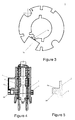
- FIG 3 schematically shows a plan view of only the base plate 1.
- the base plate 1 is formed with a rectangular notch 1a.
- the notch 1a opens radially and outwardly.
- the notch 1a occupies a large portion of the width of the ring-shaped base plate 1.
- the notch 1a is mainly used to receive the main body of the EMC module 2.
- the notch 1a has a width substantially corresponding to a vertical distance between both bases of the two fork-shaped sockets on the lateral sides of the first securing part 5. Therefore, as shown in figures 1 and 2 , when the EMC module 2 is assembled onto the base plate 1, the fork-shaped sockets can be clamped about opposite edges of the notch 1a.
- the projections 5a, 5c and 5b, 5d bear against upper and lower surfaces of the ring-shaped base plate 1 respectively. That is, the assembled EMC module 2 is restrained on the base plate 1 in two directions, i.e. the circumferential direction of the ring-shaped base plate 1 and a direction perpendicular to the plane of the base plate 1.
- the base plate 1 is also provided with a little rectangular notch 1b which is opposed to the notch 1a along the width direction of the ring-shaped base plate 1.
- the notch 1b opens radially and inwardly.
- the rectangular notch 1b has a size greatly less than the notch 1a.
- the notch 1b is middle circumferentially relative to the notch 1a.
- the notch 1b can be provided such that it is offset towards one end of the notch 1a.
- the base plate 1 is illustrated with some other shaped openings. It should be understood that those other shaped openings are adapted to other functions of the base plate.
- the base plate 1 can be a base plate having any other suitable functional characters.
- Figure 4 schematically shows a cross-sectional view obtained along a section A-A illustrated in figure 1 .
- the main body of the EMC module 2 is also provided with a second securing part 6.
- the second securing part 6 is apart from the first securing part 5 with respect to a longitudinal axis of the main body of the EMC module 2.
- the second securing part 6 comprises a cantilever 6a extending therefrom in a direction apart from the first securing part 5, which cantilever is substantially perpendicular to the longitudinal axis of the main body of the EMC module 2.
- a hook 6b extends in parallel with the longitudinal axis of the main body of the EMC module 2 from one end of the cantilever 6a.
- the hook 6b of the second securing part 6 of the EMC module 2 can be hooked into the notch 1b in such a way that the EMC module 2 is restrained radially on the brush plate 1.
- the hook 6b is hooked into the notch 1b on the upper surface of the brush plate 1.
- the hook 6b can be hooked into the notch 1b on the lower surface of the base plate 1.
- the hook 6b passes over the upper or lower surface of the base plate 1.
- the hook 6b is just locked into the notch 1b. Therefore, according to the configuration described above, after the EMC module 2 is assembled onto the base plate 1, the former can be securely fixed to the latter. No movement can occur between them.
- the notch 1b has a substantially straight wall for engaging with the hook 6b of the EMC module 2.
- the notch 1b and the hook 6b can be configured in many other or various ways.
- figure 5 shows an alternative embodiment how the EMC module 2 is fixed to the base plate 1. This embodiment is distinguished from the first embodiment only in that the EMC module 2 is provided with a hook 6c which is shaped in a manner complementary to an engaging wall of the notch 1b.
- the second securing part 6 of the EMC module 2 has a hook 6c extending from the cantilever 6a in parallel with the longitudinal axis of the main body of the EMC module 2.
- the hook 6c has an oblique wall which is tilted relative to the cantilever 6a of the second securing part 6.
- the notch 1b has a mating oblique wall which is tilted relative to the plane of the base plate 1 in the same slope of the hook 6c. Therefore, when the EMC module 2 is assembled onto base plate 1, the oblique wall of the hook 6c is easily snapped onto the oblique wall of the notch 1b after the edge of the hook 6c passes radially over the edge of the notch 1b.
- the hook 6c is formed with a wedge-shaped groove for engaging with a complementary wedge-shaped edge of the notch 1b such that the EMC module 2 is secured on the brush plate 1 not only radially but also longitudinally (i.e. in the height direction of the EMC module 2).
- more than one hook 6b, 6c can be provided on the second securing part 6 of the EMC module 2 and correspondingly more than one notch 1b can be provided in the brush plate 1.
- two or more hooks 6b, 6c apart from each other are provided on the second securing part 6 so as to engage with respective notches 1b in the brush plate 1.
- the oblique wall of the hook 6c is shorter than the oblique wall of the notch 1b, as illustrated in figure 5 .
- the notches 1a and 1b can be reversed with respect to each other.
- the notch 1a is provided on the inner edge of the ring-shaped brush plate 1 and opens radially and inwardly
- the notch 1b is provided on the outer edge of the ring-shaped brush plate 1 and opens radially and outwardly.
- the EMC module is installed on the base plate by means of a sliding pair.
- the EMC module is lockable to the base plate at a terminal point of the sliding pair in an installing direction thereof. That is, after the EMC module is moved into place by means of the sliding pair along the installing direction, the EMC module is locked and snapped onto the base plate.
- the installing direction extends substantially along a radial direction of the base plate. For instance, in the above embodiment, after the EMC module is moved into place along the radial direction of the base plate from an outer periphery to an inner periphery of the base plate, the EMC module is locked on the base plate via the hook and the socket.
- the EMC module can be designed such that, after it is moved into place along the radial direction of the base plate from the inner periphery to the outer periphery of the base plate, the EMC module is locked onto the base plate via the hook and the socket.
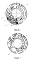
- Figure 6 schematically shows a plan view of a base plate 10 assembled with an EMC module 20 according to a second embodiment of the present invention.
- the base plate 10 is made of plastic.
- the EMC module 20 has a main body made of plastic.
- the base plate 10 is substantially in the shape of a thin ring.
- Each brush holder 30 is used to receive a carbon brush. It is appreciated that each brush holder 30 can be integral with the base plate 10.
- the EMC module 20 is secured on the base plate 10 between the two brush holders 30.
- two chokes 40 are installed in the EMC module 20. Each choke 40 is used to connect with a copper strand of the respective carbon brush such that the choke 40 electrically contacts with the carbon brush. It is known that, in addition to the chokes 40, other necessary electrical and/or mechanical parts can be received in the main body of the EMC module 20.
- FIG. 7 schematically shows a plan view of only the base plate 10 according to the second embodiment of the present invention.
- the ring-shaped base plate 10 comprises a rectangular opening 10a which is enclosed by edges.
- the opening 10a defines a substantially rectangular shape with some of its edges such that the opening 10a can receive the main body of the EMC module 20. Therefore, when the EMC module 20 is inserted into the opening 10a of the brush plate 10, some walls of the main body of the EMC module 20 can be pressed against the illustrated and flat edges (walls) of the opening 10a such that the EMC module 20 is restrained in the plane where the base plate 10 is located. That is, the EMC module 20 is immovable in this plane.
- design of the opening 10a enables the base plate 10 to have a greater strength because the opening 10 does not extend to the outer or inner edge of the ring-shaped base plate 10.
- a securing part 10b is integrally provided on the base plate 10 adjacent one edge of the opening 10a. As shown in figure 8 , the securing part 10b extends perpendicular to the plane where the brush plate 10 is located. Formed at a free end of the securing part 10b is a hook 10c. The hook 10c is used to lock the EMC module 20 on the base plate 10 in the height direction of the EMC module 20.
- the main body of the EMC module 20 is provided with a securing part 20a.
- the securing part 20a is in the shape of a boss projecting perpendicular to a longitudinal axis of the EMC module 20.
- the boss-shaped securing part 20a has a width which can be slightly greater than the width of the opening 10a of the base plate 10 such that, after the EMC module 20 is assembled onto the base plate 10, at least a portion of the securing part 20a can be used to abut a surface of the base plate 10.
- the hook 10c of the brush plate 10 has a face 10d for engaging with the boss-shaped securing part 20a of the main body of the EMC module 20.
- the boss-shaped securing part 20a of the EMC module 20 has a face 20b for engaging with the face 10d of the hook 10c.
- the distance between the face 10d and the surface of the base plate 10, which the securing part 20a abuts, is substantially equal to the distance between the face 20b and a face of the securing part 20a via which the securing part 20a abuts the surface of the base plate 10.
- the face 10d of the hook 10c of the base plate 10 is engaged with the face 20b of the securing part 20a with another parallel face of the securing part 20a abutting the surface of the base plate 10.
- the EMC module 20 is secured on the base plate 10 in the height direction. Therefore, by the opening 10a and the hook 10c of the base plate 10 cooperating with the securing part 20a of the EMC module 20, the EMC module 20 can be securely fixed to the base plate 10.
- the installing direction is consistent substantially with a thickness direction of the base plate.
- the EMC module is inserted into the base plate from top to bottom along the thickness direction of the base plate and then is locked in the base plate via the hook. It is appreciated that the EMC module can be also designed in such a way that it is inserted into the base plate from bottom to top along the thickness direction of the base plate and then is locked in the base plate via the hook.
- hook 10c of the base plate 10 and the securing part 20a of the EMC module 20 can be shaped similarly as shown in figure 5 .
Landscapes
- Engineering & Computer Science (AREA)
- Power Engineering (AREA)
- Physics & Mathematics (AREA)
- Electromagnetism (AREA)
- Motor Or Generator Current Collectors (AREA)
- Motor Or Generator Frames (AREA)
Applications Claiming Priority (1)
| Application Number | Priority Date | Filing Date | Title |
|---|---|---|---|
| CN201310278784.XA CN104283374A (zh) | 2013-07-04 | 2013-07-04 | 刷架板以及安装有刷架板的电机 |
Publications (2)
| Publication Number | Publication Date |
|---|---|
| EP2822154A2 true EP2822154A2 (de) | 2015-01-07 |
| EP2822154A3 EP2822154A3 (de) | 2016-01-13 |
Family
ID=50687387
Family Applications (1)
| Application Number | Title | Priority Date | Filing Date |
|---|---|---|---|
| EP14168206.2A Withdrawn EP2822154A3 (de) | 2013-07-04 | 2014-05-14 | Bürstenplatte und Elektromotor damit |
Country Status (3)
| Country | Link |
|---|---|
| EP (1) | EP2822154A3 (de) |
| CN (1) | CN104283374A (de) |
| IN (1) | IN2014DE01443A (de) |
Families Citing this family (2)
| Publication number | Priority date | Publication date | Assignee | Title |
|---|---|---|---|---|
| CN105356663B (zh) * | 2015-12-15 | 2017-11-24 | 贵阳万江航空机电有限公司 | 一种前雨刮电机 |
| CN108923591B (zh) * | 2018-09-28 | 2023-12-01 | 浙江凯威碳材料有限公司 | 一种微电机用半圆环电磁兼容抗干扰保护装置 |
Family Cites Families (4)
| Publication number | Priority date | Publication date | Assignee | Title |
|---|---|---|---|---|
| DE7906312U1 (de) * | 1979-03-07 | 1980-08-14 | Robert Bosch Gmbh, 7000 Stuttgart | Elektrische kleinmaschine, insbesondere kleinmotor |
| JP3639131B2 (ja) * | 1998-06-05 | 2005-04-20 | アスモ株式会社 | 直流モータの電気ノイズ防止器 |
| JP3808764B2 (ja) * | 2001-02-06 | 2006-08-16 | アスモ株式会社 | モータ |
| DE102007005572A1 (de) * | 2007-02-05 | 2008-08-07 | Robert Bosch Gmbh | Elektrischer Antrieb |
-
2013
- 2013-07-04 CN CN201310278784.XA patent/CN104283374A/zh active Pending
-
2014
- 2014-05-14 EP EP14168206.2A patent/EP2822154A3/de not_active Withdrawn
- 2014-05-30 IN IN1443DE2014 patent/IN2014DE01443A/en unknown
Non-Patent Citations (1)
| Title |
|---|
| None |
Also Published As
| Publication number | Publication date |
|---|---|
| CN104283374A (zh) | 2015-01-14 |
| IN2014DE01443A (de) | 2015-06-19 |
| EP2822154A3 (de) | 2016-01-13 |
Similar Documents
| Publication | Publication Date | Title |
|---|---|---|
| EP2985840B1 (de) | Elektrischer steckverbinder | |
| CN103703633B (zh) | 用于插接件壳体的具有锁枪的电接触元件 | |
| EP2664034B1 (de) | Kontaktanordnung für einen elektrischen verbinder | |
| JP5717205B2 (ja) | 電気コネクタ、相手電気コネクタ、電気プラグイン接続構造および電気ケーブル組立体 | |
| EP2830161B1 (de) | Schnellverbindungsleistungssteckverbinder | |
| US8517753B2 (en) | Connector | |
| CN104364973B (zh) | 电连接器 | |
| US10855007B2 (en) | Electrical plug-in connection that can be quickly disconnected, fixable plug-in connection, and method for establishing contact between an electrical contact element and an electrical | |
| US9085242B2 (en) | Power plug | |
| CN112217017B (zh) | 连接器 | |
| US20190131736A1 (en) | Connector and connector structure | |
| US20210234312A1 (en) | Shielding Spring Shell For High Current Plug-In Connections | |
| JP4992659B2 (ja) | コネクタ | |
| CA2967686A1 (en) | Power contacting device | |
| EP2822154A2 (de) | Bürstenplatte und Elektromotor damit | |
| US9515473B2 (en) | Electric wire holding device and wire harness | |
| US20110065329A1 (en) | Connector | |
| US9391484B2 (en) | Actuator unit with conductor stamping | |
| CN205376850U (zh) | 具有新型卡锁的汽车用连接器 | |
| US20120322319A1 (en) | Connector system | |
| JP5407057B2 (ja) | コネクタ | |
| JP5370862B2 (ja) | コネクタ | |
| WO2018123703A1 (ja) | 中継コネクタ | |
| KR20180010934A (ko) | 보호판을 구비한 커넥터 어셈블리 | |
| KR101924456B1 (ko) | 와이어 체결용 커넥터 장치 |
Legal Events
| Date | Code | Title | Description |
|---|---|---|---|
| PUAI | Public reference made under article 153(3) epc to a published international application that has entered the european phase |
Free format text: ORIGINAL CODE: 0009012 |
|
| 17P | Request for examination filed |
Effective date: 20140514 |
|
| AK | Designated contracting states |
Kind code of ref document: A2 Designated state(s): AL AT BE BG CH CY CZ DE DK EE ES FI FR GB GR HR HU IE IS IT LI LT LU LV MC MK MT NL NO PL PT RO RS SE SI SK SM TR |
|
| AX | Request for extension of the european patent |
Extension state: BA ME |
|
| PUAL | Search report despatched |
Free format text: ORIGINAL CODE: 0009013 |
|
| AK | Designated contracting states |
Kind code of ref document: A3 Designated state(s): AL AT BE BG CH CY CZ DE DK EE ES FI FR GB GR HR HU IE IS IT LI LT LU LV MC MK MT NL NO PL PT RO RS SE SI SK SM TR |
|
| AX | Request for extension of the european patent |
Extension state: BA ME |
|
| RIC1 | Information provided on ipc code assigned before grant |
Ipc: H02K 11/02 20060101ALI20151207BHEP Ipc: H02K 23/66 20060101AFI20151207BHEP Ipc: H02K 5/14 20060101ALN20151207BHEP |
|
| STAA | Information on the status of an ep patent application or granted ep patent |
Free format text: STATUS: THE APPLICATION IS DEEMED TO BE WITHDRAWN |
|
| 18D | Application deemed to be withdrawn |
Effective date: 20160714 |