EP2822158A2 - Method for assembling an electrical machine with axial flow - Google Patents
Method for assembling an electrical machine with axial flow Download PDFInfo
- Publication number
- EP2822158A2 EP2822158A2 EP14305789.1A EP14305789A EP2822158A2 EP 2822158 A2 EP2822158 A2 EP 2822158A2 EP 14305789 A EP14305789 A EP 14305789A EP 2822158 A2 EP2822158 A2 EP 2822158A2
- Authority
- EP
- European Patent Office
- Prior art keywords
- rotor
- axial
- axial position
- torque
- rotor disk
- Prior art date
- Legal status (The legal status is an assumption and is not a legal conclusion. Google has not performed a legal analysis and makes no representation as to the accuracy of the status listed.)
- Withdrawn
Links
Images


Classifications
-
- H—ELECTRICITY
- H02—GENERATION; CONVERSION OR DISTRIBUTION OF ELECTRIC POWER
- H02K—DYNAMO-ELECTRIC MACHINES
- H02K15/00—Processes or apparatus specially adapted for manufacturing, assembling, maintaining or repairing of dynamo-electric machines
- H02K15/16—Centring rotors within the stators
Definitions
- the present invention relates to the field of axial flow electric machines, also called discoidal structure electrical machines. It relates more particularly to a method of assembling such a machine comprising at least one rotor disk and stator arranged coaxially and forming at least one gap, of the type comprising a step of adjusting said at least one gap.
- the electrical machines of discoid structure comprise at least one disc-shaped stator held on a carcass and whose central part is generally hollow, and a rotor also disc-shaped, mounted on a shaft of which axis of rotation coincides with the axis of the stator disk.
- the particular advantages of these machines include compactness and high efficiency.
- single-sided disc machines comprising a rotor disk rotatably mounted on the shaft of the machine and a stator disk connected to the carcass and centered on the axis of the shaft.
- Double disc disc machines comprising a stator disc, placed between two rotor disks, the windings of the rotor and stator disks being placed on facing faces, the stator disk being equipped with winding on its two faces (disc machines say to inner stator).
- This last machine topology also groups electrical machines with discoid structure, in which a rotor disk is placed between two stator disks, the rotor and stator rotor windings being placed on facing faces, the rotor disk being equipped with magnets or winding on both sides (discoid machines called internal rotor).
- all discoid machines whether single-sided or double-sided, can be as in the case of radial flow machines, notched or smooth stator or even type having magnetic saliency or not.
- stator-rotor gap is necessary, from the calculation and design phase to the assembly phase of the machine, insofar as this gap value has a direct impact on the machine's performance.
- the rotor may have axial offsets relative to the stator, due to the mechanical tolerances of machining and mounting of the various elements. It is also noted that the dimensions of the gap can vary, due to the thermal expansion of materials and mechanical forces. Thus, because of the dimensional variations occurring inside the discoid machine, the forces generated at each air gap do not cancel out in practice and, during operation of the machine, significant axial forces appear on the rotor and the stator can cause the deterioration of the machine.
- Patent document is known WO2006005796 , a method of assembling a synchronous machine with permanent magnet axial flow, for adjusting the air gap of the machine.
- This method is based on the fact that the magnetic attraction between the rotor and the stator generates an axial force and that this force can be calculated beforehand for all possible air gap dimensions.
- WO2006005796 a method of assembling a synchronous machine with permanent magnet axial flow, for adjusting the air gap of the machine.
- This method is based on the fact that the magnetic attraction between the rotor and the stator generates an axial force and that this force can be calculated beforehand for all possible air gap dimensions.
- the present invention aims to overcome these disadvantages by proposing a method of assembling an electric machine discoid structure to achieve a more precise adjustment of the air gap.
- This method of making resistive torque measurements resulting from the rotational drive of the rotor at each iteration of axial displacement of the rotor advantageously allows to take into account the entire kinematic chain for the development of the air gap.
- this solution is based on a mode of operation "rotating parts” and thus offers a greater precision in the adjustment of the air gap, since all losses are integrated into the measurement.
- the type of measurement proposed by the present invention makes it possible to have a functional image of the gap by the value of the resisting torque of the rotor and thus, without having to perform complex metrology on each of the components of the machine.
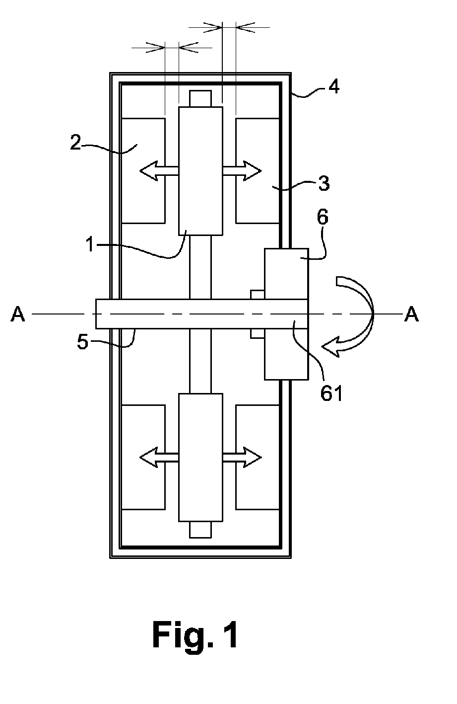
- the figure 1 schematically represents an example of an electric machine with a disc structure with a double stator, called the machine MFADS (Machine Double Axis Axial Flux), comprising a central rotor disc 1 and a stator consisting of two discs 2 and 3.
- Each stator disc 2, 3 is held by conventional mechanical means on a carcass 4. They have a central portion recessed and are centered on the axis AA of the machine.
- the rotor disc 1, disposed between the two stator disks 2, 3, is mounted integral with a drive shaft 5, which passes through the recessed central portion of the stator and whose axis coincides with the axis AA of the machine.
- the rotor drive shaft 5 is rotatably mounted about the axis AA, via a bearing 6 preferably consisting of a bearing.
- the problem that arises then is to adjust the value of the air gap, in order to minimize the axial imbalance.
- the drag torque of the rotor otherwise known as the resistive torque, which results in particular from the friction between the external surface of the drive shaft and the friction surface 61 of the bore of the bearing or bearing 6, when the rotor 1 is rotated and, by iterating, according to several iterations of axial displacement of the rotor 1, until a torque value is obtained acceptable residual, which is representative of the symmetrical character of the gap, that is to say of an air gap configuration where the value of the left air gap e1 is equal to or substantially equal to that of the right air gap e2 .
- the method consists in finding, once the assembled machine, the best axial position for the rotor 1 along the axis AA of the machine, that is to say the axial position able to optimize the torque of drag and therefore, ensuring the desired adjustment of the gap remaining between the inner face of the stator disks 2, 3 and the outer faces of the rotor disk 1.
- the process steps will be described in more detail with reference to the flow chart of the figure 2 .
- the drive shaft 5 When assembling the machine, the drive shaft 5 must be able to translate freely along its axis with respect to the carcass 4 to allow axial displacement of the rotor 1.
- the axial displacement of the rotor 1 is preferably driven by a linear motor, able to cause the axial displacement of the rotor 1 in both directions along the axis AA of the machine from an initial axial position of assembly.
- step E0 once the machine is assembled, the rotor 1 is rotated in its initial axial position of assembly, then the resistive torque of the rotor 1 is measured in this initial axial position of assembly by means of means known per se and it is verified during a test step E1 if the measured value of the resistive torque is lower than a predetermined target torque value, corresponding to an acceptable resistive torque value, representative of a suitable air gap configuration. to minimize the axial imbalance. If the verification is positive, during a step E2 of clamping the rotor 1, the assembly of the machine is completed by performing an axial blocking of the rotor 1 by means of a mechanical interface piece adapted to fix the rotor 1 in the initial axial position of assembly.
- step E3 More precisely, starting from the initial axial position of assembly, it is proceeded by iterations during which a succession of rotor resistant torque measurements corresponding to different successive axial positions of the rotor resulting from the axial displacement of the rotor according to a cycle will be carried out. predetermined measurement.
- step E4 at each iteration Ni of axial displacement of the rotor, an axial displacement of the rotor is generated, so as to place the rotor in a predetermined axial position Xi, the rotor is rotated in several revolutions this predetermined axial position Xi and the value of the resistive torque Ci resulting from the rotation of the rotor is measured. This value of resistive torque Ci corresponding to said predetermined axial position Xi is then stored. This process is repeated at each iteration of axial displacement of the rotor according to a predetermined measuring cycle.
- the figure 3 presents an example of a measurement cycle providing the different axial positions of the rotor at which the resistive torque measurements can be made.
- the rotor is displaced axially by a fixed pitch of 0.1 mm, for example, this displacement being able to take place in one direction as in the other since the initial axial position of assembly.
- the value of the pitch will ideally be determined in correspondence with the needs of the machine to be assembled.
- the measuring cycle thus makes it possible to measure the resistive torque of the rotor over an axial displacement range of 0.3 mm around the initial axial position of assembly in steps of 0.1 mm axially.
- the different axial positions of the rotor for which the resistant torque measurements must be made can be established by controlling the axial displacement of the rotor according to a sinusoidal periodic signal as illustrated in FIG. figure 4 .
- a step E5 the axial position Xi is selected, minimizing the resistive torque Ci and consequently the axial imbalance.
- the axial position thus selected thus provides an optimal adjustment of the air gap value of the machine.
- a step E6 of setting the rotor at the selected position Xi is implemented, before the assembly of the machine can be completed.
- This staggering step can be performed by means of shims or, alternatively, by means of clamping nuts.
- wedges the thickness of which corresponds to the value of the axial displacement iteration pitch, are introduced on one of the faces of the rotor, and then the end is terminated. assembly as described with reference to step E2, by performing the axial blocking of the rotor on the mechanical interface piece intended for this purpose.
- This last axial blocking step E2 is preferably preceded by the test step E1 consisting of checking that the stored torque value for the axial position selected at the end of the iterative process is well below the predetermined target torque value.
Landscapes
- Engineering & Computer Science (AREA)
- Manufacturing & Machinery (AREA)
- Power Engineering (AREA)
- Manufacture Of Motors, Generators (AREA)
Abstract
L'invention concerne un procédé d'assemblage d'une machine électrique à structure discoïde, comportant au moins un disque rotor (1) et stator (2, 3) disposés coaxialement et formant au moins un entrefer (e1, e2). Selon l'invention, une étape d'ajustement dudit entrefer comprend une opération itérative (E3) consistant à chaque itération :
- à déplacer axialement ledit disque rotor (1) dans une position axiale prédéterminée (Xi),
- à entraîner en rotation ledit disque rotor (1) dans ladite position axiale,
- à mesurer une valeur de couple résistant (Ci) résultant de la mise en rotation dudit disque rotor (1) dans ladite position axiale (Xi), et
- à mémoriser ladite valeur de couple (Ci) pour ladite position axiale (xi), ladite étape d'ajustement comprenant une étape (E5) de sélection de la position axiale minimisant le couple résistant et une étape (E2) de blocage axial dudit disque rotor dans ladite position axiale sélectionnée.
moving axially said rotor disc (1) in a predetermined axial position (Xi),
to rotate said rotor disk (1) in said axial position,
- measuring a resistive torque value (Ci) resulting from the rotation of said rotor disk (1) in said axial position (Xi), and
storing said torque value (Ci) for said axial position (xi), said adjusting step comprising a step (E5) for selecting the axial position minimizing the resisting torque and a step (E2) for axially locking said disc rotor in said selected axial position.
Description
La présente invention concerne le domaine des machines électriques à flux axial, également nommées machines électriques à structure discoïde. Elle concerne plus particulièrement un procédé d'assemblage d'une telle machine comportant au moins un disque rotor et stator disposés coaxialement et formant au moins un entrefer, du type comportant une étape d'ajustement dudit au moins un entrefer.The present invention relates to the field of axial flow electric machines, also called discoidal structure electrical machines. It relates more particularly to a method of assembling such a machine comprising at least one rotor disk and stator arranged coaxially and forming at least one gap, of the type comprising a step of adjusting said at least one gap.
De façon générale, les machines électriques de structure discoïde comprennent au moins un stator en forme de disque maintenu sur une carcasse et dont la partie centrale est généralement évidée, ainsi qu'un rotor également en forme de disque, monté sur un arbre dont l'axe de rotation coïncide avec l'axe du disque stator. Les avantages particuliers liés à ces machines sont notamment la compacité associée à un rendement élevé.In general, the electrical machines of discoid structure comprise at least one disc-shaped stator held on a carcass and whose central part is generally hollow, and a rotor also disc-shaped, mounted on a shaft of which axis of rotation coincides with the axis of the stator disk. The particular advantages of these machines include compactness and high efficiency.
Dans la littérature, différentes topologies de machines à flux axial sont connues. On connaît ainsi les machines discoïdes simple face comprenant un disque rotor monté en rotation sur l'arbre de la machine et un disque stator relié à la carcasse et centré sur l'axe de l'arbre. On connaît également les machines discoïdes double faces, comprenant un disque stator, placé entre deux disques rotor, les bobinages des disques rotor et stator étant placés sur des faces en regard, le disque stator étant équipé d'enroulement sur ses deux faces (machines discoïdes dites à stator intérieur). Cette dernière topologie de machines regroupe également les machines électriques à structure discoïde, dans lesquelles un disque rotor est placé entre deux disques stator, les bobinages des disques rotor et stator étant placés sur des faces en regard, le disque rotor étant équipé d'aimants ou d'enroulement sur ses deux faces (machines discoïdes dites à rotor intérieur).In the literature, different topologies of axial flow machines are known. Thus, single-sided disc machines are known comprising a rotor disk rotatably mounted on the shaft of the machine and a stator disk connected to the carcass and centered on the axis of the shaft. Double disc disc machines, comprising a stator disc, placed between two rotor disks, the windings of the rotor and stator disks being placed on facing faces, the stator disk being equipped with winding on its two faces (disc machines say to inner stator). This last machine topology also groups electrical machines with discoid structure, in which a rotor disk is placed between two stator disks, the rotor and stator rotor windings being placed on facing faces, the rotor disk being equipped with magnets or winding on both sides (discoid machines called internal rotor).
Egalement, toutes les machines discoïdes, qu'elles soient à simple face ou double face, peuvent être comme dans le cas des machines à flux radial, à stator encoché ou lisse ou bien encore de type présentant une saillance magnétique ou pas.Also, all discoid machines, whether single-sided or double-sided, can be as in the case of radial flow machines, notched or smooth stator or even type having magnetic saliency or not.
Quelle que soit la topologie de la machine électrique de type discoïde, un réglage précis de l'entrefer stator-rotor est nécessaire, de la phase de calcul et conception jusqu'à la phase d'assemblage de la machine, dans la mesure où cette valeur d'entrefer a une répercussion directe sur les performances de la machine.Whatever the topology of the discoid type electric machine, a precise adjustment of the stator-rotor gap is necessary, from the calculation and design phase to the assembly phase of the machine, insofar as this gap value has a direct impact on the machine's performance.
Dans le cas d'une machine comportant au moins trois disques rotor et stator disposés coaxialement, par exemple telle que les machines à double stator, les faces des disques stator et rotor sont séparées par deux entrefers, respectivement gauche et droit et, au moment du montage, les dimensions de ces entrefers sont prévues approximativement égales. En effet, un déséquilibre entre les entrefers génère un effort axial asymétrique, ayant un impact défavorable sur le rendement de la machine d'un point de vue strictement électromagnétique, mais aussi sur les contraintes mécaniques s'exerçant sur les éléments de guidage (paliers, roulements à billes, etc.) et génère en outre un couple de traînée nuisible au rendement global de la machine. Or, dans ce type de machine, le rotor peut présenter des décalages axiaux par rapport au stator, en raison des tolérances mécaniques d'usinage et de montage des différents éléments. On constate également que les dimensions de l'entrefer peuvent varier, du fait des dilatations thermiques des matériaux et des efforts mécaniques. Ainsi, du fait des variations dimensionnelles apparaissant à l'intérieur de la machine discoïde, les forces engendrées au niveau de chaque entrefer ne s'annulent pas en pratique et, pendant le fonctionnement de la machine, des efforts axiaux importants apparaissent sur le rotor et le stator pouvant entraîner la détérioration de la machine.In the case of a machine having at least three rotor disks and stator arranged coaxially, for example such as dual stator machines, the faces of the stator and rotor disks are separated by two gaps, respectively left and right and, at the time of mounting, the dimensions of these air gaps are planned approximately equal. In fact, an imbalance between the air gaps generates an asymmetric axial force, having an adverse impact on the efficiency of the machine from a strictly electromagnetic point of view, but also on the mechanical stresses exerted on the guiding elements (bearings, ball bearings, etc.) and furthermore generates a drag torque detrimental to the overall efficiency of the machine. However, in this type of machine, the rotor may have axial offsets relative to the stator, due to the mechanical tolerances of machining and mounting of the various elements. It is also noted that the dimensions of the gap can vary, due to the thermal expansion of materials and mechanical forces. Thus, because of the dimensional variations occurring inside the discoid machine, the forces generated at each air gap do not cancel out in practice and, during operation of the machine, significant axial forces appear on the rotor and the stator can cause the deterioration of the machine.
On connaît du document de brevet
Cependant, cette méthode d'ajustement de la dimension de l'entrefer n'est pas entièrement satisfaisante, puisqu'elle ne permet pas d'intégrer au circuit de mesure les pertes liées au fonctionnement de la chaîne cinématique globale de la machine, incluant notamment les roulements à billes, les joints potentiellement sources de frottement, etc.However, this method of adjusting the size of the gap is not entirely satisfactory, since it does not make it possible to integrate into the measuring circuit the losses related to the operation of the overall kinematic chain of the machine, including in particular ball bearings, seals potentially sources of friction, etc.
Dans ce contexte, la présente invention a pour but de pallier ces inconvénients en proposant un procédé d'assemblage d'une machine électrique à structure discoïde permettant de réaliser un ajustement plus précis de l'entrefer.In this context, the present invention aims to overcome these disadvantages by proposing a method of assembling an electric machine discoid structure to achieve a more precise adjustment of the air gap.
A cette fin, la présente invention propose un procédé d'assemblage d'une machine électrique à structure discoïde, comportant au moins un disque rotor et stator disposés coaxialement et formant au moins un entrefer, ledit procédé comprenant une étape d'ajustement dudit au moins un entrefer, caractérisé en ce que ladite étape d'ajustement comprend une opération itérative consistant à chaque itération :
- à déplacer axialement ledit disque rotor dans une position axiale prédéterminée,
- à entraîner en rotation ledit disque rotor dans ladite position axiale,
- à mesurer une valeur de couple résistant résultant de la mise en rotation dudit disque rotor dans ladite position axiale, et
- à mémoriser ladite valeur de couple résistant pour ladite position axiale,
- axially displacing said rotor disk in a predetermined axial position,
- rotating said rotor disk in said axial position,
- measuring a resistive torque value resulting from the rotation of said rotor disk in said axial position, and
- storing said resistance torque value for said axial position,
Ce procédé consistant à réaliser des mesures de couple résistant résultant de l'entraînement en rotation du rotor à chaque itération de déplacement axial du rotor, permet avantageusement de tenir compte de toute la chaîne cinématique pour la mise au point de l'entrefer. Ainsi, cette solution est basée sur un mode de fonctionnement « pièces tournantes » et offre donc une plus grande précision dans l'ajustement de l'entrefer, puisque toutes les pertes sont intégrées dans la mesure. Au final, le type de mesure proposée par la présente invention permet d'avoir une image fonctionnelle de l'entrefer par la valeur du couple résistant du rotor et ainsi, sans avoir à réaliser des métrologies complexes sur chacun des composants de la machine.This method of making resistive torque measurements resulting from the rotational drive of the rotor at each iteration of axial displacement of the rotor, advantageously allows to take into account the entire kinematic chain for the development of the air gap. Thus, this solution is based on a mode of operation "rotating parts" and thus offers a greater precision in the adjustment of the air gap, since all losses are integrated into the measurement. Finally, the type of measurement proposed by the present invention makes it possible to have a functional image of the gap by the value of the resisting torque of the rotor and thus, without having to perform complex metrology on each of the components of the machine.
Selon d'autres caractéristiques avantageuses du procédé conforme à l'invention, prises isolément ou en combinaison :
- à chaque itération de déplacement axial, on déplace axialement ledit disque rotor selon un pas fixe de déplacement axial prédéterminé ;
- à chaque itération de déplacement axial, on déplace axialement ledit disque rotor suivant un signal périodique sinusoïdal ;
- l'étape de blocage axial est précédée d'une étape préalable de test consistant à vérifier que la valeur de couple pour ladite position axiale sélectionnée est inférieure à une valeur cible prédéterminée du couple ;
- lorsque la position axiale minimisant le couple résistant est sélectionnée, ledit disque rotor est calé dans ladite position sélectionnée au moyen d'une cale d'épaisseur correspondant à la valeur du déplacement axial auquel ledit couple a été mesuré ;
- lorsque la position axiale minimisant le couple résistant est sélectionnée, ledit disque rotor est calé dans ladite position sélectionnée au moyen d'écrous de serrage asservis en position dans ladite position sélectionnée.
- at each axial displacement iteration, said rotor disk is displaced axially in a fixed step of predetermined axial displacement;
- at each axial displacement iteration, said rotor disk is displaced axially according to a sinusoidal periodic signal;
- the axial blocking step is preceded by a prior test step of verifying that the torque value for said selected axial position is less than a predetermined target value of the torque;
- when the axial position minimizing the resistive torque is selected, said rotor disk is keyed in said selected position by means of a shim corresponding to the value of the axial displacement at which said torque was measured;
- when the axial position minimizing the resisting torque is selected, said rotor disk is keyed in said selected position by means of clamping nuts slaved into position in said selected position.
D'autres particularités et avantages de l'invention ressortiront à la lecture de la description faite ci-après d'un mode de réalisation particulier de l'invention, donné à titre indicatif mais non limitatif, en référence aux dessins annexés sur lesquels :
- la
Figure 1 est une vue schématique d'un exemple d'ensemble rotor/stator d'une machine discoïde sur laquelle peut être appliqué le procédé d'assemblage conforme à la présente invention pour la mise au point de l'entrefer; - la
Figure 2 est un organigramme du procédé d'assemblage conforme à la présente invention; - la
Figure 3 illustre un premier exemple de cycle de mesure fournissant les positions axiales du rotor où les mesures de couple résistant peuvent être effectuées ; - la
Figure 4 illustre un deuxième exemple de cycle de mesure fournissant les positions axiales du rotor où les mesures de couple résistant peuvent être effectuées.
- the
Figure 1 is a schematic view of an exemplary rotor / stator assembly of a disc machine on which the assembly method according to the present invention can be applied for the development of the gap; - the
Figure 2 is a flowchart of the assembly method according to the present invention; - the
Figure 3 illustrates a first example of a measurement cycle providing the axial positions of the rotor where the resistive torque measurements can be made; - the
Figure 4 illustrates a second example of a measurement cycle providing the axial positions of the rotor where the resistive torque measurements can be made.
La
Entre la face interne des disques stator 2, 3 et les faces externes du disque rotor 1, il subsiste un entrefer, respectivement e1 et e2. Ces deux entrefers sont théoriquement de même valeur de part et d'autre du disque rotor 1. Cependant, en raison des écarts de tolérance de fabrication et du process d'assemblage, la valeur des entrefers est en pratique différente.Between the inner face of the
La problématique qui se pose alors est d'ajuster la valeur de l'entrefer, afin de minimiser le déséquilibre axial. Selon l'invention, une fois la machine assemblée, on se propose de mesurer le couple de traînée du rotor 1, dit autrement le couple résistant, qui résulte en particulier du frottement entre la surface externe de l'arbre 5 d'entraînement et la surface de friction 61 de l'alésage du palier ou roulement 6, lorsque le rotor 1 est entraîné en rotation et ce, en procédant par itération, selon plusieurs itérations de déplacement axial du rotor 1, jusqu'à obtention d'une valeur de couple résiduel acceptable, qui soit représentative du caractère symétrique de l'entrefer, c'est-à-dire d'une configuration d'entrefer où la valeur de l'entrefer gauche e1 est égale ou sensiblement égale à celle de l'entrefer droit e2. En effet, lorsque l'on s'écarte de cette configuration, les efforts axiaux asymétriques, qui sont alors générés de part et d'autre du rotor 1, impactent le chargement mécanique sur les éléments de guidage, en particulier le palier ou roulement 6, générant le couple de traînée du rotor. Aussi, il y a un lien direct entre l'existence et la valeur du couple de trainée du rotor et la configuration d'entrefer, que le procédé de l'invention se propose d'exploiter.The problem that arises then is to adjust the value of the air gap, in order to minimize the axial imbalance. According to the invention, once the machine is assembled, it is proposed to measure the drag torque of the
Pour ce faire, le procédé consiste à rechercher, une fois la machine assemblée, la meilleure position axiale pour le rotor 1 le long de l'axe A-A de la machine, c'est-à-dire la position axiale apte à optimiser le couple de traînée et partant, assurant l'ajustement souhaité de l'entrefer subsistant entre la face interne des disques stator 2, 3 et les faces externes du disque rotor 1. Les étapes du procédé vont être décrites plus en détail en référence à l'organigramme de la
Lors de l'assemblage de la machine, l'arbre 5 d'entraînement doit pouvoir translater librement le long de son axe par rapport à la carcasse 4 pour permettre le déplacement axial du rotor 1. En outre, le déplacement axial du rotor 1 est préférentiellement piloté par un moteur linéaire, apte à provoquer le déplacement axial du rotor 1 dans les deux directions le long de l'axe A-A de la machine depuis une position axiale initiale d'assemblage.When assembling the machine, the
Initialement, lors d'une étape E0, une fois la machine assemblée, le rotor 1 est entraîné en rotation dans sa position axiale initiale d'assemblage, puis on mesure le couple résistant du rotor 1 dans cette position axiale initiale d'assemblage par des moyens connus en soi et on vérifie lors d'une étape de test E1 si la valeur mesurée du couple résistant est inférieure à une valeur cible prédéterminée de couple, correspondant à une valeur de couple résistant acceptable, représentative d'une configuration d'entrefer apte à minimiser le déséquilibre axial. Si la vérification est positive, lors d'une étape E2 de bridage du rotor 1, l'assemblage de la machine est terminé en réalisant un blocage axial du rotor 1 au moyen d'une pièce interface mécanique apte à fixer le rotor 1 dans la position axiale initiale d'assemblage.Initially, during a step E0, once the machine is assembled, the
Par contre, si la vérification s'avère être négative, on déclenche une opération itérative à l'étape E3. Plus précisément, à partir de la position axiale initiale d'assemblage, on procède par itérations au cours desquelles on va effectuer une succession de mesures de couple résistant du rotor correspondant à différentes positions axiales successives du rotor résultant du déplacement axial du rotor suivant un cycle de mesure prédéterminé. Ainsi, lors d'une étape E4, à chaque itération Ni de déplacement axial du rotor, on génère un déplacement axial du rotor, de sorte à placer le rotor dans une position axiale prédéterminée Xi, on entraîne le rotor en rotation sur plusieurs tours dans cette position axiale prédéterminée Xi et on mesure la valeur du couple résistant Ci résultant de la mise en rotation du rotor. Cette valeur de couple résistant Ci correspondant à ladite position axiale prédéterminée Xi est alors mémorisée. On répète ce processus à chaque itération de déplacement axial du rotor suivant un cycle de mesure prédéterminé.On the other hand, if the verification proves to be negative, it triggers an iterative operation in step E3. More precisely, starting from the initial axial position of assembly, it is proceeded by iterations during which a succession of rotor resistant torque measurements corresponding to different successive axial positions of the rotor resulting from the axial displacement of the rotor according to a cycle will be carried out. predetermined measurement. Thus, during a step E4, at each iteration Ni of axial displacement of the rotor, an axial displacement of the rotor is generated, so as to place the rotor in a predetermined axial position Xi, the rotor is rotated in several revolutions this predetermined axial position Xi and the value of the resistive torque Ci resulting from the rotation of the rotor is measured. This value of resistive torque Ci corresponding to said predetermined axial position Xi is then stored. This process is repeated at each iteration of axial displacement of the rotor according to a predetermined measuring cycle.
La
En variante, les différentes positions axiales du rotor pour lesquelles les mesures de couple résistant doivent être effectuées, peuvent être établies en commandant le déplacement axial du rotor suivant un signal périodique sinusoïdal tel qu'illustré à la
Ensuite, au terme de ce processus itératif, lors d'une étape E5, on sélectionne la position axiale Xi minimisant le couple résistant Ci et par conséquent, le déséquilibre axial. La position axiale ainsi sélectionnée procure donc un ajustement optimal de la valeur d'entrefer de la machine. Lorsque la sélection de la position Xi est effectuée, une étape E6 de calage du rotor à la position sélectionnée Xi est mise en oeuvre, avant de pouvoir terminer l'assemblage de la machine. Cette étape de calage pourra être réalisée au moyen de cales d'épaisseur ou, en variante, à l'aide d'écrous de serrage.Then, at the end of this iterative process, during a step E5, the axial position Xi is selected, minimizing the resistive torque Ci and consequently the axial imbalance. The axial position thus selected thus provides an optimal adjustment of the air gap value of the machine. When the selection of the position Xi is carried out, a step E6 of setting the rotor at the selected position Xi is implemented, before the assembly of the machine can be completed. This staggering step can be performed by means of shims or, alternatively, by means of clamping nuts.
Ainsi, une fois la sélection effectuée, selon cette étape de calage, on introduit des cales, dont l'épaisseur correspond à la valeur du pas d'itération de déplacement axial, sur l'une des faces du rotor, puis on termine l'assemblage comme décrit en référence à l'étape E2, en réalisant le blocage axial du rotor sur la pièce interface mécanique destinée à cet effet.Thus, once the selection has been made, according to this staggering step, wedges, the thickness of which corresponds to the value of the axial displacement iteration pitch, are introduced on one of the faces of the rotor, and then the end is terminated. assembly as described with reference to step E2, by performing the axial blocking of the rotor on the mechanical interface piece intended for this purpose.
Cette dernière étape E2 de blocage axial est préférentiellement précédée de l'étape E1 de test consistant à vérifier que la valeur de couple mémorisée pour la position axiale sélectionnée au terme du processus itératif est bien inférieure à la valeur cible de couple prédéterminée.This last axial blocking step E2 is preferably preceded by the test step E1 consisting of checking that the stored torque value for the axial position selected at the end of the iterative process is well below the predetermined target torque value.
Bien que la description qui précède concerne l'ajustement de l'entrefer pour la machine à flux axial à double stator, il convient de noter que la solution décrite ne se limite pas à ce type de machine spécifiquement, mais peut être utilisée plus largement pour la mise au point de l'entrefer dans n'importe quel type de machine à flux axial, en particulier à simple face ou double face et cela, quel que soit la technologie de la machine : asynchrone à flux axial, à aimant à flux axial, à rotor bobiné à flux axial, à courant continu à flux axial, à reluctance variable à flux axial.Although the foregoing description relates to air gap adjustment for the double stator axial flow machine, it should be noted that the described solution is not limited to this type of machine specifically, but can be used more widely for the development of the air gap in any type of axial flow machine, in particular single-sided or double-sided and this, whatever the technology of the machine: asynchronous axial flow, axial flux magnet axial-flow, axial-flow, axial-flow, axial-flow, variable-flux-coiled rotor.
Claims (6)
Applications Claiming Priority (1)
| Application Number | Priority Date | Filing Date | Title |
|---|---|---|---|
| FR1355184A FR3006828B1 (en) | 2013-06-05 | 2013-06-05 | METHOD FOR ASSEMBLING AN AXIAL FLUX ELECTRIC MACHINE |
Publications (2)
| Publication Number | Publication Date |
|---|---|
| EP2822158A2 true EP2822158A2 (en) | 2015-01-07 |
| EP2822158A3 EP2822158A3 (en) | 2016-01-06 |
Family
ID=48874383
Family Applications (1)
| Application Number | Title | Priority Date | Filing Date |
|---|---|---|---|
| EP14305789.1A Withdrawn EP2822158A3 (en) | 2013-06-05 | 2014-05-27 | Method for assembling an electrical machine with axial flow |
Country Status (2)
| Country | Link |
|---|---|
| EP (1) | EP2822158A3 (en) |
| FR (1) | FR3006828B1 (en) |
Cited By (1)
| Publication number | Priority date | Publication date | Assignee | Title |
|---|---|---|---|---|
| CN111307073A (en) * | 2020-03-16 | 2020-06-19 | 湖南米艾西测控技术有限公司 | Device for measuring coaxiality deviation of rotary transformer stator and rotor |
Citations (1)
| Publication number | Priority date | Publication date | Assignee | Title |
|---|---|---|---|---|
| WO2006005796A1 (en) | 2004-07-09 | 2006-01-19 | Kone Corporation | Method and apparatus for the assembly of an axial-flux permanent-magnet synchronous machine |
Family Cites Families (2)
| Publication number | Priority date | Publication date | Assignee | Title |
|---|---|---|---|---|
| DE3234274A1 (en) * | 1982-09-13 | 1984-04-05 | Christian Ing.(grad.) 1000 Berlin Herrmann | Induction motor with an asynchronously running disc rotor |
| DE102007037842A1 (en) * | 2006-09-21 | 2008-04-03 | Luk Lamellen Und Kupplungsbau Beteiligungs Kg | Electrical machine i.e. electronically commutated motor, for use as drive for operating e.g. clutch, has stator parts connected with mounting plate in adjustable manner by adjusting device, such that gap width of air gap is adjustable |
-
2013
- 2013-06-05 FR FR1355184A patent/FR3006828B1/en not_active Expired - Fee Related
-
2014
- 2014-05-27 EP EP14305789.1A patent/EP2822158A3/en not_active Withdrawn
Patent Citations (1)
| Publication number | Priority date | Publication date | Assignee | Title |
|---|---|---|---|---|
| WO2006005796A1 (en) | 2004-07-09 | 2006-01-19 | Kone Corporation | Method and apparatus for the assembly of an axial-flux permanent-magnet synchronous machine |
Cited By (1)
| Publication number | Priority date | Publication date | Assignee | Title |
|---|---|---|---|---|
| CN111307073A (en) * | 2020-03-16 | 2020-06-19 | 湖南米艾西测控技术有限公司 | Device for measuring coaxiality deviation of rotary transformer stator and rotor |
Also Published As
| Publication number | Publication date |
|---|---|
| FR3006828B1 (en) | 2015-06-26 |
| FR3006828A1 (en) | 2014-12-12 |
| EP2822158A3 (en) | 2016-01-06 |
Similar Documents
| Publication | Publication Date | Title |
|---|---|---|
| EP2032294B1 (en) | Ring-rolling bearing with axial displacement and shaping tooling equipped with such a bearing | |
| EP2160819B1 (en) | Shaft supporting system for an electric motor, electric motor and assembly method | |
| EP2153076B1 (en) | Indexation instrumented bearing device | |
| EP1774272A1 (en) | Position sensor which is intended, in particular, for measuring steering column torsion | |
| EP2332232B1 (en) | Stator for rotary electric machine and method for making same | |
| EP0544575B1 (en) | Variable reluctance absolute angular position sensor | |
| EP2488830A2 (en) | Magnetic sensor for determining the position and orientation of a target | |
| EP1196787B1 (en) | Instrumented bearing | |
| EP3651345B1 (en) | Method for reducing the detent torque produced by brushless type electric motors used simultaneously | |
| EP2822158A2 (en) | Method for assembling an electrical machine with axial flow | |
| EP4367479A1 (en) | Brake lining wear sensor | |
| EP3648314B1 (en) | Brushless direct current electric motor with reduced detent torque and method for manufacturing same | |
| EP2854259A1 (en) | Rotor shaft of an electric machine with at least one fin for creating an air flow inside the shaft, rotor comprising such a shaft and electric machine comprising such a rotor | |
| EP3300224A1 (en) | Brushless direct current electric motor for a motor vehicle wiper system | |
| WO2015097396A1 (en) | Turbine engine assembly for measuring the vibrations to which a rotating blade is subjected | |
| EP3167543B1 (en) | Method for generating control signals for managing the operation of a synchronous motor, control device and actuator | |
| EP4305385A1 (en) | Magnet sensor and ferromagnetic poles | |
| FR3047776B1 (en) | TURBOMACHINE AND METHOD OF MOUNTING | |
| FR3100942A1 (en) | Flat sheet for the manufacture of a rotating electric machine stator | |
| WO2014161911A1 (en) | Electric motor having a low short-circuit torque, drive device with a plurality of motors and method for producing such a motor | |
| EP1953898B1 (en) | Slewing ring with built-in rotation motor | |
| FR3002191A3 (en) | "MOTOR POWERTRAIN COMPRISING AN ELECTRIC MOTOR IN WHICH THE ROTOR IS CARRIED ONLY BY THE GEARBOX SHAFT" | |
| FR3037734A1 (en) | ROTOR WITH STACKED SHEETS. | |
| EP4379324A1 (en) | Method for adjusting a measuring device with at least one position sensor | |
| FR3080679A1 (en) | DEVICE FOR DETECTING THE ANGULAR POSITION OF A ROTOR OF A ROTATING ELECTRIC MACHINE |
Legal Events
| Date | Code | Title | Description |
|---|---|---|---|
| PUAI | Public reference made under article 153(3) epc to a published international application that has entered the european phase |
Free format text: ORIGINAL CODE: 0009012 |
|
| 17P | Request for examination filed |
Effective date: 20140527 |
|
| AK | Designated contracting states |
Kind code of ref document: A2 Designated state(s): AL AT BE BG CH CY CZ DE DK EE ES FI FR GB GR HR HU IE IS IT LI LT LU LV MC MK MT NL NO PL PT RO RS SE SI SK SM TR |
|
| AX | Request for extension of the european patent |
Extension state: BA ME |
|
| PUAL | Search report despatched |
Free format text: ORIGINAL CODE: 0009013 |
|
| AK | Designated contracting states |
Kind code of ref document: A3 Designated state(s): AL AT BE BG CH CY CZ DE DK EE ES FI FR GB GR HR HU IE IS IT LI LT LU LV MC MK MT NL NO PL PT RO RS SE SI SK SM TR |
|
| AX | Request for extension of the european patent |
Extension state: BA ME |
|
| RIC1 | Information provided on ipc code assigned before grant |
Ipc: H02K 15/16 20060101AFI20151130BHEP |
|
| STAA | Information on the status of an ep patent application or granted ep patent |
Free format text: STATUS: THE APPLICATION IS DEEMED TO BE WITHDRAWN |
|
| 18D | Application deemed to be withdrawn |
Effective date: 20160707 |