EP2822406B1 - Procédé, dispositif de dosage et soupape de dosage, pour le dosage aseptique d'un additif liquide, dans un écoulement forcé d'un produit de base - Google Patents
Procédé, dispositif de dosage et soupape de dosage, pour le dosage aseptique d'un additif liquide, dans un écoulement forcé d'un produit de base Download PDFInfo
- Publication number
- EP2822406B1 EP2822406B1 EP12712927.8A EP12712927A EP2822406B1 EP 2822406 B1 EP2822406 B1 EP 2822406B1 EP 12712927 A EP12712927 A EP 12712927A EP 2822406 B1 EP2822406 B1 EP 2822406B1
- Authority
- EP
- European Patent Office
- Prior art keywords
- chamber
- metering
- additive
- end section
- terminal part
- Prior art date
- Legal status (The legal status is an assumption and is not a legal conclusion. Google has not performed a legal analysis and makes no representation as to the accuracy of the status listed.)
- Active
Links
Images




Classifications
-
- A—HUMAN NECESSITIES
- A23—FOODS OR FOODSTUFFS; TREATMENT THEREOF, NOT COVERED BY OTHER CLASSES
- A23B—PRESERVATION OF FOODS, FOODSTUFFS OR NON-ALCOHOLIC BEVERAGES; CHEMICAL RIPENING OF FRUIT OR VEGETABLES
- A23B2/00—Preservation of foods or foodstuffs, in general
- A23B2/001—Details of apparatus, e.g. pressure feed valves or for transport, or loading or unloading manipulation
-
- A—HUMAN NECESSITIES
- A23—FOODS OR FOODSTUFFS; TREATMENT THEREOF, NOT COVERED BY OTHER CLASSES
- A23B—PRESERVATION OF FOODS, FOODSTUFFS OR NON-ALCOHOLIC BEVERAGES; CHEMICAL RIPENING OF FRUIT OR VEGETABLES
- A23B2/00—Preservation of foods or foodstuffs, in general
- A23B2/40—Preservation of foods or foodstuffs, in general by heating loose unpacked materials
- A23B2/42—Preservation of foods or foodstuffs, in general by heating loose unpacked materials while they are progressively transported through the apparatus
- A23B2/46—Preservation of foods or foodstuffs, in general by heating loose unpacked materials while they are progressively transported through the apparatus with transport through tubes
-
- A—HUMAN NECESSITIES
- A61—MEDICAL OR VETERINARY SCIENCE; HYGIENE
- A61L—METHODS OR APPARATUS FOR STERILISING MATERIALS OR OBJECTS IN GENERAL; DISINFECTION, STERILISATION OR DEODORISATION OF AIR; CHEMICAL ASPECTS OF BANDAGES, DRESSINGS, ABSORBENT PADS OR SURGICAL ARTICLES; MATERIALS FOR BANDAGES, DRESSINGS, ABSORBENT PADS OR SURGICAL ARTICLES
- A61L2/00—Disinfection or sterilisation of materials or objects, in general; Accessories therefor
- A61L2/02—Disinfection or sterilisation of materials or objects, in general; Accessories therefor using physical processes
- A61L2/04—Heat
- A61L2/06—Hot gas
- A61L2/07—Steam
-
- G—PHYSICS
- G01—MEASURING; TESTING
- G01F—MEASURING VOLUME, VOLUME FLOW, MASS FLOW OR LIQUID LEVEL; METERING BY VOLUME
- G01F11/00—Apparatus requiring external operation adapted at each repeated and identical operation to measure and separate a predetermined volume of fluid or fluent solid material from a supply or container, without regard to weight, and to deliver it
- G01F11/28—Apparatus requiring external operation adapted at each repeated and identical operation to measure and separate a predetermined volume of fluid or fluent solid material from a supply or container, without regard to weight, and to deliver it with stationary measuring chambers having constant volume during measurement
- G01F11/30—Apparatus requiring external operation adapted at each repeated and identical operation to measure and separate a predetermined volume of fluid or fluent solid material from a supply or container, without regard to weight, and to deliver it with stationary measuring chambers having constant volume during measurement with supply and discharge valves of the lift or plug-lift type
- G01F11/32—Apparatus requiring external operation adapted at each repeated and identical operation to measure and separate a predetermined volume of fluid or fluent solid material from a supply or container, without regard to weight, and to deliver it with stationary measuring chambers having constant volume during measurement with supply and discharge valves of the lift or plug-lift type for liquid or semiliquid
-
- A—HUMAN NECESSITIES
- A23—FOODS OR FOODSTUFFS; TREATMENT THEREOF, NOT COVERED BY OTHER CLASSES
- A23V—INDEXING SCHEME RELATING TO FOODS, FOODSTUFFS OR NON-ALCOHOLIC BEVERAGES AND LACTIC OR PROPIONIC ACID BACTERIA USED IN FOODSTUFFS OR FOOD PREPARATION
- A23V2002/00—Food compositions, function of food ingredients or processes for food or foodstuffs
Definitions
- the invention relates to a method for the aseptic dosing of a liquid additive, in particular an additive produced and stored under aseptic conditions, in a forced flow of a base product which is also provided under aseptic conditions, wherein the additive under aseptic conditions by means of a withdrawal line from a storage container taken and over an end portion of the extraction line the base product, which flows through a product space, is supplied, and a metering device for carrying out the method and a metering valve for the metering device.
- Liquid aseptic additives of the aforementioned kind such as enzymes, flavors, colors, lipids, probiotic bacteria and other nutrients, are dosed into a foodstuff acting as an aseptic base product of the aforementioned type in order to provide it with special properties. Since these additives can be sensitive to heat, the supply of these additives into the base product takes place immediately before it is filled and after its heat treatment to kill unwanted germs, for example an ultra-high-temperature treatment (UHT heat treatment), and preferably within the framework of a so-called. line dosing.
- UHT heat treatment ultra-high-temperature treatment
- DE10337057 discloses a method for the cold aseptic filling of beverages and US 2002/172745 relates to a system for in-line loading of beverages.
- lactose-reduced or lactose-free products A widespread application, in which an enzyme is used as an additive, is the production of lactose-reduced or lactose-free products.
- lactase is used for the enzymatic cleavage of lactose. consumed These products are mainly used by people who suffer from a deficiency of ⁇ -galactosidase in the digestive tract.
- lactose-reduced milk and related substances is the market for calorie-reduced products. Lactose cleavage produces one molecule each of D-glucose and ⁇ -D-galactose [T ⁇ PEL, 2004, p.
- the dosage rate of the subject enzyme ranges from 0.2 to 4 ml of enzyme / liter of base product (200 to 4000 ppm).
- Tetra FlexDos TM flexible aseptic dosing system for liquid additives
- PD 10080 de 2007-02 a metering device is described with the use of a formed in the form of a flexible bag storage container in which an additive the type in question is stockpiled, an aseptic in-line dosage of this liquid additive is made in a base product.
- the ready-to-use 5 or 10-liter bag filled with the sterile additive under aseptic conditions which in turn is accommodated in a bucket-like outer packaging, is suspended in the metering device.
- hose arrangement acting as a removal arrangement is used to transfer the additive from the bag into the base product, which tube is connected to the bag via a special adapter prior to dosing.
- Hose arrangement and bags are prepared and provided separately from each other, they are usually from different manufacturers and are brought together only in the metering device and firmly connected.
- the hose assembly is arranged an injection needle, via which the additive is metered into the base product at an injection point by means of a hose-wheel pump acting on the hose assembly from the outside.
- the injection point is located on a pipe socket of a pipeline in which the base product flows.
- the injection point is designed as a chamber, which then acts as a sterilizing vapor barrier when it is flowed through by suitable sterile vapor.
- Two in-line membranes, the first between the environment and the interior of the chamber, the second between the interior of the chamber and the interior of the pipeline must be pierced by the injection needle before the dosage can begin.
- the known metering device with the bag used for the purpose and the separate hose assembly have disadvantages particularly in the area of the bag and the coupling of the hose assembly and at the point of injection and cause critical treatment steps that can call into question the absolutely required safety of the sterility of the metering process.
- the extraction port on the bag may be exposed to harmful environmental influences and / or possible faulty actions prior to the coupling of the hose assembly, which may affect the sterility of the critical surfaces leading to the metered additive in the course of the coupling process. A sterilization of these critical surfaces after completion of the coupling process is no longer possible. Since the bag and the hose assembly are separated from one another in each case in an outer packaging, resulting solely by this storage and handling situation, a relatively costly and less user-friendly starting position and a not only theoretical possibility for contamination of the critical surfaces with germs.
- the present invention has in particular the task of dosing aseptic small amounts of an additive up to a maximum of 250 ppm directly into the forced flow of an aseptic base product.
- Advantageous embodiments of the method are described in the subclaims.
- a metering device for carrying out the method is the subject of the dependent claim 11.
- Advantageous embodiments of the metering device are specified in the subclaims.
- a metering valve for the proposed metering device is the subject of the dependent claim 19.
- Advantageous embodiments are specified in the subclaims.
- an end-side part of the end section of the extraction line in whatever form it is designed before it temporarily reaches its metering position and readiness, is at least sterilized under scheduled, reproducible and clearly defined and controlled conditions.
- the end-side part can be an integral part of the end section or a part executed separately from the end section, in the latter case this separate part having a controllable outlet opening, for example in the form of a small metering valve.
- the end-side part of the end portion is still outside the product space in which the dosage takes place, and there are areas of the end-side part of the end portion, in its later dosing at the penetration point within a necessary there sealant and, based on the product space above Be on the side facing away from the product space side of the sealant, included in the sterilization.
- Only after at least this sterilization which is preferably carried out temperature-controlled, reaches the end-side part of the end portion in its metering position, wherein still no connection to the product space is made and this position is referred to as a waiting position.
- the end-side part of the end portion is sealed at its penetration point by means of the previously at least sterilized sealing means.
- the sterilization is carried out in a conventional manner expediently with sterile steam (sterile steam) and the cooling is expediently carried out with sterile air, wherein according to a further proposal, this temperature treatment is carried out in a controlled manner by the sterilization and the cooling carried out temperature-controlled. Only when a predetermined temperature limit value is reached at the temperature measuring point, which, viewed in the flow direction of the respective fluid, is arranged downstream of the end-side part of the extraction line to be treated, is the respective temperature treatment terminated.
- the sterilization is carried out in a targeted manner at a temperature above 125 ° C and the cooling is carried out at a temperature below 50 ° C.
- a rinse of the initial room with sterile condensate (sterile condensate) is carried out below a temperature of 50 ° C.
- This rinsing may be carried out after the treatment step (b) or (c), after the treatment step (c), the initial space is first to be prepared before the rinsing is initiated.
- the additive is metered proportionate to the flowing base product.
- the necessary dosing accuracy is achieved when the transport of the additive in the extraction line and possibly also the removal from the storage container in a conventional manner forcibly done.
- the metering device for carrying out the method according to the invention proceeds in a manner known per se from a metering device with a product line section, which is forcibly flowed through by the base product and which is equipped with at least one storage container for the additive, which in each case connects via the withdrawal line with an associated metering point is.
- a metering device with a product line section, which is forcibly flowed through by the base product and which is equipped with at least one storage container for the additive, which in each case connects via the withdrawal line with an associated metering point is.
- two storage containers are provided, which are operated alternately so as to ensure a continuous metering.
- third means for forcibly conveying the additive first and second means for quantitative detection of the base product and the additive, fourth means for providing sterile steam and a metering device associated control means are provided.
- the solution according to the invention is characterized in that the metering point associated with the respective storage container is provided in each case within a metering valve which, individually, opens the product space into which the product line section enters and exits from the latter, the initial space and the subspace and one Recording the end portion and the end-side part forms.
- An advantageous embodiment of the metering device provides that that part of the initial space which remains after division of the subspace has an inlet and an outlet channel, which can be selectively shut off via an associated shut-off valve and wherein the inlet channel at least with the fourth means for providing of sterile steam is connectable.
- a further treatment of the initial space as part of a flushing, cooling or blow-out is made possible in a simple manner by the feed channel being connectable optionally to a fifth means for providing sterile condensate and / or a sixth means for providing sterile air.
- a check that sterilization or cooling takes place at a sufficient temperature is advantageously and simply ensured by the fact that a temperature sensor is arranged in the drainage channel or downstream immediately after the drainage channel.
- a preferred embodiment of the storage container provides to produce this as a flexible bag of semi-transparent Ethylenvenylazetat (EVA).
- EVA Ethylenvenylazetat
- the sampling line is firmly and tightly connected to the bag.
- This connection can preferably be realized positively and / or non-positively, for example in the form of an elastically ductile coupling, so that a joining of the bag with the extraction line to a tight and tightly connected unit is given in the simplest way. But the connection can also be made cohesively, for example by welding.
- the unit consisting of the filled with the additive bag and the preferably fixed on this withdrawal line in conjunction with the integrated injection needle, the fixed tube with a smooth end or the adapter in a PE outer packaging tightly enclosed and in full to Purpose of the external sterilization of a suitable treatment, for example by a sterilizing radiation, preferably a gamma irradiation exposed.
- a sterilizing radiation preferably a gamma irradiation exposed.
- a kink valve is arranged, with the irreversible breaking a barrier at a predetermined breaking point Fluid borne connection between the interior of the bag and the extraction line is made.
- the connection with the extraction line is made shortly before the start of the dosage, so that the extraction line remains completely free from the additive until this time.
- the end section of the removal line is expedient for the end section of the removal line to be integrally formed as an injection needle with its integral end-side part.
- the end portion with its integral end part also integrally as a tube with a smooth end, which is fixed or ductile deformable, be executed.
- the metering method and the metering device for carrying out the method also make it possible to use an end section in which the end-side part is designed separately from the end section and with a controllable outlet opening, for example in the form of a small metering valve.
- the end portion may in turn be formed as an injection needle or tube with a smooth end that is solid or ductile deformable, or as an adapter for producing a fluidworkingen connection with the end-side part, in which case the end portion is fluidly connected to the end-side part.
- the construction of the metering valve is simplified when the valve housing facing away from the end portion of the housing closure body is formed as a drive piston of the spring-piston drive and penetrated by the first sleeve slidably and sealed, an associated drive housing pot-shaped and penetrated by the first sleeve and with this form - And positively connected, and when the drive spring is supported on the one hand on the drive piston and on the other hand on the first sleeve, preferably on a formed on this spring plate in such a way that the restoring force of the drive spring transfers the closure piston in its closed position.
- a further embodiment provides that the drive housing merges on its side facing away from the drive piston in a cup-shaped, bounded by a union nut clamping housing of the clamping and pressing device, and that the union nut on conical effective surfaces on one of the end portion penetrated forceps acts such that the end portion is fixed axially and radially by the forceps.
- a sufficient and permanent sealing of the first sealing means relative to the end-side part is ensured by the pliers being connected to the one end of a second sleeve received in the first sleeve and completely penetrated by the end portion, and axially acting on the latter such that it engages with the latter the other end of the first sealant axially and radially compressed.
- a metering device 10 for carrying out the method according to the invention ( FIG. 1 ) is usually provided at least twice, with a first metering 10.1 and a second metering 10.2 to ensure a continuous metering, which must be maintained over a longer period of production, side by side in a production line section 12, which is forcibly traversed by an aseptic base product P and for example leads to a filling machine 16, are arranged.
- the metering device 10 is assigned a storage container 18 for an aseptic, liquid additive Z, which is connected via a removal line 18a to a metering point I arranged on or in the product line section 12.
- the first metering device 10.1 is a first storage container 18.1 and a first metering point 1.1 and the second metering device 10.2 a second storage container 18.2 and a second metering I.2 assigned.
- the description is limited to the general structure of a metering device 10, and it is no longer differentiated according to necessarily dual components in two adjacent metering devices 10.1, 10.2.
- a third means 22 is provided for forcibly conveying the additive Z to the metering point I, for example a rotating positive displacement pump, preferably a peristaltic pump.
- the delivery mechanism acts from the outside on the removal line 18a designed in the form of a ductile hose in such a way that there is no direct contact between the delivery mechanism and the additive Z.
- a further possibility for forcibly conveying the additive Z to the metering point I consists, for example, of placing the additive Z in the storage container 18 under overpressure relative to the pressure at the exit point of the removal line 18a at the metering point I.
- This may be pressurization of the storage container 18 from the inside, for example, with sterile air, or even mechanical, hydraulic or pneumatic pressurization from the outside, when the storage container 18 is formed in the form of a ductile deformable bag.
- the removal line 18a is located at the exit point of an end-side part E1 of its end section E (see FIG.
- the end-side part E1 is in this case an integral part of the end section E.
- the end-side part E1 is designed separately from the end section E and with a controllable outlet opening, wherein the end section E in turn as an injection needle 18b or solid or ductile deformable tube with smooth end 18c or as a Adapter 18d may be formed for the production of a fluidloomen connection with the end-side part E1 and the end portion E fluidly connected to the end-side part E1 and connected under aseptic conditions.
- the end-side part E1 may be a small, controllable metering valve which is permanently positioned at the metering point I and optionally temporarily connected to the above-mentioned different configurations 18b, 18c or 18d of the end section E.
- the metering device 10 is equipped with a first means 14 arranged upstream of the metering point I in the product line section 12, for example a mass flow meter, for quantity detection of the base product P flowing there. Furthermore, a second means 20 is provided, with which the amount of the metering point I inflowing additive Z is detected.
- the second means 20 is, for example, a high-precision balance, to which the storage container 18 is attached via a suspension 20a.
- the third means 22, the preferably used peristaltic pump, is connected to a speed control device 36. First and second means 14, 20 and the third means 22 in connection with the speed control device 36 are each connected via signal lines 40, 42 and 44 to a control device 50, so that the additive Z can be metered proportionally proportional to the flowing base product P.
- the metering device 10 furthermore has fourth means 24 for the provision of sterile steam D (sterile steam) for sterilization, whose temperature can be adapted to the sterilization conditions in a manner known per se. If the sterile vapor D is passed through fifth means 24a, for example a heat exchanger acted upon by soft water W, then sterile condensate K (sterile condensate) for flushing can be provided by means of this arrangement in the context of the method according to the invention.
- a sixth means 24b for the provision of sterile air L (sterile air) is provided with which the cooling and the blowing can be accomplished in the context of the inventive method.
- Sterile steam D and sterile condensate K are via a switchable by means of a third shut-off valve 30 first line 24c and the sterile air L is supplied via a second line 24d switchable by means of a fourth shut-off valve 32 to a third line 24e.
- the latter is switchable via a first shut-off valve 26 and connected to a metering valve 100. It sits, seen in the direction of flow of the respective fluid F, the sterile vapor D, sterile condensate K or sterile air L may be behind the metering valve 100 away, there can be connected via a second shut-off valve 28 and opens into a gully 34.
- the temperature of the fluid F flowing downstream of the metering valve 100 in the third line 24e can be measured via a temperature sensor 38, which is connected to the control device 50 via a fourth signal line 46.
- the signals received by the control device 50 are processed there according to the method according to the invention, and control signals for the metering valve 100 are generated therefrom, which are supplied to the latter via a control line 48.
- the metering point I is provided within the metering valve 100 ( FIG. 1 ), wherein the metering valve 100 forms a product space RP into and out of the product line section 12, an initial space R and a subspace R1, and a receptacle of the end portion E and the end portion E1 ( Figures 2 . 1 ).
- That part of the initial space R remaining after the compartment of the subspace R1 has an inflow and outflow channel 104a, 104b ( FIG. 2 ), which can be optionally shut off via the associated shut-off valve 26, 28 and wherein the inlet channel 104a is connectable at least to the fourth means 24 for providing sterile vapor D.
- the inflow channel 104a is optionally connectable to the fifth means 24a for providing sterile condensate K and / or the sixth means 24b for providing sterile air L.
- the temperature sensor 38 is arranged in the drainage channel 104b or downstream immediately after the drainage channel 104b.
- the metering valve 100 is subsequently in the FIGS. 2 to 6 described by way of example in an embodiment in which the end portion E of the sampling line 18a can be accommodated in the form of the injection needle 18b.
- the formed as a ductile bag storage container 18 for the additive Z in conjunction with the injection needle 18 b which are known and introduced in the art for a long time known and introduced in the metering valve 100 according to the invention are used without restriction, without it with regard to bag 18 and Injection needle 18b requires any modification or adaptation to this.
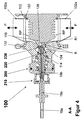
- the metering valve 100 has the product space RP bounded by a valve housing 102, wherein the product line section 12 enters and leaves the valve housing 102 via two pipe stubs 102a, which are preferably formed opposite one another on the valve housing 102 ( Figures 2 . 4 ).
- the valve housing 102 has an unspecified opening, which is sealed by a housing closure body 104 by means of a housing seal 130.
- the housing closure body 104 has an opening 104g to the product space RP (FIG. FIG. 3 ).
- a first sleeve 114 which is arranged coaxially to the passage opening 104g and displaceably engages in a sealed manner from the outside into the housing closure body 104 via a first and a second sleeve seal 136, 138, is driven by means of a spring-piston drive 200 subjected to pressure medium and thus performs a second stroke movement House.
- the valve housing 102 facing away from the end portion of the housing closure body 104 is formed as a drive piston 104f of the spring-piston actuator 200 and penetrated by the first sleeve 114 slidably and sealed.
- An associated drive housing 106 is pot-shaped, forms with the second piston seal 134 outside carrying drive piston 104f one with pressure medium, preferably control air SL ( FIG. 2 ), acted upon drive space 146 and is penetrated by the first sleeve 114 and connected to this positive and non-positive.
- a drive spring 126 of the spring-piston drive 200 is supported, on the one hand, on the drive piston 104f and, on the other hand, on a spring plate 114b formed on the first sleeve 114 in such a way that the restoring force of the drive spring 126 shifts the first sleeve 114 in the direction of the passage opening 104g.
- a space surrounding the drive spring 126 is connected to the surroundings of the metering valve 100 via at least one lantern bore 104c.
- the drive housing 106 is on its side facing away from the drive piston 104 f in a cup-shaped, bounded by a union nut 108 clamping housing 106 a clamping and Anpress worn 210, wherein the union nut 108 via conical effective surfaces on a penetrated by the end portion E forceps 120 a acts such that the end portion E, which in the present case is formed in this region as a shaft 18e of the injection needle 18b, is axially and radially fixed by and against the forceps 120a.
- the pliers 120 a terminate in a connecting part 120, which is connected to a second sleeve 116 arranged in the first sleeve 114.
- the first sleeve 114 is fixed in the bottom of the drive housing 106 between a disc 122, which rests on the ground on the one hand and is fixed by a fixed in the terminal housing 106a first locking ring 124, and a receiving in the first sleeve 114 third retaining ring 148.
- the second sleeve 116 is supported on its end facing away from the connecting part 120 on a also in the first sleeve 114 arranged Andschreibhülse 118 from which form a first sealing device 220 in cooperation with each other.
- the first sealing device 220 is completely penetrated by the end portion E and it seals in cooperation with the clamping and pressing 210 the end portion E1 of the end portion E opposite the first sleeve 114 directly or, as in the present case, indirectly by an axially and radially compressed first Sealant 140 from.
- the axial force necessary for this compression is causally generated by the union nut 108 and transmitted via the forceps 120 a to the second sleeve 116.
- a plunger 110 engages in the valve housing 102 facing away from the passage opening 104g and lies after a first stroke H in its one end position, the closed position, in the peripheral region of the passage opening 104g, which is designed as a first seat surface 104d, with a die seat surface 110b at.
- An actuating rod of the punch 110 and its penetration point through the valve housing 102 are not shown.
- the punch 110 and the penetration point are bridged by a non-designated bellows, preferably a bellows or corrugated tube, cohesively.
- the valve housing 102 is connected on the one hand with the housing closure body 104 and on the other hand with a closure part, not shown, which forms the penetration point and the clamping of the bellows, each via a clamping ring connection 112.
- a space-forming punch recess 110a is provided ( FIG. 3 ), which forms the initial space R together with an in the housing closure body 104 between the passage opening 104g and the front, sliding end of the first sleeve 114 space, wherein the space located in the housing closure body 104 via the inlet and the outlet channel 104a, 104b for the fluid F, which may be sterile vapor D, sterile condensate K or sterile air L, is in each case connected to the environment of the metering valve 100 ( FIG. 2 ).
- the fluid F which may be sterile vapor D, sterile condensate K or sterile air L
- the metering valve 100 further has a closure piston 128, which is penetrated by the end portion E1 of the end portion E and arranged on a first sleeve 114 on the end, in the initial space R projecting into the journal 114a, preferably axially and radially slidably limited limited ,
- the closure piston 128 is in its generated by the restoring force of the drive spring 126 after the second stroke h end position, its closed position, in the peripheral region of the passage opening 104g, which is formed as a second seat 104e, preferably with a first piston seal 132 sealingly.
- the closing piston 128 divides the partial space R1 from the initial space R between itself and the punch recess 110a, and the closing piston 128 is sealed relative to the end-side part E1 by an axially and radially compressed second sealing means 142 in the context of a second sealing device 230.
- the second sealing means 142 has separated from the end-side part E1 by the intrinsic elasticity inherent therein, and all surfaces and regions of the initial space R are subject to the loading accessible with the fluid F.
- the pressing and the widening of the second sealing means 142 are preferably achieved in that the closure piston 128 and the bearing pin 114a engaging in it form a wedge-shaped annular space enclosing the end-side part E1, which tapers from the inside to the outside and receives the second sealing means 142.
- the flanks of the wedge-shaped annular space are so far approximated that the second sealant 142 is axially and radially compressed and thus sealed against the end-side part E1.
- the flanks of the wedge-shaped annular space are so far apart that the second sealing means 142 expands under the action of its inherent elasticity and is far away from the end-side part E1.
- the construction of the metering valve 100 has been described above with reference to FIGS. 2 to 4 Where it is in the so-called. Waiting position, and the FIG. 5 In which it is in the sterilization position described.
- the embedding of the metering valve 100 in the metering device 10 shows FIG. 1 ,
- the waiting position according to the FIGS. 2 to 4 is the drive space 146 not with pressure medium, the control air SL ( FIG. 2 ) .
- the closure piston 128 is pressed under the influence of the restoring force of the drive spring 126 in its sealing closed position on the second seat surface 104e.
- the first and second sealing means 140, 142 seal the injection needle 18b in the manner described above. (From the initial room R FIG.
- the closure piston 128 is moved by acting on the drive chamber 146 with control air SL in its open position.
- the first sealant 140 remains compressed and the second sealant 142 is radially expanded so that the end portion E1 remains permanently positioned and sealed to the first sealant 140 and from there, freely floats into the initial space R of any fluid F.
- fluid F sterile steam D for sterilization, sterile air L for cooling, sterile condensate K for flushing or sterile air L for blowing out can be supplied.
- the product line section 12 is usually scheduled for chemical cleaning, so-called CIP (cleaning in place ), by means of acid and / or lye and rinse water, also a relevant CIP cleaning of all relevant areas of the metering valve 100 can be carried out, wherein the respective cleaning agent via the product line section 12 and is discharged via the drain passage 104b respectively.
- CIP cleaning in place
- the closure piston 128 After sterilization, cooling and, if necessary, rinsing with the subsequent blowing according to FIG. 5 the closure piston 128 is first transferred to the closed position after the elimination of the control air SL under the restoring force of the drive spring 126, the waiting position according to the FIGS. 2 to 4 , The stamp 110 can then be moved to its open position by the first stroke H and the subspace R1 can be opened to the product space RP, in which the base product P flows.
- the metering valve 100 is now in the metering according to FIG. 6 In which the additive Z via the outlet opening of the end portion E1 of the end portion E, in this case the injection needle 18b is in proportion to quantity metered into the flowing product P base.
- a fixed or a ductile deformable tube with a smooth end 18c can also be used analogously in the same way.
- the end part E1 ( FIG. 3 ) of the end section E can also be designed separately from the latter and with a controllable outlet opening. This would then be, for example, a controllable small metering valve.
- the optional coupling of this small metering valve to the end portion E can then, for example, again via an injection needle 18b, a solid or ductile deformable tube with smooth end 18c or an adapter 18d for producing a fluidworkingen connection done, to these conditions, the remaining inventive procedural solution characteristics mutatis mutandis to be transferred.
- the bag 18 and at least the sampling line 18a in the delivery state form a sterile unit and find use in this embodiment in the metering device 10 ( FIG. 1 ).
- the essential features of this unit, its pre- and post-treatment, are briefly described below.
- the bag 18, which preferably has a capacity of, for example, 5 or 10 liters, for the sterile storage of liquid aseptic additives Z, such as enzymes, flavors, colors, lipids, probiotic bacteria and other nutrients, is a flat, rectangular in its unfilled state , Made of a suitable plastic structure, as it is used in its basic form in medical technology application. As a starting form usually a tubular film with a suitable diameter is used, which is a required assembled axial length and then closed at the two open ends by welding, and then on or in these ends, the respective application-specific precautions, peculiarities or requirements are realized. It preferably consists of semi-transparent ethylene vinyl acetate (EVA) with light protection.
- EVA semi-transparent ethylene vinyl acetate
- a so-called. Knick valve arranged with the irreversible breaking a barrier at a predetermined breaking point a fluid possiblye connection between the interior of the bag 18 and the removal arrangement is made.
- the removal arrangement consists of the already described removal line 18 a, preferably a removal hose, the tight and tight with the vorg. Connection is connected. This may be a positive and / or non-positive or even a material connection.
- the extraction line 18a At the end of the extraction line 18a facing away from the coupling, it opens into the described injection needle 18b, with which the additive Z is metered under aseptic conditions into the base product P flowing in the product line section 12. Seen in the direction of flow of the additive Z, the removal arrangement in front of the injection needle 18b preferably has a check valve and a filter in front of it.
- the barrier of the kink valve is broken only after hanging the bag 18 via a preferred three-point suspension in the metering device 10 and shortly before the start of the aseptic dosing at the predetermined breaking point.
- the bag 18 and the attached thereto and fixed thereto removal assembly are sterilized as a unit together with a suitable means. This happens even before the filling of the bag 18 with the additive Z.
- the above-mentioned buckling valve has a constriction and this acts as a predetermined breaking point.
- a sufficient bending moment transverse to the longitudinal axis of the kink valve leads to a complete break of the kink valve at this point, so that the kink valve is separated into two parts.
- the kink valve is inserted into the port with the free end of the first part first, and so on far axially displaced, that after breaking the kink valve at the predetermined breaking point of the isolated, smaller diameter first part passes into the bag 18, so that an unobstructed access from the interior of the bag 18 is ensured by a break in the second part only exposed inner passage to the removal arrangement.
Landscapes
- Life Sciences & Earth Sciences (AREA)
- Engineering & Computer Science (AREA)
- Polymers & Plastics (AREA)
- Food Science & Technology (AREA)
- Chemical & Material Sciences (AREA)
- Zoology (AREA)
- Wood Science & Technology (AREA)
- Health & Medical Sciences (AREA)
- Epidemiology (AREA)
- Veterinary Medicine (AREA)
- Public Health (AREA)
- General Health & Medical Sciences (AREA)
- Animal Behavior & Ethology (AREA)
- Physics & Mathematics (AREA)
- General Physics & Mathematics (AREA)
- Fluid Mechanics (AREA)
- Basic Packing Technique (AREA)
- Feeding, Discharge, Calcimining, Fusing, And Gas-Generation Devices (AREA)
Claims (23)
- Procédé pour le dosage aseptique d'un additif liquide (Z) dans un écoulement forcé d'un produit de base (P), l'additif (Z) étant prélevé à partir d'un récipient de stockage (18) dans des conditions aseptiques au moyen d'une conduite de prélèvement (18a) et étant ajouté au produit de base (P) s'écoulant à travers une chambre de produit (RP), par le biais d'une section d'extrémité (E) de la conduite de prélèvement (18a),
caractérisé par les étapes de traitement suivantes pour la section d'extrémité (E), avant que celle-ci ne délivre l'additif (Z) au produit de base (P) :(a) la section d'extrémité (E) est temporairement insérée par un côté partiellement dans une chambre initiale (R), où elle est ensuite positionnée de façon permanente et étanchéifiée au niveau du point de passage vers cette chambre initiale (R), celle-ci pouvant être ouverte sélectivement vers la chambre de produit (RP) ;(b) une partie côté extrémité (E1) de la section d'extrémité (E) faisant saillie dans la chambre initiale (R) de façon étanche est au moins stérilisée, les régions de la chambre initiale (R) étant également incluses en totalité dans ce traitement ;(c) la partie côté extrémité (E1) de la section d'extrémité (E) est insérée partiellement dans une chambre partielle (R1) séparable de façon étanche par rapport à la chambre initiale (R), la partie côté extrémité (E1) étant étanchéifiée au niveau du point de passage vers la chambre partielle (R1) à la fin de l'insertion, à l'aide d'un moyen d'étanchéité traité selon l'étape de traitement (b) ;(d) la chambre partielle (R1) est ouverte sur la chambre de produit (RP). - Procédé selon la revendication 1,
caractérisé en ce que
la stérilisation selon l'étape de traitement (b) est suivie d'un refroidissement dans des conditions stériles. - Procédé selon la revendication 2,
caractérisé en ce que
la stérilisation est réalisée avec une vapeur stérile (D) et le refroidissement avec de l'air stérile (L). - Procédé selon la revendication 2 ou 3,
caractérisé en ce que
la stérilisation et le refroidissement sont réalisés en aval de la partie côté extrémité (E1) à traiter, en surveillant la température. - Procédé selon l'une des revendications 2 à 4,
caractérisé en ce que
la stérilisation est réalisée à une température supérieure à 125°C, et le refroidissement à une température inférieure à 50°C. - Procédé selon l'une des revendications précédentes,
caractérisé en ce que
la conduite de prélèvement (18a) reste exempte d'additif (Z) jusqu'à la fin de l'étape de traitement (b) ou (c), et en ce que l'additif (Z) est ensuite guidé jusqu'au point de sortie de la partie côté extrémité (E1). - Procédé selon la revendication 6,
caractérisé en ce que
un rinçage de la chambre initiale (R) avec un condensat stérile (K) à une température inférieure à 50°C peut être réalisé au choix. - Procédé selon la revendication 7,
caractérisé en ce que
suite au rinçage de la chambre initiale (R), celle-ci est purgée avec de l'air stérile (L). - Procédé selon l'une des revendications précédentes,
caractérisé en ce que
le transport de l'additif (Z) dans la conduite de prélèvement (18a) est effectué de manière forcée. - Procédé selon l'une des revendications précédentes,
caractérisé en ce que
l'additif (Z) est dosé en quantités proportionnelles au produit de base (P) en écoulement. - Dispositif de dosage (10 ; 10.1 ; 10.2) pour l'exécution du procédé selon l'une des revendications précédentes, comprenant une section de conduite de produit (12) traversée de manière forcée par le produit de base (P), au moins un récipient de stockage (18 ; 18.1 ; 18.2) pour l'additif (Z), lequel est respectivement relié à un point de dosage (I ; 1.1 ; 1.2) correspondant situé sur ou dans la section de conduite de produit (12) par le biais de la conduite de prélèvement (18a), des troisièmes moyens (22) pour l'écoulement forcé de l'additif (Z), des premiers et deuxièmes moyens (14, 20) pour la détection quantitative du produit de base (P) et de l'additif (Z), des quatrièmes moyens (24) pour l'apport de vapeur stérile (D) et un dispositif de commande (50) attribué au dispositif de dosage (10 ; 10.1, 10.2),
caractérisé en ce que
le point de dosage (I ; I.1 ; 1.2) est prévu à l'intérieur d'une soupape de dosage (100) formant la chambre de produit (PR) dans laquelle la section de conduite de produit (12) débouche et d'où celle-ci repart, la chambre initiale (R) et la chambre partielle (R1) ainsi qu'une admission de la section d'extrémité (E) et de la partie côté extrémité (E1). - Dispositif de dosage selon la revendication 11,
caractérisé en ce que
la partie de la chambre initiale (R) restant suite à la séparation de la chambre partielle (R1) comporte un canal d'alimentation et un canal d'évacuation (104a, 104b), lesquels peuvent être verrouillés respectivement de manière sélective au moyen d'une soupape d'arrêt (26, 28) correspondante, le canal d'alimentation (104a) pouvant être relié au moins au quatrième moyen (24) pour l'apport de vapeur stérile (D). - Dispositif de dosage selon la revendication 12,
caractérisé en ce que
le canal d'alimentation (104a) peut être relié de manière sélective à un cinquième moyen (24a) pour l'apport de condensat stérile (K) et/ou à un sixième moyen (24b) pour l'apport d'air stérile (L). - Dispositif de dosage selon la revendication 12 ou 13,
caractérisé en ce que
une sonde de température (38) est disposée dans le canal d'évacuation (104b) ou en aval directement à la suite du canal d'évacuation (104b). - Dispositif de dosage selon l'une des revendications 11 à 14,
caractérisé en ce que
le récipient de stockage (18) et au moins la conduite de prélèvement (18a) forment une unité stérile dans l'état de livraison. - Dispositif de dosage selon l'une des revendications 11 à 15,
caractérisé en ce que
la section d'extrémité (E) avec la partie côté extrémité (E1) intégrale est conçue d'un seul tenant comme une aiguille d'injection (18b) ou comme un tube à extrémité lisse (18c). - Dispositif de dosage selon l'une des revendications 11 à 15,
caractérisé en ce que
la partie côté extrémité (E1) est conçue séparément de la section d'extrémité (E) et avec une ouverture d'évacuation contrôlable, en ce que la section d'extrémité (E) est conçue comme une aiguille d'injection (18b) ou comme un tube à extrémité lisse (18c) ou comme un adaptateur (18d) destiné à établir une liaison fluidique avec la partie côté extrémité (E1), et en ce que la section d'extrémité (E) est reliée fluidiquement à la partie côté extrémité (E1). - Dispositif de dosage selon l'une des revendications 11 à 17,
caractérisé en ce que
le récipient de stockage (18) est conçu sous la forme d'une poche souple, et en ce que la poche (18) remplie d'additif (Z) et au moins la conduite de prélèvement (18a) sont enfermées de façon étanche dans un suremballage en PE et soumises à un rayonnement gamma pour une stérilisation extérieure. - Soupape de dosage (100) pour un dispositif de dosage (10) selon l'une des revendications 11 à 18,
caractérisée par• un boîtier de soupape (102) bordant la chambre de produit (RP), disposé dans la section de conduite de produit (12),• un corps de fermeture de boîtier (104) fermant le boîtier de soupape (102) sur un côté, avec une ouverture de passage (104g) vers la chambre de produit (RP),• une première douille (114) disposée coaxialement à l'ouverture de passage (104g) et s'engageant de façon coulissante et étanche depuis l'extérieur dans le corps de fermeture de boîtier (104), laquelle est entraînée au moyen d'un entraînement à ressort et piston (200) soumis à un fluide sous pression, exécutant ainsi un deuxième mouvement de course (h),• un dispositif de serrage et de pression (210) traversé par la section d'extrémité (E) et fixant celle-ci radialement et axialement,• un premier dispositif d'étanchéité (220) reçu à l'intérieur de la première douille (114), lequel est traversé par la section d'extrémité (E) et assure l'étanchéité de la partie côté extrémité (E1) de la section d'extrémité (E) par rapport à la première douille (114), directement ou indirectement par le biais d'un premier moyen d'étanchéité (140) comprimé axialement et radialement, en coopération avec le dispositif de serrage et de pression (210),• un tampon (110) s'engageant dans le boîtier de soupape (102) par le côté de celui-ci qui est opposé à l'ouverture de passage (104g), et s'appliquant dans sa position finale avec une surface d'appui de tampon (110b) dans la région périphérique de l'ouverture de passage (104g) formée comme une première surface d'appui (104d), après un premier mouvement de course (H),• un évidement de tampon (110a) formant un espace, prévu dans la surface frontale du tampon (110) qui est tournée vers l'ouverture de passage (104g), lequel forme la chambre initiale (R) ensemble avec une chambre située dans le corps de fermeture de boîtier (104) entre l'ouverture de passage (104g) et l'extrémité avant déplaçable de la première douille (114), l'espace situé dans le corps de fermeture de boîtier (104) étant relié respectivement à l'environnement de la soupape de dosage (100) par le biais d'un canal d'alimentation et du canal d'évacuation (104a, 104b),• un piston de fermeture (128) traversé par la partie côté extrémité (E1) de la section d'extrémité (E) et disposé sur un tourillon (114a) disposé côté extrémité sur la première douille (114) et faisant saillie dans la chambre initiale (R), lequel s'applique de façon étanche dans la région périphérique de l'ouverture de passage (104g) formant la deuxième surface d'appui (104e), dans sa position finale, la position de fermeture, atteinte après le deuxième mouvement de course à l'aide d'un ressort d'entraînement (126) dans l'entraînement à ressort et piston (200), le piston de fermeture (128) séparant la chambre partielle (R1) d'avec la chambre initiale (R) dans sa position de fermeture entre lui-même et l'évidement de tampon (110a), et le piston de fermeture (128) étant étanchéifié par rapport à la partie côté extrémité (E1) par un deuxième moyen d'étanchéité (142) dans le cadre d'un deuxième dispositif d'étanchéité (230), et• une autre position finale du piston de fermeture (128) atteinte avec le deuxième mouvement de course (h), la position d'ouverture, dans laquelle le deuxième moyen d'étanchéité (142) s'est détaché de la partie côté extrémité (E1) sur une largeur de fente, et toutes les surfaces et régions de la chambre initiale (R) sont accessibles pour être soumises à un fluide (F) composé de vapeur stérile (D) ou d'air stérile (L) ou de condensat stérile (K). - Soupape de dosage selon la revendication 19,
caractérisée en ce que
la section d'extrémité du corps de fermeture de boîtier (104) qui est opposée au boîtier de soupape (102) est formée comme un piston d'entraînement (104f) de l'entraînement à ressort et piston (200) et traversée de façon coulissante et étanche par la première douille (114), en ce qu'un boîtier d'entraînement (106) correspondant et conçu en forme de pot et traversé par la première douille (114) tout en étant relié à celle-ci par complémentarité de forme ou à force, et en ce que le ressort d'entraînement (126) s'appuie d'une part sur le piston d'entraînement (104f) et d'autre part sur la première douille (114) de telle façon que la force de rappel du ressort d'entraînement (126) fait passer le piston de fermeture (128) dans sa position de fermeture. - Soupape de dosage selon la revendication 20,
caractérisée en ce que le boîtier d'entraînement (106), sur son côté opposé au piston d'entraînement (104f), se prolonge en un boîtier de serrage (106a) en forme de pot du dispositif de serrage et de pression (210) délimité par un écrou-raccord (108), et en ce que l'écrou-raccord (108) agit avec des surfaces actives coniques sur une pince (120a) traversée par la section d'extrémité (E) de telle façon que la section d'extrémité (E) est fixée axialement et radialement par la pince (120a). - Soupape de dosage selon la revendication 21,
caractérisée en ce que
la pince (120a) est reliée à une extrémité d'une deuxième douille (116) reçue dans la première douille (114) et entièrement traversée par la section d'extrémité (E), et agit axialement sur celle-ci de manière à ce que celle-ci comprime le premier moyen d'étanchéité (140) axialement et radialement avec son autre extrémité. - Soupape de dosage selon l'une des revendications 19 à 22,
caractérisée en ce que
le piston de fermeture (128) et le tourillon (114a) s'engageant dans celui-ci forment un espace annulaire cunéiforme entourant la partie côté extrémité (E1), lequel s'affine de l'intérieur vers l'extérieur et reçoit le deuxième moyen d'étanchéité (142), en ce que dans la position de fermeture du piston de fermeture (128), les flancs de l'espace annulaire cunéiforme sont rapprochés l'un de l'autre au point que le deuxième moyen d'étanchéité (142) est comprimé axialement et radialement et étanchéifié par rapport à la partie côté extrémité (E1), et en ce que dans la position d'ouverture du piston de fermeture (128), les flancs de l'espace annulaire cunéiforme sont éloignés l'un de l'autre au point que le deuxième moyen d'étanchéité (142) s'élargit et se retrouve à une distance de fente de la partie côté extrémité (E1).
Applications Claiming Priority (1)
| Application Number | Priority Date | Filing Date | Title |
|---|---|---|---|
| PCT/EP2012/001020 WO2013131529A1 (fr) | 2012-03-08 | 2012-03-08 | Procédé, dispositif de dosage et soupape de dosage, pour le dosage aseptique d'un additif liquide, dans un écoulement forcé d'un produit de base |
Publications (2)
| Publication Number | Publication Date |
|---|---|
| EP2822406A1 EP2822406A1 (fr) | 2015-01-14 |
| EP2822406B1 true EP2822406B1 (fr) | 2016-11-30 |
Family
ID=45937186
Family Applications (1)
| Application Number | Title | Priority Date | Filing Date |
|---|---|---|---|
| EP12712927.8A Active EP2822406B1 (fr) | 2012-03-08 | 2012-03-08 | Procédé, dispositif de dosage et soupape de dosage, pour le dosage aseptique d'un additif liquide, dans un écoulement forcé d'un produit de base |
Country Status (6)
| Country | Link |
|---|---|
| US (2) | US9491964B2 (fr) |
| EP (1) | EP2822406B1 (fr) |
| DK (1) | DK2822406T3 (fr) |
| MX (1) | MX2014010621A (fr) |
| PL (1) | PL2822406T3 (fr) |
| WO (1) | WO2013131529A1 (fr) |
Families Citing this family (6)
| Publication number | Priority date | Publication date | Assignee | Title |
|---|---|---|---|---|
| DK3338561T3 (da) | 2016-12-20 | 2020-11-30 | Tetra Laval Holdings & Finance | Anordning til overførsel af fødevarebestanddel |
| CN111244878A (zh) * | 2020-01-18 | 2020-06-05 | 芜湖明远电力工程咨询设计有限公司 | 一种气体绝缘金属封闭输电线路 |
| CN116114757B (zh) * | 2021-11-15 | 2024-06-25 | 内蒙古伊利实业集团股份有限公司 | 一种无乳糖牛奶及其制备方法 |
| CN116293173B (zh) * | 2023-03-22 | 2025-12-23 | 浙江诸暨天昱园林有限公司 | 一种用于市政管道端口的封堵装置 |
| CN117990184B (zh) * | 2024-04-07 | 2024-06-25 | 中国市政工程华北设计研究总院有限公司 | 一种具有多点位监测功能的高精度激光泥位计 |
| CN119368272B (zh) * | 2024-11-26 | 2025-04-11 | 科瑞斯(常州)粉体工程有限公司 | 一种防残留的包装机械用挤压破碎机 |
Family Cites Families (6)
| Publication number | Priority date | Publication date | Assignee | Title |
|---|---|---|---|---|
| DE4008845A1 (de) * | 1990-03-20 | 1991-09-26 | Granini Gmbh | Verfahren zum aufbereiten von aus fruchtsaftkonzentrat o.dgl. hergestellten getraenken |
| US6599546B2 (en) * | 2001-05-18 | 2003-07-29 | The Coca Cola Company | Process and apparatus for in-line production of heat-processed beverage made from concentrate |
| WO2005011409A1 (fr) * | 2003-07-30 | 2005-02-10 | Fmc Technologies, Inc. | Systeme et procede de traitement aseptique |
| DE10337057A1 (de) * | 2003-08-12 | 2005-03-17 | Wesergold Getränkeindustrie GmbH & Co. KG | Vorrichtung und Verfahren zur Dosierung von Aromen bei der kaltaseptischen Abfüllung von Getränken |
| US7988674B2 (en) * | 2006-10-30 | 2011-08-02 | Medtronic, Inc. | Externally releasable body portal anchors and systems |
| DE102007056833A1 (de) * | 2007-11-26 | 2009-05-28 | Gea Tds Gmbh | Verfahren und Vorrichtung zum Erzeugen eines sterilisierenden Gasgemischs |
-
2012
- 2012-03-08 EP EP12712927.8A patent/EP2822406B1/fr active Active
- 2012-03-08 DK DK12712927.8T patent/DK2822406T3/en active
- 2012-03-08 US US14/383,437 patent/US9491964B2/en active Active
- 2012-03-08 WO PCT/EP2012/001020 patent/WO2013131529A1/fr not_active Ceased
- 2012-03-08 PL PL12712927T patent/PL2822406T3/pl unknown
- 2012-03-08 MX MX2014010621A patent/MX2014010621A/es unknown
-
2016
- 2016-09-23 US US15/274,349 patent/US9936725B2/en active Active
Also Published As
| Publication number | Publication date |
|---|---|
| PL2822406T3 (pl) | 2017-07-31 |
| US20150140183A1 (en) | 2015-05-21 |
| MX2014010621A (es) | 2015-08-14 |
| US9491964B2 (en) | 2016-11-15 |
| EP2822406A1 (fr) | 2015-01-14 |
| DK2822406T3 (en) | 2017-03-13 |
| WO2013131529A1 (fr) | 2013-09-12 |
| US20170006903A1 (en) | 2017-01-12 |
| US9936725B2 (en) | 2018-04-10 |
Similar Documents
| Publication | Publication Date | Title |
|---|---|---|
| EP2822406B1 (fr) | Procédé, dispositif de dosage et soupape de dosage, pour le dosage aseptique d'un additif liquide, dans un écoulement forcé d'un produit de base | |
| EP2114344B1 (fr) | Procédé de remplissage d'un récipient avec un liquide médical et de fermeture du récipient et bouchon de remplissage et de fermeture de récipients contenant des liquides médicaux | |
| DE102011077717B4 (de) | Doppelsitzventil-Vorrichtung mit Festkörperkontakt | |
| DE3513204A1 (de) | Zweibeutel-system fuer die peritonealdialyse sowie konnektor hierfuer | |
| AT515905B1 (de) | Steril-Befüll- bzw. Spüleinrichtung | |
| DE102011106852B4 (de) | Vorrichtung zum aseptischen Verbinden und Trennen von Verbindungen zwischen Behältern | |
| DE10252217B4 (de) | Probenahmeventil und damit durchführbares Verfahren zur sterilen Entnahme von Proben aus Fermentern oder Bioreaktoren | |
| EP3049332B1 (fr) | Installation de remplissage aseptique d'un récipient | |
| EP1930031A1 (fr) | Méthode pour stériliser la pièce de raccordement d'un système de sac-dans-réservoir et l'appareil correspondant pour la stérilisation | |
| EP2628474B1 (fr) | Sac destiné à approvisionner et extraire un additif liquide sous conditions aseptiques | |
| DE102007044647A1 (de) | Vorrichtung zum Steuern eines Fluidverlaufes | |
| WO2015121296A1 (fr) | Dispositif de raccordement stérile d'articles médicaux à usage unique | |
| EP3070391A1 (fr) | Couplage, procede et installation de preparation de boissons | |
| DE112014002326T5 (de) | Mechanisches Dichtungsversorgungssystem | |
| DE102010006919A1 (de) | Packmittelbehandlungsanlage mit Messung des Sterilisationsmediums | |
| DE102004055378B4 (de) | Probenentnahmevorrichtung sowie Probenaufnahmebehälter | |
| DE102012109981B4 (de) | Vorrichtung zur Kohlenstoffdioxidtherapie | |
| DE102024002527A1 (de) | Vorrichtung | |
| DE202011108186U1 (de) | Beutel zur Bevorratung und Entnahme eines flüssigen Zusatzstoffes unter aseptischen Bedingungen | |
| DE19925641A1 (de) | Aufsteckbares Sterilfilter | |
| WO2025056327A1 (fr) | Procédé de préparation d'une opération de remplissage | |
| WO2022008569A1 (fr) | Dispositif pour ajouter de manière dosée un additif à un fluide | |
| DE202011004400U1 (de) | Verschlussvorrichtung für ein Probenahmegefäß | |
| EP1721595A1 (fr) | Récipient pour délivrer des liquides médicaux | |
| DE1976873U (de) | Steuerventileinrichtung fuer leitungsanlagen zur behandlung von fluessigkeiten |
Legal Events
| Date | Code | Title | Description |
|---|---|---|---|
| PUAI | Public reference made under article 153(3) epc to a published international application that has entered the european phase |
Free format text: ORIGINAL CODE: 0009012 |
|
| 17P | Request for examination filed |
Effective date: 20140903 |
|
| AK | Designated contracting states |
Kind code of ref document: A1 Designated state(s): AL AT BE BG CH CY CZ DE DK EE ES FI FR GB GR HR HU IE IS IT LI LT LU LV MC MK MT NL NO PL PT RO RS SE SI SK SM TR |
|
| AX | Request for extension of the european patent |
Extension state: BA ME |
|
| DAX | Request for extension of the european patent (deleted) | ||
| GRAP | Despatch of communication of intention to grant a patent |
Free format text: ORIGINAL CODE: EPIDOSNIGR1 |
|
| INTG | Intention to grant announced |
Effective date: 20160314 |
|
| GRAF | Information related to payment of grant fee modified |
Free format text: ORIGINAL CODE: EPIDOSCIGR3 |
|
| GRAS | Grant fee paid |
Free format text: ORIGINAL CODE: EPIDOSNIGR3 |
|
| GRAA | (expected) grant |
Free format text: ORIGINAL CODE: 0009210 |
|
| AK | Designated contracting states |
Kind code of ref document: B1 Designated state(s): AL AT BE BG CH CY CZ DE DK EE ES FI FR GB GR HR HU IE IS IT LI LT LU LV MC MK MT NL NO PL PT RO RS SE SI SK SM TR |
|
| REG | Reference to a national code |
Ref country code: CH Ref legal event code: EP Ref country code: GB Ref legal event code: FG4D Free format text: NOT ENGLISH |
|
| REG | Reference to a national code |
Ref country code: AT Ref legal event code: REF Ref document number: 848936 Country of ref document: AT Kind code of ref document: T Effective date: 20161215 |
|
| REG | Reference to a national code |
Ref country code: IE Ref legal event code: FG4D Free format text: LANGUAGE OF EP DOCUMENT: GERMAN |
|
| REG | Reference to a national code |
Ref country code: DE Ref legal event code: R096 Ref document number: 502012008910 Country of ref document: DE |
|
| REG | Reference to a national code |
Ref country code: NL Ref legal event code: FP |
|
| REG | Reference to a national code |
Ref country code: DE Ref legal event code: R082 Ref document number: 502012008910 Country of ref document: DE |
|
| PG25 | Lapsed in a contracting state [announced via postgrant information from national office to epo] |
Ref country code: LV Free format text: LAPSE BECAUSE OF FAILURE TO SUBMIT A TRANSLATION OF THE DESCRIPTION OR TO PAY THE FEE WITHIN THE PRESCRIBED TIME-LIMIT Effective date: 20161130 |
|
| REG | Reference to a national code |
Ref country code: PT Ref legal event code: SC4A Ref document number: 2822406 Country of ref document: PT Date of ref document: 20170308 Kind code of ref document: T Free format text: AVAILABILITY OF NATIONAL TRANSLATION Effective date: 20170227 |
|
| REG | Reference to a national code |
Ref country code: DK Ref legal event code: T3 Effective date: 20170306 |
|
| REG | Reference to a national code |
Ref country code: FR Ref legal event code: PLFP Year of fee payment: 6 |
|
| REG | Reference to a national code |
Ref country code: LT Ref legal event code: MG4D |
|
| REG | Reference to a national code |
Ref country code: CH Ref legal event code: NV Representative=s name: ISLER AND PEDRAZZINI AG, CH |
|
| PG25 | Lapsed in a contracting state [announced via postgrant information from national office to epo] |
Ref country code: NO Free format text: LAPSE BECAUSE OF FAILURE TO SUBMIT A TRANSLATION OF THE DESCRIPTION OR TO PAY THE FEE WITHIN THE PRESCRIBED TIME-LIMIT Effective date: 20170228 Ref country code: GR Free format text: LAPSE BECAUSE OF FAILURE TO SUBMIT A TRANSLATION OF THE DESCRIPTION OR TO PAY THE FEE WITHIN THE PRESCRIBED TIME-LIMIT Effective date: 20170301 Ref country code: LT Free format text: LAPSE BECAUSE OF FAILURE TO SUBMIT A TRANSLATION OF THE DESCRIPTION OR TO PAY THE FEE WITHIN THE PRESCRIBED TIME-LIMIT Effective date: 20161130 Ref country code: SE Free format text: LAPSE BECAUSE OF FAILURE TO SUBMIT A TRANSLATION OF THE DESCRIPTION OR TO PAY THE FEE WITHIN THE PRESCRIBED TIME-LIMIT Effective date: 20161130 |
|
| PG25 | Lapsed in a contracting state [announced via postgrant information from national office to epo] |
Ref country code: HR Free format text: LAPSE BECAUSE OF FAILURE TO SUBMIT A TRANSLATION OF THE DESCRIPTION OR TO PAY THE FEE WITHIN THE PRESCRIBED TIME-LIMIT Effective date: 20161130 Ref country code: RS Free format text: LAPSE BECAUSE OF FAILURE TO SUBMIT A TRANSLATION OF THE DESCRIPTION OR TO PAY THE FEE WITHIN THE PRESCRIBED TIME-LIMIT Effective date: 20161130 Ref country code: FI Free format text: LAPSE BECAUSE OF FAILURE TO SUBMIT A TRANSLATION OF THE DESCRIPTION OR TO PAY THE FEE WITHIN THE PRESCRIBED TIME-LIMIT Effective date: 20161130 Ref country code: ES Free format text: LAPSE BECAUSE OF FAILURE TO SUBMIT A TRANSLATION OF THE DESCRIPTION OR TO PAY THE FEE WITHIN THE PRESCRIBED TIME-LIMIT Effective date: 20161130 |
|
| PGFP | Annual fee paid to national office [announced via postgrant information from national office to epo] |
Ref country code: GB Payment date: 20170327 Year of fee payment: 6 Ref country code: IE Payment date: 20170329 Year of fee payment: 6 |
|
| PG25 | Lapsed in a contracting state [announced via postgrant information from national office to epo] |
Ref country code: CZ Free format text: LAPSE BECAUSE OF FAILURE TO SUBMIT A TRANSLATION OF THE DESCRIPTION OR TO PAY THE FEE WITHIN THE PRESCRIBED TIME-LIMIT Effective date: 20161130 Ref country code: EE Free format text: LAPSE BECAUSE OF FAILURE TO SUBMIT A TRANSLATION OF THE DESCRIPTION OR TO PAY THE FEE WITHIN THE PRESCRIBED TIME-LIMIT Effective date: 20161130 Ref country code: SK Free format text: LAPSE BECAUSE OF FAILURE TO SUBMIT A TRANSLATION OF THE DESCRIPTION OR TO PAY THE FEE WITHIN THE PRESCRIBED TIME-LIMIT Effective date: 20161130 Ref country code: RO Free format text: LAPSE BECAUSE OF FAILURE TO SUBMIT A TRANSLATION OF THE DESCRIPTION OR TO PAY THE FEE WITHIN THE PRESCRIBED TIME-LIMIT Effective date: 20161130 |
|
| PG25 | Lapsed in a contracting state [announced via postgrant information from national office to epo] |
Ref country code: SM Free format text: LAPSE BECAUSE OF FAILURE TO SUBMIT A TRANSLATION OF THE DESCRIPTION OR TO PAY THE FEE WITHIN THE PRESCRIBED TIME-LIMIT Effective date: 20161130 Ref country code: BG Free format text: LAPSE BECAUSE OF FAILURE TO SUBMIT A TRANSLATION OF THE DESCRIPTION OR TO PAY THE FEE WITHIN THE PRESCRIBED TIME-LIMIT Effective date: 20170228 |
|
| REG | Reference to a national code |
Ref country code: DE Ref legal event code: R097 Ref document number: 502012008910 Country of ref document: DE |
|
| PLBE | No opposition filed within time limit |
Free format text: ORIGINAL CODE: 0009261 |
|
| STAA | Information on the status of an ep patent application or granted ep patent |
Free format text: STATUS: NO OPPOSITION FILED WITHIN TIME LIMIT |
|
| 26N | No opposition filed |
Effective date: 20170831 |
|
| PG25 | Lapsed in a contracting state [announced via postgrant information from national office to epo] |
Ref country code: MC Free format text: LAPSE BECAUSE OF FAILURE TO SUBMIT A TRANSLATION OF THE DESCRIPTION OR TO PAY THE FEE WITHIN THE PRESCRIBED TIME-LIMIT Effective date: 20161130 Ref country code: SI Free format text: LAPSE BECAUSE OF FAILURE TO SUBMIT A TRANSLATION OF THE DESCRIPTION OR TO PAY THE FEE WITHIN THE PRESCRIBED TIME-LIMIT Effective date: 20161130 |
|
| PG25 | Lapsed in a contracting state [announced via postgrant information from national office to epo] |
Ref country code: LU Free format text: LAPSE BECAUSE OF NON-PAYMENT OF DUE FEES Effective date: 20170308 |
|
| REG | Reference to a national code |
Ref country code: FR Ref legal event code: PLFP Year of fee payment: 7 |
|
| PGFP | Annual fee paid to national office [announced via postgrant information from national office to epo] |
Ref country code: PT Payment date: 20180226 Year of fee payment: 7 Ref country code: BE Payment date: 20180322 Year of fee payment: 7 |
|
| PG25 | Lapsed in a contracting state [announced via postgrant information from national office to epo] |
Ref country code: MT Free format text: LAPSE BECAUSE OF FAILURE TO SUBMIT A TRANSLATION OF THE DESCRIPTION OR TO PAY THE FEE WITHIN THE PRESCRIBED TIME-LIMIT Effective date: 20161130 |
|
| GBPC | Gb: european patent ceased through non-payment of renewal fee |
Effective date: 20180308 |
|
| REG | Reference to a national code |
Ref country code: IE Ref legal event code: MM4A |
|
| PG25 | Lapsed in a contracting state [announced via postgrant information from national office to epo] |
Ref country code: IE Free format text: LAPSE BECAUSE OF NON-PAYMENT OF DUE FEES Effective date: 20180308 |
|
| PG25 | Lapsed in a contracting state [announced via postgrant information from national office to epo] |
Ref country code: GB Free format text: LAPSE BECAUSE OF NON-PAYMENT OF DUE FEES Effective date: 20180308 |
|
| PG25 | Lapsed in a contracting state [announced via postgrant information from national office to epo] |
Ref country code: HU Free format text: LAPSE BECAUSE OF FAILURE TO SUBMIT A TRANSLATION OF THE DESCRIPTION OR TO PAY THE FEE WITHIN THE PRESCRIBED TIME-LIMIT; INVALID AB INITIO Effective date: 20120308 |
|
| PG25 | Lapsed in a contracting state [announced via postgrant information from national office to epo] |
Ref country code: CY Free format text: LAPSE BECAUSE OF FAILURE TO SUBMIT A TRANSLATION OF THE DESCRIPTION OR TO PAY THE FEE WITHIN THE PRESCRIBED TIME-LIMIT Effective date: 20161130 Ref country code: PT Free format text: LAPSE BECAUSE OF NON-PAYMENT OF DUE FEES Effective date: 20190909 |
|
| PG25 | Lapsed in a contracting state [announced via postgrant information from national office to epo] |
Ref country code: MK Free format text: LAPSE BECAUSE OF FAILURE TO SUBMIT A TRANSLATION OF THE DESCRIPTION OR TO PAY THE FEE WITHIN THE PRESCRIBED TIME-LIMIT Effective date: 20161130 |
|
| REG | Reference to a national code |
Ref country code: BE Ref legal event code: MM Effective date: 20190331 |
|
| PG25 | Lapsed in a contracting state [announced via postgrant information from national office to epo] |
Ref country code: BE Free format text: LAPSE BECAUSE OF NON-PAYMENT OF DUE FEES Effective date: 20190331 |
|
| PG25 | Lapsed in a contracting state [announced via postgrant information from national office to epo] |
Ref country code: TR Free format text: LAPSE BECAUSE OF FAILURE TO SUBMIT A TRANSLATION OF THE DESCRIPTION OR TO PAY THE FEE WITHIN THE PRESCRIBED TIME-LIMIT Effective date: 20161130 |
|
| PG25 | Lapsed in a contracting state [announced via postgrant information from national office to epo] |
Ref country code: AL Free format text: LAPSE BECAUSE OF FAILURE TO SUBMIT A TRANSLATION OF THE DESCRIPTION OR TO PAY THE FEE WITHIN THE PRESCRIBED TIME-LIMIT Effective date: 20161130 Ref country code: IS Free format text: LAPSE BECAUSE OF FAILURE TO SUBMIT A TRANSLATION OF THE DESCRIPTION OR TO PAY THE FEE WITHIN THE PRESCRIBED TIME-LIMIT Effective date: 20170330 |
|
| P01 | Opt-out of the competence of the unified patent court (upc) registered |
Effective date: 20230530 |
|
| REG | Reference to a national code |
Ref country code: DE Ref legal event code: R079 Ref document number: 502012008910 Country of ref document: DE Free format text: PREVIOUS MAIN CLASS: A23L0003000000 Ipc: A23B0002000000 |
|
| PGFP | Annual fee paid to national office [announced via postgrant information from national office to epo] |
Ref country code: DE Payment date: 20250331 Year of fee payment: 14 |
|
| PGFP | Annual fee paid to national office [announced via postgrant information from national office to epo] |
Ref country code: IT Payment date: 20250327 Year of fee payment: 14 |
|
| PGFP | Annual fee paid to national office [announced via postgrant information from national office to epo] |
Ref country code: CH Payment date: 20250401 Year of fee payment: 14 |
|
| REG | Reference to a national code |
Ref country code: CH Ref legal event code: U11 Free format text: ST27 STATUS EVENT CODE: U-0-0-U10-U11 (AS PROVIDED BY THE NATIONAL OFFICE) Effective date: 20260401 |
|
| PGFP | Annual fee paid to national office [announced via postgrant information from national office to epo] |
Ref country code: DK Payment date: 20260325 Year of fee payment: 15 |
|
| PGFP | Annual fee paid to national office [announced via postgrant information from national office to epo] |
Ref country code: AT Payment date: 20260319 Year of fee payment: 15 |
|
| PGFP | Annual fee paid to national office [announced via postgrant information from national office to epo] |
Ref country code: NL Payment date: 20260330 Year of fee payment: 15 |
|
| PGFP | Annual fee paid to national office [announced via postgrant information from national office to epo] |
Ref country code: FR Payment date: 20260330 Year of fee payment: 15 |
|
| PGFP | Annual fee paid to national office [announced via postgrant information from national office to epo] |
Ref country code: PL Payment date: 20260220 Year of fee payment: 15 |