EP2822724B1 - Procédé et utilisation d'une chalumeau à plasma pour le revêtement d'un substrat - Google Patents
Procédé et utilisation d'une chalumeau à plasma pour le revêtement d'un substrat Download PDFInfo
- Publication number
- EP2822724B1 EP2822724B1 EP13758351.4A EP13758351A EP2822724B1 EP 2822724 B1 EP2822724 B1 EP 2822724B1 EP 13758351 A EP13758351 A EP 13758351A EP 2822724 B1 EP2822724 B1 EP 2822724B1
- Authority
- EP
- European Patent Office
- Prior art keywords
- plasma
- module
- anode
- cathode
- gas
- Prior art date
- Legal status (The legal status is an assumption and is not a legal conclusion. Google has not performed a legal analysis and makes no representation as to the accuracy of the status listed.)
- Active
Links
Images






Classifications
-
- C—CHEMISTRY; METALLURGY
- C23—COATING METALLIC MATERIAL; COATING MATERIAL WITH METALLIC MATERIAL; CHEMICAL SURFACE TREATMENT; DIFFUSION TREATMENT OF METALLIC MATERIAL; COATING BY VACUUM EVAPORATION, BY SPUTTERING, BY ION IMPLANTATION OR BY CHEMICAL VAPOUR DEPOSITION, IN GENERAL; INHIBITING CORROSION OF METALLIC MATERIAL OR INCRUSTATION IN GENERAL
- C23C—COATING METALLIC MATERIAL; COATING MATERIAL WITH METALLIC MATERIAL; SURFACE TREATMENT OF METALLIC MATERIAL BY DIFFUSION INTO THE SURFACE, BY CHEMICAL CONVERSION OR SUBSTITUTION; COATING BY VACUUM EVAPORATION, BY SPUTTERING, BY ION IMPLANTATION OR BY CHEMICAL VAPOUR DEPOSITION, IN GENERAL
- C23C4/00—Coating by spraying the coating material in the molten state, e.g. by flame, plasma or electric discharge
- C23C4/12—Coating by spraying the coating material in the molten state, e.g. by flame, plasma or electric discharge characterised by the method of spraying
- C23C4/134—Plasma spraying
-
- B—PERFORMING OPERATIONS; TRANSPORTING
- B23—MACHINE TOOLS; METAL-WORKING NOT OTHERWISE PROVIDED FOR
- B23K—SOLDERING OR UNSOLDERING; WELDING; CLADDING OR PLATING BY SOLDERING OR WELDING; CUTTING BY APPLYING HEAT LOCALLY, e.g. FLAME CUTTING; WORKING BY LASER BEAM
- B23K10/00—Welding or cutting by means of a plasma
- B23K10/02—Plasma welding
- B23K10/027—Welding for purposes other than joining, e.g. build-up welding
-
- H—ELECTRICITY
- H05—ELECTRIC TECHNIQUES NOT OTHERWISE PROVIDED FOR
- H05H—PLASMA TECHNIQUE; PRODUCTION OF ACCELERATED ELECTRICALLY-CHARGED PARTICLES OR OF NEUTRONS; PRODUCTION OR ACCELERATION OF NEUTRAL MOLECULAR OR ATOMIC BEAMS
- H05H1/00—Generating plasma; Handling plasma
- H05H1/24—Generating plasma
- H05H1/26—Plasma torches
- H05H1/32—Plasma torches using an arc
- H05H1/34—Details, e.g. electrodes, nozzles
-
- H—ELECTRICITY
- H05—ELECTRIC TECHNIQUES NOT OTHERWISE PROVIDED FOR
- H05H—PLASMA TECHNIQUE; PRODUCTION OF ACCELERATED ELECTRICALLY-CHARGED PARTICLES OR OF NEUTRONS; PRODUCTION OR ACCELERATION OF NEUTRAL MOLECULAR OR ATOMIC BEAMS
- H05H1/00—Generating plasma; Handling plasma
- H05H1/24—Generating plasma
- H05H1/26—Plasma torches
- H05H1/32—Plasma torches using an arc
- H05H1/34—Details, e.g. electrodes, nozzles
- H05H1/3452—Supplementary electrodes between cathode and anode, e.g. cascade
-
- H—ELECTRICITY
- H05—ELECTRIC TECHNIQUES NOT OTHERWISE PROVIDED FOR
- H05H—PLASMA TECHNIQUE; PRODUCTION OF ACCELERATED ELECTRICALLY-CHARGED PARTICLES OR OF NEUTRONS; PRODUCTION OR ACCELERATION OF NEUTRAL MOLECULAR OR ATOMIC BEAMS
- H05H1/00—Generating plasma; Handling plasma
- H05H1/24—Generating plasma
- H05H1/26—Plasma torches
- H05H1/32—Plasma torches using an arc
- H05H1/42—Plasma torches using an arc with provisions for introducing materials into the plasma, e.g. powder or liquid
-
- H—ELECTRICITY
- H05—ELECTRIC TECHNIQUES NOT OTHERWISE PROVIDED FOR
- H05H—PLASMA TECHNIQUE; PRODUCTION OF ACCELERATED ELECTRICALLY-CHARGED PARTICLES OR OF NEUTRONS; PRODUCTION OR ACCELERATION OF NEUTRAL MOLECULAR OR ATOMIC BEAMS
- H05H1/00—Generating plasma; Handling plasma
- H05H1/24—Generating plasma
- H05H1/26—Plasma torches
- H05H1/32—Plasma torches using an arc
- H05H1/34—Details, e.g. electrodes, nozzles
- H05H1/3421—Transferred arc or pilot arc mode
-
- H—ELECTRICITY
- H05—ELECTRIC TECHNIQUES NOT OTHERWISE PROVIDED FOR
- H05H—PLASMA TECHNIQUE; PRODUCTION OF ACCELERATED ELECTRICALLY-CHARGED PARTICLES OR OF NEUTRONS; PRODUCTION OR ACCELERATION OF NEUTRAL MOLECULAR OR ATOMIC BEAMS
- H05H1/00—Generating plasma; Handling plasma
- H05H1/24—Generating plasma
- H05H1/26—Plasma torches
- H05H1/32—Plasma torches using an arc
- H05H1/34—Details, e.g. electrodes, nozzles
- H05H1/3463—Oblique nozzles
-
- H—ELECTRICITY
- H05—ELECTRIC TECHNIQUES NOT OTHERWISE PROVIDED FOR
- H05H—PLASMA TECHNIQUE; PRODUCTION OF ACCELERATED ELECTRICALLY-CHARGED PARTICLES OR OF NEUTRONS; PRODUCTION OR ACCELERATION OF NEUTRAL MOLECULAR OR ATOMIC BEAMS
- H05H1/00—Generating plasma; Handling plasma
- H05H1/24—Generating plasma
- H05H1/26—Plasma torches
- H05H1/32—Plasma torches using an arc
- H05H1/34—Details, e.g. electrodes, nozzles
- H05H1/3478—Geometrical details
Definitions
- the present disclosure generally relates to systems, apparatus and methods of plasma spraying and plasma treatment of materials based on high specific energy molecular plasma gases that may be used to generate a selected plasma.
- the present disclosure is also related to the design of plasma torches and plasma systems to optimize such methods.
- One major goal of plasma spraying and plasma treatment of materials may be generating of stable plasmas having a capability to control within a relatively wide range the heat and momentum transfer to feedstock, thus providing desirable parameters (temperature, velocity, etc.) of feedstock to form a deposition with required properties. Additional goals my include control of substrate temperature as well as other conditions of a deposit formation.
- HTP T ⁇ T 0 T ⁇ T dT
- SP plasma specific power
- SP plasma enthalpy H
- SP Specific power SP may be directly measured to characterize plasma conditions and further calculations of plasma HTP, H and temperature. So, SP will be used below for plasma characterization. It may be noted that sometimes power source or control system voltage readings are used as the torch voltage for the calculations. In this case calculated SP and H may be slightly above the real values due to a voltage drop in power cables connecting a power source with a torch.
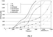
- FIGS. 1 and 2 illustrate the correlations between plasma HTP, H and temperature for argon and N 2 based plasmas with input data taken from the literature, such as Thermal Plasmas: Fundamentals and Applications, Volume 1, Boulos, Facuhais, Pfender, Plunum Press, New York (1994)("Thermal Plasmas”).
- Thermal Plasmas Fundamentals and Applications, Volume 1, Boulos, Facuhais, Pfender, Plunum Press, New York (1994)("Thermal Plasmas”
- plasma temperature corresponding to a particular HTP and related enthalpy may be significantly lower than plasma temperatures corresponding to argon-based plasmas under the same conditions. This is due to the energy needed for the molecule dissociation.
- argon based plasmas may have temperatures exceeding 9000°K while nitrogen based plasmas temperature may be below 7000°K (see Figures 1 and 2 ).
- CO 2 and Air plasmas may have even slightly higher HTP in comparison with N 2 plasma at the same plasma temperature.
- HTP may decrease significantly downstream of the anode arc root attachment plasma jet due to plasma radiation as well as plasma mixing/interaction with ambient air downstream of the nozzle exit. Decreasing of HTP may result in decreasing of feedstock active dwell time t d when HTP value is sufficient for effective heat transfer from plasma to the feedstock. Intensity of plasma interaction with ambient air may be controlled by plasma velocity including velocity distribution as well as by radial and tangential components of plasma velocity.
- N 2 based plasmas may provide significantly higher HTP at the same temperatures utilized for Argon.
- N 2 -H 2 plasma having 20 vol.% of H 2 may provide HTP up to 18 kW/m before plasma temperatures may achieve T ⁇ 9000-10000°C and the radiation may dominate in the energy balance thus resulting in extremely fast decrease of HTP.
- plasmas based on other molecular gases like Air and CO 2 may be stated regarding plasmas based on other molecular gases like Air and CO 2 .
- Table 1 Plasma HTP and Enthalpy corresponding to 9,000-10,000K plasma temperature for argon and nitrogen based plasmas Plasma gas (vol.
- GB 1 309 665 discloses a liquid stabilised plasma generator.
- US 2006/108332 A1 discloses a plasma spray coating system.
- a first aspect of the present invention provides a method for depositing a coating from a plasma torch.
- the present disclosure relates to systems and methods of plasma spraying and plasma treatment of materials based on high specific energy plasma gases.
- the present invention provides specific power molecular gas based plasmas with 140 kJ/g > SP >43 kJ/g which may also improve heat transfer to feedstock and, consequently, improve deposit quality and overall process efficiency.
- the specific power molecular gas based plasmas herein may include those with SP up to 120-140 kJ/g. Levels higher than 140 kJ/g even for nitrogen - hydrogen plasmas may result in plasma temperatures above 9,000-10,000K and all additional SP may be radiated.
- N 2 , air and CO 2 based plasmas are the preferred molecular gases herein. However, N 2 based plasmas may be most preferred as they may not generate free oxygen in the plasma jet and result in some undesirable outcomes like relatively intensive oxidation of metallic alloys during spraying.
- FIG. 3 illustrates a schematic illustrate of plasma system for modification and optimization herein.
- the plasma system 2 may generally be based on a plasma torch 4.
- the plasma system 2 may include a variety of modules.
- the plasma system 2 schematically depicted in FIG.3 may include a DC power source module (PS); control module (CT), which may control plasma gases flow rates, the plasma current and voltage, sequence of events during plasma start up and shut down, etc.; plasma ignition module (IG) and ignition circuit 16.
- the plasma torch 4, for performing the method of the present invention itself includes a cathode module C having at least one cathode 122; an inter-electrode inserts module (IEI) expanding and stabilizing the arc; and an anode module (A).
- PS DC power source module
- CT control module
- IG plasma ignition module
- the plasma torch 4, for performing the method of the present invention itself includes a cathode module C having at least one cathode 122; an inter-electrode inserts module (IEI) expanding
- Inter-electrode inserts module includes a Pilot Insert (PI), and at least one neutral inter-electrode insert (NI).
- a plasma jet forming module (F) is located downstream of anode arc root attachment for shaping and/or controlling the velocity and temperature of a plasma jet (PJ) exiting the torch.
- the forming means may be arranged as a separate module electrically insulated from anode module (A) in this case.
- the plasma jet forming means (F) may be also angled, which may provide the possibility of spraying on internal surface of parts and inside other confined spaces.
- a Feedstock Feeding module (FF) may be provided for introducing a material feedstock into a plasma jet (PJ) of plasma generated by the plasma torch 4.
- the Feedstock Feeding module may be located downstream of anode arc root attachment and may feed feedstock into a forming means (position 6 ) or into a plasma jet (position 8 ).
- Material feedstock may be in a form of powder. It may also be in a form of liquid precursor or suspension of fine powders in liquids like ethanol or water. Solid feedstock like wire, rod, and flexible cord may be used as well.
- a plasma gas flow G1 is supplied to the cathode area, i.e. a space formed between the cathode 122 and pilot insert PI, through a passage inside the cathode module C.
- Gp G1.
- a second plasma gas flow G2 is also used to generate the plasma.
- the second plasma gas flow G2 is supplied through a passage located between IEI module and Anode module as shown on FIG.3 .
- Still further additional plasma gasses may also be used to form the plasma.
- Such additional plasma gases may be supplied through passages formed in and/or between inter-electrode inserts.
- a third plasma gas flow G3 may also be used to generate plasma.
- G1, G2 and the additional gases may also reduce erosion of electrodes and inserts, undesirable possible arcing between various modules, pilot and neutral inserts and/or minimize erosion of electrodes, control plasma composition, etc. It may be noted that implementation of G3 and other possible additional plasma gases may result in the minor advantages dealing with the torch performance, however resulting in the torch design complexity and related maintenance and service challenges.
- the cathode 122 may be connected to a negative terminal of a DC power source PS.
- the DC power source may produce low ripple current, which may increase the stability of plasma parameters.
- a very low ripple may be achieved, for example, by using a ripple cancellation technique.
- An example may be DC power sources ESP-600C or EPP-601 manufactured by ESAB.
- the positive terminal of the power source may be connected to the pilot insert PI through the ignition circuit 16.
- the ignition circuit 16 may include the ignition module IG, resistor 18, switch 14, control elements, capacitors, choke, and inductors (not shown).
- the ignition module IG may have a high voltage, high frequency oscillator.
- the oscillator may initiate a pilot electrical arc 10 between the cathode 122 and the pilot insert PI.
- the DC power source PS may be employed to support the pilot arc 10.
- the pilot arc 10 may ionize at least a portion of the gases in a passage 26 formed by sub-passages which may have different diameter for passage of plasma. That is, pilot insert PI may be of one diameter, neutral inserts (NI) may have other diameters, and the anode may define a particular diameter for plasma passage.
- NI neutral inserts
- the low resistance path formed by ionized gas may allow initiation of a main arc 12 in an arc passage 26 between cathode 122 and anode module A.
- the switch 14 may be disengaged after the main arc 12 has been established, thus interrupting the pilot arc 10.
- several switches may be connected to inter-electrode inserts to generate arcs between the cathode 122 and the inter-electrode inserts connected to the switches.
- the arcs between the cathode 122 and the inter-electrode inserts may provide a low resistance path to facilitate initiation of the main arc 12, in the event that the length of the main arc 12 is greater than the capability of the ignition circuit utilizing only pilot insert PI.
- Plasma arc passage 26 may have different arrangements and options.
- Plasma passage inside PI may have diameter Dp and length Lp.
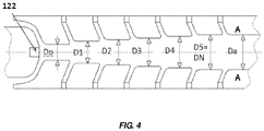
- FIG. 4 shows diameters Dp, D 1 , D 2 , D 3 , D 4 , D 5 up to DN.
- Plasma passages inside a neutral insert number "i" may therefore be designated to diameter D(i) and length Li.
- Dp may be the same or smaller than diameter D(1) of the adjacent (downstream) insert.
- Diameters of all neutral inserts (NI) may be the same as depicted on FIG. 3 .
- Diameters of neutral inserts may also increase downstream providing D(i+1) ⁇ D(i) as illustrated on FIG. 4 .
- the present disclosure now controls plasma passage diameter and profiles at the same plasma gases flow rates, SP and enthalpy which may now be a particularly effective tool to control plasma velocity separately of plasma temperature.
- expanding diameter of plasma passage providing larger diameter of an anode may result in relatively lower plasma velocity in comparison with a cylindrical plasma passage having a relatively smaller anode diameter.
- Plasma velocity and related feedstock dwell time control may be very beneficial when different size of particles of the same material are needed to achieve different properties if deposits.
- the plasma torch 4 may be capable of using a relatively high-voltage, relatively low current approach, which may suitably be used with a wide range of plasma gas flow rates, related SP, HTP and plasma velocity. Such a plasma torch may also be capable of realizing laminar, transition, and turbulent plasma jet flows. Generally, the plasma torch 4 may operate in a wide range of plasma current (e.g. 150 amps - 500 amps). Consequently, the method of the present invention is performed at currents lower than 500 A.
- plasma current e.g. 150 amps - 500 amps
- the length of arc (La) and related voltage values and their variations may depend on stability of arc in the area adjacent to cathode and inside IEI module, total length of IEI module as well as position of anode arc root attachment (15) inside anode. See FIG. 3 .
- Length of the IEI module may depend on the amount of neutral inserts (NI) and their thickness (5.0 mm - 25.0 mm).
- Position of anode arc root attachment may have axial instability and fluctuations due to arc shunting, which may result in undesirable voltage fluctuations and related instability of plasma jet parameters.
- the present invention is therefore, now capable of generating plasmas with SP>43 kJ/g using gases having more than 50 vol.% of molecular gases. Such may then provide:
- plasma current may be preferably at or below 500 A, and in the range of 150A to 500A.
- the current value of the present invention is lower than 500 A.
- Such current levels may provide relatively long life of the electrodes.
- the most preferable range of current is 200-400A.
- At current above 500A even high efficiency gas swirls may not provide sufficient rotation of anode arc root needed to control the heat flux especially to anode.
- electro-magnetic means to rotate the arc may be needed to provide long life of a torch at current above 500A.
- Voltage control may be done most preferably by controlling the arc length which depends on the total length of the IEI module. Additional less preferred voltage control may be also used. For example, relatively smaller diameter of plasma passages formed by a pilot insert and/or neutral inserts may result in relatively higher voltage.
- the stability of the arc in the area adjacent to cathode and inside IEI module may be achieved by providing G1 having a tangential component of velocity, thus creating vortex in the area located between the cathode and pilot insert.
- the vortex may propagate downstream along plasma arc area thus may cause stabilizing of the arc additionally to wall stabilization by IEI.
- the G1 flow rate is more than 60 vol% of total plasma gas flow rate, which means G1>0.6Gp, to preferably support the vortex propagation along the plasma channel inside the IEI module. See again, FIG. 3 .
- the above disadvantage may now be minimized or completely avoided in accordance with the present invention by providing G2 with a tangential component of the gas velocity providing the same rotation direction as G1, which occurs before the anode arc root attachment. Positive effect of G2 addition to G1 may be observed from some minimum value G2,min.
- Minimum vortex intensity related to G2 may be on the same level as for G1, i.e. Vort2 > 0.1 g/(sec*mm2). However, G2 flow is lower than 0.4 Gp which follows from G1>0.6Gp.
- the techniques to feed G2 into the plasma channel may be preferably located relatively close to the anode arc root attachment, preferably 3-25 mm upstream of the arc root attachment. Thus, by feeding G2 close to the anode arc root attachment, a minimum or no decrease of vortex intensity in the area of arc root attachment may be expected which may result in relatively long life of an anode.
- transition zone 24 in the plasma passage between IEI module and cylindrical part of an anode with simultaneous positioning of G2 vortex feeding methods inside the transition zone. This may result in further decrease of the arc instability and pulsing within wide range of operating parameters including parameters providing specific power SP>43 kJ/g.
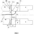
- Figure 5 illustrates one of the preferred embodiments of the transition zone 24 which may include an expansion 30 downstream of the end of plasma passage 26 inside of the IEI module.
- the expansion 30 may therefore be configured such that a discontinuity occurs in the passage 26 thereby causing a distortion in the plasma flow.
- the flow of plasma is distorted due to the feature that the zone 24 includes an expansion surface 24a to provide a diameter increase in the plasma passage.
- a ceramic ring insulator 28 is positioned in a slot 24b between the IEI module and the anode module A.
- the anode has an entrance zone 24c and cylindrical portion 44 and diameter Da associated with cylindrical portion 44.
- Slot 24b may be approximately 1.5-3 mm wide and may as noted contain the ceramic ring 28 insulating the IEI module from the anode module.
- G2 swirl plasma gas may be fed in zone 24b (G2-b) and/or in zone 24c (G2-c) which is illustrated in FIGS. 5-6 .
- the anode entrance zone may have different geometric shapes. For example, FIG. 6 illustrates a conical portion 46 of entrance zone 24c while FIG. 5 illustrates a rounded entrance zone 24c.
- G2 orifices may locate on diameter D(G2) illustrated in FIGS. 5-6 which preferably are at least 2-3 mm larger than anode diameter Da.
- anode arc root attachment locates preferably near or on the upstream portion of the cylindrical portion 44 of the anode.
- the maximum observed downstream position of anode arc root attachment may be preferably characterized by Lc which is illustrated in FIG. 5 .
- Lc ⁇ (1-1.5) Da .
- FIG. 4 illustrates one of possible plasma passage profiles which may be used to realize independent plasma velocity control.
- Symbol DN may be also used for the diameter of the last downstream insert of IEI module which is adjacent to an anode (insert #5 on FIG. 4 ).
- the velocity of plasma exiting an anode may be approximately proportional to 1 / (anode surface area), i.e. V ⁇ 1/Da 2 .
- the following data regarding the rate of velocity control ( ⁇ ) and related parameters were obtained based on a plasma torch used for the methods herein.
- Effective plasma arc stabilization and anode arc root rotation by swirls G1 and G2 disclosed above may result in the high relative intensity swirling flow of the plasma jet downstream of the anode arc root attachment.
- a relatively excessive tangential component of the velocity of the plasma jet may consequently result in excessive mixing of plasma jet with ambient air, related shortening of high HTP core part of plasma jet and decreasing of active feedstock dwell time td as well as resulting decreasing of efficiency of feedstock treatment in the plasma jet.
- the minimized tangential component may then result in relatively minimized mixing (interaction) of the plasma jet with surrounding media (air) and, consequently, relatively longer high temperature maintenance of the jet and relatively longer active dwell time.
- a relatively minimized tangential component may also result in better controllable feedstock injection into desirable areas of plasma jet and, thus, better deposit quality and deposit efficiency.
- Different additional requirements to plasma jet parameters may also request additional different configurations of a forming nozzle.
- Abrupt stepped expansion of the plasma jet passage diameter from Da to Ds with a following cylindrical plasma jet passage having diameter D S >Da may be an efficient way of decreasing the plasma tangential component.
- This expansion may be characterized by step angle ⁇ , expansion ratio ⁇ , and expansion angle ⁇ which is illustrated by FIG. 7 .
- Step angle ⁇ may be of about 90° with acceptable variations of about +/-10°. Generally, it may be expected that higher jet expansion angle ⁇ and larger expansion rate may result in lower tangential component of velocity of plasma jet exiting the forming nozzle.
- jet expansion angle ⁇ >25° may also result in the shortening of plasma jet which may be explained by a significant amount of ambient air which may penetrate inside the over expanded nozzle and have a negative influence on the jet formation.
- decreasing of the expansion angle ⁇ ⁇ 8° may not result in sufficient decreasing of the plasma velocity tangential component. However, it may result in the increasing of the nozzle length and, therefore, it may result in additional heat losses due to the heat exchange between the nozzle wall and plasma.
- a positive effect of the swirl decreasing may be expected within the preferred range 8°> ⁇ >25°. The most pronounced effect may be observed within ⁇ ⁇ 10-18°.
- Optimum expansion ratio ⁇ may be understood as 0.2 Da ⁇ ⁇ ⁇ 0.6 Da. At ⁇ ⁇ 0.2 Da decreasing of the tangential component may be relatively insignificant or even may not be observed. At ⁇ ⁇ 0.6 Da further decreasing of the tangential component was not observed. However, further increasing of the related nozzle length may result in the increasing of heat losses already described above. It may be noted that such a stepped expansion of the plasma passage may also result in equalizing of plasma jet temperature and velocity across the jet profile which may result in further improvement of homogeneity of treatment of feedstock powders or suspension, etc, high deposit efficiency and deposit quality.
- the stepped expansion of the plasma jet passage may be located under angle ⁇ to the anode axis which illustrated by FIG. 8 .
- Angle ⁇ may vary within 0-90° based on a technology requirements. Generally, ⁇ may preferably be within 45°-80°.
- feedstock feeding options may be utilized by the method which is illustrated on FIGS. 7 and 8 (positions 6a-6c, 8 ).
- the stepped expansion of plasma jet passage downstream of an anode arc root attachment may be used for other plasma spray processes / torches and not the plasma jet configurations specifically described herein. In this case the expansion may be arranged at a distance of about (1-2) Da downstream of arc root preferable attachment area.
- Feeding of additional gases into the stepped expansion may also assist formation of a desirable plasma jet parameters and further decrease the tangential component of plasma velocity.
- FIG. 9 illustrates an option when additional gases may be fed through multiple gas passages 32 located axially to plasma jet.
- FIG. 10 illustrates radial gas passages 34 for feeding of additional gases and providing them with a swirl which may have a direction contrary to the plasma jet swirl generated by G1 and G2.
- a plasma apparatus consistent with the present disclosure may generate a plasma jet having a high specific power and temperature.
- high plasma temperature and specific power may result in undesirable overheating a substrate being spray coated with the plasma apparatus. For example, it may happen when short spray distance must be used for spraying due to a confined space.
- Overheating of the substrate may produce stress in the coating and/or defects related to agglomeration of fine particles, e.g., having a size below about 5-10 micrometers, as well as various other defects. Generally, such defects may be described as "lamps" or "bumps".
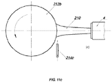
- a compressed gas deflection jet may be applied across the plasma jet 210 containing feedstock by a deflection gas nozzle 214a.
- the gas nozzle 214a may be disposed outside of the spray pattern generated by the plasma apparatus 4 and may be directed generally parallel to the substrate 212a, and/or at a slight angle thereto, in the region of the spray pattern or above it.
- the nozzle 214a may be positioned just outside of the spray pattern, while in other embodiments the nozzle 214a may be located further away from the spray pattern.
- Different configurations for locating the nozzle 214a and 214c are illustrated in FIGS. 11a , and 11c .
- the deflection gas nozzle 214 may have a generally rectangular profile, as depicted in FIG. 11b .
- the nozzle 214 may be wider than the spray pattern produced by the plasma apparatus 4.
- the nozzle 214 may have a width in the range of about 30-50 mm for a spray pattern in the order of 25 mm wide.
- the height h of the nozzle 214b may be in the range of about 1-4 mm.
- the compressed gas of the deflection jet may be air, nitrogen, etc., and may be supplied at a pressure on the general order of around 3-6 bars.
- the deflection gas jet may deflect the plasma jet 210 generated by the plasma torch 4, along with any fine particles, for example particle having a size less than about 5-10 microns. Larger particle may have sufficient mass, and therefore inertia, to pass through the deflection jet without being substantially deflected.
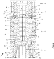
- Cathode Module C may have a cathode base 124 with cathode insert 122, cathode housing 128, cathode holder 144, cathode nut 132, and cathode vortex distributor 126.
- Cathode base 124 may be made of high conductivity material, e.g. copper or copper alloy.
- Cathode base 124, cathode 122 and cathode nut 132 may have electrical contact with cathode holder 144.
- Cathode holder 144 may be connected to a negative terminal of a DC power source shown on FIG.3 .
- Pilot insert 80 may have an electrical contact 86 with cathode housing 128 which during ignition may be connected to a positive terminal of a DC through a resistor 18 and switch 14 shown on Fig.3 .
- Cathode housing 128 and cathode holder 144 may be electrically insulated from each other by cathode insulator 152
- Cathode housing may have a gas passage 130 to feed G1 portion of a plasma gas.
- the gas passage 130 may be connected with cathode vortex distributor 126 having a circular gas receiver 134 connected with radial multiple gas passages 146 which, in turn, are connected to corresponding axial passages 136.
- Each axial passage 136 may be connected with the vortex holes 138.
- Sealing O-rings 148 may be used to seal the gas passages.
- FIGS. 13 a-b illustrate additional features of an embodiment of cathode vortex distributor 126 having 6 holes.
- the amount of holes (more than 3 at a minimum) and their diameters may be used to control the vortex intensity Vort1 and to adjust it satisfying requirements disclosed above.
- this vortex distributor may be used for G1>0.3 g/sec.
- the G1 top limit depends on a sonic velocity as was mentioned above and may be estimated for each particular plasma gas. For example, at room temperature sonic velocity and density for nitrogen are about 334 m/sec and 1.165 kg/m3.
- range of nitrogen flow rate through surface area 3 mm 2 may be estimated at approximately 15-60 L/min.
- the vortex distributor 126 may be adjusted accordingly.
- An inter-electrode inserts module may consist of a pilot insert 80 and one or more neutral inserts.
- Four neutral inserts 81-84 may be used in the depicted embodiment. Inserts 81-84 may have the same diameter as shown on FIG. 12 . Diameters of neutral inserts may also increase downstream as shown on FIG. 4 providing plasma passage profile and related independent plasma velocity control.
- the neutral inserts may be electrically insulated from each other and from pilot insert 80 by a set of ceramic rings 88 and sealing O-rings 90.
- the amount of inserts may be changed providing different plasma voltage ranges and satisfying other possible requirements.
- only inserts 81 and 84 may be used in the embodiment if the torch length needs to be shortened.
- SP Specific Power
- a requirement to increase SP may be satisfied, for example, by use of 6 neutral inserts with related increasing of operating voltage up to about 240V and specific power up to about 110 kJ/g at the same current and N 2 flow rates.
- Anode module A may consist of anode housing 48 and anode 50.
- the anode may have an entrance converging zone 24c connecting with a cylindrical zone 44 having diameter Da.
- Transition zone 24 in the plasma passage between IEI module and cylindrical part 44 of the anode in this embodiment is formed by anode entrance zone 24c and an expansion zone 30 which is configured as a discontinuity in plasma passage 26.
- Downstream neutral insert 84 may have a circular lip 92 protruding into expansion zone 30 and having G2 vortex orifices 94 connected with circular gas distributor 54 and forming Vort2 in the transition zone.
- G2 plasma gas is fed into gas passage 52 located in anode housing 48 and connected with circular gas distributor 54 formed by ceramic ring insulator 28 and additional insulating ceramic ring 96. It may be noted that the position of vortex orifices may be changed for the anode entrance zone by just modification of ceramic rings 28 and 96.
- FIGS. 14 a-b illustrate more features of an embodiment of downstream neutral insert 84 having 6 vortex holes having diameter Dvor2.
- this vortex distributor may be used for gas flows G2 within 0.68 g/sec>G2> 0.17 g/sec.
- nitrogen flow rate in this case may be estimated within 8.6-34.5 L/min.
- a plasma forming means (F) in this embodiment are not electrically insulated from the anode and may include the abrupt stepped expansion 160 having diameter Ds. which may be located downstream of anode arc root attachment 15.
- the feedstock feeding module is not illustrated in FIG. 12 for clarity purposes. However, widely available powder injectors and powder injector holders manufactured by various third parties may be adopted for this embodiment.
- the torch generates unique extremely stable plasmas having specific power within 43-140 kJ/g having more than 50 vol.% of molecular gases.
- the plasmas may have specific powers of any one or more of the individual numerical value in this range, such as 43 kJ/g, 44 kJ/g, 45 kJ/g, 46 kJ/g, 47 kJ/g, etc.,48 kJ/g, 49 kJ/g, 50 kJ/g, 51 kJ/g, 52 kJ/g, 53 kJ/g, 54 kJ/g, 55 kJ/g, 56 kJ/g, 57 kJ/g, 58 kJ/g, 59 kJ/g, 60 kJ/g, 61kJ/g, 62kJ/g, 63 kJ/g, 64 kJ/g, 65 kJ
- reference to a stable plasma herein may be understood as: 1. No drifting or variations of average voltage above 1-2% of setup values during the life of the electrodes where the electrodes may have a lifetime of 30 hours, 40 hours, 50 hours, etc., depending upon the level of specific power; and (2) No high frequency (on kHz level) pulsing of plasma voltage of more than ⁇ 10 V.
- the method and apparatus described herein may be used to apply coatings on a variety of substrates. These may include, e.g, power generating components which may be understood as any component used in a device for the generation of powder. This may therefore include blades, vanes, combustors, liners, etc. One may also utilize the method and apparatus herein for coating of chambers which are used for application of vapor deposition materials.
- power generating components which may be understood as any component used in a device for the generation of powder. This may therefore include blades, vanes, combustors, liners, etc.
- One may also utilize the method and apparatus herein for coating of chambers which are used for application of vapor deposition materials.
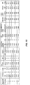
- Table 1 contents examples of parameters used to deposit different coatings based on the disclosed method and apparatus herein. High deposit efficiency as well as superior quality of coatings was observed. Some of the significant observations were as follows.
- Example 1 is related to Cr 2 O 3 coatings sprayed by a powder manufactured by HC Starck and demonstrated high microhardness of about HV 1400-1500.
- Example 2 is related to NiCrAlY coatings which demonstrated extremely low oxides content and permeability and, therefore, high corrosion resistance. It may be noted that application of a deflection jet in this case resulted in the further decreasing of oxides content and permeability.
- the deflection nozzle was 40 mm wide with a height of about 2.5 mm and was located 80 mm downstream of a powder injector. Compressed nitrogen at pressure of about 4 bars was used for the deflection jet. Spray distance was 110 mm.
- Examples 3-5 are related to thermal barrier porous coatings sprayed by spray-dry and sintered ZrO2-8%Y2O3 powder (ZRO-182 manufactured by Praxair). All coatings demonstrated pronounced porosity with average pores size of about 4-8 microns. Total porosity of the coatings was as follows: coating #3 - 28-30%; coating #4 - 33-35%; Coating #5 - 16-18%.
- Examples 6-7 are related to thermal barrier dense coatings having vertical cracks and sprayed by fused and crashed powder PC-YZ8t manufactured by St.Gobain. It may be noted that coating #7 demonstrated higher density of vertical cracks due to higher specific powers.
- thermal barrier coating may consist of a metallic bond coat (BC) and ceramic top coat (TC) and each of them may have multiple layers sprayed by multiple plasma torch passes.
- Each layer may generally have a thickness of about 10-50 microns.
- total coating having thickness for example, 500 microns may be sprayed by 10-50 passes and has, consequently 10-50 layers.
- high SP molecular plasmas may be needed only to spray some layers.
- SP> 43 kJ/g may be needed only to spray first layer or layers of a BC providing a good bonding and interface with a substrate.
- Another example may be TC coating having a pronounced porosity and sprayed by big ceramic particles having average size 60-100 microns which may also need SP>43 kJ/g.
- some layers may be sprayed by different methods.
- some BC layers may be sprayed by Low Pressure Plasma Spraying (LPPS) or by High Velocity Oxygen Fuel (HVOF) processes.
- LPPS Low Pressure Plasma Spraying
- HVOF High Velocity Oxygen Fuel
Landscapes
- Engineering & Computer Science (AREA)
- Physics & Mathematics (AREA)
- Plasma & Fusion (AREA)
- Spectroscopy & Molecular Physics (AREA)
- Chemical & Material Sciences (AREA)
- Mechanical Engineering (AREA)
- Chemical Kinetics & Catalysis (AREA)
- Materials Engineering (AREA)
- Metallurgy (AREA)
- Organic Chemistry (AREA)
- Geometry (AREA)
- Plasma Technology (AREA)
- Coating By Spraying Or Casting (AREA)
Claims (10)
- Procédé destiné à déposer un revêtement à partir d'une torche à plasma (4) à une tension (U) supérieure à 100 V et un courant (I) inférieur à 500 A, dans lequel la torche à plasma comprend :un module de cathode (C) comportant une électrode de cathode (122), un module d'anode (A) présentant une électrode d'anode et un axe d'anode, une zone d'entrée (24c) et une zone cylindrique (44) de diamètre Da ;dans lequel ladite torche à plasma (4) génère un arc de plasma présentant une fixation de racine d'arc d'anode (15) à l'intérieur dudit module d'anode (A) ;un module de formation de jet de plasma (F) situé en aval de ladite fixation de racine d'arc d'anode (15), ledit module de formation de jet de plasma (F) commandant un ou plusieurs paramètres d'un jet de plasma (PJ) formé dans ledit module ;un module interélectrodes (IEI) commandant un passage d'arc de plasma (26) entre ledit module de cathode (C) et ledit module d'anode (A) et présentant une extrémité adjacente audit module de cathode (C) et une seconde extrémité adjacente audit module d'anode (A) et présentant un insert pilote (PI) adjacent audit module de cathode (C) ;au moins un insert interélectrodes neutre (NI) ;ladite torche à plasma (4) comprenant en outre deux passages pour alimenter du gaz de plasma à un débit total Gp, dans lequel ledit gaz de plasma comprend plus de 50 % en volume de gaz moléculaire ;dans lequel l'un desdits passages destinés à alimenter ledit gaz de plasma comprend un premier passage de gaz de plasma situé entre ladite électrode de cathode (122) et ledit insert pilote (PI) destiné à alimenter du gaz de plasma à un premier débit G1 ;dans lequel ledit gaz de plasma au débit G1 est dirigé à travers une pluralité d'orifices présentant une superficie S1 ;dans lequel un vortex est formé, présentant une intensité de vortex Vort1 = G1/S1 ;dans lequel l'un desdits passages destinés à alimenter ledit gaz de plasma comprend un second passage de gaz de plasma situé entre ledit module interélectrodes et ladite zone cylindrique (44) du module d'anode (A) destiné à alimenter le gaz de plasma à un second débit G2 ;dans lequel ledit gaz de plasma à un second débit G2 est dirigé à travers une pluralité d'orifices (94) présentant une superficie S2 ;dans lequel un vortex est formé, présentant une intensité de vortex Vort2 = G2/S2 ;le procédé comprenant la fourniture d'une charge d'alimentation dans ledit jet de plasma et le dépôt d'un revêtement sur un substrat (212a) ;le procédé caractérisé en ce que G1 est supérieur à 0,6 Gp et Vort1 = G1/S1 est supérieur à 0,1 g/(sec[mm2]) ;et en ce que (U)(I)/(Gp) est dans la plage de 43 kJ/g à 140 kJ/g.
- Utilisation d'une torche à plasma (4) destinée à réaliser le procédé selon la revendication 1, dans laquelle la torche à plasma (4) comprend :un module de cathode (C) comportant une électrode de cathode (122), un module d'anode (A) présentant une électrode d'anode et un axe d'anode, une zone d'entrée (24c) et une zone cylindrique (44) de diamètre Da ;dans laquelle ladite torche à plasma (4) génère un arc de plasma présentant une fixation de racine d'arc d'anode (15) à l'intérieur dudit module d'anode (A) ;un module de formation de jet de plasma (F) situé en aval de ladite fixation de racine d'arc d'anode (15), ledit module de formation de jet de plasma (F) commandant un ou plusieurs paramètres d'un jet de plasma (PJ) formé dans ledit module ;un module interélectrodes (IEI) commandant un passage d'arc de plasma (26) entre ledit module de cathode (C) et ledit module d'anode (A) et présentant une extrémité adjacente audit module de cathode (C) et une seconde extrémité adjacente audit module d'anode (A) et présentant un insert pilote (PI) adjacent audit module de cathode (C) ;au moins un insert interélectrodes neutre (NI) ;ladite torche à plasma (4) comprenant en outre deux passages pour alimenter ledit gaz de plasma à un débit total Gp, ledit gaz de plasma comprenant plus de 50 % en volume de gaz moléculaire ;dans laquelle l'un desdits passages destinés à alimenter ledit gaz de plasma comprend un premier passage de gaz de plasma situé entre ladite électrode de cathode (122) et ledit insert pilote (PI) destiné à alimenter le plasma à un premier débit G1 ;dans laquelle ledit gaz de plasma au débit G1 est dirigé à travers une pluralité d'orifices présentant une superficie S1 ;dans laquelle un vortex est formé, présentant une intensité de vortex Vort1 = G1/S1 ;dans laquelle l'un desdits passages destinés à alimenter ledit gaz de plasma comprend un second passage de gaz de plasma situé entre ledit module interélectrodes et ladite zone cylindrique (44) du module d'anode (A) destinée à alimenter du gaz de plasma à un second débit G2 ;dans laquelle ledit gaz de plasma au second débit G2 est dirigé à travers une pluralité d'orifices (94) présentant une superficie S2 ;dans laquelle un vortex est formé, présentant une intensité de vortex Vort2 = G2/S2 ;dans laquelle G1 est supérieur à 0,6 Gp et Vort1 = G1/S1 est supérieur à 0,1 g/((sec)(mm2)) ; etdans laquelle (U)(I)/(Gp) est dans la plage de 43 kJ/g à 140 kJ/g ;dans laquelle ledit Vort2 est supérieur à 0,1 g/((sec)(mm2)) et inférieur à 0,4 g/((sec)(mm2)) et ladite pluralité d'orifices se situent sur un diamètre d'au moins 2 mm supérieur audit Da.
- Utilisation selon la revendication 2, dans laquelle ledit module interélectrodes (IEI) présente une pluralité desdits inserts interélectrodes neutres (NI), chacun présentant un diamètre, qui définit ledit passage d'arc de plasma (26).
- Utilisation selon la revendication 3, dans laquelle ladite pluralité d'inserts interélectrodes neutres (NI) fournit un passage d'arc de plasma (26) de diamètre croissant.
- Utilisation d'une torche à plasma selon la revendication 3, dans laquelle ladite pluralité d'inserts interélectrodes neutres (NI) définit un passage d'arc de plasma (26) de diamètre constant.
- Utilisation selon l'une quelconque des revendications 2 à 5, dans laquelle ledit module de formation de jet de plasma (F) présente une buse de formation fournissant une expansion échelonnée du passage de jet de plasma dudit diamètre Da au diamètre Ds et dans laquelle (Ds-Da)/2 est à l'intérieur de (0,2-0,6) Da, dans laquelle (0,2-0,6) Da = δ, dans laquelle δ est le rapport d'expansion.
- Utilisation selon la revendication 6, dans laquelle ladite expansion échelonnée est définie par ledit rapport d'expansion δ et un angle d'expansion α et α présente une valeur de 8° à 25 °.
- Utilisation selon la revendication 6, dans laquelle ladite expansion échelonnée est positionnée dans la plage de 45 ° et 80 ° dudit axe d'anode.
- Utilisation selon l'une quelconque des revendications 2 à 8, comprenant la fourniture d'une charge d'alimentation dans ledit jet de plasma (PJ).
- Utilisation selon la revendication 8, dans laquelle un jet de déflexion de gaz comprimé est appliqué sur toute l'étendue dudit jet de plasma (PJ) comprenant ladite charge d'alimentation.
Applications Claiming Priority (3)
| Application Number | Priority Date | Filing Date | Title |
|---|---|---|---|
| US201261608426P | 2012-03-08 | 2012-03-08 | |
| US13/771,908 US9150949B2 (en) | 2012-03-08 | 2013-02-20 | Plasma systems and methods including high enthalpy and high stability plasmas |
| PCT/US2013/029814 WO2013134619A1 (fr) | 2012-03-08 | 2013-03-08 | Systèmes et procédés à plasma comprenant des plasmas d'enthalpie élevée et de stabilité élevée |
Publications (3)
| Publication Number | Publication Date |
|---|---|
| EP2822724A1 EP2822724A1 (fr) | 2015-01-14 |
| EP2822724A4 EP2822724A4 (fr) | 2015-08-19 |
| EP2822724B1 true EP2822724B1 (fr) | 2020-11-25 |
Family
ID=49114354
Family Applications (1)
| Application Number | Title | Priority Date | Filing Date |
|---|---|---|---|
| EP13758351.4A Active EP2822724B1 (fr) | 2012-03-08 | 2013-03-08 | Procédé et utilisation d'une chalumeau à plasma pour le revêtement d'un substrat |
Country Status (4)
| Country | Link |
|---|---|
| US (2) | US9150949B2 (fr) |
| EP (1) | EP2822724B1 (fr) |
| JP (1) | JP6262670B2 (fr) |
| WO (1) | WO2013134619A1 (fr) |
Families Citing this family (26)
| Publication number | Priority date | Publication date | Assignee | Title |
|---|---|---|---|---|
| US10314155B2 (en) * | 2012-08-06 | 2019-06-04 | Hypertherm, Inc. | Asymmetric consumables for a plasma arc torch |
| US10721812B2 (en) | 2012-08-06 | 2020-07-21 | Hypertherm, Inc. | Asymmetric consumables for a plasma arc torch |
| TWI581671B (zh) * | 2013-11-05 | 2017-05-01 | Plasma torch device | |
| EP3143845A4 (fr) * | 2014-05-16 | 2018-03-14 | Pyrogenesis Canada Inc. | Torche à plasma haute puissance écoénergétique |
| JP6035438B1 (ja) * | 2016-01-05 | 2016-11-30 | 株式会社Helix | 渦水流発生器、水プラズマ発生装置、分解処理装置、分解処理装置搭載車両及び分解処理方法 |
| AU2016384478B2 (en) | 2016-01-05 | 2020-10-01 | Helix Co., Ltd. | Vortex water flow generator, water plasma generating device, decomposition treatment device, vehicle equipped with decomposition treatment device, and decomposition treatment method |
| CH712835A1 (de) * | 2016-08-26 | 2018-02-28 | Amt Ag | Plasmaspritzvorrichtung. |
| JP6668219B2 (ja) * | 2016-10-31 | 2020-03-18 | 株式会社Helix | 渦水流発生器、水プラズマ発生装置、分解処理装置、分解処理装置搭載車両及び分解処理方法 |
| KR20180061967A (ko) * | 2016-11-30 | 2018-06-08 | 한국수력원자력 주식회사 | 다중전극 플라즈마 토치 |
| KR102646623B1 (ko) * | 2017-01-23 | 2024-03-11 | 에드워드 코리아 주식회사 | 플라즈마 발생 장치 및 가스 처리 장치 |
| KR102686242B1 (ko) | 2017-01-23 | 2024-07-17 | 에드워드 코리아 주식회사 | 질소 산화물 감소 장치 및 가스 처리 장치 |
| US10612122B2 (en) * | 2017-08-25 | 2020-04-07 | Vladimir E. Belashchenko | Plasma device and method for delivery of plasma and spray material at extended locations from an anode arc root attachment |
| KR102110377B1 (ko) * | 2017-11-30 | 2020-05-15 | 한국수력원자력 주식회사 | 전방전극이 다중전극이면서 후방전극이 버튼형으로 구성된 플라즈마 토치 |
| RU2020129100A (ru) * | 2018-02-20 | 2022-03-21 | ЭРЛИКОН МЕТКО (ЮЭс) ИНК. | Однодуговой каскадный плазмотрон низкого давления, использующий пакет нейтродов как способ контроля плазменной дуги |
| KR20180062446A (ko) * | 2018-05-25 | 2018-06-08 | 한국수력원자력 주식회사 | 다중전극 플라즈마 토치 |
| KR102228888B1 (ko) * | 2019-01-21 | 2021-03-17 | 엘지전자 주식회사 | 열플라즈마 처리장치 |
| US12159768B2 (en) * | 2019-03-25 | 2024-12-03 | Recarbon, Inc. | Controlling exhaust gas pressure of a plasma reactor for plasma stability |
| KR102207933B1 (ko) * | 2019-07-17 | 2021-01-26 | 주식회사 그린리소스 | 서스펜션 플라즈마 용사 장치 및 그 제어 방법 |
| RU2762196C2 (ru) * | 2019-07-25 | 2021-12-16 | Федеральное государственное бюджетное образовательное учреждение высшего образования "Липецкий государственный технический университет" (ЛГТУ) | Электродуговой плазмотрон |
| WO2021118664A1 (fr) | 2019-09-13 | 2021-06-17 | Praxair S.T. Technology, Inc. | Procédés de production de revêtements améliorés à cristallinité et densité accrues |
| EP4044772A4 (fr) * | 2019-10-02 | 2023-06-21 | Korea Hydro & Nuclear Power Co., Ltd | Torche à plasma |
| CN110975538B (zh) * | 2019-11-09 | 2022-08-26 | 上海硕余精密机械设备有限公司 | 一种等离子炬、尾气处理系统 |
| RU2763161C1 (ru) * | 2021-04-15 | 2021-12-27 | Федеральное государственное бюджетное образовательное учреждение высшего образования "Липецкий государственный технический университет" (ЛГТУ) | Электродуговой плазмотрон для обработки поверхностей деталей |
| CN114236168A (zh) * | 2021-12-28 | 2022-03-25 | 中国航天空气动力技术研究院 | 电弧等离子体发生器弧根旋转速度测量装置及测量方法 |
| US12096547B1 (en) * | 2023-08-10 | 2024-09-17 | Vladimir E. Belashchenko | High velocity plasma torch and method |
| WO2025193650A1 (fr) * | 2024-03-14 | 2025-09-18 | Belashchenko Vladimir E | Torche à plasma à grande vitesse et procédé |
Citations (1)
| Publication number | Priority date | Publication date | Assignee | Title |
|---|---|---|---|---|
| US20060108332A1 (en) * | 2004-11-24 | 2006-05-25 | Vladimir Belashchenko | Plasma system and apparatus |
Family Cites Families (17)
| Publication number | Priority date | Publication date | Assignee | Title |
|---|---|---|---|---|
| CH494517A (de) * | 1969-06-10 | 1970-07-31 | Lonza Ag | Verfahren und Vorrichtung zur Stabilisierung des im Innern eines länglichen Flüssigkeitswirbels brennenden elektrischen Lichtbogens |
| US4841114A (en) | 1987-03-11 | 1989-06-20 | Browning James A | High-velocity controlled-temperature plasma spray method and apparatus |
| CA1323670C (fr) | 1988-05-17 | 1993-10-26 | Subramania Ramakrishnan | Reacteur a arc electrique |
| DE4105408C1 (fr) * | 1991-02-21 | 1992-09-17 | Plasma-Technik Ag, Wohlen, Ch | |
| US5317126A (en) * | 1992-01-14 | 1994-05-31 | Hypertherm, Inc. | Nozzle and method of operation for a plasma arc torch |
| JPH07130490A (ja) | 1993-11-02 | 1995-05-19 | Komatsu Ltd | プラズマトーチ |
| US6114649A (en) * | 1999-07-13 | 2000-09-05 | Duran Technologies Inc. | Anode electrode for plasmatron structure |
| JP4678973B2 (ja) * | 2001-03-29 | 2011-04-27 | 西日本プラント工業株式会社 | 溶射トーチのプラズマアークの発生装置及び発生方法 |
| US6861101B1 (en) | 2002-01-08 | 2005-03-01 | Flame Spray Industries, Inc. | Plasma spray method for applying a coating utilizing particle kinetics |
| US7608797B2 (en) * | 2004-06-22 | 2009-10-27 | Vladimir Belashchenko | High velocity thermal spray apparatus |
| WO2006012165A2 (fr) * | 2004-06-25 | 2006-02-02 | H.C. Starck Inc. | Appareil destine a generer un jet de plasma ainsi que procede d'utilisation associe |
| US7375302B2 (en) | 2004-11-16 | 2008-05-20 | Hypertherm, Inc. | Plasma arc torch having an electrode with internal passages |
| KR100807806B1 (ko) * | 2006-04-04 | 2008-02-27 | 제주대학교 산학협력단 | 직류 아크 플라즈마트론 장치 및 사용 방법 |
| WO2007121556A1 (fr) * | 2006-04-25 | 2007-11-01 | National Research Counsil Of Canada | Enduction par pulvérisation thermique d'une charge de départ céramique nanostructurée poreuse |
| CN101828432B (zh) * | 2007-08-06 | 2013-11-06 | 普拉斯马外科投资有限公司 | 用于生成脉冲等离子体的脉冲等离子体装置和方法 |
| CN101784154B (zh) * | 2009-01-19 | 2012-10-03 | 烟台龙源电力技术股份有限公司 | 电弧等离子体发生器的阳极以及电弧等离子体发生器 |
| WO2012088421A1 (fr) * | 2010-12-22 | 2012-06-28 | Flame-Spray Industries, Inc. | Procédé et appareil améliorés de projection thermique qui utilisent un arc fil transféré au plasma |
-
2013
- 2013-02-20 US US13/771,908 patent/US9150949B2/en active Active
- 2013-03-08 EP EP13758351.4A patent/EP2822724B1/fr active Active
- 2013-03-08 WO PCT/US2013/029814 patent/WO2013134619A1/fr not_active Ceased
- 2013-03-08 JP JP2014561145A patent/JP6262670B2/ja active Active
-
2015
- 2015-10-06 US US14/876,225 patent/US9376740B2/en active Active
Patent Citations (1)
| Publication number | Priority date | Publication date | Assignee | Title |
|---|---|---|---|---|
| US20060108332A1 (en) * | 2004-11-24 | 2006-05-25 | Vladimir Belashchenko | Plasma system and apparatus |
Non-Patent Citations (1)
| Title |
|---|
| V VALIN IUS ET AL: "Electric and thermal characteristics of the linear, sectional dc plasma generator", PLASMA SOURCES SCIENCE AND TECHNOLOGY, vol. 13, no. 2, 24 February 2004 (2004-02-24), GB, pages 199 - 206, XP055633786, ISSN: 0963-0252, DOI: 10.1088/0963-0252/13/2/002 * |
Also Published As
| Publication number | Publication date |
|---|---|
| JP6262670B2 (ja) | 2018-01-17 |
| JP2015513776A (ja) | 2015-05-14 |
| US20160024635A1 (en) | 2016-01-28 |
| WO2013134619A1 (fr) | 2013-09-12 |
| US9376740B2 (en) | 2016-06-28 |
| EP2822724A1 (fr) | 2015-01-14 |
| US20130236652A1 (en) | 2013-09-12 |
| EP2822724A4 (fr) | 2015-08-19 |
| US9150949B2 (en) | 2015-10-06 |
Similar Documents
| Publication | Publication Date | Title |
|---|---|---|
| EP2822724B1 (fr) | Procédé et utilisation d'une chalumeau à plasma pour le revêtement d'un substrat | |
| US7750265B2 (en) | Multi-electrode plasma system and method for thermal spraying | |
| US8389888B2 (en) | Plasma torch with a lateral injector | |
| CA2670256C (fr) | Appareil et systeme a plasma | |
| US10730063B2 (en) | Plasma transfer wire arc thermal spray system | |
| US10612122B2 (en) | Plasma device and method for delivery of plasma and spray material at extended locations from an anode arc root attachment | |
| WO2006012165A2 (fr) | Appareil destine a generer un jet de plasma ainsi que procede d'utilisation associe | |
| US20070248766A1 (en) | Method And Apparatus For Thermal Spray Coating | |
| RU2366122C1 (ru) | Плазмотрон для нанесения покрытий | |
| Chen et al. | Influence of Process Parameters and Feedstock Selection on Coating Microstructures with a Cascaded Plasma Torch | |
| US12096547B1 (en) | High velocity plasma torch and method | |
| Barbezat et al. | Triplex-a high performance plasma torch | |
| WO2025193650A1 (fr) | Torche à plasma à grande vitesse et procédé | |
| McDonald et al. | High Stability, High Enthalpy APS Process Based on Combined Wall and Gas Stabilizations of Plasma (Part 1: Process and Coatings Introduction) |
Legal Events
| Date | Code | Title | Description |
|---|---|---|---|
| PUAI | Public reference made under article 153(3) epc to a published international application that has entered the european phase |
Free format text: ORIGINAL CODE: 0009012 |
|
| 17P | Request for examination filed |
Effective date: 20141002 |
|
| AK | Designated contracting states |
Kind code of ref document: A1 Designated state(s): AL AT BE BG CH CY CZ DE DK EE ES FI FR GB GR HR HU IE IS IT LI LT LU LV MC MK MT NL NO PL PT RO RS SE SI SK SM TR |
|
| AX | Request for extension of the european patent |
Extension state: BA ME |
|
| DAX | Request for extension of the european patent (deleted) | ||
| RA4 | Supplementary search report drawn up and despatched (corrected) |
Effective date: 20150716 |
|
| RIC1 | Information provided on ipc code assigned before grant |
Ipc: C23C 4/00 20060101ALI20150710BHEP Ipc: H05H 1/42 20060101ALI20150710BHEP Ipc: C23C 4/12 20060101ALI20150710BHEP Ipc: B05D 1/08 20060101ALI20150710BHEP Ipc: H05H 1/34 20060101ALI20150710BHEP Ipc: B23K 10/02 20060101ALI20150710BHEP Ipc: B23K 9/00 20060101AFI20150710BHEP |
|
| STAA | Information on the status of an ep patent application or granted ep patent |
Free format text: STATUS: EXAMINATION IS IN PROGRESS |
|
| 17Q | First examination report despatched |
Effective date: 20191024 |
|
| GRAP | Despatch of communication of intention to grant a patent |
Free format text: ORIGINAL CODE: EPIDOSNIGR1 |
|
| STAA | Information on the status of an ep patent application or granted ep patent |
Free format text: STATUS: GRANT OF PATENT IS INTENDED |
|
| INTG | Intention to grant announced |
Effective date: 20200605 |
|
| GRAS | Grant fee paid |
Free format text: ORIGINAL CODE: EPIDOSNIGR3 |
|
| GRAA | (expected) grant |
Free format text: ORIGINAL CODE: 0009210 |
|
| STAA | Information on the status of an ep patent application or granted ep patent |
Free format text: STATUS: THE PATENT HAS BEEN GRANTED |
|
| AK | Designated contracting states |
Kind code of ref document: B1 Designated state(s): AL AT BE BG CH CY CZ DE DK EE ES FI FR GB GR HR HU IE IS IT LI LT LU LV MC MK MT NL NO PL PT RO RS SE SI SK SM TR |
|
| REG | Reference to a national code |
Ref country code: GB Ref legal event code: FG4D |
|
| REG | Reference to a national code |
Ref country code: CH Ref legal event code: EP |
|
| REG | Reference to a national code |
Ref country code: AT Ref legal event code: REF Ref document number: 1337718 Country of ref document: AT Kind code of ref document: T Effective date: 20201215 |
|
| REG | Reference to a national code |
Ref country code: DE Ref legal event code: R096 Ref document number: 602013074309 Country of ref document: DE |
|
| REG | Reference to a national code |
Ref country code: IE Ref legal event code: FG4D |
|
| REG | Reference to a national code |
Ref country code: CH Ref legal event code: NV Representative=s name: TR-IP CONSULTING LLC, CH |
|
| REG | Reference to a national code |
Ref country code: NL Ref legal event code: FP |
|
| REG | Reference to a national code |
Ref country code: AT Ref legal event code: MK05 Ref document number: 1337718 Country of ref document: AT Kind code of ref document: T Effective date: 20201125 |
|
| PG25 | Lapsed in a contracting state [announced via postgrant information from national office to epo] |
Ref country code: NO Free format text: LAPSE BECAUSE OF FAILURE TO SUBMIT A TRANSLATION OF THE DESCRIPTION OR TO PAY THE FEE WITHIN THE PRESCRIBED TIME-LIMIT Effective date: 20210225 Ref country code: PT Free format text: LAPSE BECAUSE OF FAILURE TO SUBMIT A TRANSLATION OF THE DESCRIPTION OR TO PAY THE FEE WITHIN THE PRESCRIBED TIME-LIMIT Effective date: 20210325 Ref country code: FI Free format text: LAPSE BECAUSE OF FAILURE TO SUBMIT A TRANSLATION OF THE DESCRIPTION OR TO PAY THE FEE WITHIN THE PRESCRIBED TIME-LIMIT Effective date: 20201125 Ref country code: RS Free format text: LAPSE BECAUSE OF FAILURE TO SUBMIT A TRANSLATION OF THE DESCRIPTION OR TO PAY THE FEE WITHIN THE PRESCRIBED TIME-LIMIT Effective date: 20201125 Ref country code: GR Free format text: LAPSE BECAUSE OF FAILURE TO SUBMIT A TRANSLATION OF THE DESCRIPTION OR TO PAY THE FEE WITHIN THE PRESCRIBED TIME-LIMIT Effective date: 20210226 |
|
| PG25 | Lapsed in a contracting state [announced via postgrant information from national office to epo] |
Ref country code: AT Free format text: LAPSE BECAUSE OF FAILURE TO SUBMIT A TRANSLATION OF THE DESCRIPTION OR TO PAY THE FEE WITHIN THE PRESCRIBED TIME-LIMIT Effective date: 20201125 Ref country code: BG Free format text: LAPSE BECAUSE OF FAILURE TO SUBMIT A TRANSLATION OF THE DESCRIPTION OR TO PAY THE FEE WITHIN THE PRESCRIBED TIME-LIMIT Effective date: 20210225 Ref country code: IS Free format text: LAPSE BECAUSE OF FAILURE TO SUBMIT A TRANSLATION OF THE DESCRIPTION OR TO PAY THE FEE WITHIN THE PRESCRIBED TIME-LIMIT Effective date: 20210325 Ref country code: LV Free format text: LAPSE BECAUSE OF FAILURE TO SUBMIT A TRANSLATION OF THE DESCRIPTION OR TO PAY THE FEE WITHIN THE PRESCRIBED TIME-LIMIT Effective date: 20201125 Ref country code: SE Free format text: LAPSE BECAUSE OF FAILURE TO SUBMIT A TRANSLATION OF THE DESCRIPTION OR TO PAY THE FEE WITHIN THE PRESCRIBED TIME-LIMIT Effective date: 20201125 Ref country code: PL Free format text: LAPSE BECAUSE OF FAILURE TO SUBMIT A TRANSLATION OF THE DESCRIPTION OR TO PAY THE FEE WITHIN THE PRESCRIBED TIME-LIMIT Effective date: 20201125 |
|
| REG | Reference to a national code |
Ref country code: LT Ref legal event code: MG9D |
|
| PG25 | Lapsed in a contracting state [announced via postgrant information from national office to epo] |
Ref country code: HR Free format text: LAPSE BECAUSE OF FAILURE TO SUBMIT A TRANSLATION OF THE DESCRIPTION OR TO PAY THE FEE WITHIN THE PRESCRIBED TIME-LIMIT Effective date: 20201125 |
|
| PG25 | Lapsed in a contracting state [announced via postgrant information from national office to epo] |
Ref country code: RO Free format text: LAPSE BECAUSE OF FAILURE TO SUBMIT A TRANSLATION OF THE DESCRIPTION OR TO PAY THE FEE WITHIN THE PRESCRIBED TIME-LIMIT Effective date: 20201125 Ref country code: SK Free format text: LAPSE BECAUSE OF FAILURE TO SUBMIT A TRANSLATION OF THE DESCRIPTION OR TO PAY THE FEE WITHIN THE PRESCRIBED TIME-LIMIT Effective date: 20201125 Ref country code: LT Free format text: LAPSE BECAUSE OF FAILURE TO SUBMIT A TRANSLATION OF THE DESCRIPTION OR TO PAY THE FEE WITHIN THE PRESCRIBED TIME-LIMIT Effective date: 20201125 Ref country code: SM Free format text: LAPSE BECAUSE OF FAILURE TO SUBMIT A TRANSLATION OF THE DESCRIPTION OR TO PAY THE FEE WITHIN THE PRESCRIBED TIME-LIMIT Effective date: 20201125 Ref country code: CZ Free format text: LAPSE BECAUSE OF FAILURE TO SUBMIT A TRANSLATION OF THE DESCRIPTION OR TO PAY THE FEE WITHIN THE PRESCRIBED TIME-LIMIT Effective date: 20201125 Ref country code: EE Free format text: LAPSE BECAUSE OF FAILURE TO SUBMIT A TRANSLATION OF THE DESCRIPTION OR TO PAY THE FEE WITHIN THE PRESCRIBED TIME-LIMIT Effective date: 20201125 |
|
| REG | Reference to a national code |
Ref country code: DE Ref legal event code: R097 Ref document number: 602013074309 Country of ref document: DE |
|
| PG25 | Lapsed in a contracting state [announced via postgrant information from national office to epo] |
Ref country code: DK Free format text: LAPSE BECAUSE OF FAILURE TO SUBMIT A TRANSLATION OF THE DESCRIPTION OR TO PAY THE FEE WITHIN THE PRESCRIBED TIME-LIMIT Effective date: 20201125 |
|
| PLBE | No opposition filed within time limit |
Free format text: ORIGINAL CODE: 0009261 |
|
| STAA | Information on the status of an ep patent application or granted ep patent |
Free format text: STATUS: NO OPPOSITION FILED WITHIN TIME LIMIT |
|
| PG25 | Lapsed in a contracting state [announced via postgrant information from national office to epo] |
Ref country code: MC Free format text: LAPSE BECAUSE OF FAILURE TO SUBMIT A TRANSLATION OF THE DESCRIPTION OR TO PAY THE FEE WITHIN THE PRESCRIBED TIME-LIMIT Effective date: 20201125 Ref country code: AL Free format text: LAPSE BECAUSE OF FAILURE TO SUBMIT A TRANSLATION OF THE DESCRIPTION OR TO PAY THE FEE WITHIN THE PRESCRIBED TIME-LIMIT Effective date: 20201125 |
|
| 26N | No opposition filed |
Effective date: 20210826 |
|
| PG25 | Lapsed in a contracting state [announced via postgrant information from national office to epo] |
Ref country code: ES Free format text: LAPSE BECAUSE OF FAILURE TO SUBMIT A TRANSLATION OF THE DESCRIPTION OR TO PAY THE FEE WITHIN THE PRESCRIBED TIME-LIMIT Effective date: 20201125 Ref country code: SI Free format text: LAPSE BECAUSE OF FAILURE TO SUBMIT A TRANSLATION OF THE DESCRIPTION OR TO PAY THE FEE WITHIN THE PRESCRIBED TIME-LIMIT Effective date: 20201125 |
|
| REG | Reference to a national code |
Ref country code: BE Ref legal event code: MM Effective date: 20210331 |
|
| PG25 | Lapsed in a contracting state [announced via postgrant information from national office to epo] |
Ref country code: IE Free format text: LAPSE BECAUSE OF NON-PAYMENT OF DUE FEES Effective date: 20210308 Ref country code: LU Free format text: LAPSE BECAUSE OF NON-PAYMENT OF DUE FEES Effective date: 20210308 |
|
| PG25 | Lapsed in a contracting state [announced via postgrant information from national office to epo] |
Ref country code: IS Free format text: LAPSE BECAUSE OF FAILURE TO SUBMIT A TRANSLATION OF THE DESCRIPTION OR TO PAY THE FEE WITHIN THE PRESCRIBED TIME-LIMIT Effective date: 20210325 |
|
| PG25 | Lapsed in a contracting state [announced via postgrant information from national office to epo] |
Ref country code: BE Free format text: LAPSE BECAUSE OF NON-PAYMENT OF DUE FEES Effective date: 20210331 |
|
| PG25 | Lapsed in a contracting state [announced via postgrant information from national office to epo] |
Ref country code: HU Free format text: LAPSE BECAUSE OF FAILURE TO SUBMIT A TRANSLATION OF THE DESCRIPTION OR TO PAY THE FEE WITHIN THE PRESCRIBED TIME-LIMIT; INVALID AB INITIO Effective date: 20130308 |
|
| P01 | Opt-out of the competence of the unified patent court (upc) registered |
Effective date: 20230523 |
|
| PG25 | Lapsed in a contracting state [announced via postgrant information from national office to epo] |
Ref country code: CY Free format text: LAPSE BECAUSE OF FAILURE TO SUBMIT A TRANSLATION OF THE DESCRIPTION OR TO PAY THE FEE WITHIN THE PRESCRIBED TIME-LIMIT Effective date: 20201125 |
|
| PG25 | Lapsed in a contracting state [announced via postgrant information from national office to epo] |
Ref country code: MK Free format text: LAPSE BECAUSE OF FAILURE TO SUBMIT A TRANSLATION OF THE DESCRIPTION OR TO PAY THE FEE WITHIN THE PRESCRIBED TIME-LIMIT Effective date: 20201125 |
|
| PG25 | Lapsed in a contracting state [announced via postgrant information from national office to epo] |
Ref country code: TR Free format text: LAPSE BECAUSE OF FAILURE TO SUBMIT A TRANSLATION OF THE DESCRIPTION OR TO PAY THE FEE WITHIN THE PRESCRIBED TIME-LIMIT Effective date: 20201125 |
|
| PG25 | Lapsed in a contracting state [announced via postgrant information from national office to epo] |
Ref country code: MT Free format text: LAPSE BECAUSE OF FAILURE TO SUBMIT A TRANSLATION OF THE DESCRIPTION OR TO PAY THE FEE WITHIN THE PRESCRIBED TIME-LIMIT Effective date: 20201125 |
|
| PGFP | Annual fee paid to national office [announced via postgrant information from national office to epo] |
Ref country code: CH Payment date: 20250401 Year of fee payment: 13 |
|
| REG | Reference to a national code |
Ref country code: CH Ref legal event code: U11 Free format text: ST27 STATUS EVENT CODE: U-0-0-U10-U11 (AS PROVIDED BY THE NATIONAL OFFICE) Effective date: 20260401 |
|
| PGFP | Annual fee paid to national office [announced via postgrant information from national office to epo] |
Ref country code: GB Payment date: 20260327 Year of fee payment: 14 |
|
| PGFP | Annual fee paid to national office [announced via postgrant information from national office to epo] |
Ref country code: DE Payment date: 20260327 Year of fee payment: 14 |
|
| PGFP | Annual fee paid to national office [announced via postgrant information from national office to epo] |
Ref country code: IT Payment date: 20260319 Year of fee payment: 14 |
|
| PGFP | Annual fee paid to national office [announced via postgrant information from national office to epo] |
Ref country code: NL Payment date: 20260326 Year of fee payment: 14 |
|
| PGFP | Annual fee paid to national office [announced via postgrant information from national office to epo] |
Ref country code: FR Payment date: 20260325 Year of fee payment: 14 |