EP2823146B1 - Procédé de contrôle de l'étanchéité du puits d'acces d'une cavité souterraine et dispositif de réduction de l'écoulement par convection et par diffusion - Google Patents
Procédé de contrôle de l'étanchéité du puits d'acces d'une cavité souterraine et dispositif de réduction de l'écoulement par convection et par diffusion Download PDFInfo
- Publication number
- EP2823146B1 EP2823146B1 EP13712161.2A EP13712161A EP2823146B1 EP 2823146 B1 EP2823146 B1 EP 2823146B1 EP 13712161 A EP13712161 A EP 13712161A EP 2823146 B1 EP2823146 B1 EP 2823146B1
- Authority
- EP
- European Patent Office
- Prior art keywords
- gas
- layer
- cavity
- test gas
- access hole
- Prior art date
- Legal status (The legal status is an assumption and is not a legal conclusion. Google has not performed a legal analysis and makes no representation as to the accuracy of the status listed.)
- Active
Links
Images


Classifications
-
- G—PHYSICS
- G01—MEASURING; TESTING
- G01M—TESTING STATIC OR DYNAMIC BALANCE OF MACHINES OR STRUCTURES; TESTING OF STRUCTURES OR APPARATUS, NOT OTHERWISE PROVIDED FOR
- G01M3/00—Investigating fluid-tightness of structures
- G01M3/02—Investigating fluid-tightness of structures by using fluid or vacuum
- G01M3/04—Investigating fluid-tightness of structures by using fluid or vacuum by detecting the presence of fluid at the leakage point
- G01M3/20—Investigating fluid-tightness of structures by using fluid or vacuum by detecting the presence of fluid at the leakage point using special tracer materials, e.g. dye, fluorescent material, radioactive material
- G01M3/22—Investigating fluid-tightness of structures by using fluid or vacuum by detecting the presence of fluid at the leakage point using special tracer materials, e.g. dye, fluorescent material, radioactive material for pipes, cables or tubes; for pipe joints or seals; for valves; for welds; for containers, e.g. radiators
-
- E—FIXED CONSTRUCTIONS
- E21—EARTH OR ROCK DRILLING; MINING
- E21B—EARTH OR ROCK DRILLING; OBTAINING OIL, GAS, WATER, SOLUBLE OR MELTABLE MATERIALS OR A SLURRY OF MINERALS FROM WELLS
- E21B47/00—Survey of boreholes or wells
- E21B47/10—Locating fluid leaks, intrusions or movements
- E21B47/117—Detecting leaks, e.g. from tubing, by pressure testing
-
- G—PHYSICS
- G01—MEASURING; TESTING
- G01M—TESTING STATIC OR DYNAMIC BALANCE OF MACHINES OR STRUCTURES; TESTING OF STRUCTURES OR APPARATUS, NOT OTHERWISE PROVIDED FOR
- G01M3/00—Investigating fluid-tightness of structures
- G01M3/02—Investigating fluid-tightness of structures by using fluid or vacuum
- G01M3/26—Investigating fluid-tightness of structures by using fluid or vacuum by measuring rate of loss or gain of fluid, e.g. by pressure-responsive devices, by flow detectors
- G01M3/28—Investigating fluid-tightness of structures by using fluid or vacuum by measuring rate of loss or gain of fluid, e.g. by pressure-responsive devices, by flow detectors for pipes, cables or tubes; for pipe joints or seals; for valves ; for welds
- G01M3/2807—Investigating fluid-tightness of structures by using fluid or vacuum by measuring rate of loss or gain of fluid, e.g. by pressure-responsive devices, by flow detectors for pipes, cables or tubes; for pipe joints or seals; for valves ; for welds for pipes
- G01M3/2815—Investigating fluid-tightness of structures by using fluid or vacuum by measuring rate of loss or gain of fluid, e.g. by pressure-responsive devices, by flow detectors for pipes, cables or tubes; for pipe joints or seals; for valves ; for welds for pipes using pressure measurements
Definitions
- the invention relates to a method for testing the tightness of an access bore of a cavity by applying a test gas to the cavity.
- a test gas to the cavity.
- SMRI Solution Mining Research Institute
- Research Project Report 95-0001-S Solution Mining Research Institute
- XP055045661 a method for testing the mechanical integrity of cavernous wells is known. It is expressly pointed out that the method described is not suitable for testing gas-filled caverns.
- the term "cavity" means man-made or naturally created caverns, but also aquifers. Even if aquifers or porous rock strata do not have cavities in general Linguistic usage, these form subterranean and gas-tight volumes. Such subterranean gas-tight volumes are cavities according to the teaching of this patent application.
- the cavity When making the access hole to the cavity, the cavity is generally filled with water or brine.
- the volume of the access ie the cased access bore, is supplied with a test gas and the pressure in the access is measured after a predetermined time, for example 72 hours. If the pressure has changed only insignificantly, it can be assumed that there is a leak.
- the test gas which should be a gas other than the storage gas, and more preferably has a lower density to float on the storage gas layer, is slowly pressed into the access well to form a stable boundary layer between the storage gas and the test gas. Since the volume of the access hole from the first design is known when establishing the access hole, exactly enough test gas is forced into the access hole that the boundary layer is formed at the bottom of the well or at the top of the cavity upon cessation of the storage gas cavity between stored gas and test gas , The gas overlay thus prepared is left alone for a predetermined period of time on the order of 10 hours to 100 hours, and after the idle time has elapsed, the test gas is drained from the access well.
- a mass balance is established. For this purpose, the amount of gas removal is recorded very accurately and, for example, in a bypass to the sampling point, the composition of the gas taken is determined very accurately.
- the gas analysis can be done by projecting into the gas sampling channel sensors but also by sensors in a bypass to the extraction piping.
- the determination of the boundary layer ie the time during the removal of the test gas, in which, with ideal boundary layer formation, the test gas has been completely removed from the access hole.
- the analysis of the test gas during deflation and the determination of the arrival of the migrating at the discharge of the test gas boundary layer at the sampling point is thus an important part of the entire process.
- this time is reached when the quantitative analysis of the withdrawn gas has a sudden flank, the amount or concentration of the test gas begins to decrease. The more stable the boundary layer between the storage gas and the test gas is, the sharper the transition from the test gas to the storage gas in the analysis can be ascertained.
- test gas determined up to this point from the pressure, temperature, flow rate and concentration of the test gas taken allows a conclusion on the tightness of the access hole. If less test gas is returned than was originally superimposed on the storage gas, then this is a sign of gas loss and thus a sign of the lack of tightness. On the other hand, if the test gas is returned completely or at an acceptable loss due to mixing with the storage gas, the access hole is tight. In the idle time of the test gas, it is important that the boundary layer between test gas and storage gas remains as stable as possible. The boundary layer is disturbed by diffusion flow and by convection flow.
- the convection flow can build up by small temperature differences convection, through which the test gas is absorbed in the very large volume of the storage gas and thus interferes with the measurement of tightness as an artifact.
- the mass balance at the end of the procedure would miss the test gas escaping into the storage gas and simulate a lack of tightness that does not exist.
- the cause of a temperature difference between the test gas and the storage gas is, for example, the temperature gradient within the earth's crust. Therefore, the use of a device for reducing the convection and diffusion flow between the storage gas and the test gas is advantageous.
- Such a device may be a convection barrier. Depending on the nature of the lock convection can be more or less strongly prevented.
- test gas can be pumped unhindered into the bore and simultaneously chemically covered by the storage gas, so that a mass balance of the test gas over the test period can be determined.
- a first way for a convection barrier is a convection and diffusion flow reduction device according to claim 7, including an inflatable bladder that fits within the diameter of the bore foot and shuts off the storage gas layer from the overlying test gas layer. So that no pressure loss over the bellows arises, a membrane or a sponge in the bellows is provided, which connects the two gas layers together. This sponge can have a very small diameter of a few cm or have a large area in the range of several square meters. Important for the device for reducing the convection is the exact location at the calculable boundary layer between the storage gas and the test gas.
- a second possibility for a convection barrier is a device for reducing convection and diffusion flow according to claim 8, which provides a layer unit for insertion into an access hole of the cavity, with at least two along an extension axis successive layer layers of different porosity.
- the layer unit blocks a storage gas layer from a test gas layer and at the same time allows the two gas layers to be connected to one another (fluidically) via the layer layers of the layer unit, so that Gas can flow across the layer layers across the layer unit.
- a layer layer comprises a sponge-like material.
- the material of the layer layer may be foamed, for example.
- the spongy material is a metal, preferably an aluminum foam.
- it is also the production of a ceramic material or of a plastic material, such as PVC, possible.
- layer layers of a first type and layer layers of a second type alternate with one another along the extension axis.
- a layer layer of a first type with the lowest possible porosity or non-porous design, so that it is largely impermeable to gas, especially for the storage or test gas , and the other one
- layer layer of the second type with the highest possible porosity and, for example, sponge-like design.
- At least two layers of the second type of porous material having a pore density of at least 8 ppi (pores per inch), preferably between 10 and 30 ppi, are used and sandwiched between two final layers of non-porous material ,
- the two layer layers of the second type are separated from the porous material by an intermediate layer layer of a non-porous material.
- the individual layer layers of the second type may be constructed identically from porous material and, for example, have the same dimensions and in particular the same thickness (as extension of the respective layer layer along the extension axis).
- the layer layers of non-porous material can be constructed identically.
- embodiments are also conceivable in which the individual porous layer layers have different pore densities and also different thicknesses. As a result, the influence on the convection and diffusion flow can be more selectively influenced by means of a layer unit, whereas identical parts of the individual layer layers can be used to produce identical parts and thus costs can be reduced.
- the layer unit may be constructed so that the number of layer layers can be changed prior to insertion into an access hole.
- the number of layers can thus be set variably and - depending on the application - if necessary or desired - customizable.
- a final layer layer of a non-porous material is preferably also provided here, which defines the upper or lower side of the layer unit.
- a layer layer of the first type which is non-porous and largely gas-tight, ideally completely impermeable, has, in one variant embodiment at least one opening through which gas can flow.
- the layer layers of the first type are made of a non-porous material which is largely impermeable to gas, such as rubber, and one of these layer layers are arranged between two layer layers of a second type with predetermined porosity, an opening of a layer layer of the first type is arranged offset to an opening of a second layer layer of the first type following thereon along the extension axis.
- gas can not flow parallel to the extension axis through the two openings, since these are not arranged in alignment with each other. Rather, a gas between the openings as possible transverse to the axis of extension flow through a porous layer layer of the second type, which is arranged between the two layer layers of the first type.
- An offset of two openings is achieved in that the two (preferably identical) layer layers of the first type with respect to the extension axis are arranged rotated to each other, for example by more than 45 °, preferably by 180 °. If each layer layer of the first type has only exactly one opening with the greatest possible radial distance to the extension axis and if the two layer layers of the first type are twisted by 180 ° to each other about the extension axis, a gas must cover as long a flow path as possible between the two openings.
- the individual layer layers are preferably formed by individual disks which are sandwiched along the extension axis or are arranged one above the other. In one embodiment, these discs have a circular base.
- the layer unit may comprise a (flexible) sheath which surrounds the layer layers and is adapted, when inserting the layer unit in an access hole of a cavity sealingly abut against an inner wall of the access hole, so that gas is not between the inner wall and the sheath at the Layer unit can flow past.
- a jacket thus ensures that mixing processes between a storage gas and a test gas and any gas flows take place only over the layer layers of the layer unit and not between the (pipe) inner wall and the layer unit.
- Such a jacket can be made, for example, of a plastic material, such as PVC, or of rubber.
- An inflatable bladder may also be defined with such a sheath to sealingly press the sheath against the inner wall of the access bore after insertion of the layer unit.
- a convection barrier or a device for reducing convection and diffusion flow also provide layer layers of different porosity, for example, a porous layer layer, which is formed from a sponge and a layer layer, which consists of a material of lower porosity or not -porous material is formed. Accordingly, features of a previously mentioned first possibility for a convection barrier can be easily combined with the following features of a second possibility for a convection barrier.
- the test gas is supplied at a predefined speed when it is exposed to test gas and later when the test gas is withdrawn.
- a control of the amount of exposure to test gas per unit time is provided, which leads to a constant rate of migration of the boundary layer between the storage gas and the test gas.
- the constant migration speed of the boundary layer helps to stabilize the boundary layer What is necessary for the correct quantity balancing of the test gas between admission and removal.
- helium He
- isotopically labeled helium is also suitable.
- CH4 natural gas storage cavities
- H2 hydrogen
- D2 Deuterium
- T2 tritium
- Deuterium and tritium are virtually non-existent in natural gas as an admixture, so that the use of these gases would reduce the falsification of the mass balance by natural gas admixtures in the storage gas.
- Other light gases, such as borane or ammonia would be usable by their density, but due to the high chemical activity, these gases are less suitable for use as a test gas.
- FIG. 1 is a sketch of a cross-section through a cavity with access hole shown.
- On the earth's surface 1 there is an existing closure and access 2 to an access hole 3 to a cavity.
- the cavity 4 which is filled with natural gas (CH4) during operation.
- CH4 natural gas
- To carry out the method for example, helium (He) is pressed into the access hole 3 until a boundary layer 5 between the storage gas - here natural gas (CH4) - and the helium used as test gas at the top of the cavity forms. This boundary layer is left alone for a period between 10 and 100 hours, and after this time, the helium is discharged from the access hole 3 again.
- CH4 natural gas
- the temperature, pressure, flow and concentration of the test gas are determined and from this the amount of test gas that has been taken off is determined.
- the charge amount with helium and the recovered amount of helium which is used here for example as a test gas, it is concluded on the tightness of the access hole.
- step II in which after a predefined time between step I and II, the test gas is discharged from the access hole 3 again.
- the concentration, the temperature, the pressure and the flow rate of the discharged test gas are determined.
- the test gas is withdrawn until a sudden drop in the concentration of the test gas is detected in the extracted gas, which is an indication of the arrival of the boundary layer at the sampling point.
- a mass balance is drawn up. If the recovered amount of test gas agrees with the applied amount of test gas, then the access hole 3 is tight.
- FIG. 3 Finally, an embodiment of the method according to the invention is shown, wherein the steps according to FIG. 2 a preparatory step P is prefixed.
- a device for reducing the convection and diffusion flow between the storage gas and the test gas is used at the point at which the boundary layer between the test gas and the storage gas is present during the rest phase.
- FIGS. 4A to 4D an embodiment variant of a layer unit 6 of a device according to the invention for reducing the convection and diffusion flow (convection barrier) is illustrated in different views.
- the layer unit 6 is in this case essentially circular-cylindrical, in order to be able to be inserted into an access bore 3 of a cavity 4, whose tightness or more precisely its tightness is to be checked, although the cavity 4 is already filled with a storage gas. Insulation of the storage gas and test gas caused by convection and diffusion is achieved via the layer unit 6. In this case, the available geometry of the access hole 3 in the mixing zone is disturbed by means of the layer unit 6. The layer unit 6 exerts at the same time, however, no influence on the fluidic properties of the access hole 3.
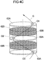
- the circular-cylindrical layer unit 6 extends along a cylinder axis and has in its interior a layer package of several layer layers 63A, 63B of different porosity.
- a top side 60 and a bottom side 61 in a middle part 62 of the layer unit 6 are sandwiched a plurality of circular disc-shaped layer layers 63A of a material impermeable to the storage gas and the test gas, for example rubber, and layer layers 63B of a porous, spongy material, for example an aluminum foam arranged.
- seven layer layers 63B of a porous, sponge-like material are provided in this case, which are separated in pairs from six layer layers 63A made of non-porous material.
- Two further layer layers 63A of the non-porous material are also provided on the upper side 60 and the lower side 61, so that they function as final layer layers and between them the seven porous layer layers 63B and the six non-porous layer layers 63A are arranged.
- the porous layer layers 63B have a thickness that is many times greater than the thickness of the relatively flat non-porous layer layers 63A.
- the porous layer layers 63B are formed identical to each other, as well as the non-porous layer layers 63A are formed identical to each other. In principle, however, it would also be conceivable, for example, to choose the thickness of the sponge-like, porous layer layers 63B different from one another.
- the porous layer layers 63B have a pore density of 10 to 30 ppi throughout.
- the layer unit 6 also has a minimum diameter of about 60 mm and a minimum length of about 1000 mm.
- each of the non-porous layer layers 63A has an opening O1, O2 or O3.
- Such an opening O1, O2, O3 is provided at a distance from the central cylinder axis and lies here in the region of a radial edge of the respective layer layer 63A.
- the individual layer layers 63A are each arranged rotated by 180 ° relative to the non-porous layer layer 63A following along the cylinder axis.
- An example in the FIG. 4C indicated gas flow G must thus cover as long as possible on a path through the layer unit 6 by a provided between two non-porous layer layers 63A porous layer layer 63B.
- the gas can thus not parallel to the cylinder axis by two successive openings O1, O2 or O2, O3 flow, but also flows transversely to the cylinder axis through a porous layer layer 63B between these openings O1, O2 or O2, O3.
- the gas has to travel a longer distance than with an open access bore 3, so that the convection and diffusion processes take place more slowly in terms of time when the convection barrier with the layer unit 6 is used.
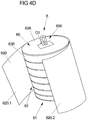
- the layer package comprising the layer layers 63A and 63B is surrounded radially in a protective manner by a flexible jacket 620.
- This jacket 620 is made of a flexible plastic material, for example, and on the one hand protects the layer layers 63A, 63B from damage and contamination when inserting the layer unit 6 into the access hole 3.
- the flexibility of the jacket 620 ensures that the layer unit 6 seals against a ( Pipe) inner wall of the access hole 3 is applied, so that gas can not flow past the layer unit between the inner wall and the jacket 620, but the gas must always flow over the layer layers 63A and 63B.
- the sheath 620 may be formed by, for example, a flexible plastic sheet which is once wound circumferentially around the layer package of the layer layers 63A and 63B. Free longitudinal ends 620.1 and 620.2 of the cladding 620 are then fixed together so that the cladding 620 protectively surrounds the cladding layers 63A and 63B. A connection of the two ends 620.1 and 620.2 of the sheath 620 is in the FIG. 4A illustrated by a linear and parallel to the cylinder axis running joint. In order to fix the sheathing 620 to the layer package, the sheath 620 is additionally connected to the upper side 60 and the underside 61 with the respective end layer layer 63A.
- the individual layer layers 63A and 63B are clamped between the top side 60 and the bottom side 61, for example via a central axis along the cylinder axis and through all layer layers 63A and 63B 63B guided through connecting rod and at the ends of the underside 61 and the top 60 provided holding plates.
- this connecting rod is in the embodiment of the FIGS. 4A to 4D a fastener 600, provided here in the form of a metal ring.
- a connection to a setting device is possible, by means of which the layer unit 6 can be introduced immediately below the Bohrfußes (pipe shoe) of the access hole 3.
Landscapes
- Physics & Mathematics (AREA)
- General Physics & Mathematics (AREA)
- Life Sciences & Earth Sciences (AREA)
- Engineering & Computer Science (AREA)
- Geology (AREA)
- Mining & Mineral Resources (AREA)
- Geophysics (AREA)
- Environmental & Geological Engineering (AREA)
- Fluid Mechanics (AREA)
- General Life Sciences & Earth Sciences (AREA)
- Geochemistry & Mineralogy (AREA)
- Examining Or Testing Airtightness (AREA)
Claims (15)
- Procédé servant à vérifier l'étanchéité d'un trou d'accès (3) d'une cavité (4), qui est déjà remplie d'un gaz de stockage, en soumettant la cavité (4) à l'action d'un gaz de test,
caractérisé par- la superposition du gaz de stockage se trouvant dans la cavité (4) et d'un gaz de test en une quantité prédéfinie si bien qu'une couche limite se forme entre le gaz de stockage et le gaz de test, dans lequel le gaz de test présente une densité inférieure à celle du gaz de stockage,- l'évacuation du gaz de test après une durée prédéfinie ;- l'établissement du bilan de la quantité du gaz de test. - Procédé selon la revendication 1,
caractérisé par
la détermination de l'arrivée de la couche limite se déplaçant lors de l'évacuation du gaz de test au niveau d'un emplacement de prélèvement et/ou lors de l'utilisation d'un dispositif servant à réduire l'écoulement par convection et par diffusion entre le gaz de stockage et le gaz de test. - Procédé selon la revendication 2,
caractérisé en ce que
le dispositif servant à réduire l'écoulement par convection et par diffusion est utilisé au niveau de l'emplacement sous un sabot de tubage, au niveau duquel la couche limite entre le gaz de test et le gaz de stockage est présente pendant une phase de repos avant l'évacuation du gaz de test. - Procédé selon la revendication 2 ou 3,
caractérisé en ce que
le dispositif servant à réduire l'écoulement par convection et par diffusion- présente une éponge métallique, qui est utilisée avant la superposition du gaz de stockage dans l'embase d'un trou d'accès de la cavité, et/ou- présente un soufflet pouvant être gonflé avec une éponge servant à éviter une chute de pression entre le gaz de stockage et le gaz de test par l'intermédiaire du soufflet, qui est utilisé avant la superposition du gaz de stockage dans l'embase d'un trou d'accès de la cavité. - Procédé selon l'une quelconque des revendications 2 à 4,
caractérisé en ce que- le dispositif comprend une unité de couche (6) destinée à être insérée dans un trou d'accès de la cavité (4), et l'unité de couche (6) présente au moins deux strates de couche (63A, 63B) à porosité différente se suivant les unes les autres le long d'un axe d'extension, et/ou- un dispositif de pose est employé pour introduire le dispositif servant à réduire l'écoulement par convection et par diffusion sous l'embase du trou d'accès (3) de la cavité (4). - Procédé selon l'une quelconque des revendications 1 à 5,
caractérisé par
la commande de la quantité de distribution et/ou d'évacuation du gaz de test par unité de temps en fonction du profil de volume connu de la cavité dans la zone d'un trou d'accès de la cavité. - Dispositif servant à réduire l'écoulement par convection et diffusion entre un gaz de stockage se trouvant dans une cavité et un gaz de test, qui est introduit en une quantité prédéfinie dans la cavité (4) aux fins de la vérification de l'étanchéité d'un trou d'accès (3) de la cavité (4) et auquel le gaz de stockage se trouvant dans la cavité (4) est superposé, dans lequel- le dispositif présente un soufflet pouvant être gonflé destiné à être inséré dans un trou d'accès de la cavité (4) et une membrane ou une éponge est prévue dans le soufflet,- le soufflet peut isoler une couche de gaz de stockage d'une couche de gaz de test lors de la vérification de l'étanchéité de la cavité (4) remplie du gaz de stockage et- la membrane ou l'éponge relie les deux couches de gaz entre elles.
- Dispositif servant à réduire l'écoulement par convection et diffusion entre un gaz de stockage se trouvant dans une cavité et un gaz de test, qui est introduit dans la cavité (4) en une quantité prédéfinie aux fins de la vérification de l'étanchéité d'un trou d'accès (3) de la cavité (4) et auquel le gaz de stockage se trouvant dans la cavité (4) est superposé, dans lequel- le dispositif comprend une unité de couche (6) destinée à être insérée dans un trou d'accès de la cavité (4) et l'unité de couche (6) présente au moins deux strates de couche (63A, 63B) à porosité différente se suivant les unes les autres le long de l'axe d'extension,- l'unité de couche (6) peut isoler lors de la vérification de l'étanchéité de la cavité (4) remplie du gaz de stockage une couche de gaz de stockage d'une couche de gaz de test, et- les deux couches de gaz peuvent être reliées l'une à l'autre par l'intermédiaire des strates de couche (63A, 6B).
- Dispositif selon la revendication 8, caractérisé en ce que- une strate de couche (63B) présente un matériau spongieux, et/ou- une strate de couche (63A) d'un premier type et une strate de couche (63B) d'un deuxième type alternent le long de l'axe d'extension, et/ou- des strates de couche (63A) du premier type composées d'un matériau en plastique et des strates de couche (63B) du deuxième type sont fabriquées à partir d'un métal.
- Dispositif selon la revendication 9, caractérisé en ce que la strate de couche (63A) du premier type est fabriquée à partir d'un matériau, qui de loin ne laisse pas passer le gaz, et la strate de couche (63A) du premier type présente au moins une ouverture (O1, O2, O3), à travers laquelle du gaz peut s'écouler.
- Dispositif selon la revendication 10, caractérisé en ce qu'une ouverture (O1, O2, O3) d'une première strate de couche (63A) du premier type est disposée de manière décalée par rapport à une ouverture (O3, O1, O2) d'une deuxième strate de couche (63A) du premier type.
- Dispositif selon la revendication 11, caractérisé en ce que les deux strates de couche (63A) du premier type par rapport à l'axe d'extension sont disposées en étant tournées l'une par rapport à l'autre d'un angle supérieur à 45°, en particulier d'un angle de 180°.
- Dispositif selon l'une quelconque des revendications 8 à 12, caractérisé en ce que l'unité de couche (6) présente une gaine (620) qui entoure les strates de couche (63A, 63B) et est réalisée et prévue pour reposer de manière étanche contre une paroi intérieure de trou d'accès lors de l'insertion de l'unité de couche (6) dans le trou d'alésage.
- Utilisation d'un soufflet pouvant être gonflé avec une membrane prévue à l'intérieur ou une éponge prévue à l'intérieur pour réduire l'écoulement par convection et diffusion entre un gaz de stockage se trouvant dans une cavité souterraine et un gaz de test lors de la vérification de l'étanchéité de la cavité remplie du gaz de stockage à l'aide du gaz de test.
- Utilisation d'une unité de couche (6) avec au moins deux strates de couche (63A, 63B) à porosité différente pour réduire l'écoulement par convection et diffusion entre un gaz de stockage se trouvant dans une cavité souterraine et un gaz de test lors de la vérification de l'étanchéité de la cavité remplie de gaz de stockage à l'aide du gaz de test.
Applications Claiming Priority (3)
| Application Number | Priority Date | Filing Date | Title |
|---|---|---|---|
| US201261607082P | 2012-03-06 | 2012-03-06 | |
| PCT/DE2012/000217 WO2013131500A1 (fr) | 2012-03-06 | 2012-03-06 | Procédé de vérification de l'étanchéité de trous d'accès de cavernes |
| PCT/EP2013/054401 WO2013131914A2 (fr) | 2012-03-06 | 2013-03-05 | Procédé de contrôle de l'étanchéité de cavités et dispositif de réduction de l'écoulement par convection et par diffusion |
Publications (3)
| Publication Number | Publication Date |
|---|---|
| EP2823146A2 EP2823146A2 (fr) | 2015-01-14 |
| EP2823146B1 true EP2823146B1 (fr) | 2018-08-15 |
| EP2823146B8 EP2823146B8 (fr) | 2018-10-31 |
Family
ID=47997371
Family Applications (1)
| Application Number | Title | Priority Date | Filing Date |
|---|---|---|---|
| EP13712161.2A Active EP2823146B8 (fr) | 2012-03-06 | 2013-03-05 | Procédé de contrôle de l'étanchéité du puits d'acces d'une cavité souterraine et dispositif de réduction de l'écoulement par convection et par diffusion |
Country Status (3)
| Country | Link |
|---|---|
| US (1) | US9869175B2 (fr) |
| EP (1) | EP2823146B8 (fr) |
| WO (1) | WO2013131914A2 (fr) |
Families Citing this family (2)
| Publication number | Priority date | Publication date | Assignee | Title |
|---|---|---|---|---|
| EP2993456A1 (fr) * | 2014-09-08 | 2016-03-09 | Inficon GmbH | Procédé de recherche précise sélective de fuites de gaz de distribution publique pendant le fonctionnement |
| CN119688203B (zh) * | 2025-02-26 | 2025-05-23 | 淄博明派电气股份有限公司 | 一种变电柜的舱体密封性测试装置 |
Family Cites Families (1)
| Publication number | Priority date | Publication date | Assignee | Title |
|---|---|---|---|---|
| DE4226613C1 (de) * | 1992-08-07 | 1994-02-24 | Untergrundspeicher Und Geotech | Verfahren und Einrichtung zur Dichtheitsprüfung an rohrschuhnahnen Zementationsintervallen |
-
2013
- 2013-03-05 WO PCT/EP2013/054401 patent/WO2013131914A2/fr not_active Ceased
- 2013-03-05 EP EP13712161.2A patent/EP2823146B8/fr active Active
- 2013-03-05 US US14/383,089 patent/US9869175B2/en not_active Expired - Fee Related
Non-Patent Citations (1)
| Title |
|---|
| None * |
Also Published As
| Publication number | Publication date |
|---|---|
| EP2823146A2 (fr) | 2015-01-14 |
| US20150007649A1 (en) | 2015-01-08 |
| EP2823146B8 (fr) | 2018-10-31 |
| US9869175B2 (en) | 2018-01-16 |
| WO2013131914A2 (fr) | 2013-09-12 |
| WO2013131914A3 (fr) | 2014-07-17 |
Similar Documents
| Publication | Publication Date | Title |
|---|---|---|
| CN110320149B (zh) | 一种流向可调式不规则岩样高压渗透装置及测试方法 | |
| DE68927569T2 (de) | Vorrichtung im Bohrloch und Verfahren zur Bestimmung der Eigenschaften einer Formation | |
| DE4429136C2 (de) | Multi-Level-Packersystem zur Probennahme, insbesondere Grundwasser-Probennahme, und/oder Meßwertaufnahme von physikalischen, chemischen und/oder geophysikalischen Parametern in unterschiedlichen Tiefen in einem Bohrloch | |
| US20100089124A1 (en) | Integrated porous rigid wall and flexible wall permeability test device for soils | |
| EP2823146B1 (fr) | Procédé de contrôle de l'étanchéité du puits d'acces d'une cavité souterraine et dispositif de réduction de l'écoulement par convection et par diffusion | |
| DE102014000342B4 (de) | Verfahren und Vorrichtung zur selektiven Dichtheitsprüfung von Kanalrohren | |
| Seah et al. | Horizontal coefficient of consolidation of soft Bangkok clay | |
| US11092588B2 (en) | Measurement cell and associated measurement method | |
| EP1273902A2 (fr) | Dispositif et procédé pour mesurer la perméabilité au gaz d'un matériau de construction | |
| DE4310096A1 (de) | Verfahren und Einrichtung zur Messung des Radongehaltes im Bodengas | |
| DE102011105486A1 (de) | Verfahren zur Langzeitmessung der Exhalationsrates einer gasförmigen Substanz und Vorrichtung zur Durchführung | |
| DE69004960T2 (de) | Verfahren und gerät zur messung vor ort der quellcharakteristik von böden. | |
| DE102007010856B4 (de) | Verfahren und Einrichtung zum Nachweis der Dichtheit | |
| DE69000789T2 (de) | Vorrichtung zur gewinnung einer fluessigkeit aus einem langen rohr. | |
| WO2013131500A1 (fr) | Procédé de vérification de l'étanchéité de trous d'accès de cavernes | |
| DE1533620A1 (de) | Verfahren zur Untersuchung von Bohrloechern | |
| DE3922209C2 (fr) | ||
| DE69314113T2 (de) | Verfahren zum Prüfen der Dichtigkeit einer Kanalisation oder eines Kanalisationsnetzes sowie eine Anlage zur Durchführung des Verfahrens | |
| DE3526325C2 (fr) | ||
| Moore et al. | A new methodology to evaluate huff and puff effectiveness at in-situ conditions | |
| DE2062688B2 (de) | Verfahren und vorrichtung zum messen der veraenderungen des um einen bergmaennischen hohlraum anstehenden gebirges mit hilfe von messankern | |
| CH331148A (de) | Verfahren und Vorrichtung zur Probeentnahme und zum Messen bodenphysikalischer Kennwerte des Untergrundes | |
| DE102023109668A1 (de) | Verfahren und vorrichtung zur messung von gasdiffusionskoeffizienten durch poröse materialien unter erhöhtem gasdruck | |
| Dong | On the role of constitutive behaviour in the response of squeezing ground to tunnelling | |
| Ghosh | Permeability of Indian coal |
Legal Events
| Date | Code | Title | Description |
|---|---|---|---|
| PUAI | Public reference made under article 153(3) epc to a published international application that has entered the european phase |
Free format text: ORIGINAL CODE: 0009012 |
|
| 17P | Request for examination filed |
Effective date: 20140919 |
|
| AK | Designated contracting states |
Kind code of ref document: A2 Designated state(s): AL AT BE BG CH CY CZ DE DK EE ES FI FR GB GR HR HU IE IS IT LI LT LU LV MC MK MT NL NO PL PT RO RS SE SI SK SM TR |
|
| AX | Request for extension of the european patent |
Extension state: BA ME |
|
| DAX | Request for extension of the european patent (deleted) | ||
| GRAP | Despatch of communication of intention to grant a patent |
Free format text: ORIGINAL CODE: EPIDOSNIGR1 |
|
| STAA | Information on the status of an ep patent application or granted ep patent |
Free format text: STATUS: GRANT OF PATENT IS INTENDED |
|
| INTG | Intention to grant announced |
Effective date: 20180327 |
|
| GRAS | Grant fee paid |
Free format text: ORIGINAL CODE: EPIDOSNIGR3 |
|
| GRAA | (expected) grant |
Free format text: ORIGINAL CODE: 0009210 |
|
| STAA | Information on the status of an ep patent application or granted ep patent |
Free format text: STATUS: THE PATENT HAS BEEN GRANTED |
|
| AK | Designated contracting states |
Kind code of ref document: B1 Designated state(s): AL AT BE BG CH CY CZ DE DK EE ES FI FR GB GR HR HU IE IS IT LI LT LU LV MC MK MT NL NO PL PT RO RS SE SI SK SM TR |
|
| REG | Reference to a national code |
Ref country code: CH Ref legal event code: EP Ref country code: GB Ref legal event code: FG4D Free format text: NOT ENGLISH Ref country code: AT Ref legal event code: REF Ref document number: 1029995 Country of ref document: AT Kind code of ref document: T Effective date: 20180815 |
|
| REG | Reference to a national code |
Ref country code: IE Ref legal event code: FG4D Free format text: LANGUAGE OF EP DOCUMENT: GERMAN |
|
| REG | Reference to a national code |
Ref country code: DE Ref legal event code: R096 Ref document number: 502013010860 Country of ref document: DE |
|
| REG | Reference to a national code |
Ref country code: CH Ref legal event code: PK Free format text: BERICHTIGUNGEN |
|
| RIN2 | Information on inventor provided after grant (corrected) |
Inventor name: ABDEL HAQ, AMER |
|
| REG | Reference to a national code |
Ref country code: CH Ref legal event code: PK Free format text: BERICHTIGUNG B8 |
|
| REG | Reference to a national code |
Ref country code: NL Ref legal event code: FP |
|
| REG | Reference to a national code |
Ref country code: LT Ref legal event code: MG4D |
|
| PG25 | Lapsed in a contracting state [announced via postgrant information from national office to epo] |
Ref country code: GR Free format text: LAPSE BECAUSE OF FAILURE TO SUBMIT A TRANSLATION OF THE DESCRIPTION OR TO PAY THE FEE WITHIN THE PRESCRIBED TIME-LIMIT Effective date: 20181116 Ref country code: NO Free format text: LAPSE BECAUSE OF FAILURE TO SUBMIT A TRANSLATION OF THE DESCRIPTION OR TO PAY THE FEE WITHIN THE PRESCRIBED TIME-LIMIT Effective date: 20181115 Ref country code: IS Free format text: LAPSE BECAUSE OF FAILURE TO SUBMIT A TRANSLATION OF THE DESCRIPTION OR TO PAY THE FEE WITHIN THE PRESCRIBED TIME-LIMIT Effective date: 20181215 Ref country code: LT Free format text: LAPSE BECAUSE OF FAILURE TO SUBMIT A TRANSLATION OF THE DESCRIPTION OR TO PAY THE FEE WITHIN THE PRESCRIBED TIME-LIMIT Effective date: 20180815 Ref country code: BG Free format text: LAPSE BECAUSE OF FAILURE TO SUBMIT A TRANSLATION OF THE DESCRIPTION OR TO PAY THE FEE WITHIN THE PRESCRIBED TIME-LIMIT Effective date: 20181115 Ref country code: FI Free format text: LAPSE BECAUSE OF FAILURE TO SUBMIT A TRANSLATION OF THE DESCRIPTION OR TO PAY THE FEE WITHIN THE PRESCRIBED TIME-LIMIT Effective date: 20180815 Ref country code: RS Free format text: LAPSE BECAUSE OF FAILURE TO SUBMIT A TRANSLATION OF THE DESCRIPTION OR TO PAY THE FEE WITHIN THE PRESCRIBED TIME-LIMIT Effective date: 20180815 Ref country code: SE Free format text: LAPSE BECAUSE OF FAILURE TO SUBMIT A TRANSLATION OF THE DESCRIPTION OR TO PAY THE FEE WITHIN THE PRESCRIBED TIME-LIMIT Effective date: 20180815 |
|
| PG25 | Lapsed in a contracting state [announced via postgrant information from national office to epo] |
Ref country code: AL Free format text: LAPSE BECAUSE OF FAILURE TO SUBMIT A TRANSLATION OF THE DESCRIPTION OR TO PAY THE FEE WITHIN THE PRESCRIBED TIME-LIMIT Effective date: 20180815 Ref country code: LV Free format text: LAPSE BECAUSE OF FAILURE TO SUBMIT A TRANSLATION OF THE DESCRIPTION OR TO PAY THE FEE WITHIN THE PRESCRIBED TIME-LIMIT Effective date: 20180815 Ref country code: HR Free format text: LAPSE BECAUSE OF FAILURE TO SUBMIT A TRANSLATION OF THE DESCRIPTION OR TO PAY THE FEE WITHIN THE PRESCRIBED TIME-LIMIT Effective date: 20180815 |
|
| PG25 | Lapsed in a contracting state [announced via postgrant information from national office to epo] |
Ref country code: PL Free format text: LAPSE BECAUSE OF FAILURE TO SUBMIT A TRANSLATION OF THE DESCRIPTION OR TO PAY THE FEE WITHIN THE PRESCRIBED TIME-LIMIT Effective date: 20180815 Ref country code: EE Free format text: LAPSE BECAUSE OF FAILURE TO SUBMIT A TRANSLATION OF THE DESCRIPTION OR TO PAY THE FEE WITHIN THE PRESCRIBED TIME-LIMIT Effective date: 20180815 Ref country code: IT Free format text: LAPSE BECAUSE OF FAILURE TO SUBMIT A TRANSLATION OF THE DESCRIPTION OR TO PAY THE FEE WITHIN THE PRESCRIBED TIME-LIMIT Effective date: 20180815 Ref country code: RO Free format text: LAPSE BECAUSE OF FAILURE TO SUBMIT A TRANSLATION OF THE DESCRIPTION OR TO PAY THE FEE WITHIN THE PRESCRIBED TIME-LIMIT Effective date: 20180815 Ref country code: ES Free format text: LAPSE BECAUSE OF FAILURE TO SUBMIT A TRANSLATION OF THE DESCRIPTION OR TO PAY THE FEE WITHIN THE PRESCRIBED TIME-LIMIT Effective date: 20180815 Ref country code: CZ Free format text: LAPSE BECAUSE OF FAILURE TO SUBMIT A TRANSLATION OF THE DESCRIPTION OR TO PAY THE FEE WITHIN THE PRESCRIBED TIME-LIMIT Effective date: 20180815 |
|
| REG | Reference to a national code |
Ref country code: DE Ref legal event code: R097 Ref document number: 502013010860 Country of ref document: DE |
|
| PG25 | Lapsed in a contracting state [announced via postgrant information from national office to epo] |
Ref country code: SK Free format text: LAPSE BECAUSE OF FAILURE TO SUBMIT A TRANSLATION OF THE DESCRIPTION OR TO PAY THE FEE WITHIN THE PRESCRIBED TIME-LIMIT Effective date: 20180815 Ref country code: DK Free format text: LAPSE BECAUSE OF FAILURE TO SUBMIT A TRANSLATION OF THE DESCRIPTION OR TO PAY THE FEE WITHIN THE PRESCRIBED TIME-LIMIT Effective date: 20180815 Ref country code: SM Free format text: LAPSE BECAUSE OF FAILURE TO SUBMIT A TRANSLATION OF THE DESCRIPTION OR TO PAY THE FEE WITHIN THE PRESCRIBED TIME-LIMIT Effective date: 20180815 |
|
| PLBE | No opposition filed within time limit |
Free format text: ORIGINAL CODE: 0009261 |
|
| STAA | Information on the status of an ep patent application or granted ep patent |
Free format text: STATUS: NO OPPOSITION FILED WITHIN TIME LIMIT |
|
| 26N | No opposition filed |
Effective date: 20190516 |
|
| PG25 | Lapsed in a contracting state [announced via postgrant information from national office to epo] |
Ref country code: SI Free format text: LAPSE BECAUSE OF FAILURE TO SUBMIT A TRANSLATION OF THE DESCRIPTION OR TO PAY THE FEE WITHIN THE PRESCRIBED TIME-LIMIT Effective date: 20180815 |
|
| PG25 | Lapsed in a contracting state [announced via postgrant information from national office to epo] |
Ref country code: MC Free format text: LAPSE BECAUSE OF FAILURE TO SUBMIT A TRANSLATION OF THE DESCRIPTION OR TO PAY THE FEE WITHIN THE PRESCRIBED TIME-LIMIT Effective date: 20180815 |
|
| REG | Reference to a national code |
Ref country code: CH Ref legal event code: PL |
|
| PG25 | Lapsed in a contracting state [announced via postgrant information from national office to epo] |
Ref country code: LU Free format text: LAPSE BECAUSE OF NON-PAYMENT OF DUE FEES Effective date: 20190305 |
|
| REG | Reference to a national code |
Ref country code: BE Ref legal event code: MM Effective date: 20190331 |
|
| PG25 | Lapsed in a contracting state [announced via postgrant information from national office to epo] |
Ref country code: LI Free format text: LAPSE BECAUSE OF NON-PAYMENT OF DUE FEES Effective date: 20190331 Ref country code: IE Free format text: LAPSE BECAUSE OF NON-PAYMENT OF DUE FEES Effective date: 20190305 Ref country code: CH Free format text: LAPSE BECAUSE OF NON-PAYMENT OF DUE FEES Effective date: 20190331 |
|
| PG25 | Lapsed in a contracting state [announced via postgrant information from national office to epo] |
Ref country code: BE Free format text: LAPSE BECAUSE OF NON-PAYMENT OF DUE FEES Effective date: 20190331 |
|
| PG25 | Lapsed in a contracting state [announced via postgrant information from national office to epo] |
Ref country code: TR Free format text: LAPSE BECAUSE OF FAILURE TO SUBMIT A TRANSLATION OF THE DESCRIPTION OR TO PAY THE FEE WITHIN THE PRESCRIBED TIME-LIMIT Effective date: 20180815 |
|
| PG25 | Lapsed in a contracting state [announced via postgrant information from national office to epo] |
Ref country code: MT Free format text: LAPSE BECAUSE OF FAILURE TO SUBMIT A TRANSLATION OF THE DESCRIPTION OR TO PAY THE FEE WITHIN THE PRESCRIBED TIME-LIMIT Effective date: 20180815 Ref country code: PT Free format text: LAPSE BECAUSE OF FAILURE TO SUBMIT A TRANSLATION OF THE DESCRIPTION OR TO PAY THE FEE WITHIN THE PRESCRIBED TIME-LIMIT Effective date: 20181215 |
|
| REG | Reference to a national code |
Ref country code: AT Ref legal event code: MM01 Ref document number: 1029995 Country of ref document: AT Kind code of ref document: T Effective date: 20190305 |
|
| PG25 | Lapsed in a contracting state [announced via postgrant information from national office to epo] |
Ref country code: AT Free format text: LAPSE BECAUSE OF NON-PAYMENT OF DUE FEES Effective date: 20190305 |
|
| PG25 | Lapsed in a contracting state [announced via postgrant information from national office to epo] |
Ref country code: CY Free format text: LAPSE BECAUSE OF FAILURE TO SUBMIT A TRANSLATION OF THE DESCRIPTION OR TO PAY THE FEE WITHIN THE PRESCRIBED TIME-LIMIT Effective date: 20180815 |
|
| PG25 | Lapsed in a contracting state [announced via postgrant information from national office to epo] |
Ref country code: HU Free format text: LAPSE BECAUSE OF FAILURE TO SUBMIT A TRANSLATION OF THE DESCRIPTION OR TO PAY THE FEE WITHIN THE PRESCRIBED TIME-LIMIT; INVALID AB INITIO Effective date: 20130305 |
|
| PG25 | Lapsed in a contracting state [announced via postgrant information from national office to epo] |
Ref country code: MK Free format text: LAPSE BECAUSE OF FAILURE TO SUBMIT A TRANSLATION OF THE DESCRIPTION OR TO PAY THE FEE WITHIN THE PRESCRIBED TIME-LIMIT Effective date: 20180815 |
|
| PGFP | Annual fee paid to national office [announced via postgrant information from national office to epo] |
Ref country code: GB Payment date: 20260324 Year of fee payment: 14 |
|
| PGFP | Annual fee paid to national office [announced via postgrant information from national office to epo] |
Ref country code: DE Payment date: 20260330 Year of fee payment: 14 |
|
| PGFP | Annual fee paid to national office [announced via postgrant information from national office to epo] |
Ref country code: NL Payment date: 20260323 Year of fee payment: 14 |
|
| PGFP | Annual fee paid to national office [announced via postgrant information from national office to epo] |
Ref country code: FR Payment date: 20260324 Year of fee payment: 14 |