EP2823200B2 - Gamme de boîtiers d'engrenage - Google Patents
Gamme de boîtiers d'engrenage Download PDFInfo
- Publication number
- EP2823200B2 EP2823200B2 EP13717468.6A EP13717468A EP2823200B2 EP 2823200 B2 EP2823200 B2 EP 2823200B2 EP 13717468 A EP13717468 A EP 13717468A EP 2823200 B2 EP2823200 B2 EP 2823200B2
- Authority
- EP
- European Patent Office
- Prior art keywords
- drive flange
- gear
- gear train
- flange
- series according
- Prior art date
- Legal status (The legal status is an assumption and is not a legal conclusion. Google has not performed a legal analysis and makes no representation as to the accuracy of the status listed.)
- Active
Links
Images


Classifications
-
- F—MECHANICAL ENGINEERING; LIGHTING; HEATING; WEAPONS; BLASTING
- F16—ENGINEERING ELEMENTS AND UNITS; GENERAL MEASURES FOR PRODUCING AND MAINTAINING EFFECTIVE FUNCTIONING OF MACHINES OR INSTALLATIONS; THERMAL INSULATION IN GENERAL
- F16H—GEARING
- F16H57/00—General details of gearing
- F16H57/02—Gearboxes; Mounting gearing therein
- F16H57/033—Series gearboxes, e.g. gearboxes based on the same design being available in different sizes or gearboxes using a combination of several standardised units
-
- F—MECHANICAL ENGINEERING; LIGHTING; HEATING; WEAPONS; BLASTING
- F16—ENGINEERING ELEMENTS AND UNITS; GENERAL MEASURES FOR PRODUCING AND MAINTAINING EFFECTIVE FUNCTIONING OF MACHINES OR INSTALLATIONS; THERMAL INSULATION IN GENERAL
- F16H—GEARING
- F16H57/00—General details of gearing
- F16H57/02—Gearboxes; Mounting gearing therein
- F16H2057/02013—Extension units for gearboxes, e.g. additional units attached to a main gear
-
- F—MECHANICAL ENGINEERING; LIGHTING; HEATING; WEAPONS; BLASTING
- F16—ENGINEERING ELEMENTS AND UNITS; GENERAL MEASURES FOR PRODUCING AND MAINTAINING EFFECTIVE FUNCTIONING OF MACHINES OR INSTALLATIONS; THERMAL INSULATION IN GENERAL
- F16H—GEARING
- F16H57/00—General details of gearing
- F16H57/02—Gearboxes; Mounting gearing therein
- F16H2057/02034—Gearboxes combined or connected with electric machines
-
- F—MECHANICAL ENGINEERING; LIGHTING; HEATING; WEAPONS; BLASTING
- F16—ENGINEERING ELEMENTS AND UNITS; GENERAL MEASURES FOR PRODUCING AND MAINTAINING EFFECTIVE FUNCTIONING OF MACHINES OR INSTALLATIONS; THERMAL INSULATION IN GENERAL
- F16H—GEARING
- F16H57/00—General details of gearing
- F16H57/02—Gearboxes; Mounting gearing therein
- F16H2057/02039—Gearboxes for particular applications
- F16H2057/02069—Gearboxes for particular applications for industrial applications
-
- F—MECHANICAL ENGINEERING; LIGHTING; HEATING; WEAPONS; BLASTING
- F16—ENGINEERING ELEMENTS AND UNITS; GENERAL MEASURES FOR PRODUCING AND MAINTAINING EFFECTIVE FUNCTIONING OF MACHINES OR INSTALLATIONS; THERMAL INSULATION IN GENERAL
- F16H—GEARING
- F16H57/00—General details of gearing
- F16H57/02—Gearboxes; Mounting gearing therein
- F16H2057/02039—Gearboxes for particular applications
- F16H2057/02069—Gearboxes for particular applications for industrial applications
- F16H2057/02073—Reduction gearboxes for industry
-
- Y—GENERAL TAGGING OF NEW TECHNOLOGICAL DEVELOPMENTS; GENERAL TAGGING OF CROSS-SECTIONAL TECHNOLOGIES SPANNING OVER SEVERAL SECTIONS OF THE IPC; TECHNICAL SUBJECTS COVERED BY FORMER USPC CROSS-REFERENCE ART COLLECTIONS [XRACs] AND DIGESTS
- Y10—TECHNICAL SUBJECTS COVERED BY FORMER USPC
- Y10T—TECHNICAL SUBJECTS COVERED BY FORMER US CLASSIFICATION
- Y10T74/00—Machine element or mechanism
- Y10T74/21—Elements
- Y10T74/2186—Gear casings
Definitions
- the present invention relates to a series of gearbox housings.
- a housing for a transmission that has a plurality of openings.
- the housing is designed to accommodate an input shaft and an output shaft in different relative orientations to one another.
- the input shaft and the output shaft can be provided with gears, bevel gears, and/or worm gears, thus creating a spur gear, a bevel gear, or a worm gear.
- the input and output shafts are each rotatably received in shaft bearings that are connected to the housing.
- bores for attaching a motor are provided on the outside of the housing.
- the genre-forming printed matter DE 1 203 075 B discloses a gearbox housing usable for multiple gearbox types, which, when assembled, is closed on two opposite sides by an end cover.
- a first end cover has a plurality of bearing openings spaced at different distances from one another. This allows for different center distances in the gearbox.
- the second end cover is designed to correspond to the first end cover.
- the end covers are designed to be rotatable relative to the housing. As a result, the shafts and gears in the housing can be positioned differently depending on the desired installation position of the gearbox within the housing.
- the document DE 41 21 299 A1 discloses a gear housing having a mounting opening on one side.
- the housing is designed to accommodate two shafts, on which a worm gear and a worm are mounted, which interact as a worm gear.
- the housing has bearing points designed to accommodate shaft bearings in which the shaft with the worm is rotatably mounted.
- the shaft with the worm is driven via a spur gear stage by a drive shaft that extends through a connecting flange.
- circular bearing openings surrounded by bores are formed on the outside of the housing.
- the object of the present invention is to provide a series of gearbox housings which have an improved interface for attaching a motor, an adapter plate or another gearbox.
- the series of gear housings comprises various sizes. Each size comprises a series of different housing types.
- the housing types are suitable for a spur gear unit and at least one of the following types: bevel gear units, parallel shaft gear units, and worm gear units.
- Each gear housing has a housing opening on the drive side. The housing opening is surrounded by a drive flange for connecting a motor, an adapter plate, or another gear unit.
- the axes of bearing points running perpendicular to the plane of the drive flange which are intended to accommodate shaft bearings for geared parts, lie within a minimum inner diameter of the drive flange when viewed perpendicular to the plane of the drive flange.
- Different sizes differ in their housing dimensions, which are determined in particular by the center distances of the first gear stage, and thus by the power rating.
- the drive flange is a drive-side connection flange designed as a flat surface to which a connection flange of a motor, another gearbox, or an adapter plate is attached.
- a sealant such as a sealing ring, is typically arranged between the two superimposed flanges.
- a plane located within this surface is referred to as the drive flange plane.
- Bearing locations are also called bearing seats.
- Each bearing seat can be assigned an axis that corresponds to the axis of a shaft bearing to be inserted into the bearing seat or of a shaft mounted in the shaft bearing.
- the term "geared parts” refers to all components that mesh or intermeshing with one another and are mounted in a rotating manner, such as spur gears, bevel gears, pinions, and worm gears.
- the invention is based on the finding that a significant benefit and advantage with regard to storage, assembly and maintenance of gear housings and gears based thereon, in particular industrial gears, is achieved if an interior of the gear housing accommodating toothed parts is optimally accessible via the drive interface.
- By maximizing the size of the housing opening it is achieved that the axes of bearing points running perpendicular to the plane of the drive flange, which are intended to accommodate shaft bearings for toothed parts, lie within a minimum inner diameter of the drive flange when viewed perpendicular to the plane of the drive flange. These axes are therefore easily accessible, which serves to facilitate simple and efficient assembly and maintenance, e.g. the adjustability of the bearings.
- the particular advantage is that the axial bearing position of the shafts, which run perpendicular to the plane of the drive flange, within the housing opening allows the bearings for these shafts to be mounted from the motor side, leaving sufficient space for a cover seal.
- the bearing for the bevel pinion shaft can thus also be mounted from the motor side, and the bore for the bevel pinion shaft bearing can be machined from the motor side.
- IEC International Electrotechnical Commission
- NEMA National Electrical Manufacturers Association
- the invention creates a universal motor-gearbox interface at a motor-side housing opening of a gearbox housing.
- the axes of bearing points running perpendicular to the plane of the drive flange, which are provided for receiving shaft bearings for gearing parts lie within the minimum inner diameter of the drive flange when viewed perpendicular to the plane of the drive flange.
- the advantage here is that the assembly and maintenance of shaft bearings, shafts and gearing parts is considerably simplified by the easily accessible location within the housing opening.
- the ratio of a maximum outer diameter of the drive flange to an axial distance of bearing points provided for receiving shaft bearings for gearing parts of a first gear stage is in a range of 2.74 to 3.00 in all sizes.
- the advantage here is that in this value range, the assembly and maintenance of shaft bearings, shafts and gearing parts of a first gear stage is considerably simplified by the easily accessible location within the housing opening.
- the ratio of the minimum outer diameter of the drive flange to the minimum inner diameter of the drive flange is in a range of 1.07 to 1.21 in all sizes.
- the advantage here is that, within this range of values, the opening width of the accessible housing opening is optimized with regard to the given dimensions of the housing, so that the assembly and maintenance of shaft bearings, shafts, and gearing components is significantly simplified due to the easily accessible location within the housing opening.
- holes are arranged in the drive flange, which lie on a bolt circle with a diameter and are intended to receive connecting screws, and wherein, in a design suitable for a spur gear, the ratio of a minimum outer diameter of the drive flange to the bolt circle diameter lies in a range of 0.97 to 1.05 in all sizes.
- the connection circuit with its sealing function is designed to be as space-saving as possible with regard to the given dimensions of the housing, so that the opening width of the accessible housing opening is maximized. In this way, the assembly and maintenance of shaft bearings, shafts and gearing parts is considerably simplified due to the easily accessible location within the housing opening.
- the drive flange is at least substantially circular, i.e., the inner and outer edges of the drive flange each extend at least substantially along an inner and outer circular line, respectively.
- the at least substantially circular flange surface is formed between the inner and outer circular lines.
- the restriction "at least substantially” encompasses the following configurations: the outer edge of the drive flange can have a non-curved section, a so-called flattening, in the 12 o'clock position and/or the 3 o'clock position and/or the 6 o'clock position and/or the 9 o'clock position. It is also possible for the outer edge of the drive flange to have a section with a curvature that differs from the circular part of the outer edge in the 6 o'clock position. Furthermore, the inner edge of the drive flange can have a section with a curvature that differs from the circular part of the inner edge in the 6 o'clock position.
- the drive flange has flattened portions on two opposite sides, the distance between which defines the minimum outer diameter of the drive flange.
- the flattened portions reduce the outer diameter of the connecting flange at the narrowest point of the housing, so that the end flange does not protrude beyond the housing.
- the drive flange has holes arranged point-symmetrically on a bolt circle with a bolt circle diameter and provided for receiving connecting screws.
- the connecting screws connect the drive flange to a corresponding connecting flange of a motor or gearbox.
- the hole circle runs over its entire The circumference of the flange is uninterrupted. This creates a continuous connection surface. This allows the pressure force generated by the connecting bolts to act on a sealing agent, such as a sealing ring, without interruption, thus achieving a reliable seal on the drive flange.
- the substantially circular drive flange has flats on two opposite sides. Eight holes are arranged in the drive flange, with four holes located in each half of the drive flange divided by a straight line separating the flats.
- a "straight line separating the flats" is understood to be a straight line running in the plane of the drive flange that coincides with the shortest connecting line between the opposing flats, i.e., the line connecting the two closest points of the opposing flats.
- the symmetrical hole pattern ensures reliable sealing of the drive flange.
- the holes are arranged outside of and symmetrically to the distance line and a perpendicular transverse line.
- the flange width is reduced at the flattened portions of the drive flange. Drilling a hole at such a narrow point would further reduce the width of a sealant, making reliable sealing impossible. Because the holes are located outside the distance line and the transverse line, i.e., outside the main axes of the drive flange, a sufficient width of a sealant can be ensured at these narrow points.
- the four holes arranged in a flange half are positioned such that a first hole is arranged at a first angle to the distance line, a second hole is arranged at a second angle to the first hole, and a third hole is arranged at a third angle to the second hole, wherein the angles are each measured from a center point of the hole circle, and wherein a ratio of the first to the third angle is constant, preferably 1/2, and a sum of the three angles lies in a range from 112.5 to 118.5.
- This angular position of the holes creates a drive flange with a hole pattern that is uniform for all gearbox housings, thereby increasing interchangeability and simplifying storage.
- a spur gear is designed with a gear housing from a series according to one of claims 1 to 9.
- the series of gear housings according to the invention is particularly well suited for modular gear motors.
- Fig. 1 shows a view of a gearbox housing Gij, which belongs to a series of gearbox housings that includes different sizes of gearbox housings.
- Fig. 2 shows a section of a bevel gear with the Fig. 1 shown gear housing Gij, the section plane being perpendicular to the plane 14 of the drive flange 11.
- the gearbox housing Gij is suitable for the bevel gear type.
- the gearbox housing Gij has a housing opening 10 on the drive side, which is closed by an adapter plate for the attachment of a motor.
- the axes 20 of the bearing points 21, which run perpendicular to the plane 14 of the drive flange 11 and are intended to accommodate shaft bearings, here: the bevel pinion shaft bearings 30, for gearing parts, here: the bevel pinion 31a and the gear 31b of the drive stage meshing with a drive pinion 32, are located in the Fig. 1 shown viewing direction, ie seen perpendicular to the plane 14 of the drive flange 11, within a minimum inner diameter b1 of the drive flange 11.
- the essentially circular drive flange 11 has flattened portions 12 of the outer edge 13a on two opposite sides. Eight holes L are arranged in the drive flange 11, which lie on a bolt circle LK and are provided for receiving connecting screws. Four holes L are arranged in each half 11a and 11b of the drive flange 11, which is divided by a straight line 40 between the flattened portions 12.
- Fig. 3 shows the same view as in Fig. 1 , in which a number of dimensions are additionally specified which are of importance for the invention.
- the figure shows the center distance a1 of the first gear stage.
- Fig. 2 In the bevel gear shown, this center distance a1 corresponds to the distance between the axis 34 of the drive pinion 32 and the axis 20 of the gear 31b meshing therewith.
- the figure also shows the distance q1 between the horizontally opposite flats, i.e., the length of the line connecting the two closest points of the opposite flats 12 on the outer edge 13a of the drive flange 11.
- the distance q1 corresponds to the minimum outer diameter of the drive flange 11, measured along the distance line 40.
- the figure also shows the minimum inner diameter b1 of the drive flange 11. Since the drive flange 11 has a recess 15 on its inner edge 13i in the area of the axis 20, the smallest inner diameter b1 must be measured outside the recess 15, e.g., along the distance line 40.
- the figure shows the bolt circle diameter e1, i.e. the diameter of the circle LK on which the holes L are arranged.
- the figure also shows the maximum outer diameter a2 of the drive flange 11. Since the drive flange 11 has flattened portions 12 on its outer edge 13a in the area of the connecting straight line 40 and the transverse straight line 41 rotated by 90 degrees thereto, the maximum outer diameter a2 must be measured outside the flattened portions 12, e.g. in the diagonal between the distance straight line 40 and the transverse straight line 41.
- Fig. 4 provides a table of the dimensions a1, q1, b1, e1 and a2 (see columns 2 to 6), as well as certain ratios QA, QB and QC of these dimensions (see columns 7 to 9).
- the ratio QA is the ratio of the distance q1 of the horizontally opposite flats q1 to the bolt circle diameter e1.
- the ratio QB is the ratio of the distance q1 of the horizontally opposite flats q1 to the minimum inside diameter b1 of the drive flange 11.
- the ratio QC is the ratio of the maximum outside diameter a2 of the drive flange 11 to the center distance a1 of the first gear stage.
- the specified values are within ranges selected so that the shaft bearings, shafts, and gearing components of the gearboxes are easily accessible through the housing opening. This significantly simplifies assembly and maintenance.
- Fig. 5 shows a schematic view of a drive flange 11 with an indication of angles ⁇ 1, ⁇ 2, and ⁇ 3 of the holes L.
- the holes L located in each half 11a, 11b of the drive flange 11 on the bolt circle LK are arranged in a predetermined angular pattern.
- the vertex of the angles ⁇ 1, ⁇ 2, and ⁇ 3 of the three consecutive holes L is the center point M of the drive flange 11.
- One leg of the first angle ⁇ 1 is the distance line 40, the other leg runs through the axis of the first hole L.
- One leg of the second angle ⁇ 2 runs through the axis of the first hole L, the other leg through the axis of the second hole L.
- One leg of the third angle ⁇ 3 runs through the axis of the second hole L, the other leg through the axis of the third hole L.
- the fourth hole L located in the half 11a of the drive flange 11 is arranged symmetrically to the first hole L.
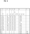
- Fig. 6 provides a table of angles ⁇ 1, ⁇ 2, and ⁇ 3 (see columns 2 to 4), as well as a resulting ratio R1 (see column 5) and the sum of the three angles (see column 6).
- the ratio R1 is the ratio of the first angle ⁇ 1 to the third angle ⁇ 3.
- the dimensions and ratios are listed for twelve different sizes Bi, as specified in column 1. Rows 13 and 14 show the minimum and maximum values of column 6, respectively.
- the eight holes L of the drive flange 11 are arranged point-symmetrically on the drive flange 11 with respect to the center point M of the drive flange 11 and are also arranged symmetrically on the drive flange 11 with respect to the connecting line 40 and the transverse line 41. Therefore, the first angle ⁇ 1 is half the size of the third angle ⁇ 3, i.e., the ratio R1 is constantly 0.5.
- the angles specified are in value ranges selected in such a way that a hole pattern that is congruent for all gearbox housings is created, thereby increasing interchangeability and simplifying storage.
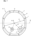
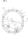
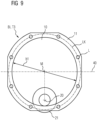
- Fig. 7 to 9 show schematic views of a drive flange 11 for gear housings of different types Tj, but the same size Bi.
- Fig. 7 shows a drive flange 11 of a gearbox housing of type T1 "spur gear".
- the circles drawn around the two lower axes 20 indicate the inner and outer diameters of the bearing location 21.
- the bearing triangle 22 formed by the axes 20 lies thus completely within the housing opening 10.
- Fig. 8 shows a drive flange 11 of a gearbox housing of type T2 "parallel gear".
- the circles drawn around the two lower axes 20 indicate the inner and outer diameters of the bearing point 21.
- the bearing triangle 22 formed by the axes 20 thus lies entirely within the housing opening 10.
- Fig. 9 shows a drive flange 11 of a gearbox housing of type T3 "bevel gear".
- the two circles drawn around the lower axis 20 indicate the inner and outer diameters of the bearing location 21.
Landscapes
- Engineering & Computer Science (AREA)
- General Engineering & Computer Science (AREA)
- Mechanical Engineering (AREA)
- General Details Of Gearings (AREA)
- Gear Transmission (AREA)
Claims (10)
- Gamme de carters ( Gij ) d'engrenage de tailles de construction ( Bi ) différentes,dans laquelle chaque taille de construction ( Bi ) comprend une série de types ( Tj ) de construction différents, qui sont appropriés à un engrenage cylindrique et à au moins un type d'engrenage des types suivants : engrenage conique, engrenage plat et engrenage à vis sans fin,dans laquelle chaque carter ( Gij ) d'engrenage a, du côté de l'entraînement, une ouverture ( 10 ) entourée d'une bride (11) d'entraînement pour le raccord d'un moteur, d'une plaque d'adaptateur ou d'un autre engrenage etdans laquelle, dans au moins deux tailles de construction ( Bi ) différentes, chacune pour au moins deux types ( Tj ) de construction différents, les axes ( 20 ), s'étendant perpendiculairement au plan de la bride ( 11 ) d'entraînement de points ( 21 ) de palier prévus pour la réception de palier ( 30 ) d'arbre pour des parties ( 31 ) de denture d'engrenage, se trouvant, quand on regarde perpendiculairement au plan ( 14 ) de la bride ( 11 ) d'entraînement, à l'intérieur d'un diamètre ( b1 ) intérieur minimum de la bride ( 11 ) d'entraînement,caractérisée en ce que, pour un type ( Tj ) de construction, approprié à un engrenage cylindrique, dans toutes les tailles de construction ( Bi ), un rapport ( QB ) d'un diamètre ( q1 ) extérieur minimum de la bride ( 11 ) d'entraînement à un diamètre ( b1 ) intérieur minimum de la bride ( 11 ) d'entraînement est dans une plage allant d'environ 1,07 à environ 1,21, en ce que la bride ( 11 ) d'entraînement a, sur deux côtés opposés, des méplats ( 12 ) du bord ( 13a ) extérieur, dont la distance l'un à l'autre définit le diamètre ( q1 ) extérieur minimum de la bride ( 11 ) d'entraînement et en ce que la bride ( 11 ) d'entraînement est sensiblement en forme d'anneau de cercle.
- Gamme suivant la revendication 1,
dans laquelle, dans au moins deux tailles de construction ( Bi ) différentes, respectivement pour tous les types ( Tj ) de construction, lesdits axes ( 20 ) se trouvent à l'intérieur du diamètre ( b1 ) intérieur minimum de la bride ( 11 ) d'entraînement. - Gamme suivant la revendication 1 ou 2,
dans laquelle, pour un type ( Tj ) de construction approprié à un engrenage cylindrique, dans toutes les dimensions ( Bi ), un rapport ( QC ) d'un diamètre ( a2 ) extérieur maximum de la bride ( 11 ) d'entraînement à une distance ( a1 ) entre les axes de points ( 21 ) de palier prévus pour la réception de paliers ( 30 ) d'arbre pour des parties ( 31 ) de denture d'un premier étage d'engrenage se trouve dans une plage allant d'environ 2,74 à environ 3,00. - Gamme suivant l'une des revendications précédentes,
dans laquelle, dans la bride ( 11 ) d'entraînement, sont pratiqués des perçages ( L ), qui sont sur un cercle ( LK ) de perçage d'un diamètre ( e1 ) et qui sont prévus pour la réception de vis d'assemblage et dans laquelle, pour un type ( Tj ) de construction approprié à un engrenage cylindrique, dans toutes les tailles de construction ( Bi ), un rapport ( QA ) d'un diamètre ( q1 ) extérieur minimum de la bride ( 11 ) d'entraînement au diamètre ( e1 ) du cercle de perçage est dans une plage allant d'environ 0,97 à environ 1,05. - Gamme suivant l'une des revendications précédentes,
dans laquelle la bride ( 11 ) d'entraînement a des perçages ( L ), qui sont prévus pour la réception de vis d'assemblage et qui sont disposés d'une manière symétrique par rapport à un point sur un cercle ( LK ) de perçage de diamètre ( e1 ). - Gamme suivant la revendication 5,
dans laquelle le cercle ( LK ) de perçage s'étend sur la bride ( 11) d'entraînement, d'une manière ininterrompue sur tout son pourtour. - Gamme suivant la revendication 5 ou 6,
dans laquelle la bride ( 11 ) d'entraînement, sensiblement en forme d'anneau de cercle, a, sur deux côtés opposés, des méplats ( 12 ) du bord ( 13a ) extérieur et, dans la bride ( 11 ) d'entraînement, sont pratiqués huit perçages ( L ), dans laquelle quatre perçages ( L ) sont pratiqués dans chaque moitié ( 11a, 11b ) de la bride ( 11 ) d'entraînement, séparés par une droite ( 40 ) de distance des méplats ( 12 ). - Gamme suivant l'une des revendications 5 à 7,
dans laquelle les perçages ( L ) sont disposés à l'extérieur de la droite de distance et symétriquement par rapport à celle-ci et à une droite ( 41 ) transversale, qui lui est perpendiculaire. - Gamme suivant l'une des revendications 7 et 8,dans laquelle les quatre perçages ( L ), disposés dans une moitié ( 11a, 11b ) de la bride, sont placés de manière à ce qu'un premier perçage ( L1 ) se trouve suivant un premier angle ( α1 ) par rapport à la droite ( 40 ) de distance, un deuxième perçage ( L2 ) dans un deuxième angle ( α2 ) par rapport au premier perçage ( L1 ) et un troisième perçage ( L3 ) dans un troisième angle ( α3 ) par rapport au deuxième perçage ( L2 ),dans laquelle les angles sont mesurés respectivement tels que vus à partir d'un centre ( M ) du cercle ( LK ) de perçage et dans laquelle un rapport ( R1 ) du premier angle ( α1 ) au troisième angle ( α3 ) est constant, en étant de préférence de ½ et une somme des trois angles est dans une plage allant de 112, 5 à 118,5.
- Engrenage, notamment engrenage cylindrique, engrenage conique, engrenage plat ou engrenage à vis sans fin, ayant un carter ( Gij ) d'engrenage provenant d'une gamme suivant l'une des revendications précédentes.
Priority Applications (1)
| Application Number | Priority Date | Filing Date | Title |
|---|---|---|---|
| EP13717468.6A EP2823200B2 (fr) | 2012-04-18 | 2013-04-10 | Gamme de boîtiers d'engrenage |
Applications Claiming Priority (3)
| Application Number | Priority Date | Filing Date | Title |
|---|---|---|---|
| EP12164624.4A EP2653752A1 (fr) | 2012-04-18 | 2012-04-18 | Gamme de boîtiers d'engrenage |
| EP13717468.6A EP2823200B2 (fr) | 2012-04-18 | 2013-04-10 | Gamme de boîtiers d'engrenage |
| PCT/EP2013/057426 WO2013156357A1 (fr) | 2012-04-18 | 2013-04-10 | Gamme de boîtiers d'engrenage |
Publications (3)
| Publication Number | Publication Date |
|---|---|
| EP2823200A1 EP2823200A1 (fr) | 2015-01-14 |
| EP2823200B1 EP2823200B1 (fr) | 2018-07-11 |
| EP2823200B2 true EP2823200B2 (fr) | 2025-05-07 |
Family
ID=48142751
Family Applications (2)
| Application Number | Title | Priority Date | Filing Date |
|---|---|---|---|
| EP12164624.4A Withdrawn EP2653752A1 (fr) | 2012-04-18 | 2012-04-18 | Gamme de boîtiers d'engrenage |
| EP13717468.6A Active EP2823200B2 (fr) | 2012-04-18 | 2013-04-10 | Gamme de boîtiers d'engrenage |
Family Applications Before (1)
| Application Number | Title | Priority Date | Filing Date |
|---|---|---|---|
| EP12164624.4A Withdrawn EP2653752A1 (fr) | 2012-04-18 | 2012-04-18 | Gamme de boîtiers d'engrenage |
Country Status (5)
| Country | Link |
|---|---|
| US (1) | US20150128759A1 (fr) |
| EP (2) | EP2653752A1 (fr) |
| CN (1) | CN104246308B (fr) |
| ES (1) | ES2690588T5 (fr) |
| WO (1) | WO2013156357A1 (fr) |
Families Citing this family (5)
| Publication number | Priority date | Publication date | Assignee | Title |
|---|---|---|---|---|
| JP6088395B2 (ja) * | 2013-10-10 | 2017-03-01 | 住友重機械工業株式会社 | 減速装置のシリーズ |
| EP3827185B1 (fr) * | 2018-07-24 | 2022-11-30 | Sew-Eurodrive GmbH & Co. KG | Moto-réducteur |
| EP3827184B1 (fr) * | 2018-07-24 | 2023-01-25 | Sew-Eurodrive GmbH & Co. KG | Moto-réducteur |
| DE102021003133A1 (de) * | 2020-07-21 | 2022-01-27 | Sew-Eurodrive Gmbh & Co Kg | Getriebemotor mit Getriebe, welches eine eintreibende Welle und ein Gehäuse aufweist |
| CN113958694A (zh) * | 2020-07-21 | 2022-01-21 | Sew-传动设备(天津)有限公司 | 包括具有输入轴和壳体的减速器的减速电机 |
Citations (1)
| Publication number | Priority date | Publication date | Assignee | Title |
|---|---|---|---|---|
| EP1610031B1 (fr) † | 2004-06-22 | 2008-10-15 | A. Friedr. Flender Ag | Transmission à engrenages droits |
Family Cites Families (8)
| Publication number | Priority date | Publication date | Assignee | Title |
|---|---|---|---|---|
| BE491931A (fr) * | 1949-10-31 | |||
| DE1203075B (de) * | 1959-12-16 | 1965-10-14 | Zd Y V I Narodni Podnik | Getriebegehaeuse |
| DE1284804B (de) * | 1964-04-18 | 1968-12-05 | Wuelfel Eisenwerk | Zweiteiliges Getriebegehaeuse |
| DE9010311U1 (de) * | 1990-07-07 | 1990-10-04 | Stöber Antriebstechnik GmbH & Co, 7530 Pforzheim | Getriebegehäuse, insbesondere für Stirnrad/Kegelrad- oder Kegelradgetriebe |
| ES2184570B1 (es) * | 2000-08-10 | 2004-06-16 | Francisco J. Domenech Diaz-Calderon | Caja-carcasa universal para reductores de velocidad. |
| JP4520657B2 (ja) * | 2001-03-29 | 2010-08-11 | 住友重機械工業株式会社 | 減速装置シリーズ、モータ取付用のアダプタ |
| EP3165796B1 (fr) * | 2003-02-28 | 2019-04-10 | Sew-Eurodrive GmbH & Co. KG | Moto-reducteur |
| DE10312941B4 (de) * | 2003-02-28 | 2019-08-01 | Sew-Eurodrive Gmbh & Co Kg | Bausatz für eine Baureihe von Getriebemotoren |
-
2012
- 2012-04-18 EP EP12164624.4A patent/EP2653752A1/fr not_active Withdrawn
-
2013
- 2013-04-10 US US14/395,317 patent/US20150128759A1/en not_active Abandoned
- 2013-04-10 ES ES13717468T patent/ES2690588T5/es active Active
- 2013-04-10 CN CN201380020599.9A patent/CN104246308B/zh active Active
- 2013-04-10 EP EP13717468.6A patent/EP2823200B2/fr active Active
- 2013-04-10 WO PCT/EP2013/057426 patent/WO2013156357A1/fr not_active Ceased
Patent Citations (1)
| Publication number | Priority date | Publication date | Assignee | Title |
|---|---|---|---|---|
| EP1610031B1 (fr) † | 2004-06-22 | 2008-10-15 | A. Friedr. Flender Ag | Transmission à engrenages droits |
Also Published As
| Publication number | Publication date |
|---|---|
| EP2823200A1 (fr) | 2015-01-14 |
| CN104246308A (zh) | 2014-12-24 |
| US20150128759A1 (en) | 2015-05-14 |
| CN104246308B (zh) | 2018-01-12 |
| EP2653752A1 (fr) | 2013-10-23 |
| ES2690588T3 (es) | 2018-11-21 |
| WO2013156357A1 (fr) | 2013-10-24 |
| ES2690588T5 (en) | 2025-10-07 |
| EP2823200B1 (fr) | 2018-07-11 |
Similar Documents
| Publication | Publication Date | Title |
|---|---|---|
| EP0981697B1 (fr) | Boite planetaire | |
| EP2823200B2 (fr) | Gamme de boîtiers d'engrenage | |
| EP2177789B1 (fr) | Mécanisme de commande doté d'un moteur électrique et d'un train épicycloïdal | |
| EP1266153A1 (fr) | Systeme modulaire d'engrenage | |
| DE202012009415U1 (de) | Industriegetriebe | |
| EP2431632B1 (fr) | Engrenage à puissance dérivée pour une éolienne | |
| DE102015223543B4 (de) | Planetengetriebe für eine Windkraftanlage mit Ölzuführmitteln zur Druckölschmierung einer Planetenstufenverzahnung | |
| DE102007058904B4 (de) | Winkelgetriebe und Baureihe von solchen Winkelgetrieben | |
| EP1525413B1 (fr) | Engrenage conique et notamment hypoide | |
| DE102014102403B4 (de) | Explosionsgeschützter Kreuzendschalter | |
| EP2066919B1 (fr) | Démultiplicateur à phase multiple | |
| WO2019179869A1 (fr) | Engrenage planétaire pourvu d'un pignon planétaire à une dent ayant une denture évoloïde | |
| DE102014014575B4 (de) | Untersetzungsgetriebe | |
| WO2020148174A1 (fr) | Entraînement pour une porte-tambour rotative | |
| EP3513100B1 (fr) | Motoréducteur angulaire | |
| DE112018005739T5 (de) | Schneckengetriebeeinheit, Getriebe, Getriebemotor und elektrische Vorrichtung, die einen Getriebemotor aufweist | |
| EP1781965B1 (fr) | Carter, boite de vitesses et systeme modulaire de boites de vitesses | |
| DE102010007929A1 (de) | Abtriebsseitige Baugruppe eines Mühlenantriebssystems und Mühlenantriebssystem | |
| EP0838145A1 (fr) | Engrenage angulaire | |
| EP1932227B1 (fr) | Liaison par bride et electroreducteur | |
| DE102016216785B4 (de) | Umlaufrädergetriebe, insbesondere Reduktionsgetriebe mit integriertem Stirnraddifferential | |
| DE102009006482A1 (de) | Getriebe mit Gegenlager | |
| DE10320290B3 (de) | Getriebe | |
| DE102005063570B4 (de) | Gehäuse, Getriebe und Getriebebaukasten | |
| EP4707641A1 (fr) | Engrenage planétaire avec roues planétaires montées axialement glissantes |
Legal Events
| Date | Code | Title | Description |
|---|---|---|---|
| PUAI | Public reference made under article 153(3) epc to a published international application that has entered the european phase |
Free format text: ORIGINAL CODE: 0009012 |
|
| 17P | Request for examination filed |
Effective date: 20141010 |
|
| AK | Designated contracting states |
Kind code of ref document: A1 Designated state(s): AL AT BE BG CH CY CZ DE DK EE ES FI FR GB GR HR HU IE IS IT LI LT LU LV MC MK MT NL NO PL PT RO RS SE SI SK SM TR |
|
| AX | Request for extension of the european patent |
Extension state: BA ME |
|
| DAX | Request for extension of the european patent (deleted) | ||
| 17Q | First examination report despatched |
Effective date: 20151020 |
|
| STAA | Information on the status of an ep patent application or granted ep patent |
Free format text: STATUS: EXAMINATION IS IN PROGRESS |
|
| RAP1 | Party data changed (applicant data changed or rights of an application transferred) |
Owner name: SIEMENS AKTIENGESELLSCHAFT |
|
| GRAP | Despatch of communication of intention to grant a patent |
Free format text: ORIGINAL CODE: EPIDOSNIGR1 |
|
| STAA | Information on the status of an ep patent application or granted ep patent |
Free format text: STATUS: GRANT OF PATENT IS INTENDED |
|
| INTG | Intention to grant announced |
Effective date: 20180306 |
|
| GRAS | Grant fee paid |
Free format text: ORIGINAL CODE: EPIDOSNIGR3 |
|
| GRAA | (expected) grant |
Free format text: ORIGINAL CODE: 0009210 |
|
| STAA | Information on the status of an ep patent application or granted ep patent |
Free format text: STATUS: THE PATENT HAS BEEN GRANTED |
|
| AK | Designated contracting states |
Kind code of ref document: B1 Designated state(s): AL AT BE BG CH CY CZ DE DK EE ES FI FR GB GR HR HU IE IS IT LI LT LU LV MC MK MT NL NO PL PT RO RS SE SI SK SM TR |
|
| REG | Reference to a national code |
Ref country code: GB Ref legal event code: FG4D Free format text: NOT ENGLISH |
|
| REG | Reference to a national code |
Ref country code: CH Ref legal event code: EP |
|
| REG | Reference to a national code |
Ref country code: AT Ref legal event code: REF Ref document number: 1017215 Country of ref document: AT Kind code of ref document: T Effective date: 20180715 |
|
| REG | Reference to a national code |
Ref country code: IE Ref legal event code: FG4D Free format text: LANGUAGE OF EP DOCUMENT: GERMAN |
|
| REG | Reference to a national code |
Ref country code: DE Ref legal event code: R096 Ref document number: 502013010585 Country of ref document: DE |
|
| REG | Reference to a national code |
Ref country code: NL Ref legal event code: MP Effective date: 20180711 |
|
| REG | Reference to a national code |
Ref country code: ES Ref legal event code: FG2A Ref document number: 2690588 Country of ref document: ES Kind code of ref document: T3 Effective date: 20181121 |
|
| REG | Reference to a national code |
Ref country code: LT Ref legal event code: MG4D |
|
| PG25 | Lapsed in a contracting state [announced via postgrant information from national office to epo] |
Ref country code: NL Free format text: LAPSE BECAUSE OF FAILURE TO SUBMIT A TRANSLATION OF THE DESCRIPTION OR TO PAY THE FEE WITHIN THE PRESCRIBED TIME-LIMIT Effective date: 20180711 |
|
| PG25 | Lapsed in a contracting state [announced via postgrant information from national office to epo] |
Ref country code: PL Free format text: LAPSE BECAUSE OF FAILURE TO SUBMIT A TRANSLATION OF THE DESCRIPTION OR TO PAY THE FEE WITHIN THE PRESCRIBED TIME-LIMIT Effective date: 20180711 Ref country code: SE Free format text: LAPSE BECAUSE OF FAILURE TO SUBMIT A TRANSLATION OF THE DESCRIPTION OR TO PAY THE FEE WITHIN THE PRESCRIBED TIME-LIMIT Effective date: 20180711 Ref country code: BG Free format text: LAPSE BECAUSE OF FAILURE TO SUBMIT A TRANSLATION OF THE DESCRIPTION OR TO PAY THE FEE WITHIN THE PRESCRIBED TIME-LIMIT Effective date: 20181011 Ref country code: IS Free format text: LAPSE BECAUSE OF FAILURE TO SUBMIT A TRANSLATION OF THE DESCRIPTION OR TO PAY THE FEE WITHIN THE PRESCRIBED TIME-LIMIT Effective date: 20181111 Ref country code: NO Free format text: LAPSE BECAUSE OF FAILURE TO SUBMIT A TRANSLATION OF THE DESCRIPTION OR TO PAY THE FEE WITHIN THE PRESCRIBED TIME-LIMIT Effective date: 20181011 Ref country code: LT Free format text: LAPSE BECAUSE OF FAILURE TO SUBMIT A TRANSLATION OF THE DESCRIPTION OR TO PAY THE FEE WITHIN THE PRESCRIBED TIME-LIMIT Effective date: 20180711 Ref country code: GR Free format text: LAPSE BECAUSE OF FAILURE TO SUBMIT A TRANSLATION OF THE DESCRIPTION OR TO PAY THE FEE WITHIN THE PRESCRIBED TIME-LIMIT Effective date: 20181012 Ref country code: RS Free format text: LAPSE BECAUSE OF FAILURE TO SUBMIT A TRANSLATION OF THE DESCRIPTION OR TO PAY THE FEE WITHIN THE PRESCRIBED TIME-LIMIT Effective date: 20180711 |
|
| PG25 | Lapsed in a contracting state [announced via postgrant information from national office to epo] |
Ref country code: HR Free format text: LAPSE BECAUSE OF FAILURE TO SUBMIT A TRANSLATION OF THE DESCRIPTION OR TO PAY THE FEE WITHIN THE PRESCRIBED TIME-LIMIT Effective date: 20180711 Ref country code: LV Free format text: LAPSE BECAUSE OF FAILURE TO SUBMIT A TRANSLATION OF THE DESCRIPTION OR TO PAY THE FEE WITHIN THE PRESCRIBED TIME-LIMIT Effective date: 20180711 Ref country code: AL Free format text: LAPSE BECAUSE OF FAILURE TO SUBMIT A TRANSLATION OF THE DESCRIPTION OR TO PAY THE FEE WITHIN THE PRESCRIBED TIME-LIMIT Effective date: 20180711 |
|
| REG | Reference to a national code |
Ref country code: DE Ref legal event code: R026 Ref document number: 502013010585 Country of ref document: DE |
|
| PLBI | Opposition filed |
Free format text: ORIGINAL CODE: 0009260 |
|
| PLAX | Notice of opposition and request to file observation + time limit sent |
Free format text: ORIGINAL CODE: EPIDOSNOBS2 |
|
| PG25 | Lapsed in a contracting state [announced via postgrant information from national office to epo] |
Ref country code: CZ Free format text: LAPSE BECAUSE OF FAILURE TO SUBMIT A TRANSLATION OF THE DESCRIPTION OR TO PAY THE FEE WITHIN THE PRESCRIBED TIME-LIMIT Effective date: 20180711 Ref country code: EE Free format text: LAPSE BECAUSE OF FAILURE TO SUBMIT A TRANSLATION OF THE DESCRIPTION OR TO PAY THE FEE WITHIN THE PRESCRIBED TIME-LIMIT Effective date: 20180711 Ref country code: RO Free format text: LAPSE BECAUSE OF FAILURE TO SUBMIT A TRANSLATION OF THE DESCRIPTION OR TO PAY THE FEE WITHIN THE PRESCRIBED TIME-LIMIT Effective date: 20180711 |
|
| 26 | Opposition filed |
Opponent name: SEW-EURODRIVE GMBH & CO. KG Effective date: 20190404 |
|
| PG25 | Lapsed in a contracting state [announced via postgrant information from national office to epo] |
Ref country code: SM Free format text: LAPSE BECAUSE OF FAILURE TO SUBMIT A TRANSLATION OF THE DESCRIPTION OR TO PAY THE FEE WITHIN THE PRESCRIBED TIME-LIMIT Effective date: 20180711 Ref country code: DK Free format text: LAPSE BECAUSE OF FAILURE TO SUBMIT A TRANSLATION OF THE DESCRIPTION OR TO PAY THE FEE WITHIN THE PRESCRIBED TIME-LIMIT Effective date: 20180711 Ref country code: SK Free format text: LAPSE BECAUSE OF FAILURE TO SUBMIT A TRANSLATION OF THE DESCRIPTION OR TO PAY THE FEE WITHIN THE PRESCRIBED TIME-LIMIT Effective date: 20180711 |
|
| PG25 | Lapsed in a contracting state [announced via postgrant information from national office to epo] |
Ref country code: SI Free format text: LAPSE BECAUSE OF FAILURE TO SUBMIT A TRANSLATION OF THE DESCRIPTION OR TO PAY THE FEE WITHIN THE PRESCRIBED TIME-LIMIT Effective date: 20180711 |
|
| PLBB | Reply of patent proprietor to notice(s) of opposition received |
Free format text: ORIGINAL CODE: EPIDOSNOBS3 |
|
| REG | Reference to a national code |
Ref country code: CH Ref legal event code: PL |
|
| PG25 | Lapsed in a contracting state [announced via postgrant information from national office to epo] |
Ref country code: LU Free format text: LAPSE BECAUSE OF NON-PAYMENT OF DUE FEES Effective date: 20190410 Ref country code: MC Free format text: LAPSE BECAUSE OF FAILURE TO SUBMIT A TRANSLATION OF THE DESCRIPTION OR TO PAY THE FEE WITHIN THE PRESCRIBED TIME-LIMIT Effective date: 20180711 |
|
| PG25 | Lapsed in a contracting state [announced via postgrant information from national office to epo] |
Ref country code: LI Free format text: LAPSE BECAUSE OF NON-PAYMENT OF DUE FEES Effective date: 20190430 Ref country code: CH Free format text: LAPSE BECAUSE OF NON-PAYMENT OF DUE FEES Effective date: 20190430 |
|
| PG25 | Lapsed in a contracting state [announced via postgrant information from national office to epo] |
Ref country code: IE Free format text: LAPSE BECAUSE OF NON-PAYMENT OF DUE FEES Effective date: 20190410 |
|
| PG25 | Lapsed in a contracting state [announced via postgrant information from national office to epo] |
Ref country code: PT Free format text: LAPSE BECAUSE OF FAILURE TO SUBMIT A TRANSLATION OF THE DESCRIPTION OR TO PAY THE FEE WITHIN THE PRESCRIBED TIME-LIMIT Effective date: 20181111 |
|
| REG | Reference to a national code |
Ref country code: AT Ref legal event code: MM01 Ref document number: 1017215 Country of ref document: AT Kind code of ref document: T Effective date: 20190410 |
|
| PG25 | Lapsed in a contracting state [announced via postgrant information from national office to epo] |
Ref country code: AT Free format text: LAPSE BECAUSE OF NON-PAYMENT OF DUE FEES Effective date: 20190410 |
|
| PG25 | Lapsed in a contracting state [announced via postgrant information from national office to epo] |
Ref country code: CY Free format text: LAPSE BECAUSE OF FAILURE TO SUBMIT A TRANSLATION OF THE DESCRIPTION OR TO PAY THE FEE WITHIN THE PRESCRIBED TIME-LIMIT Effective date: 20180711 |
|
| PG25 | Lapsed in a contracting state [announced via postgrant information from national office to epo] |
Ref country code: HU Free format text: LAPSE BECAUSE OF FAILURE TO SUBMIT A TRANSLATION OF THE DESCRIPTION OR TO PAY THE FEE WITHIN THE PRESCRIBED TIME-LIMIT; INVALID AB INITIO Effective date: 20130410 Ref country code: MT Free format text: LAPSE BECAUSE OF FAILURE TO SUBMIT A TRANSLATION OF THE DESCRIPTION OR TO PAY THE FEE WITHIN THE PRESCRIBED TIME-LIMIT Effective date: 20180711 |
|
| PGFP | Annual fee paid to national office [announced via postgrant information from national office to epo] |
Ref country code: FI Payment date: 20210421 Year of fee payment: 9 |
|
| PGFP | Annual fee paid to national office [announced via postgrant information from national office to epo] |
Ref country code: TR Payment date: 20210407 Year of fee payment: 9 Ref country code: BE Payment date: 20210420 Year of fee payment: 9 |
|
| APBM | Appeal reference recorded |
Free format text: ORIGINAL CODE: EPIDOSNREFNO |
|
| APBP | Date of receipt of notice of appeal recorded |
Free format text: ORIGINAL CODE: EPIDOSNNOA2O |
|
| APAH | Appeal reference modified |
Free format text: ORIGINAL CODE: EPIDOSCREFNO |
|
| APBQ | Date of receipt of statement of grounds of appeal recorded |
Free format text: ORIGINAL CODE: EPIDOSNNOA3O |
|
| PG25 | Lapsed in a contracting state [announced via postgrant information from national office to epo] |
Ref country code: MK Free format text: LAPSE BECAUSE OF FAILURE TO SUBMIT A TRANSLATION OF THE DESCRIPTION OR TO PAY THE FEE WITHIN THE PRESCRIBED TIME-LIMIT Effective date: 20180711 |
|
| REG | Reference to a national code |
Ref country code: BE Ref legal event code: MM Effective date: 20220430 |
|
| PG25 | Lapsed in a contracting state [announced via postgrant information from national office to epo] |
Ref country code: FI Free format text: LAPSE BECAUSE OF NON-PAYMENT OF DUE FEES Effective date: 20220410 |
|
| PG25 | Lapsed in a contracting state [announced via postgrant information from national office to epo] |
Ref country code: BE Free format text: LAPSE BECAUSE OF NON-PAYMENT OF DUE FEES Effective date: 20220430 |
|
| REG | Reference to a national code |
Ref country code: GB Ref legal event code: 732E Free format text: REGISTERED BETWEEN 20231123 AND 20231129 |
|
| RAP2 | Party data changed (patent owner data changed or rights of a patent transferred) |
Owner name: INNOMOTICS GMBH |
|
| APBU | Appeal procedure closed |
Free format text: ORIGINAL CODE: EPIDOSNNOA9O |
|
| REG | Reference to a national code |
Ref country code: CH Ref legal event code: PK Free format text: BERICHTIGUNGEN |
|
| RIN2 | Information on inventor provided after grant (corrected) |
Inventor name: STOLL, ROBERT Inventor name: SCHNURR, WOLFGANG |
|
| PUAH | Patent maintained in amended form |
Free format text: ORIGINAL CODE: 0009272 |
|
| STAA | Information on the status of an ep patent application or granted ep patent |
Free format text: STATUS: PATENT MAINTAINED AS AMENDED |
|
| PGFP | Annual fee paid to national office [announced via postgrant information from national office to epo] |
Ref country code: FR Payment date: 20250327 Year of fee payment: 13 |
|
| PGFP | Annual fee paid to national office [announced via postgrant information from national office to epo] |
Ref country code: GB Payment date: 20250326 Year of fee payment: 13 |
|
| 27A | Patent maintained in amended form |
Effective date: 20250507 |
|
| AK | Designated contracting states |
Kind code of ref document: B2 Designated state(s): AL AT BE BG CH CY CZ DE DK EE ES FI FR GB GR HR HU IE IS IT LI LT LU LV MC MK MT NL NO PL PT RO RS SE SI SK SM TR |
|
| REG | Reference to a national code |
Ref country code: DE Ref legal event code: R102 Ref document number: 502013010585 Country of ref document: DE |
|
| PGFP | Annual fee paid to national office [announced via postgrant information from national office to epo] |
Ref country code: DE Payment date: 20250429 Year of fee payment: 13 |
|
| PGFP | Annual fee paid to national office [announced via postgrant information from national office to epo] |
Ref country code: ES Payment date: 20250513 Year of fee payment: 13 |
|
| PGFP | Annual fee paid to national office [announced via postgrant information from national office to epo] |
Ref country code: IT Payment date: 20250327 Year of fee payment: 13 |
|
| REG | Reference to a national code |
Ref country code: DE Ref legal event code: R081 Ref document number: 502013010585 Country of ref document: DE Owner name: INNOMOTICS GMBH, DE Free format text: FORMER OWNER: SIEMENS AKTIENGESELLSCHAFT, 80333 MUENCHEN, DE |
|
| REG | Reference to a national code |
Ref country code: ES Ref legal event code: DC2A Ref document number: 2690588 Country of ref document: ES Kind code of ref document: T5 Effective date: 20251007 |