EP2823501B1 - Systèmes de radiothérapie pluridirectionnelle à très haute énergie d'électrons - Google Patents
Systèmes de radiothérapie pluridirectionnelle à très haute énergie d'électrons Download PDFInfo
- Publication number
- EP2823501B1 EP2823501B1 EP13757604.7A EP13757604A EP2823501B1 EP 2823501 B1 EP2823501 B1 EP 2823501B1 EP 13757604 A EP13757604 A EP 13757604A EP 2823501 B1 EP2823501 B1 EP 2823501B1
- Authority
- EP
- European Patent Office
- Prior art keywords
- targeted tissue
- beams
- directions
- dose
- mev
- Prior art date
- Legal status (The legal status is an assumption and is not a legal conclusion. Google has not performed a legal analysis and makes no representation as to the accuracy of the status listed.)
- Active
Links
Images





Classifications
-
- A—HUMAN NECESSITIES
- A61—MEDICAL OR VETERINARY SCIENCE; HYGIENE
- A61N—ELECTROTHERAPY; MAGNETOTHERAPY; RADIATION THERAPY; ULTRASOUND THERAPY
- A61N5/00—Radiation therapy
- A61N5/10—X-ray therapy; Gamma-ray therapy; Particle-irradiation therapy
- A61N5/1048—Monitoring, verifying, controlling systems and methods
- A61N5/1064—Monitoring, verifying, controlling systems and methods for adjusting radiation treatment in response to monitoring
-
- A—HUMAN NECESSITIES
- A61—MEDICAL OR VETERINARY SCIENCE; HYGIENE
- A61N—ELECTROTHERAPY; MAGNETOTHERAPY; RADIATION THERAPY; ULTRASOUND THERAPY
- A61N5/00—Radiation therapy
- A61N5/10—X-ray therapy; Gamma-ray therapy; Particle-irradiation therapy
- A61N5/1042—X-ray therapy; Gamma-ray therapy; Particle-irradiation therapy with spatial modulation of the radiation beam within the treatment head
- A61N5/1043—Scanning the radiation beam, e.g. spot scanning or raster scanning
-
- A—HUMAN NECESSITIES
- A61—MEDICAL OR VETERINARY SCIENCE; HYGIENE
- A61N—ELECTROTHERAPY; MAGNETOTHERAPY; RADIATION THERAPY; ULTRASOUND THERAPY
- A61N5/00—Radiation therapy
- A61N5/10—X-ray therapy; Gamma-ray therapy; Particle-irradiation therapy
- A61N5/1048—Monitoring, verifying, controlling systems and methods
- A61N5/1064—Monitoring, verifying, controlling systems and methods for adjusting radiation treatment in response to monitoring
- A61N5/1065—Beam adjustment
-
- A—HUMAN NECESSITIES
- A61—MEDICAL OR VETERINARY SCIENCE; HYGIENE
- A61N—ELECTROTHERAPY; MAGNETOTHERAPY; RADIATION THERAPY; ULTRASOUND THERAPY
- A61N5/00—Radiation therapy
- A61N5/10—X-ray therapy; Gamma-ray therapy; Particle-irradiation therapy
- A61N5/1077—Beam delivery systems
- A61N5/1081—Rotating beam systems with a specific mechanical construction, e.g. gantries
-
- A—HUMAN NECESSITIES
- A61—MEDICAL OR VETERINARY SCIENCE; HYGIENE
- A61N—ELECTROTHERAPY; MAGNETOTHERAPY; RADIATION THERAPY; ULTRASOUND THERAPY
- A61N5/00—Radiation therapy
- A61N5/10—X-ray therapy; Gamma-ray therapy; Particle-irradiation therapy
- A61N5/1048—Monitoring, verifying, controlling systems and methods
- A61N5/1049—Monitoring, verifying, controlling systems and methods for verifying the position of the patient with respect to the radiation beam
- A61N2005/1051—Monitoring, verifying, controlling systems and methods for verifying the position of the patient with respect to the radiation beam using an active marker
-
- A—HUMAN NECESSITIES
- A61—MEDICAL OR VETERINARY SCIENCE; HYGIENE
- A61N—ELECTROTHERAPY; MAGNETOTHERAPY; RADIATION THERAPY; ULTRASOUND THERAPY
- A61N5/00—Radiation therapy
- A61N5/10—X-ray therapy; Gamma-ray therapy; Particle-irradiation therapy
- A61N5/1048—Monitoring, verifying, controlling systems and methods
- A61N5/1049—Monitoring, verifying, controlling systems and methods for verifying the position of the patient with respect to the radiation beam
- A61N2005/1058—Monitoring, verifying, controlling systems and methods for verifying the position of the patient with respect to the radiation beam using ultrasound imaging
-
- A—HUMAN NECESSITIES
- A61—MEDICAL OR VETERINARY SCIENCE; HYGIENE
- A61N—ELECTROTHERAPY; MAGNETOTHERAPY; RADIATION THERAPY; ULTRASOUND THERAPY
- A61N5/00—Radiation therapy
- A61N5/10—X-ray therapy; Gamma-ray therapy; Particle-irradiation therapy
- A61N5/1048—Monitoring, verifying, controlling systems and methods
- A61N5/1049—Monitoring, verifying, controlling systems and methods for verifying the position of the patient with respect to the radiation beam
- A61N2005/1061—Monitoring, verifying, controlling systems and methods for verifying the position of the patient with respect to the radiation beam using an x-ray imaging system having a separate imaging source
-
- A—HUMAN NECESSITIES
- A61—MEDICAL OR VETERINARY SCIENCE; HYGIENE
- A61N—ELECTROTHERAPY; MAGNETOTHERAPY; RADIATION THERAPY; ULTRASOUND THERAPY
- A61N5/00—Radiation therapy
- A61N5/10—X-ray therapy; Gamma-ray therapy; Particle-irradiation therapy
- A61N5/1048—Monitoring, verifying, controlling systems and methods
- A61N5/1075—Monitoring, verifying, controlling systems and methods for testing, calibrating, or quality assurance of the radiation treatment apparatus
- A61N2005/1076—Monitoring, verifying, controlling systems and methods for testing, calibrating, or quality assurance of the radiation treatment apparatus using a dummy object placed in the radiation field, e.g. phantom
-
- A—HUMAN NECESSITIES
- A61—MEDICAL OR VETERINARY SCIENCE; HYGIENE
- A61N—ELECTROTHERAPY; MAGNETOTHERAPY; RADIATION THERAPY; ULTRASOUND THERAPY
- A61N5/00—Radiation therapy
- A61N5/10—X-ray therapy; Gamma-ray therapy; Particle-irradiation therapy
- A61N2005/1085—X-ray therapy; Gamma-ray therapy; Particle-irradiation therapy characterised by the type of particles applied to the patient
- A61N2005/1087—Ions; Protons
- A61N2005/1088—Ions; Protons generated by laser radiation
-
- A—HUMAN NECESSITIES
- A61—MEDICAL OR VETERINARY SCIENCE; HYGIENE
- A61N—ELECTROTHERAPY; MAGNETOTHERAPY; RADIATION THERAPY; ULTRASOUND THERAPY
- A61N5/00—Radiation therapy
- A61N5/10—X-ray therapy; Gamma-ray therapy; Particle-irradiation therapy
- A61N2005/1085—X-ray therapy; Gamma-ray therapy; Particle-irradiation therapy characterised by the type of particles applied to the patient
- A61N2005/1089—Electrons
-
- G—PHYSICS
- G21—NUCLEAR PHYSICS; NUCLEAR ENGINEERING
- G21K—HANDLING OF PARTICLES OR IONISING RADIATION NOT OTHERWISE PROVIDED FOR; IRRADIATION DEVICES; GAMMA RAY OR X-RAY MICROSCOPES
- G21K5/00—Irradiation devices
- G21K5/04—Irradiation devices with beam-forming means
Definitions
- the disclosure generally relates to radiation therapy and more particularly to systems and methods for very high electron energy radiation therapy.
- IMRT intensity modulated radiation therapy
- IGRT image guided radiation therapy
- SABR stereotactic ablative radiotherapy
- SBRT stereotactic body radiotherapy
- US2008/0298401 describes a device and method for creating a spatial dose distribution in a medium volume.
- a laser system produces laser pulses with a pulse length shorter than 200 femtoseconds and is capable of being focused to peak intensities greater than 1018W/cm2.
- An electron source is capable of releasing a high-energy electron pulse, in particular with the electrons having an energy greater than 100 MeV, upon irradiation with said laser pulses propagating into the medium volume.
- Light paths of at least some of the laser pulses are adjustable in such a way that that high-energy electron pulses are emitted from the irradiated at least one electron source on different trajectories through the medium volume thereby depositing their dose in the medium volume according to a provided pattern.
- US4,726,046 describes a radiotherapy machine including a microwave powered accelerator that produces an energetic beam of charged particles, bending and focusing magnets to parallel scan the beam in a plane and collimators to make the resulting parallel scanned beam into paraxial rays of charged particles or X-rays.
- the beam is intensity modulated as it is scanned to control the dosage spatial distribution.
- US2004/0079899 describes a device for generating helical electron beams for use in radiation therapy.
- the device contains a tertiary collimating cone that can be attached to a gantry of a linear accelerator or placed directly below the gantry.
- the tertiary collimating cone has a dynamic energy compensator and a magnetic electron collimator to modify the energy of electrons and to generate a helical trajectory.
- a multileaf collimator may be present within the tertiary collimating cone.
- a computer coordinates the movement of the various components.
- US7,835,492 describes a medical accelerator system for simultaneous radiation therapy to all treatment fields. Single or four beam S-band, C-band or X-band accelerators are connected to treatment heads through connecting beam lines.
- US 7835492 provides a medical accelerator system for simultaneous radiation therapy to all treatment fields. It provides the single dose effect of radiation on cell survival. It eliminates the inter-field interrupted, subfractionated fractionated radiation therapy.
- Single or four beams S-band, C-band or X-band accelerators are connected to treatment heads through connecting beam lines. It is placed in a radiation shielding vault which minimizes the leakage and scattered radiation and the size and weight of the treatment head.
- treatment heads are arranged circularly and connected with the beam line.
- a pair of treatment heads is mounted to each ends of narrow gantries and multiple such treatment heads mounted gantries are assembled together. Electron beam is steered to all the treatment heads simultaneously to treat all the fields simultaneously.
- Radiating beam's intensity in a treatment field is modulated with combined divergent and pencil beam, selective beam's energy, dose rate and weight and not with MLC and similar devices. Since all the treatment fields are treated simultaneously the dose rate at the tumor site is the sum of each of the converging beam's dose rate at depth. It represents the biological dose rate. The dose rate at d-max for a given field is the individual machine dose rate. Its treatment options includes divergent or pencil beam modes. It enables to treat a tumor with lesser radiation toxicities to normal tissue and higher tumor cure and control.
- US 2010/207042 describes a particle beam treatment apparatus and respiration navigation apparatus used therefor.
- an accelerator more preferably a compact high-gradient, very high energy electron (VHEE) linear accelerator, which may be a standing wave linear accelerator, together with a delivery system capable of treating patients from multiple beam directions, potentially using all- electromagnetic or radiofrequency deflection steering is provided, that can deliver an entire dose or fraction of high-dose (e.g., 20-30 Gy) radiation therapy sufficiently fast to freeze physiologic motion, yet with a better degree of dose conformity or sculpting than conventional photon therapy.
- VHEE very high energy electron
- sufficiently fast to freeze physiologic motion means preferably faster than one human breath hold, less than 10 seconds, preferably less than 5 seconds, even more preferably less than one heartbeat and most preferably less than a second.
- Certain embodiments can also treat non - tumor targets, such as, by way of nonlimiting example, ablation or other treatment of: (1) nerves or facet joints for pain control; (2) foci in the brain for neuromodulation of neurologic conditions including pain, severe depression, and seizures; (3) portions of the lung with severe emphysema; and/or (4) abnormal conductive pathways in the heart to control refractory arrhythmias.
- non - tumor targets such as, by way of nonlimiting example, ablation or other treatment of: (1) nerves or facet joints for pain control; (2) foci in the brain for neuromodulation of neurologic conditions including pain, severe depression, and seizures; (3) portions of the lung with severe emphysema; and/or (4) abnormal conductive pathways in the heart to control refractory arrhythmias.
- a system for delivering very high electron energy beam to a target in a patient comprising:
- the controller is configured to receive information from an imaging device and use the information from the imaging device to control the directions in which the beam steering device steers the beam to the target.
- the accelerator is a linear accelerator capable of generating a beam having energy of between 1 and 250 Mev, more preferably 50 and 250 MeV and most preferably between 75 and 100 MeV.
- the time period is preferably faster than one human breath hold, more preferably less than 10 seconds, even more preferably less than 5 seconds, even more preferably less than one heartbeat and most preferably less than a second.
- the beam steering device is an electro-magnetic device.
- the beam steering device is a radiofrequency deflector device.
- the beam steering device includes a gantry, the gantry including multiple beam ports.
- the beam steering device includes a continuous annular gantry.
- the beam steering device is capable of providing thin pencil beam raster scanning.
- the beam steering system is capable of providing volume filling scanning.
- the beam steering device includes no mechanical moving parts.
- a system for delivering very high electron energy beam to a target in a patient comprising:
- the imaging device is capable of providing information to the controller to trigger when the system delivers the beam to the target.
- the system is capable of automatically delivering the beam to the target from multiple predetermined directions at multiple predetermined points in time.
- the accelerator is a linear accelerator capable of generating a beam having energy of between 1 and 250 Mev, more preferably 50 and 250 MeV and most preferably between 75 and 100 MeV.
- the time period is preferably faster than one human breath hold, more preferably less than 10 seconds, even more preferably less than 5 seconds, even more preferably less than one heartbeat and most preferably less than a second.
- the beam steering device is an electro-magnetic device.
- the beam steering device is a radiofrequency deflector device.
- the beam steering device includes no mechanical moving parts.
- a method for delivering a beam of very high electron energy to a target in a patient comprising:
- providing the system includes providing an accelerator that is capable of generating a beam having energy of between 1 and 250 Mev, more preferably 50 and 250 MeV and most preferably between 75 and 100 MeV.
- providing the system includes providing a controller capable of controlling length of time that the beam irradiates the target, the time period preferably faster than one human breath hold, more preferably less than 10 seconds, even more preferably less than 5 seconds, even more preferably less than one heartbeat and most preferably less than a second.
- providing the system includes providing a beam steering device that is an electro-magnetic device.
- providing the system includes providing a beam steering device that is a radiofrequency deflector device.
- providing the system includes providing a beam steering device that includes no mechanical moving parts.
- a controller that is configured to receive information from an imaging device and use the information from the imaging device to control the directions in which the beam steering device steers the beam to the target.
- an imaging device capable of generating images of the target and providing information from the imaging device to the controller to control the directions in which the beam steering device steers the beam to the target.
- providing the imaging device includes providing an imaging device that is capable of providing information to the controller to trigger when the system delivers the beam to the target.
- providing the imaging device includes providing an imaging device wherein, using information from the imaging device, the system is capable of automatically delivering the beam to the target from multiple predetermined directions at multiple predetermined points in time.
- a system for delivering a transverse-modulated electron beam to a target in a patient comprising:
- VHEE Very high-energy electrons
- MV megavoltage
- protons MV
- a compact high-gradient VHEE accelerator and delivery system is provided that is capable of treating patients from multiple beam directions with great speed, using electro-magnetic, radiofrequency deflection or other beam steering devices.
- Such embodiments may deliver an entire dose or fraction of high-dose radiation therapy sufficiently fast to freeze physiologic motion, yet with a better degree of dose conformity or sculpting, and decreased integral dose and consequently decreased risk of late toxicities and secondary malignancies, than the best MV photon therapy.
- Suitable energy ranges in accordance with certain embodiments of the disclosure are 1 - 250 MeV, more preferably 50 - 250 MeV, and most preferably 75 - 100 MeV.
- the term "sufficiently fast to freeze physiologic motion" in this document means preferably faster than one human breath hold, more preferably less than 10 seconds, even more preferably less than 5 seconds, even more preferably less than one heartbeat and most preferably less than a second.
- a major technological advance is extremely rapid or near instantaneous delivery of high dose radiotherapy that can eliminate the impact of target motion during RT, affording improved accuracy and dose conformity and potentially radiobiological effectiveness that will lead to improved clinical outcomes.
- Rapid imaging and treatment can also lead to greater clinical efficiency and patient throughput.
- the room occupancy time can be reduced to less than 5 minutes.
- Such advantages can be achieved, according to some embodiments, in a compact physical form factor and low cost comparable to conventional photon therapy systems, and much lower than hadron therapy systems.
- Figure 1 shows a system wherein beam access from a large number of axial directions is achieved by electromagnetic steering without moving parts or with a minimum of moving parts, for extremely fast highly conformal radiotherapy.
- the system shown in Figure 1 includes a compact linear accelerator, a beam steering device, and a controller for controlling the very high electron energy beam that is delivered to the patient.
- the embodiment can also include an integrated imaging device that obtains images of portions of the patient including the tumor or other site to be treated.
- the imaging device can also provide information to allow for control of the beam steering device in order to control directions from which the beam is delivered, and timing of the beam, among other variables.
- the prolonged treatment times of conventional highly conformal RT are sufficiently long for repair of sublethal chromosomal damage to occur during treatment, potentially reducing the tumoricidal effect of the radiation dose.
- the treatment times sufficiently fast to freeze physiologic motion that are made possible by certain embodiments of the disclosure may be more biologically effective, producing enhanced tumor cell killing for the same physical dose.
- Differences between certain embodiments of the disclosure and conventional photon therapy that impact biological effectiveness include a much faster delivery time and differences in the radiation quality.
- Some embodiments of the disclosure take advantage of the fact that electrons are relatively easier to manipulate using electric and magnetic fields.
- Charged particles such as electrons and protons can be produced as spatially coherent beams that can be steered electromagnetically or with radiofrequency deflection with high rapidity.
- direct treatment with scanned charged particle beams can eliminate the inefficiencies of Bremsstrahlung photon multiple beams from different directions toward the target in the patient.
- All conventional radiation therapy systems accomplish multidirectional treatment by mechanically rotating a gantry, or an entire compact linac, or even cyclotron, directing radiation to the target from one direction at a time.
- the beam must be deflected and then transported to the exit port and toward a target in or on the patient, such as a tumor in the patient.
- a target in or on the patient such as a tumor in the patient.
- the beam At the exit port the beam must be steered again to change the exit angle and/or beam size to adapt to the treatment plan.
- Electro- magnetic and/or RF deflector steering systems will manipulate the electron beam.
- a variety of gantry designs are potentially available, from simple to complex, ranging from multiple discrete beam ports arranged around the patient to a continuous annular gantry to allow arbitrary incident axial beam angles.
- the design depends on a number of factors, including scanning strategies such as thin pencil beam raster scanning vs. volume filling with non-isocentric variable-size shots, or use of transverse modulation of the electron beam profile.
- the steering system of the electron beam starts at the end of the accelerator structure with a two-dimensional deflector, which guides the beam into one of multiple channels. Once the beam enters a specific channel it is guided all the way to the exit of the channel, which is perpendicular to the axis of the patient. The guidance through the channels is achieved using low aberration electron optics. At the exit of each channel another small 2-D deflector can be added to scan the beam over a target. The number of channels can then be about 10 - 50. For a given channel width, a larger initial deflection would increase the number of channel entry ports that fit into the circumference swept by the beam. Thus if the field strength were increased, the number of channels could be increased to 100 or more.
- a linear accelerator will typically consume 50 to 100 MW of peak power to achieve 100 MeV of acceleration, over a length of 2 to 1 m respectively, potential RF deflectors can be considered. These have the advantage of being ultra- fast and permit capitalization on the RF infrastructure that is used for the main accelerator structure.
- the delivery system is preferably optimized to achieve high-dose treatment times sufficiently fast to freeze physiologic motion.
- Beam steering systems adopt a design that uses a smaller number of discrete beam channels, for example 3 - 10, that are mechanically rotated with the gantry around the patient.
- the initial deflector at the exit of the accelerator rapidly steers beams into the channels as they rotate.
- some advantages of this design include: arbitrary rotational angular resolution despite a fixed number of beam channels; reduced complexity and possibly cost given the smaller number of beam channels needed to achieve equivalent angular coverage; and the larger space between beam channels which makes it more straightforward to incorporate an x-ray source and detecting array for imaging, which when rotated provides integrated computed tomography imaging.
- the rate of mechanical rotation preferably provides full angular coverage sufficiently fast to freeze physiologic motion. The greater the number of beam channels, the less rotational speed required to meet this condition as a general matter.
- One innovation of certain embodiments of the disclosure is to eliminate mechanical gantry rotation, thus a beam steering system with no mechanical moving parts.
- One such embodiment is illustrated in Figure 1 , in which there is a gantry through which a charged particle beam is electromagnetically steered or steered using radiofrequency deflection to the target from any axial direction and a limited range of non-coplanar directions in addition.
- An alternative implementation is to use multiple discrete beam ports arranged radially around the patient, with the beam being steered through each of the ports to the target for multidirectional beam arrangements.
- Another alternative implementation is to have multiple accelerating structures, one for each of a set of beam ports arranged radially around the patient.
- Such novel treatment system geometries and steering systems can greatly enhance the treatment delivery speed of radiation therapy using any type of charged particle. Combining it with high-energy electrons in the 1-250 MeV range, more preferably the 50 - 250 MeV range, most preferably the 75 - 100 MeV range, has the following additional advantages: (1) Conformal dose distributions to both superficial and deep targets in patients superior to what can be achieved with conventional high- energy photon therapy; (2) Compactness of the source and power supply, which by using high-gradient accelerator designs such as those based wholly or partially on accelerators developed or in development at the SLAC National Accelerator Laboratory (SLAC) as described in Section C.iii below can accelerate electrons up to these energies in less than 2 meters; (3) Compactness of the gantry/beam ports compared to protons or ions because of the smaller electro-magnetic fields needed for electrons. This results in a system of comparable cost and physical size to existing conventional photon radiotherapy treatment systems, yet with better dose distributions and far faster dose delivery.
- SLAC National Accel
- an alternative embodiment is to incorporate in this geometry an array of high density targets and collimator grid in place of a single target I multi-leaf collimator combination, one per beam port in the case of discrete beam ports, or mounted on a rapidly rotating closed ring and targeted by the scanned electron beam in the case of an annular beam port, in order to produce rapidly scanned, multidirectional photon beams. While this approach may be subject to the inefficiency of Bremsstrahlung conversion, the speed limitations of conventional mechanical gantry and multi-leaf collimator motions may be essentially eliminated. The main potential advantage of this implementation is that existing commercial electron linacs in a lower energy range could be used as the source.
- certain embodiments of the disclsoure naturally facilitate rapid image-guidance to ensure accuracy.
- CT computed tomography
- Alternative embodiments can include integration of more conventional x-ray imaging or other imaging modalities, positron emission tomography and other options described in Section D.3 below.
- One approach in designing certain embodiments of the disclosure is to proceed using some or all of the following: (1) Monte Carlo simulations to determine optimal operating parameters; (2) experimental measurements of VHEE beams to validate and calibrate the Monte Carlo codes; (3) implementation factors for practical, cost-efficient and compact designs for the systems; and (4) experimental characterization of key radiobiological aspects and effects.
- VMAT SABR Volumetric Modulated Arc Therapy Stereotactic Ablative Body Radiotherapy
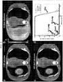
- Figure 2 shows axial images of simulation of SABR for an early stage lung tumor: dose distribution in an anthropomorphic phantom for a state-of-the-art 6 MV photon VMAT plan ( Figure 2a ), a conformal electron arc plan using currently available 20 MeV electron beam ( Figure 2b ), and a conformal electron arc plan using a 100 MeV electron beam as might be delivered by an embodiment of the disclsoure ( Figure 2c ).
- a graphical representation shows dose volume histogram ("DVH") of the planning target volume (“PTV”) (delineated in black in the axial images) and critical organs: DVHs for 6MV photons are shown in solid, 20 MeV electrons in dotted, and 100 MeV electrons in crossed lines ( Figure 2d ).
- DVDH dose volume histogram
- PTV planning target volume
- the plans were normalized to produce the same volumetric coverage of the PTV by the prescription dose. While conventional 20 MeV electrons results in poor conformity, the 100 MeV electron plan, even without optimization, is slightly more conformal than the 6 MV photon VMAT plan. Simulating conformal electron arcs across an energy range of 50-250 MeV ( Figures 2e, 2£ ) demonstrates that both the high (100%) and intermediate (50%) dose conformity indices (CI100% and CI50%) as well as the mean lung dose and total body integral dose are superior for electron energies of 80 MeV and higher for this selected clinical scenario. With inverse optimization, superior plans with even lower electron energies should be possible.
- the axial views of the dose distributions demonstrate that when all the plans are normalized to produce the same volumetric coverage of the target, the dose conformity of the 20 MeV beam is poor whereas the 100 MeV electron beam, even without inverse optimization, generates a dose distribution equivalent to the state-of-the-art 6MV photon beam VMAT plan.
- the DVH's of the target and critical structures for the three beams demonstrate slightly better sparing of critical structures with the 100 MeV electron plan compared to the 6 MV photon plan.
- the inventors experimentally measured the dose distribution and depth dose profiles at the NLCTA facility at SLAC.
- the NLCTA employs compact high- gradient linear accelerator structures which can produce beams that are relevant to those potentially suitable for certain embodiments of the disclsoure.
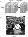
- the inventors assembled a dosimetry phantom by sandwiching GAFCHROMIC EBT2 films (International Specialty Products, Wayne, NJ) between slabs of tissue equivalent polystyrene as shown in Figure 3 .
- Figure 3a is a schematic and Figure 3b is a photograph of the experimental setup for film measurements ( Figure 3c ) of very high- energy electron beams at the NLCTA beam line at SLAC.
- Monte Carlo simulations and film measurements of percentage depth dose curves ( Figure 3d ) and 2-D dose distributions taken at 6 mm depth ( Figure 3e ) for 50 MeV and 70 MeV beams demonstrate a high degree of agreement between calculation and measurement.
- the phantom as shown in Figure 3a was irradiated with 50 MeV and 70 MeV beams. Three beam sizes ranging from 3.35 to 6.15 mm were tested for each energy level. The energy was measured by a spectrometer upstream from the location of the experiment and the beam size was measured by two scintillating screens using two cameras just before and after the phantom with the phantom removed from the beam line ( Figure 3b ). The films were calibrated with a clinical electron beam at 12 MeV. MC simulations have demonstrated no energy dependence of the film response at electron energies above 1 MeV.
- the number of particles required to irradiate the films to dose levels between 1-5 Gy to match the dynamic range of the film was determined for each beam size using MC simulations and used in the experiment.
- the charge was set to 30 pC/pulse corresponding to 1.9x10 8 electrons and the pulse rate was reduced to 1 Hz for easier control of the exposure.
- the number of pulses varied from 2 to 40 pulses depending on the beam size.
- the experimental and calibration films were read out in a flatbed scanner (Epson Perfection V500, Long Beach, CA) with 0.1 mm pixels 24 hours after irradiation ( Figure 3c ) and central axis percentage depth dose (PDD) curves and 2-dimensional dose distributions at various depths were plotted.
- a 50- ⁇ m vacuum window made of stainless steel was used to interface the accelerator line with open air, in which the dose phantom ( Figure 2a ) was placed.
- the stainless window was found to cause significant angular beam spreading, so that the simulations were also performed with a beryllium window which imparted less beam spreading. While a vacuum window is necessary to separate the vacuum of the accelerator beam line from the open air and the patient, significant angular spread will adversely affect beam performance and clinical accuracy.
- the angular spread from a thinner beryllium window was still present but it was much smaller than steel, due to beryllium's low atomic number.
- the inventors performed Monte Carlo simulations using three independent codes for identical geometries to determine the consistency of calculated doses.
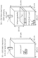
- the dose deposition of a number of rectangular electron beams incident on a 20 ⁇ 20 ⁇ 30 cm water phantom (as shown in Figure 7a ) was simulated in the GEANT4, MCNPX, and EGSnrc MC codes.
- the simulated electron beam energies were 50, 75, 100, and 150 MeV with beam sizes of 1 ⁇ 1 cm and 2 ⁇ 2 cm.
- the central-axis PDDs were plotted and compared for all three MC codes. Excellent agreement was found between the codes for all of these comparisons, as shown in Figure 4 , which shows PDD for a 2x2 cm 100 MeV electron beam, simulated using the three Monte Carlo codes.
- FIG. 5 shows PDD curves for 2 ⁇ 2 cm 50 and 150 MeV electron beams compared to 6MV photons in a water phantom with 2 cm thick heterogeneous tissue at 10 cm depth, normalized to identical dose at 3 cm depth.
- the 50 and 150 MeV VHEE beams are less sensitive to tissue heterogeneity over the density range from lung tissue to titanium prosthetic implants compared to 6 MV photons.
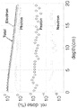
- Figure 6 shows relative contribution to dose from a 100 MeV electron beam vs. secondary generated particles (log scale). As shown in Figure 6 , for a 100 MeV electron beam, nearly all the deposited dose is due to electrons, with a minor contribution from Bremsstrahlung x-rays, and far lower dose from protons and neutrons. Figure 6 also shows that dose from neutrons is far less than with 15-18 MV photons or high-energy protons. This holds for 50 and 70 MeV electrons as well (not shown).
- an upper limit of total body neutron dose is estimated to be 0.6 mSv based on MC simulations. This is in contrast to more than 1-2 orders of magnitude greater estimated neutron doses of 9-170 mSv for scanning beam proton therapy and 15-18 MV photon IMRT for the same clinical scenario, based on published measurements of ambient neutron doses [ Schneider U, Agosteo S, Pedroni E, and Besserer J., "Secondary neutron dose during proton therapy using spot scanning," International Journal of Radiation Oncology Biology Physics, 2002; 53(1): 244-251 .
- tissue inhomogeneities on dose deposition of VHEE beams has been studied by the inventors.
- a 20x20x25 cm3 water phantom with 0.5x0.5x0.1 cm3 voxels and a 2-cm thick inhomogeneity placed at 10 cm depth was built ( Figure 7b ).
- the tissue composition was obtained from the ICRU-44 document [ICRU.
- Pluridirectional very high electron energy radiation therapy systems and processes according to various embodiments of the disclsoure can be created with various types of electron source.
- a non- exhaustive list includes cyclotrons, synchrotrons, linacs (which can include more conventional designs with greater length), racetrack microtrons, dielectric wall accelerators, and laser plasma wakefield accelerator sources. Some of these are large and would need to be housed in a separate room. Some are not very mature technologies.
- compact very high-gradient standing wave linear accelerators such as those developed at SLAC as described in the two paragraphs immediately below, or derivatives of them, may be at least a logical starting point, although other currently existing or future options should not be ruled out.
- optimized designs according to certain embodiments of the disclsosure allow both economical production and high performance to minimize the treatment time while allowing maximum possible flexibility in beamlet shapes, directionality, and energy.
- RF source requirements depend ultimately, at least in part, on the accelerator design. With the optimized cavities as described above, it is projected that a 50 MW source at X-band will be sufficient for a 2 meter accelerator operating at 50 MV/m. This type of source is available at SLAC and is being commercialized by Communications & Power Industries (Palo Alto, CA). With the use of a pulse compression system it may be possible to either reduce the cost and sophistication of the RF source dramatically or make the accelerator structure more compact by reducing the length to 1 meter.
- the typical filling time of such a structure is about 100 ns and the RF source typically provides several ⁇ s long pulses
- a compact pulse compressor with a high compression ratio and a power gain of about 3.5 to reduce the required RF source power to only about 14 MW, which opens the door for a variety of sources, including sources that are commercially available now, and including those that include a pulse compression system.
- treatment according to certain embodiments of the disclosure is delivered sufficiently fast to freeze physiologic motion, it is important to verify that the target is in the planned position at the time the treatment is triggered or administered.
- Several dynamic or "real-time" imaging or other localization technologies can be integrated into certain embodiments of the disclosure for this purpose. Potential such implementations can include any of the following, alone or in combination:
- dynamic visualization and/or automated image analysis tools can be used to permit either manual triggering of the treatment by the operator, or automated triggering with manual override.
- radiation fields from each of multiple beam directions can cover an area with varying beam intensity across the field, with the intensity patterns optimized to produce the desired 3-dimensional dose distribution when summed across all beam directions.
- intensity modulation may be produced by raster scanning individual beamlets of varying intensity across the field from each beam direction.
- it may be produced by using a 2- dimensional intensity-modulated electron pattern at the source, effectively an array of beamlets of varying intensity, and accelerate and steer the entire array to the target volume.
- the intensity modulation of the electron source may be produced by using a photocathode illuminated by a light source with the corresponding intensity pattern, in effect, an optical image.
- a photocathode illuminated by a light source with the corresponding intensity pattern in effect, an optical image.
- One implementation is to use a laser as the light source, and a digital light processing (DLP) micromirror array or other intensity modulating device to produce the charge image on the photocathode to be accelerated and steered.
- DLP digital light processing
- the electron beam optics can be designed to maintain the pattern with high fidelity until it reaches the target.
- a short, typically picosecond-long pulse with uniform transverse profile is generated by a laser (1).
- the wavelength of the laser is matched with specific photocathode material to obtain required charge and emittance.
- the laser pulse (2) falls on a digital-micro- mirror device (3). Pixels of this micro-mirror device are controlled by a computer and will reflect a portion of the laser pulse (4) thus creating an image that is then transferred to the photocathode (6) using precision projection optics (5).
- various types of accelerators may be used with this embodiment, high gradient pulsed devices with a few milliseconds between pulses are preferable.
- the computer modulates the mirror array thus creating a new image for each consequent pulse.
- a laser pulse with amplitude-modulated transverse profile that impacts the photocathode (6) will create an electron replica of the laser pulse transverse profile (8).
- the photocathode (6) is a part of photo-electron gun (7).
- the gun creates an electric field on the photocathode which accelerates the transverse-modulated electron beam.
- the gun also provides initial focusing for the electron beam.
- the electron beam then passes through the low-aberration focusing system toward accelerator (10).
- the accelerator increases energy of the beam to a desired value.
- the electron beam then passes through focusing optics (11) toward horizontal (12) and vertical (13) fast deflectors.
- the deflectors are controlled by a computer and are able to send the electron beam in different directions for each consecutive accelerator pulse.
- the desired direction will depend on (among other things) specific realization of the gantry's beam lines, number of the beam lines and whether they are movable or not. For clarity only one gantry beam line is shown in Figure 8 .
- the electron beam passes through bending magnets (14, 16, 18) and electron optics (15, 17) and is directed through electron-beam monitoring system (19) toward the target (20).
- the transversely modulated electron beam irradiates the target with required distribution of the dose.
- the beam is sent toward beam dump (21) in order to reduce unwanted radiation exposure of the target.
Landscapes
- Health & Medical Sciences (AREA)
- Engineering & Computer Science (AREA)
- Biomedical Technology (AREA)
- Pathology (AREA)
- Nuclear Medicine, Radiotherapy & Molecular Imaging (AREA)
- Radiology & Medical Imaging (AREA)
- Life Sciences & Earth Sciences (AREA)
- Animal Behavior & Ethology (AREA)
- General Health & Medical Sciences (AREA)
- Public Health (AREA)
- Veterinary Medicine (AREA)
- Radiation-Therapy Devices (AREA)
Claims (15)
- Système conçu pour délivrer des faisceaux d'électrons de très haute énergie (8) à un tissu ciblé (20) chez un patient, le système comprenant :un ou plusieurs accélérateurs (10) configurés pour générer un ou plusieurs faisceaux d'électrons de très haute énergie (8) ayant une énergie de 50 à 250 MeV ;un ou plusieurs dispositifs d'orientation de faisceau configurés pour recevoir lesdits un ou plusieurs faisceaux d'électrons de très haute énergie (8) provenant desdits un ou plusieurs accélérateurs (10) et orienter lesdits un ou plusieurs faisceaux d'électrons de très haute énergie (8) vers le tissu ciblé (20) à partir de multiples directions sans nécessiter de mouvement de pièces mécaniques quelconques ; etun contrôleur capable de contrôler une durée d'irradiation du tissu ciblé (20) par lesdits un ou plusieurs faisceaux d'électrons de très haute énergie (8) de telle sorte qu'elle soit inférieure à 10 secondes.
- Système selon la revendication 1, dans lequel le contrôleur est configuré pour recevoir des informations provenant d'un dispositif d'imagerie ou d'un dispositif de ciblage et utiliser les informations provenant du dispositif pour contrôler les directions dans lesquelles le dispositif d'orientation de faisceau oriente lesdits un ou plusieurs faisceaux d'électrons de très haute énergie (8) vers le tissu ciblé (20), dans lequel la délivrance au tissu ciblé (20) par le dispositif d'orientation de faisceau est basée sur des données de vérification de position reçues en provenance du dispositif d'imagerie ou de ciblage.
- Système selon la revendication 1, dans lequel lesdits un ou plusieurs accélérateurs (10) sont capables de générer un faisceau de 1 à 250 MeV.
- Système selon la revendication 1, dans lequel la durée de la délivrance est inférieure à une seconde.
- Système selon la revendication 1, dans lequel le dispositif d'orientation de faisceau présente au moins l'une des caractéristiques suivantes :est sélectionné dans le groupe constitué de dispositifs électromagnétiques et de dispositifs de déviation à radiofréquence ;comprend un portique, le portique comprenant de multiples orifices de passage de faisceau ;est capable de produire un balayage tramé avec un faisceau très mince ;comprend un portique annulaire continu ;est capable de produire un balayage pour le remplissage de volumes.
- Système selon l'une quelconque des revendications 1, 3, 4 ou 5, comprenant :
un dispositif d'imagerie capable de générer des images du tissu ciblé (20) et de fournir des informations provenant du dispositif d'imagerie au contrôleur pour contrôler les directions dans lesquelles le dispositif d'orientation de faisceau oriente le faisceau vers le tissu ciblé (20). - Système selon la revendication 6, dans lequel le dispositif d'imagerie est capable de fournir des informations au contrôleur pour déclencher le moment de la délivrance du faisceau au tissu ciblé (20) par le système.
- Système selon la revendication 6, dans lequel, en utilisant des informations provenant du dispositif d'imagerie, le système est capable de délivrer automatiquement le faisceau au tissu ciblé (20) à partir de multiples directions prédéterminées à de multiples points temporels prédéterminés.
- Système selon la revendication 1, comprenant en outre : un dispositif d'imagerie qui est capable de fournir des informations au contrôleur pour déclencher le moment de la délivrance du faisceau au tissu ciblé (20) par le système ; ou
un dispositif d'imagerie configuré pour fournir des informations dont l'utilisation rend le système capable de délivrer automatiquement le faisceau au tissu ciblé (20) à partir de multiples directions prédéterminées à de multiples points temporels prédéterminés. - Système selon la revendication 1, conçu pour délivrer un faisceau d'électrons à modulation transversale à un tissu ciblé (20) chez un patient, comprenant :un canon photoélectronique configuré pour générer un faisceau d'électrons à modulation transversale à partir d'une image optique produite par une source lumineuse et projetée sur une photocathode ;dans lequel l'accélérateur (10) est capable d'augmenter le niveau d'énergie du faisceau d'électrons à modulation transversale jusqu'à un niveau prédéterminé ;le dispositif d'orientation de faisceau est capable de recevoir le faisceau d'électrons à modulation transversale provenant de l'accélérateur (10) et d'orienter le faisceau d'électrons à modulation transversale vers le tissu ciblé (20) à partir de multiples orientations ; etle contrôleur est capable de contrôler une durée d'irradiation du tissu ciblé (20) par le faisceau d'électrons à modulation transversale de telle sorte qu'elle soit inférieure à 10 secondes, et de contrôler les directions dans lesquelles le dispositif d'orientation de faisceau oriente le faisceau d'électrons à modulation transversale vers le tissu ciblé (20) durant la délivrance.
- Système de délivrance d'un faisceau d'électrons à modulation transversale à un tissu ciblé (20) chez un patient selon la revendication 10, dans lequel la source lumineuse est un laser (1).
- Système selon la revendication 1, dans lequel lesdits un ou plusieurs faisceaux de particules reçus en provenance desdits un ou plusieurs accélérateurs (10) sont amenés par l'intermédiaire d'un ou plusieurs canaux à un ou plusieurs orifices de sortie avant la délivrance au tissu ciblé (20), dans lequel chacun desdits un ou plusieurs faisceaux sort de l'orifice de sortie respectif à un angle de sortie associé de telle sorte que lesdits un ou plusieurs faisceaux soient dirigés vers le tissu ciblé (20) à partir de multiples directions dans une gamme d'orientations non planes.
- Système selon la revendication 2, dans lequel le système d'imagerie ou de ciblage est configuré pour obtenir une image du tissu ciblé (20) et/ou d'un emplacement ciblé du tissu ciblé (20) immédiatement avant la délivrance du faisceau de particules.
- Système selon la revendication 12, dans lequel le contrôleur est configuré pour contrôler la délivrance du faisceau au tissu ciblé (20) sur la base d'une comparaison entre l'image et une image de planification antérieure au traitement.
- Système selon l'une quelconque des revendications précédentes, comprenant en outre (i) un ensemble de cibles à haute densité et une grille de collimation ou (ii) une cible à haute densité montée sur un anneau fermé à rotation rapide dans un orifice de passage de faisceau annulaire, afin de produire, à partir desdits un ou plusieurs faisceaux d'électrons de très haute énergie, des faisceaux de photons multidirectionnels à balayage rapide qui sont dirigés vers le tissu ciblé (20).
Applications Claiming Priority (2)
| Application Number | Priority Date | Filing Date | Title |
|---|---|---|---|
| US201261606408P | 2012-03-03 | 2012-03-03 | |
| PCT/US2013/025765 WO2013133936A1 (fr) | 2012-03-03 | 2013-02-12 | Systèmes et processus de radiothérapie pluridirectionnelle à très haute énergie d'électrons |
Publications (3)
| Publication Number | Publication Date |
|---|---|
| EP2823501A1 EP2823501A1 (fr) | 2015-01-14 |
| EP2823501A4 EP2823501A4 (fr) | 2015-10-21 |
| EP2823501B1 true EP2823501B1 (fr) | 2019-05-01 |
Family
ID=49043206
Family Applications (1)
| Application Number | Title | Priority Date | Filing Date |
|---|---|---|---|
| EP13757604.7A Active EP2823501B1 (fr) | 2012-03-03 | 2013-02-12 | Systèmes de radiothérapie pluridirectionnelle à très haute énergie d'électrons |
Country Status (4)
| Country | Link |
|---|---|
| US (2) | US8618521B2 (fr) |
| EP (1) | EP2823501B1 (fr) |
| CN (1) | CN104246961B (fr) |
| WO (1) | WO2013133936A1 (fr) |
Cited By (2)
| Publication number | Priority date | Publication date | Assignee | Title |
|---|---|---|---|---|
| US12569700B2 (en) | 2017-07-21 | 2026-03-10 | Varian Medical Systems, Inc. | Methods of use of ultra-high dose rate radiation and therapeutic agent |
| USRE50811E1 (en) | 2013-09-11 | 2026-03-10 | The Board Of Trustees Of The Leland Stanford Junior University | Rapid imaging systems and methods for facilitating rapid radiation therapies |
Families Citing this family (58)
| Publication number | Priority date | Publication date | Assignee | Title |
|---|---|---|---|---|
| JP5391229B2 (ja) * | 2011-04-27 | 2014-01-15 | 富士フイルム株式会社 | 木構造抽出装置および方法ならびにプログラム |
| US8787529B2 (en) * | 2011-05-11 | 2014-07-22 | Massachusetts Institute Of Technology | Compact coherent current and radiation source |
| EP2823501B1 (fr) * | 2012-03-03 | 2019-05-01 | The Board of Trustees of The Leland Stanford Junior University | Systèmes de radiothérapie pluridirectionnelle à très haute énergie d'électrons |
| US20130304409A1 (en) * | 2012-05-10 | 2013-11-14 | Board Of Regents, The University Of Texas System | Methods for validating plastic scintillating detectors and applications of same |
| JP5917322B2 (ja) * | 2012-07-12 | 2016-05-11 | 住友重機械工業株式会社 | 荷電粒子線照射装置 |
| US20150065777A1 (en) * | 2013-08-29 | 2015-03-05 | Naser Darwish | Radiation therapy machine with real-time ebt imaging |
| WO2015102681A2 (fr) * | 2013-09-11 | 2015-07-09 | The Board Of Trustees Of The Leland Stanford Junior University | Procédés et systèmes de génération et de distribution de puissance rf pour faciliter des radiothérapies rapides |
| US9962560B2 (en) | 2013-12-20 | 2018-05-08 | Mevion Medical Systems, Inc. | Collimator and energy degrader |
| US10675487B2 (en) | 2013-12-20 | 2020-06-09 | Mevion Medical Systems, Inc. | Energy degrader enabling high-speed energy switching |
| CN104001270B (zh) * | 2014-05-07 | 2016-07-06 | 上海交通大学 | 超高能电子束或光子束放射治疗机器人系统 |
| US9950194B2 (en) | 2014-09-09 | 2018-04-24 | Mevion Medical Systems, Inc. | Patient positioning system |
| US10252083B2 (en) | 2015-09-23 | 2019-04-09 | Varian Medical Systems Inc. | Systems, methods, and devices for high-energy irradiation |
| US10786689B2 (en) | 2015-11-10 | 2020-09-29 | Mevion Medical Systems, Inc. | Adaptive aperture |
| US9812282B2 (en) * | 2015-11-26 | 2017-11-07 | Mevex Corporation | System and method for irradiating a product |
| WO2017132341A1 (fr) * | 2016-01-26 | 2017-08-03 | The Board Of Regents Of The University Of Texas System | Techniques de ponction à portée de plan médian pour thérapie par particules |
| US9855445B2 (en) * | 2016-04-01 | 2018-01-02 | Varian Medical Systems, Inc. | Radiation therapy systems and methods for delivering doses to a target volume |
| US10925147B2 (en) | 2016-07-08 | 2021-02-16 | Mevion Medical Systems, Inc. | Treatment planning |
| US10974076B2 (en) | 2016-12-14 | 2021-04-13 | Varian Medical Systems, Inc | Dynamic three-dimensional beam modification for radiation therapy |
| US10170228B2 (en) | 2017-01-11 | 2019-01-01 | National Synchrotron Radiation Research Center | Magnetic apparatus |
| US11103730B2 (en) | 2017-02-23 | 2021-08-31 | Mevion Medical Systems, Inc. | Automated treatment in particle therapy |
| IL269721B2 (en) | 2017-03-31 | 2024-07-01 | Sensus Healthcare Inc | A three-dimensional beam that creates an x-ray radiation source |
| US10661102B2 (en) * | 2017-03-31 | 2020-05-26 | Varian Medical Systems, Inc. | Treatment energy delivery system |
| US10300304B2 (en) * | 2017-04-05 | 2019-05-28 | Pyramid Technical Consultants Inc. | Safety dose interlock for charged particle beams |
| WO2018222839A1 (fr) | 2017-06-01 | 2018-12-06 | Radiabeam Technologies, Llc | Accélérateurs de particules à structure divisée |
| JP6940676B2 (ja) | 2017-06-30 | 2021-09-29 | メビオン・メディカル・システムズ・インコーポレーテッド | リニアモーターを使用して制御される構成可能コリメータ |
| KR20200072463A (ko) | 2017-07-18 | 2020-06-22 | 센서스 헬스케어 인코포레이티드 | 수술중 방사선 치료에서의 실시간 x선 선량 측정 |
| US11712579B2 (en) | 2017-07-21 | 2023-08-01 | Varian Medical Systems, Inc. | Range compensators for radiation therapy |
| US10183179B1 (en) | 2017-07-21 | 2019-01-22 | Varian Medical Systems, Inc. | Triggered treatment systems and methods |
| US10609806B2 (en) | 2017-07-21 | 2020-03-31 | Varian Medical Systems Particle Therapy Gmbh | Energy modulation of a cyclotron beam |
| US10245448B2 (en) | 2017-07-21 | 2019-04-02 | Varian Medical Systems Particle Therapy Gmbh | Particle beam monitoring systems and methods |
| US10092774B1 (en) | 2017-07-21 | 2018-10-09 | Varian Medical Systems International, AG | Dose aspects of radiation therapy planning and treatment |
| US10549117B2 (en) | 2017-07-21 | 2020-02-04 | Varian Medical Systems, Inc | Geometric aspects of radiation therapy planning and treatment |
| US11590364B2 (en) | 2017-07-21 | 2023-02-28 | Varian Medical Systems International Ag | Material inserts for radiation therapy |
| US10843011B2 (en) | 2017-07-21 | 2020-11-24 | Varian Medical Systems, Inc. | Particle beam gun control systems and methods |
| EP3710111B1 (fr) | 2017-11-16 | 2021-12-29 | Varian Medical Systems, Inc. | Sortie de faisceau améliorée et mise en forme de champ dynamique destinés à un système de radiothérapie |
| US11672491B2 (en) | 2018-03-30 | 2023-06-13 | Empyrean Medical Systems, Inc. | Validation of therapeutic radiation treatment |
| US10910188B2 (en) | 2018-07-25 | 2021-02-02 | Varian Medical Systems, Inc. | Radiation anode target systems and methods |
| US11612049B2 (en) | 2018-09-21 | 2023-03-21 | Radiabeam Technologies, Llc | Modified split structure particle accelerators |
| US10940334B2 (en) * | 2018-10-19 | 2021-03-09 | Sensus Healthcare, Inc. | Systems and methods for real time beam sculpting intra-operative-radiation-therapy treatment planning |
| CN109613597B (zh) | 2018-11-30 | 2021-04-06 | 上海联影医疗科技股份有限公司 | 一种确定电子束能谱的方法及系统 |
| KR102174488B1 (ko) * | 2018-11-30 | 2020-11-05 | (주)아우라케어 | 방사선 촬영 및 치료 장치 |
| US10814144B2 (en) | 2019-03-06 | 2020-10-27 | Varian Medical Systems, Inc. | Radiation treatment based on dose rate |
| US11116995B2 (en) | 2019-03-06 | 2021-09-14 | Varian Medical Systems, Inc. | Radiation treatment planning based on dose rate |
| US11103727B2 (en) | 2019-03-08 | 2021-08-31 | Varian Medical Systems International Ag | Model based PBS optimization for flash therapy treatment planning and oncology information system |
| US11090508B2 (en) | 2019-03-08 | 2021-08-17 | Varian Medical Systems Particle Therapy Gmbh & Co. Kg | System and method for biological treatment planning and decision support |
| US10918886B2 (en) | 2019-06-10 | 2021-02-16 | Varian Medical Systems, Inc. | Flash therapy treatment planning and oncology information system having dose rate prescription and dose rate mapping |
| WO2021061666A1 (fr) | 2019-09-25 | 2021-04-01 | Reflexion Medical, Inc. | Systèmes et méthodes de radiothérapie à dose flash |
| US11291859B2 (en) | 2019-10-03 | 2022-04-05 | Varian Medical Systems, Inc. | Radiation treatment planning for delivering high dose rates to spots in a target |
| US12390662B2 (en) | 2020-04-02 | 2025-08-19 | Siemens Healthineers International Ag | System and method for proton therapy treatment planning with proton energy and spot optimization |
| US11865361B2 (en) | 2020-04-03 | 2024-01-09 | Varian Medical Systems, Inc. | System and method for scanning pattern optimization for flash therapy treatment planning |
| US11541252B2 (en) | 2020-06-23 | 2023-01-03 | Varian Medical Systems, Inc. | Defining dose rate for pencil beam scanning |
| EP3928833A1 (fr) * | 2020-06-24 | 2021-12-29 | Centre Hospitalier Universitaire Vaudois (CHUV) | Dispositif pour fournir un traitement par rayonnement |
| US11957934B2 (en) | 2020-07-01 | 2024-04-16 | Siemens Healthineers International Ag | Methods and systems using modeling of crystalline materials for spot placement for radiation therapy |
| US12064645B2 (en) | 2020-07-02 | 2024-08-20 | Siemens Healthineers International Ag | Methods and systems used for planning radiation treatment |
| US20220304136A1 (en) * | 2021-03-17 | 2022-09-22 | Varian Medical Systems, Inc. | Use of magnetic elements to shape and defocus charged particle beams |
| CN113908452B (zh) * | 2021-10-15 | 2024-05-24 | 国宏国康(北京)健康科技发展有限公司 | 一种质子治疗辅助定位光照系统及方法 |
| CN114668986B (zh) * | 2022-03-31 | 2025-09-12 | 上海联影医疗科技股份有限公司 | 一种放射治疗装置、光子闪疗系统及超高能电子闪疗系统 |
| CN119280706A (zh) * | 2024-08-29 | 2025-01-10 | 苏州宜瑞新速医疗科技有限公司 | 医用直线加速器的辐射系统及其方法 |
Citations (1)
| Publication number | Priority date | Publication date | Assignee | Title |
|---|---|---|---|---|
| US20100207042A1 (en) * | 2008-06-09 | 2010-08-19 | Mitsubishi Electric Corporation | Particle beam treatment apparatus and respiration navigation apparatus used therefor |
Family Cites Families (45)
| Publication number | Priority date | Publication date | Assignee | Title |
|---|---|---|---|---|
| US3757118A (en) | 1972-02-22 | 1973-09-04 | Ca Atomic Energy Ltd | Electron beam therapy unit |
| US4644168A (en) | 1984-05-14 | 1987-02-17 | Imatron Inc. | Electron beam deflecting magnet assembly for a scanning electron beam computed tomography scanner |
| US4726046A (en) | 1985-11-05 | 1988-02-16 | Varian Associates, Inc. | X-ray and electron radiotherapy clinical treatment machine |
| US4737647A (en) | 1986-03-31 | 1988-04-12 | Siemens Medical Laboratories, Inc. | Target assembly for an electron linear accelerator |
| US5452720A (en) * | 1990-09-05 | 1995-09-26 | Photoelectron Corporation | Method for treating brain tumors |
| US5684854A (en) * | 1996-08-12 | 1997-11-04 | Siemens Medical System Inc | Method and system for dynamically establishing field size coincidence |
| US6333966B1 (en) | 1998-08-18 | 2001-12-25 | Neil Charles Schoen | Laser accelerator femtosecond X-ray source |
| US6332017B1 (en) | 1999-01-25 | 2001-12-18 | Vanderbilt University | System and method for producing pulsed monochromatic X-rays |
| US6537052B1 (en) | 1999-08-23 | 2003-03-25 | Richard J. Adler | Method and apparatus for high speed electron beam rapid prototyping |
| JP3736343B2 (ja) | 2000-03-09 | 2006-01-18 | 三菱電機株式会社 | 直流電子ビーム加速装置およびその直流電子ビーム加速方法 |
| WO2001076021A2 (fr) * | 2000-03-31 | 2001-10-11 | University Of Maryland, Baltimore | Dispositif de production de faisceaux electroniques de forme helicoidale et procede d'utilisation |
| DE10041473B9 (de) | 2000-08-24 | 2004-10-14 | Müller, Reinhold G., Prof.Dr. | Vorrichtung zur Bestrahlung von Gewebe |
| AU2001294604A1 (en) | 2000-09-22 | 2002-04-02 | Numerix Llc | Improved radiation therapy treatment method |
| US6459762B1 (en) | 2001-03-13 | 2002-10-01 | Ro Inventions I, Llc | Method for producing a range of therapeutic radiation energy levels |
| US20020191746A1 (en) | 2001-06-19 | 2002-12-19 | Mark Dinsmore | X-ray source for materials analysis systems |
| CA2427541C (fr) * | 2001-08-24 | 2013-04-16 | Mitsubishi Heavy Industries, Ltd. | Appareil de radiotherapie |
| US6724782B2 (en) | 2002-04-30 | 2004-04-20 | The Regents Of The University Of California | Femtosecond laser-electron x-ray source |
| EP1358908A1 (fr) * | 2002-05-03 | 2003-11-05 | Ion Beam Applications S.A. | Appareil de radiothérapie à particules chargées |
| US20040082855A1 (en) | 2002-07-19 | 2004-04-29 | Bc Cancer Agency | Tumor dose enhancement using modified photon beams and contrast media |
| US7015467B2 (en) * | 2002-10-10 | 2006-03-21 | Applied Materials, Inc. | Generating electrons with an activated photocathode |
| JP4356019B2 (ja) | 2002-10-25 | 2009-11-04 | 独立行政法人科学技術振興機構 | 電子加速器及びそれを用いた放射線治療装置 |
| FR2857555B1 (fr) | 2003-07-09 | 2005-10-14 | Snecma Moteurs | Accelerateur a plasma a derive fermee d'electrons |
| US7206379B2 (en) | 2003-11-25 | 2007-04-17 | General Electric Company | RF accelerator for imaging applications |
| WO2006104956A2 (fr) | 2005-03-25 | 2006-10-05 | Massachusetts Institute Of Technology | Source compacte de rayons x a impulsions courtes et a flux eleve |
| EP1745821A1 (fr) | 2005-07-20 | 2007-01-24 | Ecole Polytechnique | Dispositif et procédé pour la création d'une répartition de dose spatielle dans un volume de médium |
| EP1906827A4 (fr) | 2005-07-22 | 2009-10-21 | Tomotherapy Inc | Systeme et methode pour evaluer une dose administree par un systeme de radiotherapie |
| CN101453951A (zh) * | 2006-05-25 | 2009-06-10 | 皇家飞利浦电子股份有限公司 | 锥束ct半周期闭合螺旋轨迹 |
| DE102007019355A1 (de) | 2006-06-26 | 2008-01-03 | Forster, Jan | Vorrichtung zur Bestrahlung von Gewebe mit mindestens einer Elektronenquelle sowie mit einer Mehrzahl von Strahlerköpfen |
| ATE511888T1 (de) * | 2007-02-27 | 2011-06-15 | Wisconsin Alumni Res Found | Strahlentherapiesystem mit schweren ionen mit stairstep-modulation |
| US7630474B2 (en) | 2007-09-28 | 2009-12-08 | Varian Medical Systems, Inc. | Radiation scanning with photon tagging |
| US8467497B2 (en) * | 2007-10-25 | 2013-06-18 | Tomotherapy Incorporated | System and method for motion adaptive optimization for radiation therapy delivery |
| WO2009064715A1 (fr) * | 2007-11-14 | 2009-05-22 | Auckland Uniservices Limited | Procédé de maillage multi-échelle de structures biologiques d'arborisation |
| US7835492B1 (en) * | 2007-11-27 | 2010-11-16 | Velayudhan Sahadevan | Lethal and sublethal damage repair inhibiting image guided simultaneous all field divergent and pencil beam photon and electron radiation therapy and radiosurgery |
| US7741624B1 (en) | 2008-05-03 | 2010-06-22 | Velayudhan Sahadevan | Single session interactive ultra-short duration super-high biological dose rate radiation therapy and radiosurgery |
| US8350226B2 (en) | 2008-10-23 | 2013-01-08 | Varian Medical Systems, Inc. | Methods and systems for treating cancer using external beam radiation |
| US8232748B2 (en) | 2009-01-26 | 2012-07-31 | Accuray, Inc. | Traveling wave linear accelerator comprising a frequency controller for interleaved multi-energy operation |
| EP2403600A4 (fr) | 2009-03-03 | 2012-08-29 | Tomotherapy Inc | Système et procédé d'optimisation d'une dose de rayonnement hétérogène devant être administrée à un patient |
| JP4418888B1 (ja) | 2009-03-25 | 2010-02-24 | 株式会社アキュセラ | X線治療装置 |
| US8027431B2 (en) | 2009-06-23 | 2011-09-27 | Siemens Medical Solutions Usa, Inc. | System and method for dynamic strobe arc therapy |
| DE102009028362A1 (de) | 2009-08-07 | 2011-02-10 | Stefan Trummer | Strahllagemonitor für Elektronen-Linearbeschleuniger |
| JP5133319B2 (ja) * | 2009-09-30 | 2013-01-30 | 株式会社日立製作所 | 粒子線照射システムおよびその制御方法 |
| US8315357B2 (en) | 2009-10-08 | 2012-11-20 | The Board Of Trustees Of The Leland Stanford Junior University | Radiation therapy inverse treatment planning using a regularization of sparse segments |
| US8803453B2 (en) | 2011-06-22 | 2014-08-12 | Varian Medical Systems, Inc. | Accelerator system stabilization for charged particle acceleration and radiation beam generation |
| US8405044B2 (en) | 2011-07-15 | 2013-03-26 | Accuray Incorporated | Achromatically bending a beam of charged particles by about ninety degrees |
| EP2823501B1 (fr) * | 2012-03-03 | 2019-05-01 | The Board of Trustees of The Leland Stanford Junior University | Systèmes de radiothérapie pluridirectionnelle à très haute énergie d'électrons |
-
2013
- 2013-02-12 EP EP13757604.7A patent/EP2823501B1/fr active Active
- 2013-02-12 CN CN201380021479.0A patent/CN104246961B/zh active Active
- 2013-02-12 WO PCT/US2013/025765 patent/WO2013133936A1/fr not_active Ceased
- 2013-02-12 US US13/765,017 patent/US8618521B2/en active Active
- 2013-11-01 US US14/070,376 patent/US9018603B2/en active Active
Patent Citations (1)
| Publication number | Priority date | Publication date | Assignee | Title |
|---|---|---|---|---|
| US20100207042A1 (en) * | 2008-06-09 | 2010-08-19 | Mitsubishi Electric Corporation | Particle beam treatment apparatus and respiration navigation apparatus used therefor |
Non-Patent Citations (1)
| Title |
|---|
| FURUKAWA TAKUJI ET AL: "Design study of a raster scanning system for moving target irradiation in heavy-ion radiotherapy", MEDICAL PHYSICS, AIP, MELVILLE, NY, US, vol. 34, no. 3, 27 February 2007 (2007-02-27), pages 1085 - 1097, XP012103329, ISSN: 0094-2405, DOI: 10.1118/1.2558213 * |
Cited By (2)
| Publication number | Priority date | Publication date | Assignee | Title |
|---|---|---|---|---|
| USRE50811E1 (en) | 2013-09-11 | 2026-03-10 | The Board Of Trustees Of The Leland Stanford Junior University | Rapid imaging systems and methods for facilitating rapid radiation therapies |
| US12569700B2 (en) | 2017-07-21 | 2026-03-10 | Varian Medical Systems, Inc. | Methods of use of ultra-high dose rate radiation and therapeutic agent |
Also Published As
| Publication number | Publication date |
|---|---|
| CN104246961A (zh) | 2014-12-24 |
| US9018603B2 (en) | 2015-04-28 |
| US8618521B2 (en) | 2013-12-31 |
| WO2013133936A1 (fr) | 2013-09-12 |
| CN104246961B (zh) | 2017-05-17 |
| EP2823501A4 (fr) | 2015-10-21 |
| US20130231516A1 (en) | 2013-09-05 |
| EP2823501A1 (fr) | 2015-01-14 |
| US20140135563A1 (en) | 2014-05-15 |
Similar Documents
| Publication | Publication Date | Title |
|---|---|---|
| USRE50811E1 (en) | Rapid imaging systems and methods for facilitating rapid radiation therapies | |
| EP2823501B1 (fr) | Systèmes de radiothérapie pluridirectionnelle à très haute énergie d'électrons | |
| US10485991B2 (en) | Methods and systems for RF power generation and distribution to facilitate rapid radiation therapies | |
| US20100006106A1 (en) | Semi-vertical positioning method and apparatus used in conjunction with a charged particle cancer therapy system | |
| US20080234531A1 (en) | Bi-polar treatment facility for treating target cells with both positive and negative ions | |
| Flanz et al. | Evolution of technology to optimize the delivery of proton therapy: the third generation | |
| WO2023205395A1 (fr) | Dispositif d'irradiation de radiothérapie flash pour petits animaux et micro-tdm à géométrie inverse | |
| Schneider | Advancing the generation of proton minibeams for radiation therapy | |
| Vanstalle et al. | Investigation of optimal physical parameters for precise proton irradiation of orthotopic tumors in small animals | |
| Maciszewski et al. | Particle accelerators for radiotherapy. Present status and future | |
| Shende et al. | Physics in treatment of cancer radiotherapy | |
| CN114761078A (zh) | 在受试者的强子疗法治疗期间监测强子束的方法和系统 | |
| Yoshida et al. | Electron accelerator and beam irradiation system | |
| US20250352826A1 (en) | Installation of proton therapy equipment in existing radiotherapy treatment vaults | |
| Whitmore | Very High Energy Electron (VHEE) Radiotherapy: Focused Dose Delivery and Image Guidance | |
| Flinton | Radiotherapy Beam Production | |
| Pryanichnikov et al. | Dual-energy extraction for proton therapy and imaging: validation on a clinical synchrotron-based facility | |
| Wysocka-Rabin | Advances in conformal radiotherapy: using Monte Carlo Code to design new IMRT and IORT accelerators and interpret CT numbers | |
| De Gregorio | Development of a VHEE accelerator in Sapienza for the treatment of deep seated tumors: planning and radioprotection challenges of a FLASH compact machine | |
| Rostamzadeh | Validation of Monte Carlo simulation of 6 MV photon beam delivered by the Vero4DRT linear accelerator using BEAMnrc and DOSXYZnrc | |
| Kraus | Dose delivery study for a novel compact proton accelerator | |
| Kolano | Possible radiography upgrade at Christie Hospital Proton Therapy Centre | |
| Mazal | Proton beams in radiotherapy | |
| Mestrovic | Integration of daily imaging, plan adaptation and radiation delivery for near real-time adaptive radiation therapy | |
| Geismar et al. | 52 nd Annual Meeting for the Particle Therapy Cooperative Group (PTCOG) 5–8 June 2013 |
Legal Events
| Date | Code | Title | Description |
|---|---|---|---|
| PUAI | Public reference made under article 153(3) epc to a published international application that has entered the european phase |
Free format text: ORIGINAL CODE: 0009012 |
|
| 17P | Request for examination filed |
Effective date: 20140930 |
|
| AK | Designated contracting states |
Kind code of ref document: A1 Designated state(s): AL AT BE BG CH CY CZ DE DK EE ES FI FR GB GR HR HU IE IS IT LI LT LU LV MC MK MT NL NO PL PT RO RS SE SI SK SM TR |
|
| AX | Request for extension of the european patent |
Extension state: BA ME |
|
| DAX | Request for extension of the european patent (deleted) | ||
| RA4 | Supplementary search report drawn up and despatched (corrected) |
Effective date: 20150917 |
|
| RIC1 | Information provided on ipc code assigned before grant |
Ipc: G21K 1/08 20060101ALI20150911BHEP Ipc: A61B 6/00 20060101ALI20150911BHEP Ipc: H01J 3/32 20060101AFI20150911BHEP Ipc: A61N 5/10 20060101ALI20150911BHEP |
|
| STAA | Information on the status of an ep patent application or granted ep patent |
Free format text: STATUS: EXAMINATION IS IN PROGRESS |
|
| 17Q | First examination report despatched |
Effective date: 20170424 |
|
| GRAJ | Information related to disapproval of communication of intention to grant by the applicant or resumption of examination proceedings by the epo deleted |
Free format text: ORIGINAL CODE: EPIDOSDIGR1 |
|
| STAA | Information on the status of an ep patent application or granted ep patent |
Free format text: STATUS: GRANT OF PATENT IS INTENDED |
|
| GRAP | Despatch of communication of intention to grant a patent |
Free format text: ORIGINAL CODE: EPIDOSNIGR1 |
|
| INTG | Intention to grant announced |
Effective date: 20181017 |
|
| RIN1 | Information on inventor provided before grant (corrected) |
Inventor name: LOO, BILLY WISEMAN Inventor name: MAXIM, PETER G. Inventor name: DOLGASHEV, VALERY A. |
|
| GRAJ | Information related to disapproval of communication of intention to grant by the applicant or resumption of examination proceedings by the epo deleted |
Free format text: ORIGINAL CODE: EPIDOSDIGR1 |
|
| STAA | Information on the status of an ep patent application or granted ep patent |
Free format text: STATUS: EXAMINATION IS IN PROGRESS |
|
| GRAP | Despatch of communication of intention to grant a patent |
Free format text: ORIGINAL CODE: EPIDOSNIGR1 |
|
| STAA | Information on the status of an ep patent application or granted ep patent |
Free format text: STATUS: GRANT OF PATENT IS INTENDED |
|
| GRAS | Grant fee paid |
Free format text: ORIGINAL CODE: EPIDOSNIGR3 |
|
| GRAA | (expected) grant |
Free format text: ORIGINAL CODE: 0009210 |
|
| STAA | Information on the status of an ep patent application or granted ep patent |
Free format text: STATUS: THE PATENT HAS BEEN GRANTED |
|
| INTC | Intention to grant announced (deleted) | ||
| INTG | Intention to grant announced |
Effective date: 20190321 |
|
| AK | Designated contracting states |
Kind code of ref document: B1 Designated state(s): AL AT BE BG CH CY CZ DE DK EE ES FI FR GB GR HR HU IE IS IT LI LT LU LV MC MK MT NL NO PL PT RO RS SE SI SK SM TR |
|
| REG | Reference to a national code |
Ref country code: GB Ref legal event code: FG4D |
|
| REG | Reference to a national code |
Ref country code: CH Ref legal event code: EP Ref country code: AT Ref legal event code: REF Ref document number: 1128058 Country of ref document: AT Kind code of ref document: T Effective date: 20190515 |
|
| REG | Reference to a national code |
Ref country code: DE Ref legal event code: R096 Ref document number: 602013054663 Country of ref document: DE |
|
| REG | Reference to a national code |
Ref country code: IE Ref legal event code: FG4D |
|
| REG | Reference to a national code |
Ref country code: NL Ref legal event code: FP |
|
| REG | Reference to a national code |
Ref country code: SE Ref legal event code: TRGR |
|
| RAP2 | Party data changed (patent owner data changed or rights of a patent transferred) |
Owner name: THE BOARD OF TRUSTEES OF THE LELAND STANFORD JUNIO |
|
| REG | Reference to a national code |
Ref country code: LT Ref legal event code: MG4D |
|
| PG25 | Lapsed in a contracting state [announced via postgrant information from national office to epo] |
Ref country code: FI Free format text: LAPSE BECAUSE OF FAILURE TO SUBMIT A TRANSLATION OF THE DESCRIPTION OR TO PAY THE FEE WITHIN THE PRESCRIBED TIME-LIMIT Effective date: 20190501 Ref country code: LT Free format text: LAPSE BECAUSE OF FAILURE TO SUBMIT A TRANSLATION OF THE DESCRIPTION OR TO PAY THE FEE WITHIN THE PRESCRIBED TIME-LIMIT Effective date: 20190501 Ref country code: AL Free format text: LAPSE BECAUSE OF FAILURE TO SUBMIT A TRANSLATION OF THE DESCRIPTION OR TO PAY THE FEE WITHIN THE PRESCRIBED TIME-LIMIT Effective date: 20190501 Ref country code: ES Free format text: LAPSE BECAUSE OF FAILURE TO SUBMIT A TRANSLATION OF THE DESCRIPTION OR TO PAY THE FEE WITHIN THE PRESCRIBED TIME-LIMIT Effective date: 20190501 Ref country code: HR Free format text: LAPSE BECAUSE OF FAILURE TO SUBMIT A TRANSLATION OF THE DESCRIPTION OR TO PAY THE FEE WITHIN THE PRESCRIBED TIME-LIMIT Effective date: 20190501 Ref country code: PT Free format text: LAPSE BECAUSE OF FAILURE TO SUBMIT A TRANSLATION OF THE DESCRIPTION OR TO PAY THE FEE WITHIN THE PRESCRIBED TIME-LIMIT Effective date: 20190901 Ref country code: NO Free format text: LAPSE BECAUSE OF FAILURE TO SUBMIT A TRANSLATION OF THE DESCRIPTION OR TO PAY THE FEE WITHIN THE PRESCRIBED TIME-LIMIT Effective date: 20190801 |
|
| PG25 | Lapsed in a contracting state [announced via postgrant information from national office to epo] |
Ref country code: GR Free format text: LAPSE BECAUSE OF FAILURE TO SUBMIT A TRANSLATION OF THE DESCRIPTION OR TO PAY THE FEE WITHIN THE PRESCRIBED TIME-LIMIT Effective date: 20190802 Ref country code: RS Free format text: LAPSE BECAUSE OF FAILURE TO SUBMIT A TRANSLATION OF THE DESCRIPTION OR TO PAY THE FEE WITHIN THE PRESCRIBED TIME-LIMIT Effective date: 20190501 Ref country code: LV Free format text: LAPSE BECAUSE OF FAILURE TO SUBMIT A TRANSLATION OF THE DESCRIPTION OR TO PAY THE FEE WITHIN THE PRESCRIBED TIME-LIMIT Effective date: 20190501 Ref country code: BG Free format text: LAPSE BECAUSE OF FAILURE TO SUBMIT A TRANSLATION OF THE DESCRIPTION OR TO PAY THE FEE WITHIN THE PRESCRIBED TIME-LIMIT Effective date: 20190801 |
|
| REG | Reference to a national code |
Ref country code: AT Ref legal event code: MK05 Ref document number: 1128058 Country of ref document: AT Kind code of ref document: T Effective date: 20190501 |
|
| PG25 | Lapsed in a contracting state [announced via postgrant information from national office to epo] |
Ref country code: IS Free format text: LAPSE BECAUSE OF FAILURE TO SUBMIT A TRANSLATION OF THE DESCRIPTION OR TO PAY THE FEE WITHIN THE PRESCRIBED TIME-LIMIT Effective date: 20190901 |
|
| PG25 | Lapsed in a contracting state [announced via postgrant information from national office to epo] |
Ref country code: RO Free format text: LAPSE BECAUSE OF FAILURE TO SUBMIT A TRANSLATION OF THE DESCRIPTION OR TO PAY THE FEE WITHIN THE PRESCRIBED TIME-LIMIT Effective date: 20190501 Ref country code: SK Free format text: LAPSE BECAUSE OF FAILURE TO SUBMIT A TRANSLATION OF THE DESCRIPTION OR TO PAY THE FEE WITHIN THE PRESCRIBED TIME-LIMIT Effective date: 20190501 Ref country code: CZ Free format text: LAPSE BECAUSE OF FAILURE TO SUBMIT A TRANSLATION OF THE DESCRIPTION OR TO PAY THE FEE WITHIN THE PRESCRIBED TIME-LIMIT Effective date: 20190501 Ref country code: AT Free format text: LAPSE BECAUSE OF FAILURE TO SUBMIT A TRANSLATION OF THE DESCRIPTION OR TO PAY THE FEE WITHIN THE PRESCRIBED TIME-LIMIT Effective date: 20190501 Ref country code: EE Free format text: LAPSE BECAUSE OF FAILURE TO SUBMIT A TRANSLATION OF THE DESCRIPTION OR TO PAY THE FEE WITHIN THE PRESCRIBED TIME-LIMIT Effective date: 20190501 Ref country code: DK Free format text: LAPSE BECAUSE OF FAILURE TO SUBMIT A TRANSLATION OF THE DESCRIPTION OR TO PAY THE FEE WITHIN THE PRESCRIBED TIME-LIMIT Effective date: 20190501 |
|
| REG | Reference to a national code |
Ref country code: DE Ref legal event code: R097 Ref document number: 602013054663 Country of ref document: DE |
|
| PG25 | Lapsed in a contracting state [announced via postgrant information from national office to epo] |
Ref country code: SM Free format text: LAPSE BECAUSE OF FAILURE TO SUBMIT A TRANSLATION OF THE DESCRIPTION OR TO PAY THE FEE WITHIN THE PRESCRIBED TIME-LIMIT Effective date: 20190501 Ref country code: IT Free format text: LAPSE BECAUSE OF FAILURE TO SUBMIT A TRANSLATION OF THE DESCRIPTION OR TO PAY THE FEE WITHIN THE PRESCRIBED TIME-LIMIT Effective date: 20190501 |
|
| PLBE | No opposition filed within time limit |
Free format text: ORIGINAL CODE: 0009261 |
|
| STAA | Information on the status of an ep patent application or granted ep patent |
Free format text: STATUS: NO OPPOSITION FILED WITHIN TIME LIMIT |
|
| PG25 | Lapsed in a contracting state [announced via postgrant information from national office to epo] |
Ref country code: TR Free format text: LAPSE BECAUSE OF FAILURE TO SUBMIT A TRANSLATION OF THE DESCRIPTION OR TO PAY THE FEE WITHIN THE PRESCRIBED TIME-LIMIT Effective date: 20190501 |
|
| 26N | No opposition filed |
Effective date: 20200204 |
|
| PG25 | Lapsed in a contracting state [announced via postgrant information from national office to epo] |
Ref country code: PL Free format text: LAPSE BECAUSE OF FAILURE TO SUBMIT A TRANSLATION OF THE DESCRIPTION OR TO PAY THE FEE WITHIN THE PRESCRIBED TIME-LIMIT Effective date: 20190501 |
|
| PG25 | Lapsed in a contracting state [announced via postgrant information from national office to epo] |
Ref country code: SI Free format text: LAPSE BECAUSE OF FAILURE TO SUBMIT A TRANSLATION OF THE DESCRIPTION OR TO PAY THE FEE WITHIN THE PRESCRIBED TIME-LIMIT Effective date: 20190501 |
|
| REG | Reference to a national code |
Ref country code: CH Ref legal event code: PL |
|
| REG | Reference to a national code |
Ref country code: BE Ref legal event code: MM Effective date: 20200229 |
|
| PG25 | Lapsed in a contracting state [announced via postgrant information from national office to epo] |
Ref country code: LU Free format text: LAPSE BECAUSE OF NON-PAYMENT OF DUE FEES Effective date: 20200212 Ref country code: MC Free format text: LAPSE BECAUSE OF FAILURE TO SUBMIT A TRANSLATION OF THE DESCRIPTION OR TO PAY THE FEE WITHIN THE PRESCRIBED TIME-LIMIT Effective date: 20190501 |
|
| PG25 | Lapsed in a contracting state [announced via postgrant information from national office to epo] |
Ref country code: LI Free format text: LAPSE BECAUSE OF NON-PAYMENT OF DUE FEES Effective date: 20200229 Ref country code: CH Free format text: LAPSE BECAUSE OF NON-PAYMENT OF DUE FEES Effective date: 20200229 |
|
| PG25 | Lapsed in a contracting state [announced via postgrant information from national office to epo] |
Ref country code: IE Free format text: LAPSE BECAUSE OF NON-PAYMENT OF DUE FEES Effective date: 20200212 |
|
| PG25 | Lapsed in a contracting state [announced via postgrant information from national office to epo] |
Ref country code: BE Free format text: LAPSE BECAUSE OF NON-PAYMENT OF DUE FEES Effective date: 20200229 |
|
| PG25 | Lapsed in a contracting state [announced via postgrant information from national office to epo] |
Ref country code: MT Free format text: LAPSE BECAUSE OF FAILURE TO SUBMIT A TRANSLATION OF THE DESCRIPTION OR TO PAY THE FEE WITHIN THE PRESCRIBED TIME-LIMIT Effective date: 20190501 Ref country code: CY Free format text: LAPSE BECAUSE OF FAILURE TO SUBMIT A TRANSLATION OF THE DESCRIPTION OR TO PAY THE FEE WITHIN THE PRESCRIBED TIME-LIMIT Effective date: 20190501 |
|
| PG25 | Lapsed in a contracting state [announced via postgrant information from national office to epo] |
Ref country code: MK Free format text: LAPSE BECAUSE OF FAILURE TO SUBMIT A TRANSLATION OF THE DESCRIPTION OR TO PAY THE FEE WITHIN THE PRESCRIBED TIME-LIMIT Effective date: 20190501 |
|
| PGFP | Annual fee paid to national office [announced via postgrant information from national office to epo] |
Ref country code: DE Payment date: 20250403 Year of fee payment: 13 |
|
| PGFP | Annual fee paid to national office [announced via postgrant information from national office to epo] |
Ref country code: NL Payment date: 20260203 Year of fee payment: 14 |
|
| PGFP | Annual fee paid to national office [announced via postgrant information from national office to epo] |
Ref country code: SE Payment date: 20260218 Year of fee payment: 14 |
|
| PGFP | Annual fee paid to national office [announced via postgrant information from national office to epo] |
Ref country code: GB Payment date: 20260209 Year of fee payment: 14 |
|
| PGFP | Annual fee paid to national office [announced via postgrant information from national office to epo] |
Ref country code: FR Payment date: 20260226 Year of fee payment: 14 |