EP2823732B1 - Möbelsystem mit einem Möbelelement - Google Patents
Möbelsystem mit einem Möbelelement Download PDFInfo
- Publication number
- EP2823732B1 EP2823732B1 EP14175922.5A EP14175922A EP2823732B1 EP 2823732 B1 EP2823732 B1 EP 2823732B1 EP 14175922 A EP14175922 A EP 14175922A EP 2823732 B1 EP2823732 B1 EP 2823732B1
- Authority
- EP
- European Patent Office
- Prior art keywords
- opening
- furniture
- cable channel
- furniture system
- cable
- Prior art date
- Legal status (The legal status is an assumption and is not a legal conclusion. Google has not performed a legal analysis and makes no representation as to the accuracy of the status listed.)
- Active
Links
Images


Classifications
-
- A—HUMAN NECESSITIES
- A47—FURNITURE; DOMESTIC ARTICLES OR APPLIANCES; COFFEE MILLS; SPICE MILLS; SUCTION CLEANERS IN GENERAL
- A47B—TABLES; DESKS; OFFICE FURNITURE; CABINETS; DRAWERS; GENERAL DETAILS OF FURNITURE
- A47B96/00—Details of cabinets, racks or shelf units not covered by a single one of groups A47B43/00 - A47B95/00; General details of furniture
- A47B96/20—Furniture panels or like furniture elements
- A47B96/205—Composite panels, comprising several elements joined together
-
- A—HUMAN NECESSITIES
- A47—FURNITURE; DOMESTIC ARTICLES OR APPLIANCES; COFFEE MILLS; SPICE MILLS; SUCTION CLEANERS IN GENERAL
- A47B—TABLES; DESKS; OFFICE FURNITURE; CABINETS; DRAWERS; GENERAL DETAILS OF FURNITURE
- A47B81/00—Cabinets or racks specially adapted for other particular purposes, e.g. for storing guns or skis
- A47B81/06—Furniture aspects of radio, television, gramophone, or record cabinets
Definitions
- the invention relates to a furniture system with a furniture element.
- Known furniture system discloses a shelving system for storing items such as books, decorative items and / or consumer electronics, in particular TV sets, music systems, telephone systems and computers.
- a wiring required for the electrical appliances is used, in particular for the power supply, but also to connect individual device components with each other.
- the DE 10 2010 000 321 A1 discloses lightweight furniture parts having a frame structure and an inner middle layer. Such lightweight furniture are complex.
- the WO 2006/100 295 discloses a furniture panel with a honeycomb core layer.
- the DE 10 2011 108 974 A1 concerns an individually manufactured functional panel with integrated cable guides.
- a furniture system comprises at least one furniture element which has a plate-shaped base body with a cable channel arranged inside the base body.
- furniture for the purposes of this application furniture is understood to be at least one inventive Furniture element include.
- Such a furniture system may for example be a shelving system, in particular in the form of a room divider, which has at least one, preferably horizontally oriented, shelf, on which objects can be placed.
- Such a shelving system has at least one inventive furniture element, which is preferably oriented vertically.
- Such a shelving system may for example be arranged free-standing in the room or attached to a wall.
- the cable channel has at least one first opening, which is arranged in particular adjacent to the electronic terminal, and a second opening, which is arranged in particular adjacent to a power supply on.
- the first opening serves, in particular, to supply a cable, in particular a power cable.
- the second opening serves, in particular, for carrying out the cable, in particular of the power cable, out of the cable duct.
- the plate-shaped base body has a first side surface and a second side surface opposite the first side surface.
- the side surfaces are oriented parallel to one another. This means that the main body has a constant plate thickness.
- the side surfaces are connected to each other via an end face.
- the end surface includes a plurality of end surface portions extending along the circumference of the end surface extend.
- the cable channel is arranged between the side surfaces of the base body.
- the openings, that is, the at least first opening and the at least second opening are accessible via the side surfaces and / or over the end face of the base body.
- a stand element connected to the main body is provided for defined parking of the furniture system on a base.
- the furniture element has a layer structure of the base body, in particular in sandwich construction.
- the main body has an inner structural layer which is covered by a first side cover plate and an opposite second side cover plate.
- an end cover may be provided to cover the end face of the structural layer.
- the structural layer allows the main body to have a particularly rigid and stable structure.
- the side deck panels an aesthetically pleasing design of the furniture element.
- the side deck panels can be provided in various configurations, in particular in different colors, patterns and / or motifs in order to be able to design a furniture element according to the wishes of a customer.
- the side cover plates can be back-injected plastic films.
- the side deck plates can be glued to the structure layer.
- the structural layer has a strength-increasing structural element, in particular a frame.
- the frame may be arranged in particular outboard.
- the frame is in particular a massively executed one Bars.
- the structural layer has a stiffening structural element, which is embodied in particular by a honeycomb structure.
- the stiffening structural element has a low weight, so it is designed lightweight construction.
- the stiffening structural element has a high intrinsic rigidity, in particular with respect to a bend out of the plane of the plate-shaped base body.
- the stiffening structural element is arranged on the inside and in particular at least partially surrounded by the strength-increasing structural element.
- the two structural elements can be glued together.
- the functions of increasing strength and stiffening are divided into two structural elements, so that both functions are purposefully fulfilled.
- the strength-increasing and at the same time stiffening structural element provides an at least partially circumferential frame of sufficient strength.
- the stiffening structural element is lightweight construction, so that the total weight of the structural layer and thus the total weight of the furniture element is reduced.
- the cable channel is integrated in the structural layer, and in particular in the honeycomb structure.
- the cable duct is protected within the body. Characterized in that the cable channel is surrounded by the structural layer, the cable channel is defined within the body positioned.
- the cable channel is designed as a profile element, in particular as a plastic profile element.
- the cable channel thereby has an inherent rigidity.
- the cable duct is robust. It is basically also conceivable that the cable duct does not have its own enclosure in the form of a profile element. In this case, the cable channel may be surrounded by surrounding elements, in particular by the structural layer and in particular the first and second side cover plate.
- the furniture element of the cable channel be carried out in that at least one additional stiffening element is provided.
- the at least one additional stiffening element bounds a cavity of the cable channel with respect to the structural layer.
- at least two additional stiffening elements are provided, which are designed like a strip.
- the strips have a width which corresponds to a thickness of the structural layer.
- the strips form a stiffener between the first and the second side surface of the body.
- a complex designed profile element for the realization of the cable channel is not required.
- the additional stiffening elements can be made in particular as strips of a medium-density Holzmaschineplatter.
- a user of the furniture system is created a variety of ways to lay the wiring.
- a furniture system which may for example be designed as a shelving system and has a visually continuous shelf, which connects on both sides, ie on both side surfaces of the main body of the furniture element, the flexibility in the arrangement of electronic devices is increased.
- the electronic device may for example be arranged on both sides of the furniture element. A feed over both side surfaces in the cable channel is possible.
- the passage of a cable through the cable channel is simplified.
- a furniture element has a cover which can be placed on the base body and covers the first opening.
- the cap is designed with a cover opening open at the edge. This makes it possible to cover the first opening, so that access to the cable channel substantially and in particular unintentionally is not possible.
- the first opening must be at least so large that not only the cable itself, but in particular the plug for connection to a power supply or to another device can be passed through the opening.
- the cap allows covering the first opening. By means of the cover opening open at the edge, the cable can be led out of the first opening covered by the covering cap.
- the cap may have latching elements which cooperate with the first opening such that the cap is held securely, in particular against unintentional withdrawal, in the opening.
- a furniture element wherein the cover has a cover cap opening opposite arranged cover cap pivot axis.
- the cap remains fixed, for example, with a cover frame to the first opening of the furniture element, with respect to the Abdeckkappenrahmen pivotable cover cap can be pivoted to facilitate an operator of the furniture element access to the cable channel. In particular, it is not necessary to remove the cap from the first opening.
- a furniture element with at least one connecting element of the base body for connecting to at least one further element may be, for example, another furniture element in the sense of the present application.
- the further element can also be a stand element or a foot element, a cover and / or a shelf.
- a connecting element is in particular a pin, a screw, a bore for receiving a pin or the like.
- the at least one connecting element is arranged adjacent to the first opening.
- a shelf can be provided for a shelving system.
- An electronic device can then be arranged on such a shelf. Due to the adjacent arrangement of the first opening to the connecting elements, the first opening is also arranged adjacent to the shelf.
- a cable can be hidden in the furniture element advantageous and visually appealing.
- a furniture element wherein the side deck plates each have at least one side surface opening, which is designed slot-shaped.
- the cost of producing such a first side surface opening is significantly reduced.
- the machine cost is reduced.
- the slot-shaped first side surface opening for example be prepared in the pass. It is not necessary to use a machining center.
- the saving of the time required to produce the first side surface opening is reduced by about 95%.
- the side surface opening may also be round, rectangular, square, triangular, hexagonal or octagonal.
- the stand element is aligned parallel to the base and in particular oriented horizontally.
- the furniture element is arranged such that the cable channel is oriented substantially vertically.
- An inclination of up to 15 ° with respect to the vertical is to be understood as being substantially vertically oriented in the sense of this application.
- a furniture system in which the stand element has a passage with a, with the second opening corresponding, first stand element opening and with a second stand element opening.
- a furniture system allows a connection of the cable channel of the furniture element with the passage channel of the stand element such that a continuous channel for carrying out a wiring is formed.
- the stand element openings are provided on an upper and lower side of the preferably horizontally arranged stand element.
- a wiring can be passed through the stand element and on an underside of the stand element, which is in particular a bottom element of the furniture system, removed and guided below the furniture system. The wiring is on the one hand visually inconspicuous and on the other hand easily accessible laid.
- An in Fig. 1 as a whole illustrated furniture system 1 is designed as a shelving system, in particular in the form of a room divider.
- the furniture system 1 is constructed like a grid.
- the furniture system 1 comprises two vertically oriented side walls 2, arranged on feet 3 bottom 4 and a lid 5.
- the bottom 4 which is a stand element, defined on a substrate 6 parked. Due to the feet 3, an underside of the bottom 4 is arranged at a distance from the base 6.
- a resulting between the bottom 4 and the ground 6 gap 7 a has a height h, which is determined by the height of the feet 3.
- transverse floors 8 are used to turn off objects such as decorative objects 9 and electronic devices 10.
- electronic devices 10 a TV set, a floor lamp, a DVD player and a music system are shown according to the embodiment shown.
- a rear wall 11 is arranged in a central region of the furniture system 1 between two transverse floors 8 and two furniture elements 7.
- the other subjects of the furniture system 1 have no back wall.
- the electronic devices 10 require connection to an electrical power source.
- the electrical devices each have a current-carrying cable 12 with plug 13.
- further cable connections can be provided, which are not shown in detail. These additional cable connections can be used, for example, to connect the DVD recorder with the TV set for signal transmission.
- the cables 12 are through the in Fig. 1 shown cut, left furniture element 7 down to the bottom 4 out, passed through the bottom 4 into the gap 7 a.
- the bottom 4 has a through-channel 36 which has a first stand-element opening 37 and a second stand-element opening 38.
- the first stand element opening 37 faces the furniture element 7.
- the first stand element opening 37 is provided on an upper side of the bottom 4.
- the second stand element opening 38 is arranged on the underside of the bottom 4, that is to say the intermediate space 7a.
- the stand element openings 37, 38 are arranged in alignment along a longitudinal axis of the passage channel 36.
- the cables 12 are led out to the left in the region of the intermediate space 7a so that the plugs 13 are arranged outside the furniture system 1.
- the plug 13 can be plugged into a socket of a voltage source for powering the electronic devices 10.
- the furniture element 7 has a plate-shaped base body 14, which is constructed in layers.
- the main body 14 has a so-called sandwich structure.
- the main body 14 comprises an inner structural layer 15, a first, in Fig. 2 Left side panel 16 shown on the left and a second, in Fig. 2 Right side cover plate 17 shown and a substantially peripheral end side cover 18.
- the first side cover plate 16 has an outwardly directed first side surface 19.
- the second side cover plate 17 has a second side surface 20 facing away from the first side surface 19 and arranged opposite one another.
- the side deck panels 16, 17 are made substantially identical.
- the side deck panels 16, 17 are in particular made of a medium-density fiberboard MDF.
- the side deck plates 16, 17 have, for example, a thickness of 2 mm to 6 mm.
- the end cover 18 includes two vertical end surface portions and a horizontal end surface portion connecting the two vertical end surface portions. It is also possible for a second horizontal end face section to be provided, which is arranged opposite the first, upper horizontal end face section on an underside of the front side cover 18. Such a lower, horizontal end face section, which in Fig. 2 and 3 not shown, forms a lower end of the front cover.
- the horizontal and vertical end face portions together form an end face 21 of the end face cover 18.
- the end face 21 faces outwards.
- the structural layer 15 comprises a substantially circumferential frame 22.
- the frame 22 is made according to the embodiment shown from high density wood fiber board material HDF with a density of at least 800 kg / m 3 . There are also other materials for the production of the frame 22 conceivable.
- the frame 22 is designed substantially rectangular and has a recess 23.
- the frame 22 is made of solid material in the form of a rotating bolt.
- the frame 22 is disposed outboard in the structural layer 15.
- the frame 22 forms a strength-increasing structural element.
- the structure layer 15 furthermore has a stiffening structural element in the form of a honeycomb structure 24.
- the honeycomb structure 24 is made of cardboard. Other materials such as paper, aluminum and / or plastic film for producing the honeycomb structure 24 are also conceivable.
- the honeycomb structure has a reduced weight and yet a high rigidity.
- the honeycomb structure 24 is lightweight construction. Due to the cavities in the honeycomb structure, this has insulating properties, in particular for thermal and acoustic insulation on. According to the embodiment shown, the honeycomb structure 24 is made in two parts with two honeycomb elements, which are spaced from one another.
- a plastic profile element 25 is provided as a cable channel.
- the cable channel 25 has a linear cable channel longitudinal axis 26. In a plane perpendicular to the cable channel longitudinal axis 26, the cable channel 25 has a rectangular cross section. There are also other cross-sectional shapes for the cable channel 25 conceivable. It is also conceivable that the two honeycomb structure elements of the honeycomb structure 24 are connected to one another, for example in an upper region facing the horizontal end face section.
- the cable channel has six first openings 27.
- the first openings 27 each serve as a feed opening for supplying a cable 12 of an electronic device 10 to the cable channel 25.
- the first openings 27 are each arranged in pairs on sidewalls 35 of the cable channel 25 aligned and opposite. That means the cable duct 25 according to the embodiment shown has three pairs of oppositely disposed first openings 27.
- the furniture element 7 is manufactured according to the board and frame technology.
- the side deck plates 16, 17 each have three side surface openings 28, via which the first openings 27 of the cable channel 25 are accessible.
- the side surface openings 28 in the side deck panels 16, 17 are rectangular. In particular, for manufacturing reasons, it is advantageous to execute the side surface openings 28 slot-shaped.
- the cable duct 25 also has a second opening 29.
- the second opening 29 is arranged on a lower end side of the cable channel 25.
- the second opening 29 is arranged in a plane perpendicular to the cable channel longitudinal axis 26.
- the first openings 27 are arranged in a plane parallel to the cable channel longitudinal axis 26 according to the embodiment shown.
- the cable channel 25 is fitted between the two elements of the honeycomb structure 24.
- the cable channel 25 is arranged with a lower end in the region of the second opening 29 in the recess 23 of the frame 22. This means that the second opening 29 is accessible via the recess 23 in the region of the end face 21 of the main body 14.
- the plastic profile element as a cable channel.
- the cable channel 25 as a cavity between the two elements of the honeycomb structure 24 on the one hand and between the two side deck plates 16, 17 on the other hand and the frame 22 formed.
- the openings provided in the side walls 35 of the cable channel 25 openings serve as second openings in the sense of the application, for example, if a power supply is integrated in a furniture system or a connection cable for data transmission from a first electronic device to a second electronic device to be performed.
- the cable channel 25 is glued to the honeycomb structure and / or the frame 22.
- each have a cap 30 is placed and locked in particular in the side surface opening 28 and / or the first opening 27.
- the first opening 27 is covered by the patch cap 30.
- the cap 30 has a cover frame 31.
- the cap 30 has a cover opening 32 open at the edge.
- the cap opening 32 is a cap pivot axis 33 about which a cap cover 34 of the cap 30 is pivotally attached to the cap frame 31.
- the cover cap pivot axis 33 is oriented horizontally. It is also conceivable that the cover cap pivot axis 33 is oriented vertically. Through the cover opening 32, the cable 12 can be guided when the cover cap 34 is closed.
- the standing element 4 is designed essentially analogously to the furniture element 7.
- the stand element openings 37, 38 correspond to the openings 27, 29, over which the passageway 36 is accessible.
- the passageway 36 is a cable channel.
- the wiring is supplied via the stand element opening 37 and discharged via the arranged on the opposite side stand element opening 38.
- the base body itself ie the side surfaces, the end face and the layer structure of the base body of the stand element 4, corresponds to that of the furniture element 7.
- the stand element 4 is a furniture element according to the invention.
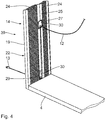
- Fig. 4 shows a further embodiment of a furniture element 39.
- Components that correspond to those described above with reference to the Fig. 1 to 3 have the same reference numbers and will not be discussed again in detail.
- the main difference is that in the furniture element 39, the second opening 29 is arranged on the first side surface 19 of the furniture element 39.
- the second opening 29 of the cable channel 25 is accessible via a side surface opening 28 in the first side cover plate 16 and covered by a cap 30.
- the first opening 27 is analogous to the first embodiment via a side surface opening 28 on the second side surface of the second side cover plate, which for purposes of illustration in the Fig. 4 not shown, arranged.
- the first opening 27 and the second opening 29 are arranged on opposite side surfaces of the main body 14.
- the first opening 27 and the second opening 29 are not aligned along a plate thickness direction.
- the cable channel 25 is vertically oriented in the furniture element 39. Along this vertical direction, the first opening 27 and the second opening 29 are arranged offset to one another.
- the furniture element 39 has a frame 22 and honeycomb structures 24 which surround the cable duct 25.
- the frame 22 is closed on a lower side surface, that is not executed with a recess. As a result, the stability and rigidity of the frame 22 is additionally increased.
- the furniture element 39 is preferably a side wall of a furniture system such as a shelving system or a room divider. It is also conceivable that the furniture element 39 represents a rear wall of a furniture system. In this case, a cable 12 inconspicuously to the rear, in particular to a room wall on which, for example, a socket for an electrical power supply is arranged, are performed.
- Fig. 4 illustrated embodiment of the furniture element 39 so it is not necessary that the cable 12 is guided by two adjacent furniture elements.
- the cable 12 is guided over a single furniture element 39 to the outside, ie out of the furniture system 1 out.
- Fig. 5 and 6 show a further embodiment of a furniture element 40.
- the cable channel 42 is formed by two stiffening elements 41 are arranged as a boundary on the honeycomb structures 24.
- the stiffening elements 41 are each designed as MDF strips having a width b, which corresponds to a thickness d of the honeycomb structures 24. This means that the stiffening elements 41 serve as additional stiffening of the structural layer.
- the stiffening elements can also be made of a different material.
- the remaining between the stiffening elements 41 space forms the cable channel 42.
- the cable channel 42 is particularly uncomplicated. In particular, the use of a complex shaped profile element is not required.
- the side surfaces 19, 20 facing surfaces of the cable channel 42 omitted.
- the cable channel 42 is open within the structural layer 15 to the side surfaces 19, 20.
- the frame 22 does not have the above arranged transverse element.
Landscapes
- Tables And Desks Characterized By Structural Shape (AREA)
- Details Of Indoor Wiring (AREA)
- Chair Legs, Seat Parts, And Backrests (AREA)
Description
- Die Erfindung betrifft ein Möbelsystem mit einem Möbelelement.
- Ein aus der
DE 36 36 743 A1 bekanntes Möbelsystem offenbart ein Regalsystem zur Aufbewahrung von Gegenständen wie beispielsweise Bücher, Dekorationsartikel und/oder Geräte der Unterhaltungselektronik, insbesondere TV-Geräte, Musikanlagen, Telefonanlagen und Computer. Eine für die Elektrogeräte erforderliche Verkabelung dient, insbesondere zur Stromversorgung, aber auch um einzelne Gerätekomponenten miteinander zu verbinden. - Die
DE 10 2010 000 321 A1 offenbart Leichtbaumöbelteile mit einer Rahmenstruktur und einer innenliegenden Mittelschicht. Derartige Leichtbaumöbel sind komplex aufgebaut. DieWO 2006/100 295 offenbart eine Möbelplatte mit einer aus Wabenmaterial bestehenden Kernlage. DieDE 10 2011 108 974 A1 betrifft eine individuell gefertigte Funktionsplatte mit integrierten Kabelführungen. - Es ist die Aufgabe der vorliegenden Erfindung, ein Möbelsystem derart zu verbessern, dass beliebige Gegenstände in dem Möbelsystem vorteilhaft, insbesondere ästhetisch ansprechend, angeordnet werden können.
- Diese Aufgabe wird durch ein ein Möbelelement aufweisendes Möbelsystem mit den Merkmalen des Anspruchs 1 gelöst. Der Kern der Erfindung liegt darin, dass ein Möbelsystem mindestens ein Möbelelement umfasst, das einen plattenförmigen Grundkörper mit einem innerhalb des Grundkörpers angeordneten Kabelkanal aufweist. Als Möbelsystem im Sinne dieser Anmeldung werden Möbel verstanden, die mindestens ein erfindungsgemäßes Möbelelement umfassen. Ein derartiges Möbelsystem kann beispielsweise ein Regalsystem, insbesondere in Form eines Raumteilers, sein, das mindestens einen, vorzugsweise horizontal orientierten, Einlegeboden aufweist, auf dem Gegenstände abgestellt werden können. Ein derartiges Regalsystem weist mindestens ein erfindungsgemäßes Möbelelement auf, das vorzugsweise vertikal orientiert ist. Ein derartiges Regalsystem kann beispielsweise freistehend im Raum angeordnet sein oder an einer Wand befestigt werden. Weitere Möbelsysteme sind beispielsweise Schränke, Schrankwände, Garderoben, Vitrinen, Tische, Betten, Schreibtische, Sitzbänke, Kommoden, TV-Boards, Lowboards und Phonomöbel. Durch den Kabelkanal kann eine Verkabelung geführt werden, die insbesondere zur Stromversorgung elektronischer Geräte und/oder zur Verbindung von Geräten beispielsweise durch Datenkabel oder Lautsprecherkabel erforderlich ist. Die Verkabelung ist von außerhalb des Möbelelements nicht zu sehen. Die Verkabelung ist versteckt angeordnet. Ein derartiges Möbelelement ermöglicht eine vorteilhafte Kabelführung, die insbesondere höchsten ästhetischen Ansprüchen eines Nutzers entspricht. Der Kabelkanal weist mindestens eine erste Öffnung, welche insbesondere benachbart zu dem elektronischen Endgerät angeordnet ist, und eine zweite Öffnung, die insbesondere benachbart zu einer Stromversorgung angeordnet ist, auf. Die erste Öffnung dient insbesondere dem Zuführen eines Kabels, insbesondere eines Stromkabels. Die zweite Öffnung dient insbesondere dem Ausführen des Kabels, insbesondere des Stromkabels, aus dem Kabelkanal. Der plattenförmige Grundkörper weist eine erste Seitenfläche und eine der ersten Seitenfläche gegenüberliegende zweite Seitenfläche auf. Insbesondere sind die Seitenflächen parallel zueinander orientiert. Das bedeutet, dass der Grundkörper eine konstante Plattendicke aufweist. Die Seitenflächen sind miteinander über eine Stirnfläche verbunden. Die Stirnfläche umfasst mehrere Stirnflächenabschnitte, die sich entlang des Umfangs der Stirnfläche erstrecken. Insbesondere ist der Kabelkanal zwischen den Seitenflächen des Grundkörpers angeordnet. Die Öffnungen, also die mindestens erste Öffnung und die mindestens zweite Öffnung sind über die Seitenflächen und/oder über die Stirnfläche des Grundkörpers zugänglich.
- Bei dem Möbelsystem ist ein mit dem Grundkörper verbundenes Standelement zum definierten Abstellen des Möbelsystems auf einer Unterlage vorgesehen.
- Das Möbelelement weist einen Schichtaufbau des Grundkörpers auf, insbesondere in Sandwichbauweise. Der Grundkörper weist eine innenliegende Strukturschicht auf, die von einer ersten Seitendeckplatte und einer gegenüberliegenden zweiten Seitendeckplatte abgedeckt ist. Zusätzlich kann eine Stirnseitenabdeckung vorgesehen sein, um die Stirnseite der Strukturschicht abzudecken. Eine derartige Ausführung des Grundkörpers ermöglicht eine effektive funktionale Trennung der jeweiligen Schichten im Grundkörper. Insbesondere ermöglicht die Strukturschicht, dass der Grundkörper eine besonders steife und stabile Struktur aufweist. Gleichzeitig ermöglichen die Seitendeckplatten eine ästhetisch ansprechende Gestaltung des Möbelelements. Insbesondere können die Seitendeckplatten in verschiedenen Ausgestaltungen, insbesondere in verschiedenen Farben, Mustern und/oder Motiven bereitgestellt werden, um ein Möbelelement nach den Wünschen eines Kunden gestalten zu können. Bei den Seitendeckplatten kann es sich um hinterspritzte Kunststofffolien handeln. Die Seitendeckplatten können mit der Strukturschicht verklebt sein.
- Die Strukturschicht weist ein festigkeitssteigerndes Strukturelement, insbesondere einen Rahmen, auf. Der Rahmen kann insbesondere außenliegend angeordnet sein. Der Rahmen ist insbesondere ein massiv ausgeführter Riegel. Zusätzlich weist die Strukturschicht ein aussteifendes Strukturelement auf, das insbesondere durch eine Wabenstruktur ausgeführt ist. Das aussteifende Strukturelement weist ein geringes Gewicht auf, ist also leichtbauend ausgeführt. Gleichzeitig weist das aussteifende Strukturelement eine hohe Eigensteifigkeit auf, insbesondere gegenüber einer Biegung aus der Plattenebene des plattenförmigen Grundkörpers heraus. Insbesondere ist das aussteifende Strukturelement innenliegend angeordnet und insbesondere von dem festigkeitssteigernden Strukturelement zumindest teilweise umgeben. Die beiden Strukturelemente können miteinander verklebt sein. Bei der Strukturschicht sind die Funktionen Festigkeitssteigerung und Aussteifung auf zwei Strukturelemente aufgeteilt, so dass beide Funktionen zielführend erfüllt sind. Insbesondere ist es nicht erforderlich, die gesamte Fläche des Grundkörpers mit einem festigkeitssteigernden Strukturelement auszufüllen. Es ist ausreichend, wenn das festigkeitssteigernde und gleichzeitig aussteifende Strukturelement einen zumindest abschnittsweise umlaufenden Rahmen ausreichender Festigkeit bereitstellt. Insbesondere ist das aussteifende Strukturelement leichtbauend ausgeführt, so dass das Gesamtgewicht der Strukturschicht und somit das Gesamtgewicht des Möbelelements reduziert ist.
- Der Kabelkanal ist in die Strukturschicht, und insbesondere in die Wabenstruktur, integriert. Der Kabelkanal ist innerhalb des Grundkörpers geschützt. Dadurch, dass der Kabelkanal durch die Strukturschicht umgeben ist, ist der Kabelkanal definiert innerhalb des Grundkörpers positioniert.
- Besonders vorteilhaft ist ein Möbelelement, bei dem der Kabelkanal als Profilelement, insbesondere als Kunststoff-Profilelement, ausgeführt ist. Der Kabelkanal weist dadurch eine Eigensteifigkeit auf. Der Kabelkanal ist robust ausgeführt. Es ist grundsätzlich auch denkbar, dass der Kabelkanal keine eigene Einhausung in Form eines Profilelements aufweist. In diesem Fall kann der Kabelkanal durch umgebende Elemente, insbesondere durch die Strukturschicht und insbesondere die erste und zweite Seitendeckplatte umgeben sein.
- Alternativ kann bei dem Möbelelement der Kabelkanal dadurch ausgeführt sein, dass mindestens ein zusätzliches Versteifungselement vorgesehen ist. Das mindestens eine zusätzliche Versteifungselement begrenzt einen Hohlraum des Kabelkanals gegenüber der Strukturschicht. Insbesondere sind mindestens zwei zusätzliche Versteifungselemente vorgesehen, die leistenartig ausgeführt sind. Die Leisten weisen eine Breite auf, die einer Dicke der Strukturschicht entspricht. Die Leisten bilden eine Versteifung zwischen der ersten und der zweiten Seitenfläche des Grundkörpers. Bei dieser Ausführung ist besonders vorteilhaft, dass ein aufwendig gestaltetes Profilelement für die Verwirklichung des Kabelkanals nicht erforderlich ist. Die zusätzlichen Versteifungselemente können insbesondere als Leisten aus einer mitteldichten Holzfaserplatter hergestellt sein.
- Bei einem Möbelelement, bei dem mindestens zwei erste Öffnungen vorgesehen sind, die paarweise fluchtend angeordnet sind und über die Seitenflächen des Grundkörpers zugänglich sind, werden einem Nutzer des Möbelsystems vielfältige Möglichkeiten beim Verlegen der Verkabelung geschaffen. Insbesondere bei einem Möbelsystem, das beispielsweise als Regalsystem ausgeführt sein kann und einen optisch durchgängigen Regalboden aufweist, der sich beidseitig, also an beiden Seitenflächen des Grundkörpers des Möbelelements anschließt, ist die Flexibilität bei der Anordnung der elektronischen Geräte vergrößert. Das elektronische Gerät kann beispielsweise auf beiden Seiten des Möbelelements angeordnet sein. Eine Zuführung über beide Seitenflächen in den Kabelkanal ist möglich.
- Bei einem Möbelelement, bei dem der Kabelkanal eine lineare Kabelkanal-Längsachse aufweist, ist die Durchführung eines Kabels durch den Kabelkanal vereinfacht.
- Vorteilhaft ist es, wenn ein Möbelelement eine auf den Grundkörper aufsetzbare, die erste Öffnung abdeckbare Abdeckkappe aufweist. Insbesondere ist die Abdeckkappe mit einer randseitig offenen Abdeckkappen-Öffnung ausgeführt. Dadurch ist es möglich, die erste Öffnung abzudecken, so dass ein Zugang zu dem Kabelkanal im Wesentlichen und insbesondere unbeabsichtigt nicht möglich ist. Gleichzeitig ist der ästhetische Gesamteindruck des Möbelelements verbessert, da die Kabelführung und insbesondere die Zuführung der Verkabelung in den Kabelkanal nicht sichtbar ist. Die erste Öffnung muss mindestens so groß sein, dass nicht nur das Kabel selbst, sondern insbesondere der Stecker für den Anschluss an eine Stromversorgung oder an ein weiteres Gerät durch die Öffnung hindurchgeführt werden kann. Die Abdeckkappe ermöglicht ein Abdecken der ersten Öffnung. Mittels der randseitig offenen Abdeckkappenöffnung kann das Kabel aus der mit der Abdeckkappe abgedeckten ersten Öffnung herausgeführt werden. Insbesondere kann die Abdeckkappe Rastelemente aufweisen, die mit der ersten Öffnung derart zusammenwirken, dass die Abdeckkappe sicher, insbesondere gegen unbeabsichtigtes Herausziehen, in der Öffnung gehalten ist.
- Vorteilhaft ist ein Möbelelement, bei dem die Abdeckkappe eine der Abdeckkappen-Öffnung gegenüberliegend angeordnete Abdeckkappen-Schwenkachse aufweist. Dadurch ist es möglich, dass die Abdeckkappe beispielsweise mit einem Abdeckkappen-Rahmen an der ersten Öffnung des Möbelelements befestigt bleibt, wobei ein gegenüber dem Abdeckkappenrahmen schwenkbarer Abdeckkappendeckel geschwenkt werden kann, um einem Bediener des Möbelelements einen Zugang zum Kabelkanal zu vereinfachen. Insbesondere ist es nicht erforderlich, die Abdeckkappe von der ersten Öffnung zu entfernen.
- Vorteilhaft ist ein Möbelelement mit mindestens einem Verbindungselement des Grundkörpers zum Verbinden mit mindestens einem weiteren Element. Bei dem weiteren Element kann es sich beispielsweise um ein weiteres Möbelelement im Sinne der vorliegenden Anmeldung handeln. Das weitere Element kann auch ein Standelement bzw. ein Fußelement, ein Deckel und/oder ein Einlegeboden sein. Als Verbindungselement dient insbesondere ein Zapfen, ein Schraubverbinder, eine Bohrung zur Aufnahme eines Zapfens oder ähnliche.
- Besonders bevorzugt ist das mindestens eine Verbindungselement benachbart zu der ersten Öffnung angeordnet. Dadurch ist es möglich, dass benachbart zu der ersten Öffnung beispielsweise ein Einlegeboden für ein Regalsystem vorgesehen sein kann. Auf einem derartigen Einlegeboden kann dann ein elektronisches Gerät angeordnet sein. Aufgrund der benachbarten Anordnung der ersten Öffnung zu den Verbindungselementen ist die erste Öffnung auch benachbart zu dem Einlegeboden angeordnet. Ein Kabel kann vorteilhaft und optisch ansprechend in dem Möbelelement versteckt werden.
- Vorteilhaft ist ein Möbelelement, bei dem die Seitendeckplatten jeweils mindestens eine Seitenflächenöffnung aufweisen, die langlochförmig ausgeführt ist. Der Aufwand der Herstellung einer derartigen ersten Seitenflächenöffnung ist deutlich reduziert. Insbesondere ist der Maschinenaufwand reduziert. Die langlochförmige erste Seitenflächenöffnung kann beispielsweise im Durchlauf hergestellt werden. Es ist nicht erforderlich, ein Bearbeitungszentrum zu nutzen. Die Einsparung des Zeitaufwands zur Herstellung der ersten Seitenflächenöffnung ist um etwa 95% reduziert. Die Seitenflächenöffnung kann auch rund, rechteckig, quadratisch, dreieckig, sechseckig oder achteckig ausgeführt sein.
- Vorteilhaft ist, wenn das Standelement parallel zu der Unterlage ausgerichtet und insbesondere horizontal orientiert ist. Das Möbelelement ist derart angeordnet, dass der Kabelkanal im Wesentlichen vertikal orientiert ist. Eine Neigung von bis zu 15° gegenüber der Vertikalen ist als im Wesentlichen vertikal orientiert im Sinne dieser Anmeldung zu verstehen.
- Vorteilhaft ist ein Möbelsystem, bei dem das Standelement einen Durchgangskanal mit einer, mit der zweiten Öffnung korrespondierenden, ersten Standelement-Öffnung und mit einer zweiten Standelement-Öffnung aufweist. Ein derartiges Möbelsystem ermöglicht eine Verbindung des Kabelkanals des Möbelelements mit dem Durchgangskanal des Standelements derart, dass ein durchgängiger Kanal zur Durchführung einer Verkabelung gebildet wird. Vorzugsweise sind die Standelement-Öffnungen an einer Ober- und Unterseite des vorzugsweise horizontal angeordneten Standelements vorgesehen. Eine Verkabelung kann durch das Standelement hindurchgeführt und an einer Unterseite des Standelements, das insbesondere ein Bodenelement des Möbelsystems darstellt, abgeführt und unterhalb des Möbelsystems geführt werden. Die Verkabelung ist einerseits optisch unauffällig und andererseits vereinfacht zugänglich verlegt.
- Sowohl die in den Patentansprüchen angegebenen Merkmale als auch die in dem nachfolgenden Ausführungsbeispiel des erfindungsgemäßen Möbelelements angegebenen Merkmale sind jeweils für sich alleine oder in Kombination miteinander geeignet, den erfindungsgemäßen Gegenstand weiterzubilden. Die jeweiligen Merkmalskombinationen stellen hinsichtlich der Weiterbildungen des Erfindungsgegenstands keine Einschränkung dar, sondern weisen im Wesentlichen lediglich beispielhaften Charakter auf.
- Weitere Merkmale, Vorteile und Einzelheiten der Erfindung ergeben sich aus der nachfolgenden Beschreibung von Ausführungsbeispielen anhand der Zeichnung. Es zeigen:
- Fig. 1
- eine Frontansicht eines Möbelsystems mit einem Möbelelement gemäß einem Ausführungsbeispiel der Erfindung,
- Fig. 2
- eine perspektivische Explosionsdarstellung des Möbelelements in
Fig. 1 , - Fig. 3
- eine perspektivische Darstellung des Möbelelements in
Fig. 2 , - Fig. 4
- eine vergrößerte perspektivische Ausschnittsdarstellung eines weiteren Ausführungsbeispiels der Erfindung,
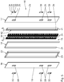
- Fig. 5
- eine
Fig. 2 entsprechende perspektivische Explosionsdarstellung eines Möbelelements gemäß einer weiteren Ausführungsform der Erfindung und - Fig. 6
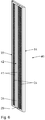
- eine
Fig. 3 entsprechende perspektivische Darstellung des Möbelelements inFig. 5 . - Im Folgenden wird anhand der
Fig. 1 bis Fig. 3 ein erstes Ausführungsbeispiel der Erfindung beschrieben. - Ein in
Fig. 1 als Ganzes dargestelltes Möbelsystem 1 ist als Regalsystem, insbesondere in der Form eines Raumteilers, ausgeführt. - Das Möbelsystem 1 ist rasterartig aufgebaut. Das Möbelsystem 1 umfasst zwei vertikal orientierte Seitenwände 2, einen auf Füßen 3 angeordneten Boden 4 sowie einen Deckel 5. Mit den Füßen 3 ist der Boden 4, der ein Standelement darstellt, definiert auf einem Untergrund 6 abgestellt. Aufgrund der Füße 3 ist eine Unterseite des Bodens 4 beabstandet zu dem Untergrund 6 angeordnet. Ein zwischen dem Boden 4 und dem Untergrund 6 resultierender Zwischenraum 7a weist eine Höhe h auf, die durch die Höhe der Füße 3 festgelegt ist.
- Zwischen dem Deckel 5 und dem Boden 4 sind zwei parallel zu den Seitenwänden 2 orientierte Möbelelemente 7 angeordnet. Zwischen jeweils einer Seitenwand 2 und einem Möbelelement 7 sowie zwischen den beiden Möbelelementen 7 sind mehrere Querböden 8 angeordnet. Die Querböden 8 dienen dazu, um Gegenstände wie beispielsweise Dekorationsgegenstände 9 und elektronische Geräte 10 abzustellen. Als elektronische Geräte 10 sind gemäß dem gezeigten Ausführungsbeispiel ein TV-Gerät, eine Stehlampe, ein DVD-Player und eine Musikanlage dargestellt.
- In einem mittleren Bereich des Möbelsystems 1 zwischen zwei Querböden 8 und zwei Möbelelementen 7 ist eine Rückwand 11 angeordnet. Die weiteren Fächer des Möbelsystems 1 weisen keine Rückwand auf.
- Die elektronischen Geräte 10 benötigen eine Verbindung mit einer elektrischen Spannungsquelle. Dazu weisen die elektrischen Geräte jeweils ein stromführendes Kabel 12 mit Stecker 13 auf. Zusätzlich können weitere Kabelverbindungen vorgesehen sein, die im Einzelnen nicht dargestellt sind. Diese zusätzlichen Kabelverbindungen können dazu dienen, um beispielsweise den DVD-Recorder mit dem TV-Gerät zur Signalübertragung zu verbinden.
- Die Kabel 12 sind durch das in
Fig. 1 geschnitten dargestellte, linke Möbelelement 7 nach unten zu dem Boden 4 hin, durch den Boden 4 hindurch in den Zwischenraum 7a geführt. Dazu weist der Boden 4 einen Durchgangskanal 36 auf, der eine erste Standelement-Öffnung 37 und eine zweite Standelement-Öffnung 38 aufweist. Die erste Standelement-Öffnung 37 ist dem Möbelelement 7 zugewandt. Die erste Standelement-Öffnung 37 ist an einer Oberseite des Bodens 4 vorgesehen. Die zweite Standelement-Öffnung 38 ist an der Unterseite des Bodens 4, also dem Zwischenraum 7a zugewandt, angeordnet. Die Standelement-Öffnungen 37, 38 sind entlang einer Längsachse des Durchgangskanals 36 fluchtend angeordnet. Die Kabel 12 sind im Bereich des Zwischenraums 7a zur Seite nach links herausgeführt, so dass die Stecker 13 außerhalb des Möbelsystems 1 angeordnet sind. Die Stecker 13 können in eine Steckdose einer Spannungsquelle zur Stromversorgung der elektronischen Geräte 10 gesteckt werden. - Nachfolgend wird anhand der
Fig. 2 und3 der Aufbau des Möbelelements 7 zur Kabeldurchführung näher erläutert. Das Möbelelement 7 weist einen plattenförmigen Grundkörper 14 auf, der schichtweise aufgebaut ist. Der Grundkörper 14 weist eine sogenannte Sandwich-Struktur auf. Der Grundkörper 14 umfasst eine innenliegende Strukturschicht 15, eine erste, inFig. 2 links dargestellte Seitendeckplatte 16 und eine zweite, inFig. 2 rechts dargestellte Seitendeckplatte 17 sowie eine im Wesentlichen umlaufende Stirnseitenabdeckung 18. Die erste Seitendeckplatte 16 weist eine nach außen gerichtete erste Seitenfläche 19 auf. Die zweite Seitendeckplatte 17 weist eine der ersten Seitenfläche 19 abgewandte und gegenüberliegend angeordnete zweite Seitenfläche 20 auf. Die Seitendeckplatten 16, 17 sind im Wesentlichen identisch ausgeführt. Die Seitendeckplatten 16, 17 sind insbesondere aus einer mitteldichten Holzfaserplatte MDF hergestellt. Die Seitendeckplatten 16, 17 weisen beispielsweise eine Dicke von 2 mm bis 6 mm auf. Die Stirnseitenabdeckung 18 umfasst zwei vertikale Stirnflächenabschnitte und einen, die beiden vertikalen Stirnflächenabschnitte verbindenden horizontalen Stirnflächenabschnitt. Es ist auch möglich, dass ein zweiter horizontaler Stirnflächenabschnitt vorgesehen ist, der dem ersten, oberen horizontalen Stirnflächenabschnitt gegenüberliegend an einer Unterseite der Stirnseitenabdeckung 18 angeordnet ist. Ein derartiger unterer, horizontaler Stirnflächenabschnitt, der inFig. 2 und3 nicht dargestellt ist, bildet einen unteren Abschluss der Stirnseitenabdeckung. Die horizontalen und vertikalen Stirnflächenabschnitte bilden gemeinsam eine Stirnfläche 21 der Stirnflächenabdeckung 18. Die Stirnfläche 21 ist nach außen gewandt. - Die Strukturschicht 15 umfasst einen im Wesentlichen umlaufenden Rahmen 22. Der Rahmen 22 ist gemäß dem gezeigten Ausführungsbeispiel aus hochdichtem Holzfaserplatten-Werkstoff HDF mit einer Dichte von mindestens 800 kg/m3 hergestellt. Es sind auch andere Werkstoffe zur Herstellung des Rahmens 22 denkbar. Der Rahmen 22 ist im Wesentlichen rechteckförmig ausgeführt und weist eine Aussparung 23 auf. Der Rahmen 22 ist aus Massivwerkstoff in Form eines umlaufenden Riegels hergestellt. Der Rahmen 22 ist in der Strukturschicht 15 außenliegend angeordnet. Der Rahmen 22 bildet ein festigkeitssteigerndes Strukturelement.
- Die Strukturschicht 15 weist weiterhin ein aussteifendes Strukturelement in Form einer Wabenstruktur 24 auf. Die Wabenstruktur 24 ist aus Pappe hergestellt. Es sind auch andere Materialien wie beispielsweise Papier, Aluminium und/oder Kunststofffolie zur Herstellung der Wabenstruktur 24 denkbar. Die Wabenstruktur weist ein reduziertes Gewicht und trotzdem eine hohe Steifigkeit auf. Die Wabenstruktur 24 ist leichtbauend ausgeführt. Aufgrund der Hohlräume in der Wabenstruktur weist diese isolierende Eigenschaften, insbesondere zur thermischen und akustischen Isolation, auf. Gemäß dem gezeigten Ausführungsbeispiel ist die Wabenstruktur 24 zweiteilig ausgeführt mit zwei Wabenstruktur-Elementen, die beabstandet zueinander angeordnet sind.
- Zwischen den beiden Wabenstruktur-Elementen ist ein Kunststoff-Profilelement 25 als Kabelkanal vorgesehen. Der Kabelkanal 25 weist eine lineare Kabelkanal-Längsachse 26 auf. In einer Ebene senkrecht zur Kabelkanal-Längsachse 26 weist der Kabelkanal 25 einen rechteckförmigen Querschnitt auf. Es sind auch andere Querschnittsformen für den Kabelkanal 25 denkbar. Es ist zudem denkbar, dass die beiden Wabenstruktur-Elemente der Wabenstruktur 24 miteinander verbunden sind, beispielsweise in einem oberen, dem horizontalen Stirnflächenabschnitt zugewandten Bereich. Der Kabelkanal weist sechs erste Öffnungen 27 auf. Die ersten Öffnungen 27 dienen jeweils als Zuführöffnung, um ein Kabel 12 eines elektronischen Geräts 10 dem Kabelkanal 25 zuzuführen. Die ersten Öffnungen 27 sind jeweils paarweise an Seitenwänden 35 des Kabelkanals 25 fluchtend und gegenüberliegend angeordnet. Das bedeutet, dass der Kabelkanal 25 gemäß dem gezeigten Ausführungsbeispiel drei Paare von gegenüberliegend angeordneten ersten Öffnungen 27 aufweist.
- Das Möbelelement 7 ist gemäß der Board and Frame-Technologie hergestellt.
- Die Seitendeckplatten 16, 17 weisen jeweils drei Seitenflächen-Öffnungen 28 auf, über die die ersten Öffnungen 27 des Kabelkanals 25 zugänglich sind. Gemäß dem gezeigten Ausführungsbeispiel sind die Seitenflächenöffnungen 28 in den Seitendeckplatten 16, 17 rechteckförmig ausgeführt. Insbesondere aus fertigungstechnischen Gründen ist es vorteilhaft, die Seitenflächenöffnungen 28 langlochförmig auszuführen. Der Kabelkanal 25 weist zudem eine zweite Öffnung 29 auf. Gemäß dem gezeigten Ausführungsbeispiel ist die zweite Öffnung 29 an einer unteren Stirnseite des Kabelkanals 25 angeordnet. Die zweite Öffnung 29 ist in einer Ebene senkrecht zur Kabelkanal-Längsachse 26 angeordnet. Die ersten Öffnungen 27 sind gemäß dem gezeigten Ausführungsbeispiel in einer Ebene parallel zur Kabelkanal-Längsachse 26 angeordnet.
- Insbesondere aus der Darstellung gemäß
Fig. 3 , in der die Seitendeckplatten 16, 17 aus Gründen der besseren Darstellung nicht gezeigt sind, wird klar, dass der Kabelkanal 25 zwischen den beiden Elementen der Wabenstruktur 24 eingepasst ist. Der Kabelkanal 25 ist mit einem unteren Ende im Bereich der zweiten Öffnung 29 in der Aussparung 23 des Rahmens 22 angeordnet. Das bedeutet, dass die zweite Öffnung 29 über die Aussparung 23 im Bereich der Stirnfläche 21 des Grundkörpers 14 zugänglich ist. - Es ist auch möglich, auf das Kunststoff-Profilelement als Kabelkanal zu verzichten. In diesem Fall wird der Kabelkanal 25 als Hohlraum zwischen den beiden Elementen der Wabenstruktur 24 einerseits und zwischen den beiden Seitendeckplatten 16, 17 andererseits sowie dem Rahmen 22 gebildet.
- Selbstverständlich ist es auch möglich, dass die in den Seitenwänden 35 des Kabelkanals 25 vorgesehenen Öffnungen als zweite Öffnungen im Sinne der Anmeldung dienen, beispielsweise dann, wenn eine Stromversorgung in einem Möbelsystem integriert ist oder ein Verbindungskabel zur Datenübertragung von einem ersten elektronischen Gerät zu einem zweiten elektronischen Gerät geführt werden soll.
- Anstelle der Wabenstruktur 24 ist auch eine andere aussteifende Struktur denkbar.
- Insbesondere ist der Kabelkanal 25 mit der Wabenstruktur und/oder dem Rahmen 22 verklebt.
- Auf die Seitenflächenöffnungen 28 in den Seitendeckplatten 16, 17 ist jeweils eine Abdeckkappe 30 aufgesetzt und insbesondere in der Seitenflächenöffnung 28 und/oder der ersten Öffnung 27 verrastet. Die erste Öffnung 27 ist durch die aufgesetzte Abdeckkappe 30 abgedeckt. Die Abdeckkappe 30 weist einen Abdeckkappen-Rahmen 31 auf. Weiterhin weist die Abdeckkappe 30 eine randseitig offene Abdeckkappen-Öffnung 32 auf. Der Abdeckkappen-Öffnung 32 gegenüberliegend ist eine Abdeckkappen-Schwenkachse 33 vorgesehen, um die ein Abdeckkappen-Deckel 34 der Abdeckkappe 30 an dem Abdeckkappen-Rahmen 31 schwenkbar ist. Gemäß dem gezeigten Ausführungsbeispiel ist die Abdeckkappen-Schwenkachse 33 horizontal orientiert. Es ist auch denkbar, dass die Abdeckkappen-Schwenkachse 33 vertikal orientiert ist. Durch die Abdeckkappen-Öffnung 32 kann das Kabel 12 geführt werden, wenn der Abdeckkappen-Deckel 34 geschlossen ist.
- Insbesondere ist das Standelement 4 im Wesentlichen analog dem Möbelelement 7 ausgeführt. Die Standelement-Öffnungen 37, 38 entsprechen den Öffnungen 27, 29, über die der Durchgangskanal 36 zugänglich ist. Der Durchgangskanal 36 ist ein Kabelkanal. Die Verkabelung wird über die Standelement-Öffnung 37 zu- und über die an der gegenüberliegenden Seite angeordnete Standelement-Öffnung 38 abgeführt. Der Grundkörper selbst, also die Seitenflächen, die Stirnfläche sowie der Schichtaufbau des Grundkörpers des Standelements 4, entspricht dem des Möbelelements 7. Das Standelement 4 ist ein erfindungsgemäßes Möbelelement.
-
Fig. 4 zeigt eine weitere Ausführung eines Möbelelements 39. Komponenten, die denjenigen entsprechen, die vorstehend unter Bezugnahme auf dieFig. 1 bis 3 erläutert wurden, tragen die gleichen Bezugsziffern und werden nicht nochmals im Einzelnen diskutiert. - Wesentlicher Unterschied ist, dass bei dem Möbelelement 39 die zweite Öffnung 29 an der ersten Seitenfläche 19 des Möbelelements 39 angeordnet ist. Die zweite Öffnung 29 des Kabelkanals 25 ist über eine Seitenflächenöffnung 28 in der ersten Seitendeckplatte 16 zugänglich und mittels einer Abdeckkappe 30 abgedeckt. Die erste Öffnung 27 ist analog dem ersten Ausführungsbeispiel über eine Seitenflächenöffnung 28 an der zweiten Seitenfläche der zweiten Seitendeckplatte, die aus Darstellungsgründen in der
Fig. 4 nicht gezeigt ist, angeordnet. Die erste Öffnung 27 und die zweite Öffnung 29 sind an gegenüberliegenden Seitenflächen des Grundkörpers 14 angeordnet. Die erste Öffnung 27 und die zweite Öffnung 29 sind entlang einer Plattendickenrichtung nicht fluchtend angeordnet. Der Kabelkanal 25 ist in dem Möbelelement 39 vertikal orientiert. Entlang dieser vertikalen Richtung sind die erste Öffnung 27 und die zweite Öffnung 29 versetzt zueinander angeordnet. Dadurch, dass die zweite Seitendeckplatte mit der zweiten Seitenfläche nicht dargestellt ist, ist der Aufbau des Möbelelements 39 sichtbar. Analog dem Möbelelement gemäß dem ersten Ausführungsbeispiel weist das Möbelelement 39 einen Rahmen 22 und Wabenstrukturen 24 auf, die den Kabelkanal 25 umgeben. Insbesondere ist der Rahmen 22 an einer unteren Seitenfläche geschlossen, also nicht mit einer Aussparung ausgeführt. Dadurch ist die Stabilität und Steifigkeit des Rahmens 22 zusätzlich erhöht. - Bei dem Möbelelement 39 handelt es sich vorzugsweise um eine Seitenwand eines Möbelsystems wie beispielsweise eines Regalsystems oder eines Raumteilers. Es ist auch denkbar, dass das Möbelelement 39 eine Rückwand eines Möbelsystems darstellt. In diesem Fall kann ein Kabel 12 unauffällig nach hinten, insbesondere zu einer Raumwand, an der beispielsweise eine Steckdose für eine elektrische Stromversorgung angeordnet ist, geführt werden.
- Bei dem in
Fig. 4 dargestellten Ausführungsbeispiel des Möbelelements 39 ist es also nicht erforderlich, dass das Kabel 12 durch zwei angrenzende Möbelelemente geführt wird. Das Kabel 12 wird über ein einziges Möbelelement 39 nach außen, also aus dem Möbelsystem 1 heraus geführt. -
Fig. 5 und6 zeigen eine weitere Ausführung eines Möbelelements 40. Komponenten, die denjenigen entsprechen, die vorstehend unter Bezugnahme auf dieFig. 1 bis 4 erläutert wurden, tragen die gleichen Bezugsziffern und werden nicht nochmals im Einzelnen diskutiert. Wesentlicher Unterschied des Möbelelements 40 gegenüber dem inFig. 1 bis 3 dargestellten ist die Ausführung des Kabelkanals 42. Der Kabelkanal 42 ist dadurch gebildet, dass zwei Versteifungselemente 41 als Begrenzung an den Wabenstrukturen 24 angeordnet sind. Die Versteifungselemente 41 sind jeweils als MDF-Leisten mit einer Breite b ausgeführt, die einer Dicke d der Wabenstrukturen 24 entspricht. Das bedeutet, dass die Versteifungselemente 41 als zusätzliche Versteifung der Strukturschicht dienen. Die Versteifungselemente können auch aus einem anderen Material hergestellt sein. Der zwischen den Versteifungselementen 41 verbleibende Freiraum bildet den Kabelkanal 42. Der Kabelkanal 42 ist besonders unkompliziert ausgeführt. Insbesondere ist die Verwendung eines komplex geformten Profilelements nicht erforderlich. Die den Seitenflächen 19, 20 zugewandten Oberflächen des Kabelkanals 42 entfallen. Der Kabelkanal 42 ist innerhalb der Strukturschicht 15 zu den Seitenflächen 19, 20 offen. - Es ist denkbar, dass der Rahmen 22 das oben angeordnete Querelement nicht aufweist.
Claims (12)
- Möbelsystem (1) mit mindestens einem Möbelelement (4, 7, 39; 40) umfassend einen plattenförmigen Grundkörper (14) mita. einer ersten Seitenfläche (19),b. einer der ersten Seitenfläche (19) gegenüberliegenden zweiten Seitenfläche (20),c. einer die Seitenflächen (19, 20) miteinander verbindende Stirnfläche (21),d. einem innerhalb des Grundkörpers (14) angeordneten Kabelkanal (25; 42), der mindestensi. eine erste Öffnung (27) undii. eine zweite Öffnung (29) aufweist, wobei die Öffnungen (27; 29) über die Seitenflächen (19, 20) und/oder die Stirnfläche (21) zugänglich sind, unde. einem Schichtaufbau des Grundkörpers (14) mit einer innen liegenden Strukturschicht (15), einer ersten Seitendeckplatte (16), einer zweiten Seitendeckplatte (17),
wobeif. die Strukturschicht (15) ein festigkeitssteigerndes Strukturelement und ein aussteifendes Strukturelement in Form einer Wabenstruktur (24) aufweist, undg. der Kabelkanal (25; 42) in die Strukturschicht (15) integriert ist,ein mit dem Grundkörper (14) verbundenes Standelement (4), das zum definierten Abstellen des Möbelsystems (1) auf einer Unterlage (6) dient.
gekennzeichnet durch - Möbelsystem nach Anspruch 1, dadurch gekennzeichnet, dass der Kabelkanal (25) als Profilelement, insbesondere als Kunststoff-Profilelement, ausgeführt ist.
- Möbelsystem nach Anspruch 1, dadurch gekennzeichnet, dass der Kabelkanal (42) durch mindestens ein Versteifungselement (41) gegenüber der Strukturschicht (15), insbesondere gegenüber der Wabenstruktur (24) begrenzt ist.
- Möbelsystem nach einem der vorstehenden Ansprüche, gekennzeichnet durch mindestens zwei erste Öffnungen (27), die paarweise fluchtend, insbesondere an gegenüberliegenden Seitenwänden (35) des Kabelkanals (25; 42), angeordnet und über die Seitenflächen (19, 20) zugänglich sind.
- Möbelsystem nach einem der vorstehenden Ansprüche, dadurch gekennzeichnet, dass der Kabelkanal (25; 42) eine lineare Kabelkanal-Längsachse (26) aufweist.
- Möbelsystem nach einem der vorstehenden Ansprüche, gekennzeichnet durch eine auf den Grundkörper (14) aufsetzbare, die erste Öffnung (27) abdeckbare Abdeckkappe (30) mit einer, insbesondere randseitig offenen, Abdeckkappen-Öffnung (32).
- Möbelsystem nach Anspruch 6, dadurch gekennzeichnet, dass die Abdeckkappe (30) eine der Abdeckkappen-Öffnung (32) gegenüberliegend angeordnete Abdeckkappen-Schwenkachse (33) aufweist.
- Möbelsystem nach einem der vorstehenden Ansprüche, gekennzeichnet durch mindestens ein Verbindungselement des Grundkörpers (14) zum Verbinden mit mindestens einem weiteren Element (2, 4, 5, 7, 8).
- Möbelsystem nach Anspruch 8, dadurch gekennzeichnet, dass das mindestens eine Verbindungselement benachbart zu der ersten Öffnung (27) angeordnet ist.
- Möbelsystem nach einem der vorstehenden Ansprüche, dadurch gekennzeichnet, dass die Seitendeckplatten (16, 17) jeweils mindestens eine Seitenflächenöffnung (28) aufweisen, die langlochförmig ausgeführt ist.
- Möbelsystem (1) nach einem der vorstehenden Ansprüche, dadurch gekennzeichnet, dass das Standelement (4) horizontal orientiert ist, wobei das Möbelelement (7, 39; 40) insbesondere derart angeordnet ist, dass der Kabelkanal (25; 42) im Wesentlichen vertikal orientiert ist.
- Möbelsystem (1) nach einem der vorstehenden Ansprüche, dadurch gekennzeichnet, dass das Standelement (4) einen Durchgangskanal (36) mit einer, mit der zweiten Öffnung (29) korrespondierenden, ersten Standelement-Öffnung (37) und mit einer zweiten Standelement-Öffnung (38) aufweist.
Priority Applications (2)
| Application Number | Priority Date | Filing Date | Title |
|---|---|---|---|
| SI201430035A SI2823732T1 (sl) | 2013-07-09 | 2014-07-07 | Pohištveni sistem s pohištvenim elementom |
| HRP20160675TT HRP20160675T1 (hr) | 2013-07-09 | 2016-06-14 | Namještajni sustav s elementom namještaja |
Applications Claiming Priority (1)
| Application Number | Priority Date | Filing Date | Title |
|---|---|---|---|
| DE102013213451.7A DE102013213451B4 (de) | 2013-07-09 | 2013-07-09 | Möbelelement für ein Möbelsystem sowie derartiges Möbelsystem |
Publications (2)
| Publication Number | Publication Date |
|---|---|
| EP2823732A1 EP2823732A1 (de) | 2015-01-14 |
| EP2823732B1 true EP2823732B1 (de) | 2016-04-13 |
Family
ID=51176141
Family Applications (1)
| Application Number | Title | Priority Date | Filing Date |
|---|---|---|---|
| EP14175922.5A Active EP2823732B1 (de) | 2013-07-09 | 2014-07-07 | Möbelsystem mit einem Möbelelement |
Country Status (7)
| Country | Link |
|---|---|
| EP (1) | EP2823732B1 (de) |
| DE (1) | DE102013213451B4 (de) |
| DK (1) | DK2823732T3 (de) |
| ES (1) | ES2574610T3 (de) |
| HR (1) | HRP20160675T1 (de) |
| PL (1) | PL2823732T3 (de) |
| SI (1) | SI2823732T1 (de) |
Families Citing this family (2)
| Publication number | Priority date | Publication date | Assignee | Title |
|---|---|---|---|---|
| DE102020125759B4 (de) * | 2020-10-01 | 2024-03-21 | ambigence GmbH & Co. KG | Möbelkomponente |
| DE102024107520B4 (de) | 2024-03-15 | 2025-09-11 | Joachim Sonnberger | Campingmöbelleichtbauplatte für den Wohnmobil- oder Caravanausbau und Campingmöbelleichtbautür oder -klappe |
Family Cites Families (6)
| Publication number | Priority date | Publication date | Assignee | Title |
|---|---|---|---|---|
| DE3636743A1 (de) * | 1986-10-29 | 1987-03-19 | Alois E Schaub Fa | Moebelstueck zur aufnahme von komponenten eines tonwiedergabesystems, insbesondere einer hifi-anlage |
| SE526646C2 (sv) * | 2004-02-12 | 2005-10-18 | Thorsman Och Co Ab | Uttagsgolvbox med kabelutlopp |
| DE102005014276A1 (de) * | 2005-03-24 | 2006-10-05 | Fritz Egger Gmbh & Co. | Bauplatte, insbesondere Möbelplatte |
| DE102010000321A1 (de) * | 2010-02-05 | 2011-08-11 | Hettich-Heinze GmbH & Co. KG, 32139 | Verbindungsanordnung |
| DE102011108974A1 (de) * | 2011-07-28 | 2013-01-31 | Stephan Hagedorn | Funktionsplatte mit integrierten Anschlüssen, Kabelführungen und Bedienelementen, welche individuell gefertigt wird |
| DE202012100493U1 (de) * | 2012-02-14 | 2012-03-28 | SPECTRAL Audio Möbel GmbH | Möbel mit einem kastenförmigen Möbelkorpus und einer daran angebrachten Bildschirmhalterung |
-
2013
- 2013-07-09 DE DE102013213451.7A patent/DE102013213451B4/de not_active Expired - Fee Related
-
2014
- 2014-07-07 DK DK14175922.5T patent/DK2823732T3/en active
- 2014-07-07 ES ES14175922.5T patent/ES2574610T3/es active Active
- 2014-07-07 SI SI201430035A patent/SI2823732T1/sl unknown
- 2014-07-07 PL PL14175922.5T patent/PL2823732T3/pl unknown
- 2014-07-07 EP EP14175922.5A patent/EP2823732B1/de active Active
-
2016
- 2016-06-14 HR HRP20160675TT patent/HRP20160675T1/hr unknown
Also Published As
| Publication number | Publication date |
|---|---|
| DE102013213451A1 (de) | 2015-01-15 |
| SI2823732T1 (sl) | 2016-08-31 |
| PL2823732T3 (pl) | 2016-09-30 |
| HRP20160675T1 (hr) | 2016-07-15 |
| DK2823732T3 (en) | 2016-07-25 |
| DE102013213451B4 (de) | 2020-08-20 |
| ES2574610T3 (es) | 2016-06-21 |
| EP2823732A1 (de) | 2015-01-14 |
Similar Documents
| Publication | Publication Date | Title |
|---|---|---|
| EP0943265B1 (de) | Schranksystem | |
| DE60220496T2 (de) | Schreibtisch und schreibtischsystem | |
| CH706175A2 (de) | Regalpfosten. | |
| DE102014001802B3 (de) | Regal- und/oder Vitrinenvorrichtung | |
| EP1891875B1 (de) | Bauplatte, insbesondere möbelplatte | |
| EP2823732A1 (de) | Möbelelement für ein Möbelsystem sowie derartiges Möbelsystem | |
| DE2321197A1 (de) | Vorrichtung zur verbindung von moebelstuecken | |
| DE102009011449B4 (de) | Möbel-oder Verkleidungsteil | |
| EP3378358B1 (de) | Möbelsystem | |
| DE102012216342B4 (de) | Arbeitsmöbel | |
| DE102012216340B4 (de) | Arbeitsmöbel | |
| DE9112637U1 (de) | Arbeitstisch | |
| DE3636743A1 (de) | Moebelstueck zur aufnahme von komponenten eines tonwiedergabesystems, insbesondere einer hifi-anlage | |
| DE102012216344B4 (de) | Arbeitsmöbel | |
| EP1142508A1 (de) | Arbeitsplatzsystem | |
| DE2911915A1 (de) | Turm zur halterung von hi-fi-geraeten und fernsehapparaten | |
| DE20301582U1 (de) | Präsentationsvorrichtung für elektronische Geräte | |
| DE202012103289U1 (de) | Möbel, insbesondere Tisch | |
| DE202021100766U1 (de) | Unterschrank-Bausatz, Sockelelement zur Verwendung in einem Unterschrank-Bausatz, und Satz von Sockelelementen | |
| DE3836997A1 (de) | Neuartiger schreibtisch-bausatz | |
| DE102010013768A1 (de) | Küchenmodul | |
| DE9105491U1 (de) | Aus einem Profilrohr bestehendes Stützbein | |
| DE8020557U1 (de) | Einbaumoebel fuer die geraete einer hifi-stereoanlage o.dgl. | |
| DE202018107268U1 (de) | Möbelsystem und ein das Möbelsystem enthaltendes Möbel | |
| DE29515000U1 (de) | Computerarbeitstisch |
Legal Events
| Date | Code | Title | Description |
|---|---|---|---|
| 17P | Request for examination filed |
Effective date: 20140707 |
|
| AK | Designated contracting states |
Kind code of ref document: A1 Designated state(s): AL AT BE BG CH CY CZ DE DK EE ES FI FR GB GR HR HU IE IS IT LI LT LU LV MC MK MT NL NO PL PT RO RS SE SI SK SM TR |
|
| AX | Request for extension of the european patent |
Extension state: BA ME |
|
| PUAI | Public reference made under article 153(3) epc to a published international application that has entered the european phase |
Free format text: ORIGINAL CODE: 0009012 |
|
| R17P | Request for examination filed (corrected) |
Effective date: 20150212 |
|
| RBV | Designated contracting states (corrected) |
Designated state(s): AL AT BE BG CH CY CZ DE DK EE ES FI FR GB GR HR HU IE IS IT LI LT LU LV MC MK MT NL NO PL PT RO RS SE SI SK SM TR |
|
| RIC1 | Information provided on ipc code assigned before grant |
Ipc: A47B 96/20 20060101AFI20150907BHEP Ipc: A47B 81/06 20060101ALN20150907BHEP |
|
| GRAP | Despatch of communication of intention to grant a patent |
Free format text: ORIGINAL CODE: EPIDOSNIGR1 |
|
| INTG | Intention to grant announced |
Effective date: 20151104 |
|
| RIC1 | Information provided on ipc code assigned before grant |
Ipc: A47B 81/06 20060101ALN20151023BHEP Ipc: A47B 96/20 20060101AFI20151023BHEP |
|
| GRAS | Grant fee paid |
Free format text: ORIGINAL CODE: EPIDOSNIGR3 |
|
| GRAA | (expected) grant |
Free format text: ORIGINAL CODE: 0009210 |
|
| AK | Designated contracting states |
Kind code of ref document: B1 Designated state(s): AL AT BE BG CH CY CZ DE DK EE ES FI FR GB GR HR HU IE IS IT LI LT LU LV MC MK MT NL NO PL PT RO RS SE SI SK SM TR |
|
| REG | Reference to a national code |
Ref country code: GB Ref legal event code: FG4D Free format text: NOT ENGLISH |
|
| REG | Reference to a national code |
Ref country code: AT Ref legal event code: REF Ref document number: 789121 Country of ref document: AT Kind code of ref document: T Effective date: 20160415 Ref country code: CH Ref legal event code: EP |
|
| REG | Reference to a national code |
Ref country code: IE Ref legal event code: FG4D Free format text: LANGUAGE OF EP DOCUMENT: GERMAN |
|
| REG | Reference to a national code |
Ref country code: DE Ref legal event code: R096 Ref document number: 502014000605 Country of ref document: DE |
|
| REG | Reference to a national code |
Ref country code: HR Ref legal event code: TUEP Ref document number: P20160675 Country of ref document: HR |
|
| REG | Reference to a national code |
Ref country code: ES Ref legal event code: FG2A Ref document number: 2574610 Country of ref document: ES Kind code of ref document: T3 Effective date: 20160621 |
|
| REG | Reference to a national code |
Ref country code: RO Ref legal event code: EPE |
|
| REG | Reference to a national code |
Ref country code: HR Ref legal event code: T1PR Ref document number: P20160675 Country of ref document: HR Ref country code: EE Ref legal event code: FG4A Ref document number: E011867 Country of ref document: EE Effective date: 20160516 |
|
| REG | Reference to a national code |
Ref country code: NL Ref legal event code: FP |
|
| REG | Reference to a national code |
Ref country code: FR Ref legal event code: PLFP Year of fee payment: 3 |
|
| REG | Reference to a national code |
Ref country code: DK Ref legal event code: T3 Effective date: 20160718 |
|
| REG | Reference to a national code |
Ref country code: SE Ref legal event code: TRGR |
|
| PG25 | Lapsed in a contracting state [announced via postgrant information from national office to epo] |
Ref country code: FI Free format text: LAPSE BECAUSE OF FAILURE TO SUBMIT A TRANSLATION OF THE DESCRIPTION OR TO PAY THE FEE WITHIN THE PRESCRIBED TIME-LIMIT Effective date: 20160413 Ref country code: NO Free format text: LAPSE BECAUSE OF FAILURE TO SUBMIT A TRANSLATION OF THE DESCRIPTION OR TO PAY THE FEE WITHIN THE PRESCRIBED TIME-LIMIT Effective date: 20160713 |
|
| REG | Reference to a national code |
Ref country code: SK Ref legal event code: T3 Ref document number: E 21284 Country of ref document: SK |
|
| PG25 | Lapsed in a contracting state [announced via postgrant information from national office to epo] |
Ref country code: PT Free format text: LAPSE BECAUSE OF FAILURE TO SUBMIT A TRANSLATION OF THE DESCRIPTION OR TO PAY THE FEE WITHIN THE PRESCRIBED TIME-LIMIT Effective date: 20160816 Ref country code: RS Free format text: LAPSE BECAUSE OF FAILURE TO SUBMIT A TRANSLATION OF THE DESCRIPTION OR TO PAY THE FEE WITHIN THE PRESCRIBED TIME-LIMIT Effective date: 20160413 |
|
| REG | Reference to a national code |
Ref country code: DE Ref legal event code: R097 Ref document number: 502014000605 Country of ref document: DE |
|
| PLBE | No opposition filed within time limit |
Free format text: ORIGINAL CODE: 0009261 |
|
| STAA | Information on the status of an ep patent application or granted ep patent |
Free format text: STATUS: NO OPPOSITION FILED WITHIN TIME LIMIT |
|
| PG25 | Lapsed in a contracting state [announced via postgrant information from national office to epo] |
Ref country code: SM Free format text: LAPSE BECAUSE OF FAILURE TO SUBMIT A TRANSLATION OF THE DESCRIPTION OR TO PAY THE FEE WITHIN THE PRESCRIBED TIME-LIMIT Effective date: 20160413 |
|
| 26N | No opposition filed |
Effective date: 20170116 |
|
| PG25 | Lapsed in a contracting state [announced via postgrant information from national office to epo] |
Ref country code: MC Free format text: LAPSE BECAUSE OF FAILURE TO SUBMIT A TRANSLATION OF THE DESCRIPTION OR TO PAY THE FEE WITHIN THE PRESCRIBED TIME-LIMIT Effective date: 20160413 |
|
| REG | Reference to a national code |
Ref country code: IE Ref legal event code: MM4A |
|
| REG | Reference to a national code |
Ref country code: HR Ref legal event code: ODRP Ref document number: P20160675 Country of ref document: HR Payment date: 20170629 Year of fee payment: 4 |
|
| REG | Reference to a national code |
Ref country code: FR Ref legal event code: PLFP Year of fee payment: 4 |
|
| PG25 | Lapsed in a contracting state [announced via postgrant information from national office to epo] |
Ref country code: IE Free format text: LAPSE BECAUSE OF NON-PAYMENT OF DUE FEES Effective date: 20160707 |
|
| PGFP | Annual fee paid to national office [announced via postgrant information from national office to epo] |
Ref country code: HR Payment date: 20170629 Year of fee payment: 4 Ref country code: CZ Payment date: 20170626 Year of fee payment: 4 Ref country code: RO Payment date: 20170628 Year of fee payment: 4 Ref country code: SK Payment date: 20170626 Year of fee payment: 4 |
|
| PGFP | Annual fee paid to national office [announced via postgrant information from national office to epo] |
Ref country code: LU Payment date: 20170720 Year of fee payment: 4 |
|
| PGFP | Annual fee paid to national office [announced via postgrant information from national office to epo] |
Ref country code: NL Payment date: 20170720 Year of fee payment: 4 |
|
| PGFP | Annual fee paid to national office [announced via postgrant information from national office to epo] |
Ref country code: ES Payment date: 20170818 Year of fee payment: 4 Ref country code: EE Payment date: 20170724 Year of fee payment: 4 |
|
| PGFP | Annual fee paid to national office [announced via postgrant information from national office to epo] |
Ref country code: SI Payment date: 20170623 Year of fee payment: 4 Ref country code: TR Payment date: 20170704 Year of fee payment: 4 Ref country code: DK Payment date: 20170724 Year of fee payment: 4 Ref country code: LV Payment date: 20170725 Year of fee payment: 4 Ref country code: BE Payment date: 20170720 Year of fee payment: 4 |
|
| PG25 | Lapsed in a contracting state [announced via postgrant information from national office to epo] |
Ref country code: HU Free format text: LAPSE BECAUSE OF FAILURE TO SUBMIT A TRANSLATION OF THE DESCRIPTION OR TO PAY THE FEE WITHIN THE PRESCRIBED TIME-LIMIT; INVALID AB INITIO Effective date: 20140707 |
|
| PG25 | Lapsed in a contracting state [announced via postgrant information from national office to epo] |
Ref country code: MT Free format text: LAPSE BECAUSE OF FAILURE TO SUBMIT A TRANSLATION OF THE DESCRIPTION OR TO PAY THE FEE WITHIN THE PRESCRIBED TIME-LIMIT Effective date: 20160413 Ref country code: GR Free format text: LAPSE BECAUSE OF FAILURE TO SUBMIT A TRANSLATION OF THE DESCRIPTION OR TO PAY THE FEE WITHIN THE PRESCRIBED TIME-LIMIT Effective date: 20160413 Ref country code: CY Free format text: LAPSE BECAUSE OF FAILURE TO SUBMIT A TRANSLATION OF THE DESCRIPTION OR TO PAY THE FEE WITHIN THE PRESCRIBED TIME-LIMIT Effective date: 20160413 Ref country code: MK Free format text: LAPSE BECAUSE OF FAILURE TO SUBMIT A TRANSLATION OF THE DESCRIPTION OR TO PAY THE FEE WITHIN THE PRESCRIBED TIME-LIMIT Effective date: 20160413 Ref country code: IS Free format text: LAPSE BECAUSE OF FAILURE TO SUBMIT A TRANSLATION OF THE DESCRIPTION OR TO PAY THE FEE WITHIN THE PRESCRIBED TIME-LIMIT Effective date: 20160413 |
|
| REG | Reference to a national code |
Ref country code: FR Ref legal event code: PLFP Year of fee payment: 5 |
|
| PG25 | Lapsed in a contracting state [announced via postgrant information from national office to epo] |
Ref country code: BG Free format text: LAPSE BECAUSE OF FAILURE TO SUBMIT A TRANSLATION OF THE DESCRIPTION OR TO PAY THE FEE WITHIN THE PRESCRIBED TIME-LIMIT Effective date: 20160413 |
|
| PGFP | Annual fee paid to national office [announced via postgrant information from national office to epo] |
Ref country code: LT Payment date: 20180628 Year of fee payment: 5 |
|
| PG25 | Lapsed in a contracting state [announced via postgrant information from national office to epo] |
Ref country code: AL Free format text: LAPSE BECAUSE OF FAILURE TO SUBMIT A TRANSLATION OF THE DESCRIPTION OR TO PAY THE FEE WITHIN THE PRESCRIBED TIME-LIMIT Effective date: 20160413 |
|
| PGFP | Annual fee paid to national office [announced via postgrant information from national office to epo] |
Ref country code: AT Payment date: 20180920 Year of fee payment: 11 |
|
| REG | Reference to a national code |
Ref country code: HR Ref legal event code: PBON Ref document number: P20160675 Country of ref document: HR Effective date: 20180707 |
|
| PG25 | Lapsed in a contracting state [announced via postgrant information from national office to epo] |
Ref country code: CZ Free format text: LAPSE BECAUSE OF NON-PAYMENT OF DUE FEES Effective date: 20180707 |
|
| REG | Reference to a national code |
Ref country code: EE Ref legal event code: MM4A Ref document number: E011867 Country of ref document: EE Effective date: 20180731 |
|
| REG | Reference to a national code |
Ref country code: DK Ref legal event code: EBP Effective date: 20180731 |
|
| REG | Reference to a national code |
Ref country code: NL Ref legal event code: MM Effective date: 20180801 |
|
| PG25 | Lapsed in a contracting state [announced via postgrant information from national office to epo] |
Ref country code: LU Free format text: LAPSE BECAUSE OF NON-PAYMENT OF DUE FEES Effective date: 20180707 |
|
| REG | Reference to a national code |
Ref country code: BE Ref legal event code: MM Effective date: 20180731 |
|
| REG | Reference to a national code |
Ref country code: SK Ref legal event code: MM4A Ref document number: E 21284 Country of ref document: SK Effective date: 20180707 |
|
| PG25 | Lapsed in a contracting state [announced via postgrant information from national office to epo] |
Ref country code: LV Free format text: LAPSE BECAUSE OF NON-PAYMENT OF DUE FEES Effective date: 20180707 Ref country code: HR Free format text: LAPSE BECAUSE OF NON-PAYMENT OF DUE FEES Effective date: 20180707 Ref country code: RO Free format text: LAPSE BECAUSE OF NON-PAYMENT OF DUE FEES Effective date: 20180707 Ref country code: EE Free format text: LAPSE BECAUSE OF NON-PAYMENT OF DUE FEES Effective date: 20180731 |
|
| REG | Reference to a national code |
Ref country code: SI Ref legal event code: KO00 Effective date: 20190305 |
|
| PG25 | Lapsed in a contracting state [announced via postgrant information from national office to epo] |
Ref country code: SI Free format text: LAPSE BECAUSE OF NON-PAYMENT OF DUE FEES Effective date: 20180708 Ref country code: NL Free format text: LAPSE BECAUSE OF NON-PAYMENT OF DUE FEES Effective date: 20180801 Ref country code: BE Free format text: LAPSE BECAUSE OF NON-PAYMENT OF DUE FEES Effective date: 20180731 Ref country code: SK Free format text: LAPSE BECAUSE OF NON-PAYMENT OF DUE FEES Effective date: 20180707 |
|
| PG25 | Lapsed in a contracting state [announced via postgrant information from national office to epo] |
Ref country code: DK Free format text: LAPSE BECAUSE OF NON-PAYMENT OF DUE FEES Effective date: 20180731 |
|
| REG | Reference to a national code |
Ref country code: ES Ref legal event code: FD2A Effective date: 20190917 |
|
| PG25 | Lapsed in a contracting state [announced via postgrant information from national office to epo] |
Ref country code: ES Free format text: LAPSE BECAUSE OF NON-PAYMENT OF DUE FEES Effective date: 20180708 |
|
| REG | Reference to a national code |
Ref country code: LT Ref legal event code: MM4D Effective date: 20190707 |
|
| GBPC | Gb: european patent ceased through non-payment of renewal fee |
Effective date: 20190707 |
|
| PG25 | Lapsed in a contracting state [announced via postgrant information from national office to epo] |
Ref country code: LT Free format text: LAPSE BECAUSE OF NON-PAYMENT OF DUE FEES Effective date: 20190707 Ref country code: GB Free format text: LAPSE BECAUSE OF NON-PAYMENT OF DUE FEES Effective date: 20190707 |
|
| PG25 | Lapsed in a contracting state [announced via postgrant information from national office to epo] |
Ref country code: TR Free format text: LAPSE BECAUSE OF NON-PAYMENT OF DUE FEES Effective date: 20190707 |
|
| PGFP | Annual fee paid to national office [announced via postgrant information from national office to epo] |
Ref country code: PL Payment date: 20230615 Year of fee payment: 10 |
|
| PGFP | Annual fee paid to national office [announced via postgrant information from national office to epo] |
Ref country code: IT Payment date: 20230731 Year of fee payment: 10 Ref country code: CH Payment date: 20230801 Year of fee payment: 10 |
|
| PGFP | Annual fee paid to national office [announced via postgrant information from national office to epo] |
Ref country code: SE Payment date: 20230724 Year of fee payment: 10 Ref country code: FR Payment date: 20230724 Year of fee payment: 10 |
|
| REG | Reference to a national code |
Ref country code: DE Ref legal event code: R081 Ref document number: 502014000605 Country of ref document: DE Owner name: MOLIS, MANFRED, DE Free format text: FORMER OWNER: MAJA-WERK MANFRED JAROSCH GMBH & CO. KG, 95359 KASENDORF, DE |
|
| PGFP | Annual fee paid to national office [announced via postgrant information from national office to epo] |
Ref country code: DE Payment date: 20240917 Year of fee payment: 11 |
|
| REG | Reference to a national code |
Ref country code: CH Ref legal event code: PL |
|
| REG | Reference to a national code |
Ref country code: SE Ref legal event code: EUG |
|
| REG | Reference to a national code |
Ref country code: AT Ref legal event code: MM01 Ref document number: 789121 Country of ref document: AT Kind code of ref document: T Effective date: 20240707 |
|
| PG25 | Lapsed in a contracting state [announced via postgrant information from national office to epo] |
Ref country code: AT Free format text: LAPSE BECAUSE OF NON-PAYMENT OF DUE FEES Effective date: 20240707 Ref country code: CH Free format text: LAPSE BECAUSE OF NON-PAYMENT OF DUE FEES Effective date: 20240731 |
|
| PG25 | Lapsed in a contracting state [announced via postgrant information from national office to epo] |
Ref country code: FR Free format text: LAPSE BECAUSE OF NON-PAYMENT OF DUE FEES Effective date: 20240731 |
|
| PG25 | Lapsed in a contracting state [announced via postgrant information from national office to epo] |
Ref country code: IT Free format text: LAPSE BECAUSE OF NON-PAYMENT OF DUE FEES Effective date: 20240707 |
|
| PG25 | Lapsed in a contracting state [announced via postgrant information from national office to epo] |
Ref country code: SE Free format text: LAPSE BECAUSE OF NON-PAYMENT OF DUE FEES Effective date: 20240708 |
|
| PG25 | Lapsed in a contracting state [announced via postgrant information from national office to epo] |
Ref country code: PL Free format text: LAPSE BECAUSE OF NON-PAYMENT OF DUE FEES Effective date: 20240707 |
|
| REG | Reference to a national code |
Ref country code: DE Ref legal event code: R119 Ref document number: 502014000605 Country of ref document: DE |
|
| PG25 | Lapsed in a contracting state [announced via postgrant information from national office to epo] |
Ref country code: DE Free format text: LAPSE BECAUSE OF NON-PAYMENT OF DUE FEES Effective date: 20260203 |