EP2823765A1 - Dispositif d'affichage d'images médicales et procédé d'affichage d'images médicales ainsi que programme d'affichage d'images médicales - Google Patents
Dispositif d'affichage d'images médicales et procédé d'affichage d'images médicales ainsi que programme d'affichage d'images médicales Download PDFInfo
- Publication number
- EP2823765A1 EP2823765A1 EP13758049.4A EP13758049A EP2823765A1 EP 2823765 A1 EP2823765 A1 EP 2823765A1 EP 13758049 A EP13758049 A EP 13758049A EP 2823765 A1 EP2823765 A1 EP 2823765A1
- Authority
- EP
- European Patent Office
- Prior art keywords
- image
- region
- interest
- tomographic
- tomographic image
- Prior art date
- Legal status (The legal status is an assumption and is not a legal conclusion. Google has not performed a legal analysis and makes no representation as to the accuracy of the status listed.)
- Granted
Links
Images

Classifications
-
- A—HUMAN NECESSITIES
- A61—MEDICAL OR VETERINARY SCIENCE; HYGIENE
- A61B—DIAGNOSIS; SURGERY; IDENTIFICATION
- A61B6/00—Apparatus or devices for radiation diagnosis; Apparatus or devices for radiation diagnosis combined with radiation therapy equipment
- A61B6/46—Arrangements for interfacing with the operator or the patient
- A61B6/461—Displaying means of special interest
- A61B6/463—Displaying means of special interest characterised by displaying multiple images or images and diagnostic data on one display
-
- A—HUMAN NECESSITIES
- A61—MEDICAL OR VETERINARY SCIENCE; HYGIENE
- A61B—DIAGNOSIS; SURGERY; IDENTIFICATION
- A61B5/00—Measuring for diagnostic purposes; Identification of persons
- A61B5/74—Details of notification to user or communication with user or patient; User input means
- A61B5/742—Details of notification to user or communication with user or patient; User input means using visual displays
-
- G—PHYSICS
- G06—COMPUTING OR CALCULATING; COUNTING
- G06T—IMAGE DATA PROCESSING OR GENERATION, IN GENERAL
- G06T11/00—Two-dimensional [2D] image generation
- G06T11/60—Creating or editing images; Combining images with text
-
- G—PHYSICS
- G06—COMPUTING OR CALCULATING; COUNTING
- G06T—IMAGE DATA PROCESSING OR GENERATION, IN GENERAL
- G06T12/00—Tomographic reconstruction from projections
- G06T12/30—Image post-processing, e.g. metal artefact correction
-
- G—PHYSICS
- G06—COMPUTING OR CALCULATING; COUNTING
- G06T—IMAGE DATA PROCESSING OR GENERATION, IN GENERAL
- G06T19/00—Manipulating three-dimensional [3D] models or images for computer graphics
- G06T19/20—Editing of three-dimensional [3D] images, e.g. changing shapes or colours, aligning objects or positioning parts
-
- G—PHYSICS
- G06—COMPUTING OR CALCULATING; COUNTING
- G06T—IMAGE DATA PROCESSING OR GENERATION, IN GENERAL
- G06T7/00—Image analysis
- G06T7/0002—Inspection of images, e.g. flaw detection
- G06T7/0012—Biomedical image inspection
- G06T7/0014—Biomedical image inspection using an image reference approach
-
- G—PHYSICS
- G06—COMPUTING OR CALCULATING; COUNTING
- G06T—IMAGE DATA PROCESSING OR GENERATION, IN GENERAL
- G06T7/00—Image analysis
- G06T7/0002—Inspection of images, e.g. flaw detection
- G06T7/0012—Biomedical image inspection
- G06T7/0014—Biomedical image inspection using an image reference approach
- G06T7/0016—Biomedical image inspection using an image reference approach involving temporal comparison
-
- G—PHYSICS
- G06—COMPUTING OR CALCULATING; COUNTING
- G06T—IMAGE DATA PROCESSING OR GENERATION, IN GENERAL
- G06T7/00—Image analysis
- G06T7/30—Determination of transform parameters for the alignment of images, i.e. image registration
- G06T7/38—Registration of image sequences
-
- A—HUMAN NECESSITIES
- A61—MEDICAL OR VETERINARY SCIENCE; HYGIENE
- A61B—DIAGNOSIS; SURGERY; IDENTIFICATION
- A61B6/00—Apparatus or devices for radiation diagnosis; Apparatus or devices for radiation diagnosis combined with radiation therapy equipment
- A61B6/02—Arrangements for diagnosis sequentially in different planes; Stereoscopic radiation diagnosis
- A61B6/03—Computed tomography [CT]
- A61B6/032—Transmission computed tomography [CT]
-
- A—HUMAN NECESSITIES
- A61—MEDICAL OR VETERINARY SCIENCE; HYGIENE
- A61B—DIAGNOSIS; SURGERY; IDENTIFICATION
- A61B6/00—Apparatus or devices for radiation diagnosis; Apparatus or devices for radiation diagnosis combined with radiation therapy equipment
- A61B6/02—Arrangements for diagnosis sequentially in different planes; Stereoscopic radiation diagnosis
- A61B6/03—Computed tomography [CT]
- A61B6/037—Emission tomography
-
- A—HUMAN NECESSITIES
- A61—MEDICAL OR VETERINARY SCIENCE; HYGIENE
- A61B—DIAGNOSIS; SURGERY; IDENTIFICATION
- A61B6/00—Apparatus or devices for radiation diagnosis; Apparatus or devices for radiation diagnosis combined with radiation therapy equipment
- A61B6/46—Arrangements for interfacing with the operator or the patient
- A61B6/467—Arrangements for interfacing with the operator or the patient characterised by special input means
- A61B6/469—Arrangements for interfacing with the operator or the patient characterised by special input means for selecting a region of interest [ROI]
-
- A—HUMAN NECESSITIES
- A61—MEDICAL OR VETERINARY SCIENCE; HYGIENE
- A61B—DIAGNOSIS; SURGERY; IDENTIFICATION
- A61B6/00—Apparatus or devices for radiation diagnosis; Apparatus or devices for radiation diagnosis combined with radiation therapy equipment
- A61B6/52—Devices using data or image processing specially adapted for radiation diagnosis
- A61B6/5211—Devices using data or image processing specially adapted for radiation diagnosis involving processing of medical diagnostic data
- A61B6/5229—Devices using data or image processing specially adapted for radiation diagnosis involving processing of medical diagnostic data combining image data of a patient, e.g. combining a functional image with an anatomical image
- A61B6/5235—Devices using data or image processing specially adapted for radiation diagnosis involving processing of medical diagnostic data combining image data of a patient, e.g. combining a functional image with an anatomical image combining images from the same or different ionising radiation imaging techniques, e.g. PET and CT
-
- G—PHYSICS
- G06—COMPUTING OR CALCULATING; COUNTING
- G06T—IMAGE DATA PROCESSING OR GENERATION, IN GENERAL
- G06T2207/00—Indexing scheme for image analysis or image enhancement
- G06T2207/10—Image acquisition modality
- G06T2207/10072—Tomographic images
-
- G—PHYSICS
- G06—COMPUTING OR CALCULATING; COUNTING
- G06T—IMAGE DATA PROCESSING OR GENERATION, IN GENERAL
- G06T2207/00—Indexing scheme for image analysis or image enhancement
- G06T2207/20—Special algorithmic details
- G06T2207/20212—Image combination
- G06T2207/20221—Image fusion; Image merging
-
- G—PHYSICS
- G06—COMPUTING OR CALCULATING; COUNTING
- G06T—IMAGE DATA PROCESSING OR GENERATION, IN GENERAL
- G06T2207/00—Indexing scheme for image analysis or image enhancement
- G06T2207/30—Subject of image; Context of image processing
- G06T2207/30004—Biomedical image processing
-
- G—PHYSICS
- G06—COMPUTING OR CALCULATING; COUNTING
- G06T—IMAGE DATA PROCESSING OR GENERATION, IN GENERAL
- G06T2219/00—Indexing scheme for manipulating 3D models or images for computer graphics
- G06T2219/20—Indexing scheme for editing of 3D models
- G06T2219/2016—Rotation, translation, scaling
Definitions
- the present invention relates to a medical image display apparatus, a medical image display method and a medical image display program for displaying two images in such a manner that comparative image reading on regions of interest in the two images is possible when the two images have been obtained by imaging a same subject at different points in time.
- a non-rigid registration technique In image-based diagnosis using two three-dimensional images obtained by imaging a same subject at different points in time by using same or different imaging apparatuses (modalities), a non-rigid registration technique has been drawing attention.
- the non-rigid registration technique a transformation function that matches the spatial positions of the subject in the two images with each other when the two images are placed one on the other is estimated, and the positions of the two kinds of image are matched with each other by deforming one of the images by using the estimated transformation function.
- control points for dividing image space at predetermined intervals are set.
- deformation amounts of the control points that maximize an evaluation function for evaluating the similarity of voxel values between one of the images that is deformed by displacing the positions of the control points and the other image are determined.
- the transformation function is estimated based on the deformation amount of the control point at this time.
- Patent Documents 1 through 3 present medical image display methods in comparative display of medical images representing an organ at plural points in time.
- a region of interest in a medical image at a point in time corresponding to a region of interest in a medical image at a different point in time is identified by using the non-rigid registration technique.
- one of the medical images is deformed so that the medical images representing the organ at plural points in time match with each other.
- a medical image that represents a region of interest at a point in time and a medical image that corresponds to this medical image and represents a region of interest at a different point in time are displayed in such a manner to be comparable with each other.
- Patent Document 4 presents a medical image display method in comparative display of medical images representing bronchi at plural points in time.
- a corresponding landmark (a branching region in the bronchi) is extracted from each of the medical images, and a coordinate transformation parameter for matching the corresponding landmarks with each other is calculated by using a linear optimization technique.
- a medical image representing a region of interest at a point in time and a medical image that corresponds to this medical image and represents a region of interest at a different point an image generated by performing coordinate transformation using the coordinate transformation parameter
- a medical image display apparatus of the present invention includes an image obtainment unit that obtains a first image and a second image, which are three-dimensional images obtained by imaging a same patient at different points in time, a first tomographic image information obtainment unit that obtains first tomographic image information, which is information for identifying a first tomographic image that is a slice image included in the first image, and first region-of-interest information, which is information for identifying a first region of interest on the first tomographic image, a deformation amount calculation unit that calculates an image deformation amount of one of the first image and the second image for deforming the one of the first image and the second image to match the first image and the second image with each other, a second tomographic image identification unit that obtains, based on the calculated image deformation amount of the one of the first image and the second image and the first region-of-interest information, image deformation amounts at a plurality of positions included in a region of interest on the one of the first image and the second image,
- a medical image display method of the present invention is a medical image display method to be performed by a medical image display apparatus comprising an image obtainment unit, a first tomographic image information obtainment unit, a deformation amount calculation unit, a second tomographic image identification unit and a display control unit.
- the method includes an image obtainment step that obtains a first image and a second image, which are three-dimensional images obtained by imaging a same patient at different points in time, a first tomographic image information obtainment step that obtains first tomographic image information, which is information for identifying a first tomographic image that is a slice image included in the first image, and first region-of-interest information, which is information for identifying a first region of interest on the first tomographic image, a deformation amount calculation step that calculates an image deformation amount of one of the first image and the second image for deforming the one of the first image and the second image to match the first image and the second image with each other, a second tomographic image identification step that obtains, based on the calculated image deformation amount of the one of the first image and the second image and the first region-of-interest information, image deformation amounts at a plurality of positions included in a region of interest on the one of the first image and the second image, and identifies, based on the image deformation amounts at the
- a medical image display program of the present invention causes a computer to function as an image obtainment unit that obtains a first image and a second image, which are three-dimensional images obtained by imaging a same patient at different points in time, a first tomographic image information obtainment unit that obtains first tomographic image information, which is information for identifying a first tomographic image that is a slice image included in the first image, and first region-of-interest information, which is information for identifying a first region of interest on the first tomographic image, a deformation amount calculation unit that calculates an image deformation amount of one of the first image and the second image for deforming the one of the first image and the second image to match the first image and the second image with each other, a second tomographic image identification unit that obtains, based on the calculated image deformation amount of the one of the first image and the second image and the first region-of-interest information, image deformation amounts at a plurality of positions included in a region of interest on the one of the first image and the second image, and
- the first image and the second image in the present invention should be images representing a same subject, and which are obtained by imaging the subject at different timings.
- the first image and the second image may be imaged by using different modalities.
- it is desirable that the first image and the second image are imaged by using the same modalities to accurately perform comparative image reading.
- CT, MRI, PET, SPECT, ultrasonic images and the like may be adopted as modalities of the present invention.
- the "first tomographic image information" may be information for identifying a first tomographic image by using an arbitrary method that can identify the first tomographic image.
- the first tomographic image information may be the series name of the first tomographic image, the coordinate or coordinates of at least one position on the first tomographic image, and information representing a normal vector of the first tomographic image.
- the series name and the slice number of the first tomographic image may be the first tomographic image information.
- the "first region-of-interest information" may identify the first region of interest by using an arbitrary method that can identify the first region of interest.
- the first region of interest may be defined by using an arbitrary method.
- the first region of interest may be a predetermined polyhedral region defined based on plural positions on the boundary of the first region of interest.
- the first region of interest may be identified based on two positions on the boundary of the first region of interest facing each other with the first region of interest therebetween.
- the polyhedral region may be a sphere, a rectangular parallelepiped, or the like.
- the first region of interest may be composed of an arbitrary curved surface.
- the second tomographic image identification unit identifies the second tomographic image in such a manner that an angle between the second tomographic image and a body axis of the patient and an angle between the first tomographic image and the body axis of the patient are equal, and also that the second tomographic image includes at least one position to which at least one position in the second image that has the same coordinate or coordinates as the coordinate or coordinates of at least one point in the first tomographic image is moved by a mean value or a median value of image deformation amounts at a plurality of positions included in the first region of interest.
- the first region-of-interest information represents a plurality of positions on a boundary of the first region of interest
- the second tomographic image identification unit calculates an image deformation amount of the first region of interest by obtaining a weighted average of image deformation amounts corresponding to positions included in the first region of interest by increasing weighting as distances from the plurality of positions on the boundary of the first region of interest to each of the positions included in the first region of interest are shorter.
- the display control unit projects only an outline of the second region of interest onto the second tomographic image, and distinguishably displays an index of the projected outline on the second tomographic image.
- an image obtainment unit that obtains a first image and a second image, which are three-dimensional images obtained by imaging a same patient at different points in time
- a first tomographic image information obtainment unit that obtains first tomographic image information, which is information for identifying a first tomographic image that is a slice image included in the first image
- first region-of-interest information which is information for identifying a first region of interest on the first tomographic image
- a deformation amount calculation unit that calculates an image deformation amount of one of the first image and the second image for deforming the one of the first image and the second image to match the first image and the second image with each other
- a second tomographic image identification unit that obtains, based on the calculated image deformation amount of the one of the first image and the second image and the first region-of-interest information, image deformation amounts at a plurality of positions included in a region of interest on the one of the first image and the second image, and identifies, based on the image deformation amounts
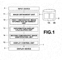
- FIG. 1 is a schematic diagram illustrating the configuration of a medical image display apparatus realized by installing a medical image display program in a workstation used by a doctor.
- a medical image display apparatus 1 includes, as the configuration of a standard workstation, a processor and a memory (both of which are not illustrated). Further, the medical image display apparatus 1 includes a storage 2, such as an HDD (Hard Disk Drive). Further, a display 3 and an input device 4, such as a mouse and a keyboard, are connected to the medical image display apparatus 1.
- the medical image display program and data referred to by the medical image display program are stored in the storage 2 at the time of installation, and loaded into the memory at boot-up.
- the medical image display program defines, as processing performed by a CPU, image obtainment processing, first tomographic image information obtainment processing, deformation amount calculation processing, second tomographic image identification processing and display control processing.
- a general-purpose workstation functions as an image obtainment unit 11, a first tomographic image information obtainment unit 12, a deformation amount calculation unit 13, a second tomographic image identification unit 14 and a display control unit 15, as will be described later.
- the storage 2 stores first image VA and second image VB transferred from an examination department in charge of imaging, or first image VA and second image VB retrieved from a database.
- first image VA and second image VB were obtained by imaging a same patient at first imaging time and at second imaging time, which was after the first imaging time, by a CT apparatus.
- Each of first image VA and second image VB was transferred from the examination department, and stored in the storage 2 to observe the course of the condition of the abdomen of a patient.
- Both of images VA, VB were obtained by imaging the same patient with the same posture to perform comparative image reading for analysis of a result of drug administration. It is assumed that the body axis of the patient and the direction of the body are substantially the same in the spatial coordinate systems of the two images.
- processing for unifying the scales of both of images VA, VB has been performed on one of images VA, VB based on pixel size (Pixel Spacing) and slice interval (Slice Spacing) obtained from arbitrary information, such as header information of both of images VA, VB, by using a known method.
- the image obtainment 11 obtains first image VA and second image VB from storage 2.
- the medical image display apparatus 1 detects selection of a predetermined comparative display function in a selection menu
- the medical image display apparatus 1 prompts a user to select or input information necessary to identify the first and second images.
- the image obtainment unit 11 loads first image VA and second image VB from the storage 2 into the memory.
- the first tomographic image information obtainment unit 12 obtains first tomographic image information, which identifies first tomographic image SA that is a slice image included in first image VA, and first region-of-interest information, which identifies a first region of interest on the first tomographic image.
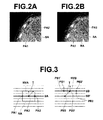
- Figure 2A and Figure 2B are diagrams of images for explaining a method for obtaining region-of-interest information. Both of the diagrams illustrate the same first tomographic image SA.
- First tomographic image SA represents xy cross section of first image VA, and is an axial image of the patient.
- a radiologist in charge of image reading sequentially displays tomographic images (axial images) included in first image VA, and determines an observation image representing a region of interest, as first tomographic image SA, by selection by a predetermined selection button, or the like. Then, the first tomographic image information obtainment unit 12 obtains the series name and the slice number of the first tomographic image, as information for identifying first tomographic image SA (first tomographic image information), and stores the information in the memory.
- the first tomographic image information obtainment unit 12 receives an input of the positions of two pixels PA1, PA2 on the boundary of first region of interest RA, such as an abnormal shadow region, on first tomographic image SA by an input operation by the user at the input device 4, and pixels PA1, PA2 face each other with the first region of interest therebetween. Accordingly, the first tomographic image information obtainment unit 12 obtains the coordinates of pixels PA1, PA2, which have been input at the input device 4. Further, as illustrated in Figure 2B , the first tomographic image information obtainment unit 12 obtains the first region of interest, as a rectangular parallelepiped region identified based on the obtained positions of pixels PA1, PA2.
- the first tomographic image information obtainment unit 12 obtains the coordinate of each vertex of a cube region that is first region of interest RA and information about the obtained coordinates of pixels PA1, PA2, as first region-of-interest identification information.
- the deformation amount calculation unit 13 deforms first image VA, and evaluates a degree of similarity between deformed first image VA and second image VB by using an evaluation function representing the degree of similarity between pixel values of deformed first image VA and corresponding pixel values of second image VB. Further, the deformation amount calculation unit 13 calculates a deformation amount (image deformation amount) of the first image to match the deformed first image and the second image match with each other.
- the deformation amount calculation unit 13 sets set X composed of control points x1, x2,...xn, which divide image space at predetermined intervals, in each of first image VA and second image VB.
- the set of control points x1, x2,...xn will be referred to as control point X.
- the deformation amount calculation unit 13 deforms first image VA by displacing control point X in first image VA by deformation amount ⁇ by known transformation function g. Control points to which control point X in first image VA is displaced by deformation amount ⁇ by transformation function g will be referred to as g(X, ⁇ ). Further, an image obtained by deforming first image VA by displacing control point X in first image VA by deformation amount ⁇ by transformation function g will be referred to as deformed first image VA'.
- the deformation amount calculation unit 13 obtains pixel value M(g(X, ⁇ )) at control point g(X, ⁇ ) in deformed first image VA'. Further, the deformation amount calculation unit 13 obtains pixel value F(X) at control point X in second image VB.
- the deformation amount calculation unit 13 determines deformation amount ⁇ of control point X when an evaluation function (registration function) representing the degree of similarity between pixel value M(g(X, ⁇ )) at each control point g(X, ⁇ ) in deformed first image VA' and pixel value F(X) at each control point X in second image VB is maximized.
- the deformation amount calculation unit 13 estimates a transformation function for first image VA based on deformation amount ⁇ of control point X of this time. In the evaluation function in the embodiment of the present invention, it is assumed that an evaluation value is larger as the degree of similarity is higher.
- the deformation amount calculation unit 13 may use a known non-rigid registration technique to calculate a deformation amount of the first image to match a subject in the first image and the subject in the second image with each other, and to estimate a transformation function based on the deformation amount.
- a non-rigid registration technique described in D. Mattes et al., "Nonrigid multimodality image registration", Proceedings of the SPIE, Vol. 4322, pp. 1609-1620, 2001 is used.
- the second tomographic image identification unit 14 identifies, based on image deformation amounts at plural positions included in first region of interest RA based on first region-of-interest information among the calculated image deformation amounts and first tomographic image information, a slice image in second image VB corresponding to first tomographic image SA, as second tomographic image SB. Further, the second tomographic image identification unit 14 identifies a region of interest in second image VB corresponding to first region of interest RA, as second region of interest RB.
- the second tomographic image identification unit 14 transforms first image VA by the transformation function estimated by the deformation amount calculation unit 13, and identifies corresponding pixels between first image VA and second image VB. Then, the second tomographic image identification unit 14 calculates, based on the first region-of-interest information, a deformation amount at each position in first region of interest RA to deform first image VA to match first image VA with second image VB. Next, the second tomographic image identification unit 14 obtains average value T (Tx, Ty, Tz) of deformation amounts at all pixels included in the first region of interest with respect to each of x, y and z directions in the three-dimensional coordinate system of first image VA.
- Figure 3 is a diagram for explaining a method for identifying a second tomographic image.
- the left-side section of Figure 3 is a diagram illustrating xz cross section of first image VA, and which shows first image VA in a direction perpendicular to Figures 2A, 2B .
- tomographic images constituting first image VA are indicated by horizontal lines
- first tomographic image SA is indicated by a bold horizontal line.
- the right-side section of Figure 3 is a diagram illustrating xz cross section of second image VB.
- plural tomographic images constituting second image VB are indicated by horizontal lines
- second tomographic image SB is indicated by a bold horizontal line.
- the second tomographic image identification unit 14 calculates the coordinate of pixel PA3, which is located at a middle point between PA1 and PA2 on first tomographic image SA. Further, the second tomographic image identification unit 14 obtains the coordinate of PB3', to which the position of pixel PB3 in second image VB having the same coordinate as PA3 is moved by average value T of deformation amounts of all pixels in first region of interest. Then, the second tomographic image identification unit 14 identifies an axial image including PB3' in second image VB, as second tomographic image SB.
- first tomographic image SA and second tomographic image SB are axial images (slice images representing a patient in a predetermined direction).
- an angle between normal vector NVA (an arrow indicated by a broken line in the left-side section of Figure 3 ) of first tomographic image SA and the body axis of the patient and an angle between normal vector NVB (an arrow indicated by a broken line in the right-side section of Figure 3 ) of second tomographic image SB and the body axis of the patient are equal.
- an axial image including PB3' in second image VB is generated by interpolating an axial image between two axial images next to each other in z direction with PB3' therebetween, and this generated image is used as second tomographic image SB.
- a plane including first tomographic image SA in the coordinate system of first image VB a plane located at the same position as the plane including first tomographic image SA may be identified in the coordinate system in second image VB.
- a plane obtained by moving this identified plane in the direction of z by average value Tz of movement amounts in z direction may be used as second tomographic image SB.
- the second tomographic image identification unit 14 identifies a region composed of pixels in second image VB corresponding to all pixels included in first region of interest RA, as second region-of-interest region RB. Further, the second tomographic image identification unit calculates coordinates on second tomographic image onto which the coordinates of pixels located on the outline of second region of interest RB are projected perpendicularly.
- PB1 and PB2 in second image VB illustrated in the right-side section of Figure 3 , are pixels corresponding to PA1 and PA2 in first tomographic image SA, respectively.
- PA1 and PA2 are included in first tomographic image SA in first image VA.
- both of PB1 and PB2 are located at positions that are not included in second tomographic image SB because of temporal change, a slight difference in the posture of the patient during imaging or the like.
- the display control unit 15 makes first tomographic image SA and second tomographic image SB displayed on display 3 in such a manner to be comparable with each other. Further, the display control unit 15 projects second region of interest RB onto second tomographic image SB, and makes second region of interest RB distinguishably displayed.
- the display control unit 15 may make obtained first image VA and second image VB and/or each image generated during execution of the medical image display program according to the embodiment of the present invention on the display 3, if necessary for an input by a user, or the like.
- Figure 4 is a diagram illustrating an example of comparative display of first tomographic image SA and second tomographic image SB.
- the display control unit 15 distinguishably displays the outline of second region of interest RB projected onto second tomographic image SB by using white index MA.
- the display control unit 15 distinguishably displays first region of interest RA and two pixels PA1, PA2, which have been specified on the boundary of first region of interest RA by an operation by a user, on first tomographic image SA.
- the display control unit 15 distinguishably displays pixels PB1', PB2' at positions on second tomographic image SB onto which the positions of pixels PB1, PB2 corresponding to two pixels PA1, PA2 are projected.
- Figure 5 is a flow chart illustrating a desirable embodiment of a medical image display method of the present invention. Medical image display according to embodiments of the present invention will be described with reference to Figure 5 .
- the image obtainment unit 11 obtains first image (first image data) VA and second image (second image data) VB obtained by imaging a subject (S01).
- the first tomographic image information obtainment unit 12 obtains information for identifying first tomographic image SA and information for identifying first region of interest RA included in first tomographic image SA (S02) .
- the deformation amount calculation unit 13 calculates deformation amount ⁇ to maximize the evaluation function based on the evaluation function representing the degree of similarity between pixel values of first image VA and pixel values of second image VB. Further, the deformation amount calculation unit 13 estimates, based on the calculated deformation amount, a transformation function to match the pixel values of first image VA and second image VB with each other (S03).
- the second tomographic image identification unit 14 identifies, based on image deformations amounts at plural positions in first region of interest RA, second tomographic image SB and second region of interest RB (S04). Then, as illustrated in Figure 4 , the display control unit 15 displays first tomographic image SA and second tomographic image SB next to each other in such a manner to be comparable with each other. Further, the display control unit 15 distinguishably displays a region of interest on second tomographic image SB by using index MB of an outline (S05).
- the second tomographic image identification unit identifies, based on deformation amounts at plural positions included in first region of interest RA, corresponding second tomographic image SB.
- a lesion or the like which spreads to some extent, is often used as a region of interest. Therefore, when the position of the second tomographic image is identified by using information about deformation amounts at plural positions in the first region of interest, it is possible to appropriately identify the position of the second tomographic image SB corresponding to the first tomographic image SA by using the deformation amounts at plural positions in the first region of interest for judgment, and to display the images for comparison. Consequently, it is possible to assist accurate comparative image reading.
- corresponding second tomographic image SB was identified based on deformation amounts at all positions included in first region of interest RA. Therefore, the aforementioned effects are more remarkably achievable.
- the present invention is not limited to the embodiment of the present invention.
- Corresponding second tomographic image SB may be identified based on a deformation amount or amounts at a part of positions included in first region of interest RA.
- Patent Documents 1 through 4 a deformed image of one of images is generated, and displayed.
- tomographic images at corresponding positions at two points in time, and which are not deformed are displayed in such a manner to be comparable to observe the course of the condition of a patient. Therefore, it is possible to display a tomographic image satisfying a demand for performing comparative image reading by displaying the tomographic image without deforming the tomographic image so as to accurately observe the real shape of an organ and a region of interest in the practice of diagnosis. Further, it is possible to save the cost of processing for generating a deformed image, which is required in the methods disclosed in Patent Documents 1 through 4.
- the second tomographic image identification unit 14 identifies second tomographic image in such a manner that an angle between second tomographic image SB and a body axis of the patient and an angle between first tomographic image SA and the body axis of the patient are equal, and also that the second tomographic image includes at least one position to which at least one position in the second image that has the same coordinate or coordinates as the coordinate or coordinates of at least one point in the first tomographic image is moved by a mean value of image deformation amounts at plural positions included in the first region of interest. Therefore, the inclination of a slice plane represented by the first tomographic image and the inclination of a slice plane represented by the second tomographic image appropriately correspond to each other.
- the first tomographic image and the second tomographic image are axial images used in the current practice of observation of the course of the condition of a patient. Therefore, those in medical fields can easily observe the images, and it is possible to effectively improve the efficiency in image reading.
- the second tomographic image identification unit 14 may identify the second tomographic image by using any method as long as the second tomographic image is identified in such a manner that an angle between second tomographic image SB and a body axis of the patient and an angle between first tomographic image SA and the body axis of the patient are equal, and also that the second tomographic image includes at least one position to which at least one position in the second image that has the same coordinate or coordinates as the coordinate or coordinates of at least one point in the first tomographic image is moved by an average value of image deformation amounts at plural positions included in the first region of interest.
- the position of pixel PA3 located at a middle point between positions PA1, PA2 in the first tomographic image, which have been specified by the user, is associated with the position of pixel PB3' on second tomographic image SB, and second tomographic image SB is identified based on this PA3'.
- the present invention is not limited to this embodiment.
- a pair of a position in the first tomographic image and a position corresponding to this position in the second tomographic image may be arbitrarily determined.
- the second tomographic image appropriately includes a position in the region of interest.
- the second tomographic image is highly likely to more appropriately represent the region of interest.
- second tomographic image SB and the second region of interest are displayed for comparison only by specifying the region of interest in one of the images. Therefore, it is possible to reduce the burden on the user in operations, compared with a conventional case in which tomographic images for comparative image reading are extracted from first and second image VA, VB by manual operations by the user, and corresponding regions of interest are set on the extracted tomographic images also by manual operations by the user.
- first region of interest RA is a rectangular parallelepiped region, which is a predetermined polyhedral region, defined based on the positions of plural pixels PA1, PA2 on the boundary of the first region of interest. Therefore, an operation for inputting the first region of interest by the user is easy.
- a polyhedral region in arbitrary shape such as a sphere and a cube, may be adopted as the predetermined polyhedral region.
- an arbitrary method may be used as a method for specifying the predetermined polyhedral region by the operations by the user.
- first region of interest RA is identified based on the positions of two pixels PA1, PA2 on the boundary of the first region of interest facing each other with the first region of interest therebetween, the operation of inputting the first region of interest by the user is easy.
- the present invention is not limited to the embodiment of the present invention.
- the first region of interest may be a two-dimensional region on the first tomographic image. Further, the first region of interest may be composed of a curved surface. Alternatively, the first region of interest may be composed of a combination of a curved surface and a flat surface. Further, the first region of interest may be a region obtained by recognizing the region by using a known image recognition technique instead of the region obtained by receiving an operation by the user at the input device.
- the display control unit 15 projects only the outline of second region of interest RB onto second tomographic image SB, and distinguishably displays index MB of the projected outline on second tomographic image SB, it is possible to easily recognize second region of interest SB.
- the user can use the size of the displayed index to obtain information usable as a guide for measurement.
- the user may use the size of the rectangular index in the embodiment of the present invention, as a target of the size of the region of interest.
- the user may use the length of a diagonal line connecting PA1 and PA2 in the rectangular index in the embodiment of the present invention, as the target of the diameter of the region of interest.
- Second region of interest RB may be displayed by using a known method as long as second region of interest RB is projected onto second tomographic image SB, and distinguishably displayed.
- a projection image of second region of interest RB may be displayed as a semitransparent image.
- the outline of second region of interest RB is projected onto second tomographic image SB and distinguishably displayed, and the outline of first region of interest RA is also displayed on first tomographic image SA, it is possible to easily compare the regions of interest with each other. Therefore, it is possible to improve the efficiency of image reading.
- the positions of two pixels PA1, PA2 specified on the boundary of the region of interest by an operation by the user, and which face each other with the region of interest therebetween, are displayed on first tomographic image SA. Further, pixels PB1', PB2' on second tomographic image SB, onto which PA1, PA2 are projected, and which are at positions corresponding to PA1, PA2, are displayed on second tomographic image SB. Therefore, comparison between the regions of interest is easier.
- first region-of-interest information may be information representing plural positions on the boundary of the first region of interest.
- the second tomographic image identification unit 14 may calculate the image deformation amount of the first region of interest by obtaining a weighted average of image deformation amounts corresponding to positions included in the first region of interest by increasing weighting as distances from the plural positions on the boundary of the first region of interest to each of the positions are shorter.
- the movement amount (a weighted average of deformation amounts) of the second tomographic image with respect to the first tomographic image may be calculated, based on the position of a region that has been discriminated as a region of interest by the user and deformation amounts in the vicinity of this position, by using the weighted average of deformation amounts obtained by increasing weighting on deformation amounts on the boundary of the region of interest. Therefore, it is possible to appropriately identify and display the second tomographic image located at a position corresponding to the user' s region of interest and a deformation amount of the discriminated position.
- corresponding pixels between first image VA and second image VB may be determined by estimating a transformation function of first image VA based on the image deformation amount for deforming first image VA to match first image VA and second image VB with each other, and by transforming first image VA by using the estimated transformation function.
- corresponding pixels between first image VA and second image VB may be determined by estimating a transformation function of second image VB based on the image deformation amount for deforming second image VB to match first image VA and second image VB with each other, and by transforming second image VB by using the estimated transformation function.
- a known non-rigid registration technique may be adopted as a non-rigid registration technique for matching first image VA and second image VB with each other.
- either deformation amount calculation processing or first region-of-interest obtainment processing may be performed first, or they may be performed at the same time.
- system configuration the hardware configuration, the flow of processing, the module configuration, user interface, the specific contents of processing and the like may be modified in various manners without departing from the spirit of the present invention, and such modifications are still within the technical scope of the present invention.
- the medical image display apparatus 1 may be configured by making plural computers share functions as means.
- apparatuses constituting the system such as the input device and display, any known apparatus may be adopted.
Landscapes
- Engineering & Computer Science (AREA)
- Physics & Mathematics (AREA)
- Health & Medical Sciences (AREA)
- General Physics & Mathematics (AREA)
- Theoretical Computer Science (AREA)
- Life Sciences & Earth Sciences (AREA)
- Medical Informatics (AREA)
- General Health & Medical Sciences (AREA)
- Radiology & Medical Imaging (AREA)
- Nuclear Medicine, Radiotherapy & Molecular Imaging (AREA)
- Computer Vision & Pattern Recognition (AREA)
- Biomedical Technology (AREA)
- Public Health (AREA)
- Veterinary Medicine (AREA)
- Pathology (AREA)
- Heart & Thoracic Surgery (AREA)
- Molecular Biology (AREA)
- Surgery (AREA)
- Animal Behavior & Ethology (AREA)
- Biophysics (AREA)
- Quality & Reliability (AREA)
- High Energy & Nuclear Physics (AREA)
- Optics & Photonics (AREA)
- Human Computer Interaction (AREA)
- Architecture (AREA)
- Computer Graphics (AREA)
- Computer Hardware Design (AREA)
- General Engineering & Computer Science (AREA)
- Software Systems (AREA)
- Apparatus For Radiation Diagnosis (AREA)
Applications Claiming Priority (2)
| Application Number | Priority Date | Filing Date | Title |
|---|---|---|---|
| JP2012047538A JP5745444B2 (ja) | 2012-03-05 | 2012-03-05 | 医用画像表示装置および医用画像表示方法、並びに、医用画像表示プログラム |
| PCT/JP2013/001234 WO2013132801A1 (fr) | 2012-03-05 | 2013-02-28 | Dispositif d'affichage d'images médicales et procédé d'affichage d'images médicales ainsi que programme d'affichage d'images médicales |
Publications (3)
| Publication Number | Publication Date |
|---|---|
| EP2823765A1 true EP2823765A1 (fr) | 2015-01-14 |
| EP2823765A4 EP2823765A4 (fr) | 2015-11-11 |
| EP2823765B1 EP2823765B1 (fr) | 2017-02-01 |
Family
ID=49116297
Family Applications (1)
| Application Number | Title | Priority Date | Filing Date |
|---|---|---|---|
| EP13758049.4A Active EP2823765B1 (fr) | 2012-03-05 | 2013-02-28 | Dispositif d'affichage d'images médicales et procédé d'affichage d'images médicales ainsi que programme d'affichage d'images médicales |
Country Status (4)
| Country | Link |
|---|---|
| US (1) | US9119599B2 (fr) |
| EP (1) | EP2823765B1 (fr) |
| JP (1) | JP5745444B2 (fr) |
| WO (1) | WO2013132801A1 (fr) |
Cited By (19)
| Publication number | Priority date | Publication date | Assignee | Title |
|---|---|---|---|---|
| US11403483B2 (en) | 2017-06-20 | 2022-08-02 | Hologic, Inc. | Dynamic self-learning medical image method and system |
| US11406332B2 (en) | 2011-03-08 | 2022-08-09 | Hologic, Inc. | System and method for dual energy and/or contrast enhanced breast imaging for screening, diagnosis and biopsy |
| US11419565B2 (en) | 2014-02-28 | 2022-08-23 | IIologic, Inc. | System and method for generating and displaying tomosynthesis image slabs |
| US11445993B2 (en) | 2017-03-30 | 2022-09-20 | Hologic, Inc. | System and method for targeted object enhancement to generate synthetic breast tissue images |
| US11455754B2 (en) | 2017-03-30 | 2022-09-27 | Hologic, Inc. | System and method for synthesizing low-dimensional image data from high-dimensional image data using an object grid enhancement |
| US11452486B2 (en) | 2006-02-15 | 2022-09-27 | Hologic, Inc. | Breast biopsy and needle localization using tomosynthesis systems |
| US11508340B2 (en) | 2011-11-27 | 2022-11-22 | Hologic, Inc. | System and method for generating a 2D image using mammography and/or tomosynthesis image data |
| US11589944B2 (en) | 2013-03-15 | 2023-02-28 | Hologic, Inc. | Tomosynthesis-guided biopsy apparatus and method |
| US11663780B2 (en) | 2012-02-13 | 2023-05-30 | Hologic Inc. | System and method for navigating a tomosynthesis stack using synthesized image data |
| US11701199B2 (en) | 2009-10-08 | 2023-07-18 | Hologic, Inc. | Needle breast biopsy system and method of use |
| US11775156B2 (en) | 2010-11-26 | 2023-10-03 | Hologic, Inc. | User interface for medical image review workstation |
| US11957497B2 (en) | 2017-03-30 | 2024-04-16 | Hologic, Inc | System and method for hierarchical multi-level feature image synthesis and representation |
| US12029602B2 (en) | 2013-10-24 | 2024-07-09 | Hologic, Inc. | System and method for navigating x-ray guided breast biopsy |
| US12211608B2 (en) | 2013-03-15 | 2025-01-28 | Hologic, Inc. | System and method for navigating a tomosynthesis stack including automatic focusing |
| US12236582B2 (en) | 2018-09-24 | 2025-02-25 | Hologic, Inc. | Breast mapping and abnormality localization |
| US12236597B2 (en) | 2021-11-29 | 2025-02-25 | Hologic, Inc. | Systems and methods for correlating objects of interest |
| US12254586B2 (en) | 2021-10-25 | 2025-03-18 | Hologic, Inc. | Auto-focus tool for multimodality image review |
| US12507980B2 (en) | 2020-03-27 | 2025-12-30 | Hologic, Inc. | Systems and methods for identifying regions of interest in multiple imaging modalities |
| US12530860B2 (en) | 2020-11-20 | 2026-01-20 | Hologic, Inc. | Systems and methods for using AI to identify regions of interest in medical images |
Families Citing this family (19)
| Publication number | Priority date | Publication date | Assignee | Title |
|---|---|---|---|---|
| WO2013111813A1 (fr) * | 2012-01-27 | 2013-08-01 | 株式会社 東芝 | Dispositif médical de traitement d'image |
| EP2648160B1 (fr) * | 2012-04-03 | 2017-03-08 | Intrasense | Procédé de remappage de ROI à préservation de topologie entre des images médicales |
| JP6026932B2 (ja) * | 2013-03-22 | 2016-11-16 | 富士フイルム株式会社 | 医用画像表示制御装置および方法並びにプログラム |
| KR102244258B1 (ko) | 2013-10-04 | 2021-04-27 | 삼성전자주식회사 | 디스플레이 장치 및 이를 이용한 영상표시방법 |
| JP6128691B2 (ja) * | 2014-07-10 | 2017-05-17 | 富士フイルム株式会社 | 医用画像計測装置および方法並びにプログラム |
| JP6528386B2 (ja) * | 2014-11-04 | 2019-06-12 | 富士通株式会社 | 画像処理装置、画像処理方法及び画像処理プログラム |
| WO2016078958A1 (fr) * | 2014-11-20 | 2016-05-26 | Koninklijke Philips N.V. | Procédé pour la génération de clichés de mammographie synthétiques à partir de données de tomosynthèse |
| US10437157B2 (en) | 2014-12-09 | 2019-10-08 | Asml Netherlands B.V. | Method and apparatus for image analysis |
| WO2016091536A1 (fr) * | 2014-12-09 | 2016-06-16 | Asml Netherlands B.V. | Procédé et appareil d'analyse d'images |
| JP6840481B2 (ja) * | 2016-07-19 | 2021-03-10 | キヤノン株式会社 | 画像処理装置および画像処理方法 |
| JP6934734B2 (ja) * | 2017-03-17 | 2021-09-15 | キヤノン株式会社 | 画像処理装置、画像処理装置の制御方法およびプログラム |
| CN107545564A (zh) * | 2017-07-20 | 2018-01-05 | 广东工业大学 | 电网输电线路绝缘子伞裙缺陷检测方法 |
| JP7237454B2 (ja) * | 2018-04-12 | 2023-03-13 | キヤノン株式会社 | 画像処理装置、画像処理装置の制御方法、及びプログラム |
| CN114745985B (zh) | 2019-10-03 | 2025-10-17 | 康奈尔大学 | 根据乳房的3d形状优化文胸尺寸确定 |
| EP3832602A1 (fr) * | 2019-12-03 | 2021-06-09 | Koninklijke Philips N.V. | Appareil, procédé et programme informatique pour surveiller un sujet pendant une procédure d'imagerie médicale |
| JP7323128B2 (ja) * | 2020-03-12 | 2023-08-08 | 東芝エネルギーシステムズ株式会社 | 医用画像処理装置、医用装置、治療システム、医用画像処理方法、およびプログラム |
| US12505645B2 (en) | 2020-03-27 | 2025-12-23 | Hologic, Inc. | Systems and methods for correlating regions of interest in multiple imaging modalities |
| CN113469972B (zh) * | 2021-06-30 | 2024-04-23 | 沈阳东软智能医疗科技研究院有限公司 | 标注医学切片图像的方法、装置、存储介质及电子设备 |
| CN116580071A (zh) * | 2022-01-29 | 2023-08-11 | 佳能医疗系统株式会社 | 医用图像配准方法、医用图像处理装置、存储介质及程序产品 |
Family Cites Families (16)
| Publication number | Priority date | Publication date | Assignee | Title |
|---|---|---|---|---|
| JPH10137231A (ja) * | 1996-11-13 | 1998-05-26 | Toshiba Iyou Syst Eng Kk | 医用画像処理装置 |
| US7903849B2 (en) | 2005-04-15 | 2011-03-08 | Kabushiki Kaisha Toshiba | Medical image processing apparatus |
| JP5366356B2 (ja) * | 2005-04-15 | 2013-12-11 | 株式会社東芝 | 医用画像処理装置及び医用画像処理方法 |
| JP5100041B2 (ja) * | 2005-06-15 | 2012-12-19 | 株式会社東芝 | 画像処理装置及び画像処理プログラム |
| US7676072B2 (en) * | 2005-06-15 | 2010-03-09 | Kabushiki Kaisha Toshiba | Image processing apparatus and image processing method |
| JP2009522005A (ja) | 2005-12-29 | 2009-06-11 | ケアストリーム ヘルス インク | 時間横断的かつモダリティ横断的な医療診断 |
| JP5072449B2 (ja) * | 2006-07-18 | 2012-11-14 | 株式会社東芝 | 医用画像処理装置及び医用画像処理方法 |
| EP1881453A3 (fr) | 2006-07-18 | 2009-07-22 | Kabushiki Kaisha Toshiba | Appareil de traitement d'images médicales et procédé pour le traitement d'images médicales |
| JP2008086400A (ja) | 2006-09-29 | 2008-04-17 | Gifu Univ | 乳房画像診断システム |
| JP5159301B2 (ja) * | 2007-12-28 | 2013-03-06 | 株式会社東芝 | 医用画像表示装置および画像表示方法 |
| JP5279291B2 (ja) | 2008-02-19 | 2013-09-04 | 株式会社東芝 | 医用画像表示装置および画像表示方法 |
| EP2098991A1 (fr) * | 2008-03-06 | 2009-09-09 | Agfa HealthCare NV | Procédé de recalage et d'affichage d'images médicales |
| JP5437610B2 (ja) * | 2008-09-01 | 2014-03-12 | 株式会社日立メディコ | 磁気共鳴イメージング装置 |
| JP2011024763A (ja) * | 2009-07-24 | 2011-02-10 | Hitachi Ltd | 画像処理方法および画像処理装置 |
| JP5090486B2 (ja) | 2009-09-30 | 2012-12-05 | 富士フイルム株式会社 | 肝臓造影像を用いた医用画像診断装置および画像表示方法、並びにプログラム |
| US8452126B2 (en) * | 2011-06-17 | 2013-05-28 | General Electric Company | Method for automatic mismatch correction of image volumes |
-
2012
- 2012-03-05 JP JP2012047538A patent/JP5745444B2/ja active Active
-
2013
- 2013-02-28 WO PCT/JP2013/001234 patent/WO2013132801A1/fr not_active Ceased
- 2013-02-28 EP EP13758049.4A patent/EP2823765B1/fr active Active
-
2014
- 2014-09-03 US US14/476,487 patent/US9119599B2/en active Active
Cited By (35)
| Publication number | Priority date | Publication date | Assignee | Title |
|---|---|---|---|---|
| US12193853B2 (en) | 2006-02-15 | 2025-01-14 | Hologic, Inc. | Breast biopsy and needle localization using tomosynthesis systems |
| US11452486B2 (en) | 2006-02-15 | 2022-09-27 | Hologic, Inc. | Breast biopsy and needle localization using tomosynthesis systems |
| US11918389B2 (en) | 2006-02-15 | 2024-03-05 | Hologic, Inc. | Breast biopsy and needle localization using tomosynthesis systems |
| US12193886B2 (en) | 2009-10-08 | 2025-01-14 | Hologic, Inc. | Needle breast biopsy system and method of use |
| US11701199B2 (en) | 2009-10-08 | 2023-07-18 | Hologic, Inc. | Needle breast biopsy system and method of use |
| US11775156B2 (en) | 2010-11-26 | 2023-10-03 | Hologic, Inc. | User interface for medical image review workstation |
| US12239471B2 (en) | 2011-03-08 | 2025-03-04 | Hologic, Inc. | System and method for dual energy and/or contrast enhanced breast imaging for screening, diagnosis and biopsy |
| US11406332B2 (en) | 2011-03-08 | 2022-08-09 | Hologic, Inc. | System and method for dual energy and/or contrast enhanced breast imaging for screening, diagnosis and biopsy |
| US12183309B2 (en) | 2011-11-27 | 2024-12-31 | Hologic, Inc. | System and method for generating a 2D image using mammography and/or tomosynthesis image data |
| US11508340B2 (en) | 2011-11-27 | 2022-11-22 | Hologic, Inc. | System and method for generating a 2D image using mammography and/or tomosynthesis image data |
| US11837197B2 (en) | 2011-11-27 | 2023-12-05 | Hologic, Inc. | System and method for generating a 2D image using mammography and/or tomosynthesis image data |
| US12307604B2 (en) | 2012-02-13 | 2025-05-20 | Hologic, Inc. | System and method for navigating a tomosynthesis stack using synthesized image data |
| US11663780B2 (en) | 2012-02-13 | 2023-05-30 | Hologic Inc. | System and method for navigating a tomosynthesis stack using synthesized image data |
| US11589944B2 (en) | 2013-03-15 | 2023-02-28 | Hologic, Inc. | Tomosynthesis-guided biopsy apparatus and method |
| US12211608B2 (en) | 2013-03-15 | 2025-01-28 | Hologic, Inc. | System and method for navigating a tomosynthesis stack including automatic focusing |
| US12324707B2 (en) | 2013-03-15 | 2025-06-10 | Hologic, Inc. | Tomosynthesis-guided biopsy in prone |
| US12475992B2 (en) | 2013-03-15 | 2025-11-18 | Hologic, Inc. | System and method for navigating a tomosynthesis stack including automatic focusing |
| US12064291B2 (en) | 2013-03-15 | 2024-08-20 | Hologic, Inc. | Tomosynthesis-guided biopsy in prone |
| US12029602B2 (en) | 2013-10-24 | 2024-07-09 | Hologic, Inc. | System and method for navigating x-ray guided breast biopsy |
| US11801025B2 (en) | 2014-02-28 | 2023-10-31 | Hologic, Inc. | System and method for generating and displaying tomosynthesis image slabs |
| US12564365B2 (en) | 2014-02-28 | 2026-03-03 | Hologic, Inc. | System and method for generating and displaying tomosynthesis image slabs |
| US11419565B2 (en) | 2014-02-28 | 2022-08-23 | IIologic, Inc. | System and method for generating and displaying tomosynthesis image slabs |
| US12211124B2 (en) | 2017-03-30 | 2025-01-28 | Hologic, Inc. | System and method for synthesizing low-dimensional image data from high-dimensional image data using an object grid enhancement |
| US12070349B2 (en) | 2017-03-30 | 2024-08-27 | Hologic, Inc. | System and method for targeted object enhancement to generate synthetic breast tissue images |
| US11957497B2 (en) | 2017-03-30 | 2024-04-16 | Hologic, Inc | System and method for hierarchical multi-level feature image synthesis and representation |
| US11455754B2 (en) | 2017-03-30 | 2022-09-27 | Hologic, Inc. | System and method for synthesizing low-dimensional image data from high-dimensional image data using an object grid enhancement |
| US11445993B2 (en) | 2017-03-30 | 2022-09-20 | Hologic, Inc. | System and method for targeted object enhancement to generate synthetic breast tissue images |
| US12446842B2 (en) | 2017-03-30 | 2025-10-21 | Hologic, Inc. | System and method for hierarchical multi-level feature image synthesis and representation |
| US11983799B2 (en) | 2017-03-30 | 2024-05-14 | Hologic, Inc. | System and method for synthesizing low-dimensional image data from high-dimensional image data using an object grid enhancement |
| US11403483B2 (en) | 2017-06-20 | 2022-08-02 | Hologic, Inc. | Dynamic self-learning medical image method and system |
| US12236582B2 (en) | 2018-09-24 | 2025-02-25 | Hologic, Inc. | Breast mapping and abnormality localization |
| US12507980B2 (en) | 2020-03-27 | 2025-12-30 | Hologic, Inc. | Systems and methods for identifying regions of interest in multiple imaging modalities |
| US12530860B2 (en) | 2020-11-20 | 2026-01-20 | Hologic, Inc. | Systems and methods for using AI to identify regions of interest in medical images |
| US12254586B2 (en) | 2021-10-25 | 2025-03-18 | Hologic, Inc. | Auto-focus tool for multimodality image review |
| US12236597B2 (en) | 2021-11-29 | 2025-02-25 | Hologic, Inc. | Systems and methods for correlating objects of interest |
Also Published As
| Publication number | Publication date |
|---|---|
| WO2013132801A1 (fr) | 2013-09-12 |
| JP2013180153A (ja) | 2013-09-12 |
| EP2823765A4 (fr) | 2015-11-11 |
| US20150002547A1 (en) | 2015-01-01 |
| JP5745444B2 (ja) | 2015-07-08 |
| EP2823765B1 (fr) | 2017-02-01 |
| US9119599B2 (en) | 2015-09-01 |
Similar Documents
| Publication | Publication Date | Title |
|---|---|---|
| EP2823765B1 (fr) | Dispositif d'affichage d'images médicales et procédé d'affichage d'images médicales ainsi que programme d'affichage d'images médicales | |
| US9035941B2 (en) | Image processing apparatus and image processing method | |
| US9965857B2 (en) | Medical image processing | |
| US10417517B2 (en) | Medical image correlation apparatus, method and storage medium | |
| JP5737858B2 (ja) | 画像処理装置、画像処理方法、及びプログラム | |
| US9058647B2 (en) | Information processing apparatus, information processing method, and storage medium | |
| US8908944B2 (en) | Information processing apparatus, information processing method, and program | |
| US20180092537A1 (en) | Information processing apparatus | |
| US9953423B2 (en) | Image processing apparatus, image processing method, and storage medium for image processing based on priority | |
| US8363918B2 (en) | Method and system for anatomic landmark detection using constrained marginal space learning and geometric inference | |
| US20130044927A1 (en) | Image processing method and system | |
| JP5706389B2 (ja) | 画像処理装置および画像処理方法、並びに、画像処理プログラム | |
| JP6541334B2 (ja) | 画像処理装置、画像処理方法、およびプログラム | |
| US9576361B2 (en) | Image processing apparatus and image processing method | |
| US10762648B2 (en) | Image processing apparatus, image processing method, image processing system, and program | |
| US20120027277A1 (en) | Interactive iterative closest point algorithm for organ segmentation | |
| EP4156089A1 (fr) | Procédé, dispositif et système de traitement automatisé d'images médicales permettant de générer des alertes pour des dissimilarités détectées | |
| EP4505398B1 (fr) | Détection automatique de fracture de côtes à partir d'images d'acquisition dépliées | |
| JP6660741B2 (ja) | 画像抽出装置、画像抽出方法 | |
| US10929990B2 (en) | Registration apparatus, method, and program | |
| CN115082373A (zh) | 医学影像定位线的测试方法、装置、设备及存储介质 | |
| EP4258207A1 (fr) | Détection automatique de fracture de côtes à partir d'images d'acquisition dépliées | |
| WO2017130263A1 (fr) | Appareil de traitement d'images, procédé de traitement d'images, système de traitement d'images, et programme |
Legal Events
| Date | Code | Title | Description |
|---|---|---|---|
| PUAI | Public reference made under article 153(3) epc to a published international application that has entered the european phase |
Free format text: ORIGINAL CODE: 0009012 |
|
| 17P | Request for examination filed |
Effective date: 20140929 |
|
| AK | Designated contracting states |
Kind code of ref document: A1 Designated state(s): AL AT BE BG CH CY CZ DE DK EE ES FI FR GB GR HR HU IE IS IT LI LT LU LV MC MK MT NL NO PL PT RO RS SE SI SK SM TR |
|
| AX | Request for extension of the european patent |
Extension state: BA ME |
|
| DAX | Request for extension of the european patent (deleted) | ||
| RA4 | Supplementary search report drawn up and despatched (corrected) |
Effective date: 20151013 |
|
| RIC1 | Information provided on ipc code assigned before grant |
Ipc: G06T 7/00 20060101ALI20151007BHEP Ipc: A61B 6/03 20060101AFI20151007BHEP |
|
| GRAP | Despatch of communication of intention to grant a patent |
Free format text: ORIGINAL CODE: EPIDOSNIGR1 |
|
| INTG | Intention to grant announced |
Effective date: 20160916 |
|
| GRAS | Grant fee paid |
Free format text: ORIGINAL CODE: EPIDOSNIGR3 |
|
| STAA | Information on the status of an ep patent application or granted ep patent |
Free format text: STATUS: GRANT OF PATENT IS INTENDED |
|
| GRAA | (expected) grant |
Free format text: ORIGINAL CODE: 0009210 |
|
| STAA | Information on the status of an ep patent application or granted ep patent |
Free format text: STATUS: THE PATENT HAS BEEN GRANTED |
|
| AK | Designated contracting states |
Kind code of ref document: B1 Designated state(s): AL AT BE BG CH CY CZ DE DK EE ES FI FR GB GR HR HU IE IS IT LI LT LU LV MC MK MT NL NO PL PT RO RS SE SI SK SM TR |
|
| REG | Reference to a national code |
Ref country code: GB Ref legal event code: FG4D |
|
| REG | Reference to a national code |
Ref country code: CH Ref legal event code: EP Ref country code: AT Ref legal event code: REF Ref document number: 864870 Country of ref document: AT Kind code of ref document: T Effective date: 20170215 |
|
| REG | Reference to a national code |
Ref country code: IE Ref legal event code: FG4D |
|
| REG | Reference to a national code |
Ref country code: DE Ref legal event code: R096 Ref document number: 602013017057 Country of ref document: DE |
|
| REG | Reference to a national code |
Ref country code: NL Ref legal event code: MP Effective date: 20170201 |
|
| REG | Reference to a national code |
Ref country code: LT Ref legal event code: MG4D |
|
| REG | Reference to a national code |
Ref country code: AT Ref legal event code: MK05 Ref document number: 864870 Country of ref document: AT Kind code of ref document: T Effective date: 20170201 |
|
| PG25 | Lapsed in a contracting state [announced via postgrant information from national office to epo] |
Ref country code: GR Free format text: LAPSE BECAUSE OF FAILURE TO SUBMIT A TRANSLATION OF THE DESCRIPTION OR TO PAY THE FEE WITHIN THE PRESCRIBED TIME-LIMIT Effective date: 20170502 Ref country code: NO Free format text: LAPSE BECAUSE OF FAILURE TO SUBMIT A TRANSLATION OF THE DESCRIPTION OR TO PAY THE FEE WITHIN THE PRESCRIBED TIME-LIMIT Effective date: 20170501 Ref country code: FI Free format text: LAPSE BECAUSE OF FAILURE TO SUBMIT A TRANSLATION OF THE DESCRIPTION OR TO PAY THE FEE WITHIN THE PRESCRIBED TIME-LIMIT Effective date: 20170201 Ref country code: LT Free format text: LAPSE BECAUSE OF FAILURE TO SUBMIT A TRANSLATION OF THE DESCRIPTION OR TO PAY THE FEE WITHIN THE PRESCRIBED TIME-LIMIT Effective date: 20170201 Ref country code: HR Free format text: LAPSE BECAUSE OF FAILURE TO SUBMIT A TRANSLATION OF THE DESCRIPTION OR TO PAY THE FEE WITHIN THE PRESCRIBED TIME-LIMIT Effective date: 20170201 Ref country code: IS Free format text: LAPSE BECAUSE OF FAILURE TO SUBMIT A TRANSLATION OF THE DESCRIPTION OR TO PAY THE FEE WITHIN THE PRESCRIBED TIME-LIMIT Effective date: 20170601 |
|
| PG25 | Lapsed in a contracting state [announced via postgrant information from national office to epo] |
Ref country code: ES Free format text: LAPSE BECAUSE OF FAILURE TO SUBMIT A TRANSLATION OF THE DESCRIPTION OR TO PAY THE FEE WITHIN THE PRESCRIBED TIME-LIMIT Effective date: 20170201 Ref country code: LV Free format text: LAPSE BECAUSE OF FAILURE TO SUBMIT A TRANSLATION OF THE DESCRIPTION OR TO PAY THE FEE WITHIN THE PRESCRIBED TIME-LIMIT Effective date: 20170201 Ref country code: SE Free format text: LAPSE BECAUSE OF FAILURE TO SUBMIT A TRANSLATION OF THE DESCRIPTION OR TO PAY THE FEE WITHIN THE PRESCRIBED TIME-LIMIT Effective date: 20170201 Ref country code: PT Free format text: LAPSE BECAUSE OF FAILURE TO SUBMIT A TRANSLATION OF THE DESCRIPTION OR TO PAY THE FEE WITHIN THE PRESCRIBED TIME-LIMIT Effective date: 20170601 Ref country code: RS Free format text: LAPSE BECAUSE OF FAILURE TO SUBMIT A TRANSLATION OF THE DESCRIPTION OR TO PAY THE FEE WITHIN THE PRESCRIBED TIME-LIMIT Effective date: 20170201 Ref country code: AT Free format text: LAPSE BECAUSE OF FAILURE TO SUBMIT A TRANSLATION OF THE DESCRIPTION OR TO PAY THE FEE WITHIN THE PRESCRIBED TIME-LIMIT Effective date: 20170201 Ref country code: BG Free format text: LAPSE BECAUSE OF FAILURE TO SUBMIT A TRANSLATION OF THE DESCRIPTION OR TO PAY THE FEE WITHIN THE PRESCRIBED TIME-LIMIT Effective date: 20170501 Ref country code: PL Free format text: LAPSE BECAUSE OF FAILURE TO SUBMIT A TRANSLATION OF THE DESCRIPTION OR TO PAY THE FEE WITHIN THE PRESCRIBED TIME-LIMIT Effective date: 20170201 Ref country code: NL Free format text: LAPSE BECAUSE OF FAILURE TO SUBMIT A TRANSLATION OF THE DESCRIPTION OR TO PAY THE FEE WITHIN THE PRESCRIBED TIME-LIMIT Effective date: 20170201 |
|
| REG | Reference to a national code |
Ref country code: CH Ref legal event code: PL |
|
| PG25 | Lapsed in a contracting state [announced via postgrant information from national office to epo] |
Ref country code: IT Free format text: LAPSE BECAUSE OF FAILURE TO SUBMIT A TRANSLATION OF THE DESCRIPTION OR TO PAY THE FEE WITHIN THE PRESCRIBED TIME-LIMIT Effective date: 20170201 Ref country code: SK Free format text: LAPSE BECAUSE OF FAILURE TO SUBMIT A TRANSLATION OF THE DESCRIPTION OR TO PAY THE FEE WITHIN THE PRESCRIBED TIME-LIMIT Effective date: 20170201 Ref country code: CZ Free format text: LAPSE BECAUSE OF FAILURE TO SUBMIT A TRANSLATION OF THE DESCRIPTION OR TO PAY THE FEE WITHIN THE PRESCRIBED TIME-LIMIT Effective date: 20170201 Ref country code: LI Free format text: LAPSE BECAUSE OF NON-PAYMENT OF DUE FEES Effective date: 20170228 Ref country code: EE Free format text: LAPSE BECAUSE OF FAILURE TO SUBMIT A TRANSLATION OF THE DESCRIPTION OR TO PAY THE FEE WITHIN THE PRESCRIBED TIME-LIMIT Effective date: 20170201 Ref country code: CH Free format text: LAPSE BECAUSE OF NON-PAYMENT OF DUE FEES Effective date: 20170228 Ref country code: RO Free format text: LAPSE BECAUSE OF FAILURE TO SUBMIT A TRANSLATION OF THE DESCRIPTION OR TO PAY THE FEE WITHIN THE PRESCRIBED TIME-LIMIT Effective date: 20170201 |
|
| REG | Reference to a national code |
Ref country code: DE Ref legal event code: R097 Ref document number: 602013017057 Country of ref document: DE |
|
| REG | Reference to a national code |
Ref country code: IE Ref legal event code: MM4A |
|
| PG25 | Lapsed in a contracting state [announced via postgrant information from national office to epo] |
Ref country code: SM Free format text: LAPSE BECAUSE OF FAILURE TO SUBMIT A TRANSLATION OF THE DESCRIPTION OR TO PAY THE FEE WITHIN THE PRESCRIBED TIME-LIMIT Effective date: 20170201 Ref country code: DK Free format text: LAPSE BECAUSE OF FAILURE TO SUBMIT A TRANSLATION OF THE DESCRIPTION OR TO PAY THE FEE WITHIN THE PRESCRIBED TIME-LIMIT Effective date: 20170201 Ref country code: MC Free format text: LAPSE BECAUSE OF FAILURE TO SUBMIT A TRANSLATION OF THE DESCRIPTION OR TO PAY THE FEE WITHIN THE PRESCRIBED TIME-LIMIT Effective date: 20170201 |
|
| PLBE | No opposition filed within time limit |
Free format text: ORIGINAL CODE: 0009261 |
|
| STAA | Information on the status of an ep patent application or granted ep patent |
Free format text: STATUS: NO OPPOSITION FILED WITHIN TIME LIMIT |
|
| PG25 | Lapsed in a contracting state [announced via postgrant information from national office to epo] |
Ref country code: LU Free format text: LAPSE BECAUSE OF NON-PAYMENT OF DUE FEES Effective date: 20170228 |
|
| 26N | No opposition filed |
Effective date: 20171103 |
|
| GBPC | Gb: european patent ceased through non-payment of renewal fee |
Effective date: 20170501 |
|
| REG | Reference to a national code |
Ref country code: FR Ref legal event code: ST Effective date: 20171227 |
|
| PG25 | Lapsed in a contracting state [announced via postgrant information from national office to epo] |
Ref country code: FR Free format text: LAPSE BECAUSE OF NON-PAYMENT OF DUE FEES Effective date: 20170403 |
|
| REG | Reference to a national code |
Ref country code: BE Ref legal event code: MM Effective date: 20170228 |
|
| PG25 | Lapsed in a contracting state [announced via postgrant information from national office to epo] |
Ref country code: IE Free format text: LAPSE BECAUSE OF NON-PAYMENT OF DUE FEES Effective date: 20170228 Ref country code: SI Free format text: LAPSE BECAUSE OF FAILURE TO SUBMIT A TRANSLATION OF THE DESCRIPTION OR TO PAY THE FEE WITHIN THE PRESCRIBED TIME-LIMIT Effective date: 20170201 |
|
| PG25 | Lapsed in a contracting state [announced via postgrant information from national office to epo] |
Ref country code: GB Free format text: LAPSE BECAUSE OF NON-PAYMENT OF DUE FEES Effective date: 20170501 |
|
| PG25 | Lapsed in a contracting state [announced via postgrant information from national office to epo] |
Ref country code: BE Free format text: LAPSE BECAUSE OF NON-PAYMENT OF DUE FEES Effective date: 20170228 |
|
| PG25 | Lapsed in a contracting state [announced via postgrant information from national office to epo] |
Ref country code: MT Free format text: LAPSE BECAUSE OF NON-PAYMENT OF DUE FEES Effective date: 20170228 |
|
| PG25 | Lapsed in a contracting state [announced via postgrant information from national office to epo] |
Ref country code: HU Free format text: LAPSE BECAUSE OF FAILURE TO SUBMIT A TRANSLATION OF THE DESCRIPTION OR TO PAY THE FEE WITHIN THE PRESCRIBED TIME-LIMIT; INVALID AB INITIO Effective date: 20130228 |
|
| PG25 | Lapsed in a contracting state [announced via postgrant information from national office to epo] |
Ref country code: CY Free format text: LAPSE BECAUSE OF FAILURE TO SUBMIT A TRANSLATION OF THE DESCRIPTION OR TO PAY THE FEE WITHIN THE PRESCRIBED TIME-LIMIT Effective date: 20170201 |
|
| PG25 | Lapsed in a contracting state [announced via postgrant information from national office to epo] |
Ref country code: MK Free format text: LAPSE BECAUSE OF FAILURE TO SUBMIT A TRANSLATION OF THE DESCRIPTION OR TO PAY THE FEE WITHIN THE PRESCRIBED TIME-LIMIT Effective date: 20170201 |
|
| PG25 | Lapsed in a contracting state [announced via postgrant information from national office to epo] |
Ref country code: TR Free format text: LAPSE BECAUSE OF FAILURE TO SUBMIT A TRANSLATION OF THE DESCRIPTION OR TO PAY THE FEE WITHIN THE PRESCRIBED TIME-LIMIT Effective date: 20170201 |
|
| PG25 | Lapsed in a contracting state [announced via postgrant information from national office to epo] |
Ref country code: AL Free format text: LAPSE BECAUSE OF FAILURE TO SUBMIT A TRANSLATION OF THE DESCRIPTION OR TO PAY THE FEE WITHIN THE PRESCRIBED TIME-LIMIT Effective date: 20170201 |
|
| P01 | Opt-out of the competence of the unified patent court (upc) registered |
Effective date: 20230515 |
|
| PGFP | Annual fee paid to national office [announced via postgrant information from national office to epo] |
Ref country code: DE Payment date: 20260102 Year of fee payment: 14 |