EP2823947A1 - Procédé de fabrication d'un matériau de résine d'isolation électrique et palier à roulement - Google Patents
Procédé de fabrication d'un matériau de résine d'isolation électrique et palier à roulement Download PDFInfo
- Publication number
- EP2823947A1 EP2823947A1 EP14175392.1A EP14175392A EP2823947A1 EP 2823947 A1 EP2823947 A1 EP 2823947A1 EP 14175392 A EP14175392 A EP 14175392A EP 2823947 A1 EP2823947 A1 EP 2823947A1
- Authority
- EP
- European Patent Office
- Prior art keywords
- heat dissipation
- supply port
- material supply
- electrical insulating
- kneading extruder
- Prior art date
- Legal status (The legal status is an assumption and is not a legal conclusion. Google has not performed a legal analysis and makes no representation as to the accuracy of the status listed.)
- Withdrawn
Links
- 239000000463 material Substances 0.000 title claims abstract description 192
- 229920005989 resin Polymers 0.000 title claims abstract description 100
- 239000011347 resin Substances 0.000 title claims abstract description 100
- 238000004519 manufacturing process Methods 0.000 title claims description 22
- 238000005096 rolling process Methods 0.000 title claims description 19
- 238000004898 kneading Methods 0.000 claims abstract description 110
- 230000017525 heat dissipation Effects 0.000 claims abstract description 73
- 239000000654 additive Substances 0.000 claims abstract description 62
- 230000000996 additive effect Effects 0.000 claims abstract description 62
- 239000000835 fiber Substances 0.000 claims abstract description 43
- 239000004734 Polyphenylene sulfide Substances 0.000 claims description 36
- 229920000069 polyphenylene sulfide Polymers 0.000 claims description 36
- 238000013019 agitation Methods 0.000 claims description 19
- 239000000203 mixture Substances 0.000 claims description 13
- 230000002093 peripheral effect Effects 0.000 claims description 12
- 238000000034 method Methods 0.000 claims description 11
- 239000000454 talc Substances 0.000 description 15
- 229910052623 talc Inorganic materials 0.000 description 15
- 239000003365 glass fiber Substances 0.000 description 14
- 238000005452 bending Methods 0.000 description 10
- 238000010292 electrical insulation Methods 0.000 description 9
- 239000011810 insulating material Substances 0.000 description 5
- 230000000052 comparative effect Effects 0.000 description 4
- 238000009826 distribution Methods 0.000 description 4
- 230000002159 abnormal effect Effects 0.000 description 3
- 230000005540 biological transmission Effects 0.000 description 3
- 238000001125 extrusion Methods 0.000 description 3
- 230000005484 gravity Effects 0.000 description 3
- 230000003647 oxidation Effects 0.000 description 3
- 238000007254 oxidation reaction Methods 0.000 description 3
- 239000003381 stabilizer Substances 0.000 description 3
- VTYYLEPIZMXCLO-UHFFFAOYSA-L Calcium carbonate Chemical compound [Ca+2].[O-]C([O-])=O VTYYLEPIZMXCLO-UHFFFAOYSA-L 0.000 description 2
- 235000021355 Stearic acid Nutrition 0.000 description 2
- XLOMVQKBTHCTTD-UHFFFAOYSA-N Zinc monoxide Chemical compound [Zn]=O XLOMVQKBTHCTTD-UHFFFAOYSA-N 0.000 description 2
- 150000001875 compounds Chemical class 0.000 description 2
- 238000009413 insulation Methods 0.000 description 2
- 238000005259 measurement Methods 0.000 description 2
- QIQXTHQIDYTFRH-UHFFFAOYSA-N octadecanoic acid Chemical compound CCCCCCCCCCCCCCCCCC(O)=O QIQXTHQIDYTFRH-UHFFFAOYSA-N 0.000 description 2
- OQCDKBAXFALNLD-UHFFFAOYSA-N octadecanoic acid Natural products CCCCCCCC(C)CCCCCCCCC(O)=O OQCDKBAXFALNLD-UHFFFAOYSA-N 0.000 description 2
- 239000008117 stearic acid Substances 0.000 description 2
- 239000003017 thermal stabilizer Substances 0.000 description 2
- 238000011144 upstream manufacturing Methods 0.000 description 2
- RTAQQCXQSZGOHL-UHFFFAOYSA-N Titanium Chemical compound [Ti] RTAQQCXQSZGOHL-UHFFFAOYSA-N 0.000 description 1
- 230000015572 biosynthetic process Effects 0.000 description 1
- 229910000019 calcium carbonate Inorganic materials 0.000 description 1
- 230000007797 corrosion Effects 0.000 description 1
- 238000005260 corrosion Methods 0.000 description 1
- 230000006866 deterioration Effects 0.000 description 1
- 230000002708 enhancing effect Effects 0.000 description 1
- 230000020169 heat generation Effects 0.000 description 1
- 238000010438 heat treatment Methods 0.000 description 1
- 230000014759 maintenance of location Effects 0.000 description 1
- 239000006082 mold release agent Substances 0.000 description 1
- 238000000465 moulding Methods 0.000 description 1
- 239000008188 pellet Substances 0.000 description 1
- 230000000452 restraining effect Effects 0.000 description 1
- 229920003002 synthetic resin Polymers 0.000 description 1
- 239000000057 synthetic resin Substances 0.000 description 1
- 239000011787 zinc oxide Substances 0.000 description 1
Images


Classifications
-
- B—PERFORMING OPERATIONS; TRANSPORTING
- B29—WORKING OF PLASTICS; WORKING OF SUBSTANCES IN A PLASTIC STATE IN GENERAL
- B29C—SHAPING OR JOINING OF PLASTICS; SHAPING OF MATERIAL IN A PLASTIC STATE, NOT OTHERWISE PROVIDED FOR; AFTER-TREATMENT OF THE SHAPED PRODUCTS, e.g. REPAIRING
- B29C48/00—Extrusion moulding, i.e. expressing the moulding material through a die or nozzle which imparts the desired form; Apparatus therefor
- B29C48/25—Component parts, details or accessories; Auxiliary operations
- B29C48/36—Means for plasticising or homogenising the moulding material or forcing it through the nozzle or die
- B29C48/50—Details of extruders
- B29C48/505—Screws
- B29C48/625—Screws characterised by the ratio of the threaded length of the screw to its outside diameter [L/D ratio]
-
- B—PERFORMING OPERATIONS; TRANSPORTING
- B29—WORKING OF PLASTICS; WORKING OF SUBSTANCES IN A PLASTIC STATE IN GENERAL
- B29C—SHAPING OR JOINING OF PLASTICS; SHAPING OF MATERIAL IN A PLASTIC STATE, NOT OTHERWISE PROVIDED FOR; AFTER-TREATMENT OF THE SHAPED PRODUCTS, e.g. REPAIRING
- B29C48/00—Extrusion moulding, i.e. expressing the moulding material through a die or nozzle which imparts the desired form; Apparatus therefor
- B29C48/25—Component parts, details or accessories; Auxiliary operations
- B29C48/285—Feeding the extrusion material to the extruder
- B29C48/288—Feeding the extrusion material to the extruder in solid form, e.g. powder or granules
- B29C48/2886—Feeding the extrusion material to the extruder in solid form, e.g. powder or granules of fillers or of fibrous materials, e.g. short-fibre reinforcements
-
- B—PERFORMING OPERATIONS; TRANSPORTING
- B29—WORKING OF PLASTICS; WORKING OF SUBSTANCES IN A PLASTIC STATE IN GENERAL
- B29C—SHAPING OR JOINING OF PLASTICS; SHAPING OF MATERIAL IN A PLASTIC STATE, NOT OTHERWISE PROVIDED FOR; AFTER-TREATMENT OF THE SHAPED PRODUCTS, e.g. REPAIRING
- B29C48/00—Extrusion moulding, i.e. expressing the moulding material through a die or nozzle which imparts the desired form; Apparatus therefor
- B29C48/25—Component parts, details or accessories; Auxiliary operations
- B29C48/285—Feeding the extrusion material to the extruder
- B29C48/297—Feeding the extrusion material to the extruder at several locations, e.g. using several hoppers or using a separate additive feeding
-
- B—PERFORMING OPERATIONS; TRANSPORTING
- B29—WORKING OF PLASTICS; WORKING OF SUBSTANCES IN A PLASTIC STATE IN GENERAL
- B29C—SHAPING OR JOINING OF PLASTICS; SHAPING OF MATERIAL IN A PLASTIC STATE, NOT OTHERWISE PROVIDED FOR; AFTER-TREATMENT OF THE SHAPED PRODUCTS, e.g. REPAIRING
- B29C48/00—Extrusion moulding, i.e. expressing the moulding material through a die or nozzle which imparts the desired form; Apparatus therefor
- B29C48/25—Component parts, details or accessories; Auxiliary operations
- B29C48/92—Measuring, controlling or regulating
-
- B—PERFORMING OPERATIONS; TRANSPORTING
- B29—WORKING OF PLASTICS; WORKING OF SUBSTANCES IN A PLASTIC STATE IN GENERAL
- B29C—SHAPING OR JOINING OF PLASTICS; SHAPING OF MATERIAL IN A PLASTIC STATE, NOT OTHERWISE PROVIDED FOR; AFTER-TREATMENT OF THE SHAPED PRODUCTS, e.g. REPAIRING
- B29C2948/00—Indexing scheme relating to extrusion moulding
- B29C2948/92—Measuring, controlling or regulating
- B29C2948/92504—Controlled parameter
- B29C2948/92533—Torque
-
- B—PERFORMING OPERATIONS; TRANSPORTING
- B29—WORKING OF PLASTICS; WORKING OF SUBSTANCES IN A PLASTIC STATE IN GENERAL
- B29C—SHAPING OR JOINING OF PLASTICS; SHAPING OF MATERIAL IN A PLASTIC STATE, NOT OTHERWISE PROVIDED FOR; AFTER-TREATMENT OF THE SHAPED PRODUCTS, e.g. REPAIRING
- B29C2948/00—Indexing scheme relating to extrusion moulding
- B29C2948/92—Measuring, controlling or regulating
- B29C2948/92819—Location or phase of control
- B29C2948/92952—Drive section, e.g. gearbox, motor or drive fluids
-
- B—PERFORMING OPERATIONS; TRANSPORTING
- B29—WORKING OF PLASTICS; WORKING OF SUBSTANCES IN A PLASTIC STATE IN GENERAL
- B29C—SHAPING OR JOINING OF PLASTICS; SHAPING OF MATERIAL IN A PLASTIC STATE, NOT OTHERWISE PROVIDED FOR; AFTER-TREATMENT OF THE SHAPED PRODUCTS, e.g. REPAIRING
- B29C48/00—Extrusion moulding, i.e. expressing the moulding material through a die or nozzle which imparts the desired form; Apparatus therefor
- B29C48/03—Extrusion moulding, i.e. expressing the moulding material through a die or nozzle which imparts the desired form; Apparatus therefor characterised by the shape of the extruded material at extrusion
- B29C48/04—Particle-shaped
-
- B—PERFORMING OPERATIONS; TRANSPORTING
- B29—WORKING OF PLASTICS; WORKING OF SUBSTANCES IN A PLASTIC STATE IN GENERAL
- B29C—SHAPING OR JOINING OF PLASTICS; SHAPING OF MATERIAL IN A PLASTIC STATE, NOT OTHERWISE PROVIDED FOR; AFTER-TREATMENT OF THE SHAPED PRODUCTS, e.g. REPAIRING
- B29C48/00—Extrusion moulding, i.e. expressing the moulding material through a die or nozzle which imparts the desired form; Apparatus therefor
- B29C48/25—Component parts, details or accessories; Auxiliary operations
- B29C48/285—Feeding the extrusion material to the extruder
- B29C48/286—Raw material dosing
-
- B—PERFORMING OPERATIONS; TRANSPORTING
- B29—WORKING OF PLASTICS; WORKING OF SUBSTANCES IN A PLASTIC STATE IN GENERAL
- B29C—SHAPING OR JOINING OF PLASTICS; SHAPING OF MATERIAL IN A PLASTIC STATE, NOT OTHERWISE PROVIDED FOR; AFTER-TREATMENT OF THE SHAPED PRODUCTS, e.g. REPAIRING
- B29C48/00—Extrusion moulding, i.e. expressing the moulding material through a die or nozzle which imparts the desired form; Apparatus therefor
- B29C48/25—Component parts, details or accessories; Auxiliary operations
- B29C48/36—Means for plasticising or homogenising the moulding material or forcing it through the nozzle or die
- B29C48/395—Means for plasticising or homogenising the moulding material or forcing it through the nozzle or die using screws surrounded by a cooperating barrel, e.g. single screw extruders
- B29C48/40—Means for plasticising or homogenising the moulding material or forcing it through the nozzle or die using screws surrounded by a cooperating barrel, e.g. single screw extruders using two or more parallel screws or at least two parallel non-intermeshing screws, e.g. twin screw extruders
- B29C48/405—Intermeshing co-rotating screws
-
- B—PERFORMING OPERATIONS; TRANSPORTING
- B29—WORKING OF PLASTICS; WORKING OF SUBSTANCES IN A PLASTIC STATE IN GENERAL
- B29K—INDEXING SCHEME ASSOCIATED WITH SUBCLASSES B29B, B29C OR B29D, RELATING TO MOULDING MATERIALS OR TO MATERIALS FOR MOULDS, REINFORCEMENTS, FILLERS OR PREFORMED PARTS, e.g. INSERTS
- B29K2081/00—Use of polymers having sulfur, with or without nitrogen, oxygen or carbon only, in the main chain, as moulding material
- B29K2081/04—Polysulfides, e.g. PPS, i.e. polyphenylene sulfide or derivatives thereof
-
- B—PERFORMING OPERATIONS; TRANSPORTING
- B29—WORKING OF PLASTICS; WORKING OF SUBSTANCES IN A PLASTIC STATE IN GENERAL
- B29K—INDEXING SCHEME ASSOCIATED WITH SUBCLASSES B29B, B29C OR B29D, RELATING TO MOULDING MATERIALS OR TO MATERIALS FOR MOULDS, REINFORCEMENTS, FILLERS OR PREFORMED PARTS, e.g. INSERTS
- B29K2105/00—Condition, form or state of moulded material or of the material to be shaped
- B29K2105/0005—Condition, form or state of moulded material or of the material to be shaped containing compounding ingredients
- B29K2105/0047—Agents changing thermal characteristics
-
- B—PERFORMING OPERATIONS; TRANSPORTING
- B29—WORKING OF PLASTICS; WORKING OF SUBSTANCES IN A PLASTIC STATE IN GENERAL
- B29K—INDEXING SCHEME ASSOCIATED WITH SUBCLASSES B29B, B29C OR B29D, RELATING TO MOULDING MATERIALS OR TO MATERIALS FOR MOULDS, REINFORCEMENTS, FILLERS OR PREFORMED PARTS, e.g. INSERTS
- B29K2105/00—Condition, form or state of moulded material or of the material to be shaped
- B29K2105/06—Condition, form or state of moulded material or of the material to be shaped containing reinforcements, fillers or inserts
- B29K2105/12—Condition, form or state of moulded material or of the material to be shaped containing reinforcements, fillers or inserts of short lengths, e.g. chopped filaments, staple fibres or bristles
Definitions
- the invention relates to a method of manufacturing an electrical insulating resin material and relates also to a rolling bearing.
- a rolling bearing in which, for example, the outer periphery of an outer ring is coated with an electrical insulating film made of a resin material containing glass fibers and polyphenylene sulfide resin (refer to, for example, Japanese Patent Application Publication No. 3-277818 ( JP 3-277818 A )).
- JP 3-277818 A Japanese Patent Application Publication No. 3-277818
- a resin material containing synthetic resin is manufactured by mixing and kneading materials in a kneading extruder (refer to, for example, Japanese Patent No. 5041209 ).
- One object of the invention is to provide a method of manufacturing an electrical insulating resin material that ensure both high electrical insulating property and high heat dissipation property and also ensure high strength, and a rolling bearing having both high electrical insulating property and high heat dissipation property and also having a long useful life.
- An aspect of the invention relates to a method of manufacturing an electrical insulating resin material, the method being executed with use of an kneading extruder including a kneading extruder body that has a screw body accommodated in a tubular barrel and that moves materials toward a discharge port while mixing and kneading the materials and then extrudes a mixture of the materials from the discharge port, a first material supply port through which a part of the materials is supplied into the kneading extruder body, and a second material supply port which is disposed downstream of the first material supply port in an extruding direction and through which the remainder of the materials is supplied into the kneading extruder body.
- a part of the total amount of heat dissipation additive to be blended and the total amount of polyphenylene sulfide resin to be blended are supplied into the kneading extruder body from the first material supply port and then the supplied heat dissipation additive and the supplied polyphenylene sulfide resin are mixed and kneaded.
- the remainder of the heat dissipation additive to be blended and a total amount of reinforced fibers to be blended are supplied into the kneading extruder body from the second material supply port and the heat dissipation additive supplied from the second material supply port, the reinforced fibers supplied from the second material supply port and a mixture of the heat dissipation additive and the polyphenylene sulfide resin that are supplied from the first material supply port are mixed and kneaded.
- an electrical insulating resin material containing 15 to 40% of the reinforced fibers by mass, and 5 to 45% of the polyphenylene sulfide resin by mass, and further containing the remaining mass% of the heat dissipation additive so that the total mass% of the materials contained in the electrical insulating resin material is 100%.
- a value of the ratio (L/D) of a longitudinal length L of the screw body to a maximum diameter D of the screw body is within a range from 50 to 100.
- the materials are mixed and kneaded under a condition that a value of a maximum agitation torque when the remainder of the heat dissipation additive and the total amount of the reinforced fibers supplied into the kneading extruder body from the second material supply port are mixed and kneaded, is equal to or lower than a value of a maximum agitation torque when the total amount of the heat dissipation additive and the total amount of the polyphenylene sulfide resin supplied into the kneading extruder body from the first material supply port are mixed and kneaded.
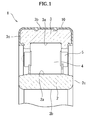
- FIG. 1 is a partial sectional view illustrating a cylindrical roller bearing 1 as a rolling bearing according to the embodiment of the invention.
- FIG. 2 is a partially enlarged explanatory view illustrating the configuration of an electrical insulating film 10 of the cylindrical roller bearing 1 illustrated in FIG. 1 .
- the cylindrical roller bearing 1 illustrated in FIG. 1 includes an inner ring 2, an outer ring 3, a plurality of cylindrical rollers 4 and a cage 5.
- the inner ring 2 has a raceway 2a on its outer peripheral face.
- the outer ring 3 has a raceway 3a on its inner peripheral face.
- the cylindrical rollers 4 are rolling elements disposed between the raceway 2a of the inner ring 2 and the raceway 3a of the outer ring 3.
- the cage 5 holds the cylindrical rollers 4 at prescribed intervals in the circumferential direction of the cylindrical roller bearing 1.
- the electrical insulating film 10 is made of an electrical insulating material that contains heat dissipation additive 11, reinforced fibers 12 and polyphenylene sulfide resin 13 ( FIG. 2 ).
- the heat dissipation additive 11 has high thermal conductivity.
- the reinforced fibers 12 provide high strength to the electrical insulating film 10.
- the polyphenylene sulfide resin 13 has high electrical insulation property.
- masses of the heat dissipation additive 11 are made into contact with each other to form heat transmission paths 15 through which heat is transmitted.
- the electrical insulating film 10 is able to efficiently dissipate the heat generated in the cylindrical roller bearing 1 to the outside of the cylindrical roller bearing 1 through the heat transmission paths 15. Therefore, the cylindrical roller bearing 1 has high electrical insulation property and high strength, and also has a long useful life because a decrease in its useful life due to heat generation is restricted.
- the inner peripheral face 2b and side faces 2c of the inner ring 2 may be coated with the electrical insulating film 10 when the inner ring 2 is made into contact with the housing (not illustrated) or an axle (not illustrated).
- the electrical insulating film 10 preferably has an electrical conductivity of 10 -10 S/m or lower, and more preferably has an electrical conductivity of 10 -12 S/m or lower. From the viewpoint of ensuring sufficient heat dissipation property, the electrical insulating film 10 preferably has a thermal conductivity of 1 W/mK or higher, and more preferably has a thermal conductivity of 2 W/mK or higher.
- the upper limit value of the thermal conductivity of the electrical insulating film 10 is usually 5 W/mK or lower although the upper limit value varies depending on the kind and the amount of the heat dissipation additive 11.
- the electrical insulating film 10 may be formed on the outer peripheral face 3b and the side faces 3c of the outer ring 3 and also on the inner peripheral face 2b and the side faces 2c of the inner ring 2 by, for example, an insert molding process that is performed with the use of the electrical insulating material containing, for example, talc as the heat dissipation additive 11, glass fibers as the reinforced fibers 12 and the polyphenylene sulfide resin 13, a mold, and the bearing rings (inner and outer rings 2, 3) on which the electrical insulating film 10 is formed.
- the electrical insulating material containing, for example, talc as the heat dissipation additive 11, glass fibers as the reinforced fibers 12 and the polyphenylene sulfide resin 13, a mold, and the bearing rings (inner and outer rings 2, 3) on which the electrical insulating film 10 is formed.
- FIG. 3A and FIG. 3B are process charts illustrating an example of the method of manufacturing the electrical insulating resin material according to the embodiment of the invention.
- FIG. 3A is an explanatory view illustrating a step in which a part of the total amount of the heat dissipation additive 11 to be blended, and the total amount of the polyphenylene sulfide resin 13 to be blended are supplied into an kneading extruder body 20a of a twin-screw kneading extruder 20 (hereinafter, referred to as "first material supply step").
- first material supply step hereinafter, referred to as "first material supply step
- 3B is an explanatory view illustrating a step in which the remainder of the total amount of the heat dissipation additive 11 to be blended and the total amount of the reinforced fibers 12 to be blended are supplied into the kneading extruder body 20a of the twin-screw kneading extruder 20 (hereinafter, referred to as "second material supply step).
- the twin-screw kneading extruder 20 may be used as an kneading extruder.
- the twin-screw kneading extruder 20 having a first material supply port 21 and a second material supply port 22 as illustrated in FIG. 4A will be described as an example.
- the second material supply port 22 is located downstream of the first material supply port 21.
- FIG. 4A and FIG. 4B illustrate the configuration of the twin-screw kneading extruder 20 used in the method of manufacturing the electrical insulating resin material according to the embodiment of the invention.
- FIG. 4A and FIG. 4B illustrate the configuration of the twin-screw kneading extruder 20 used in the method of manufacturing the electrical insulating resin material according to the embodiment of the invention.
- FIG. 4A is an explanatory view illustrating tendency of torque distribution in the twin-screw kneading extruder 20 during supply of the materials.
- FIG. 4B is a partially enlarged sectional view illustrating screws of the twin-screw kneading extruder 20.
- a continuous line indicates the torque distribution in the twin-screw kneading extruder 20 when the materials are supplied in parts into the kneading extruder body 20a through the first material supply port 21 and the second material supply port 22.
- the dashed line indicates the torque distribution in the twin-screw kneading extruder 20 when all the materials are supplied into the kneading extruder body 20a through the first material supply port 21.
- the twin-screw kneading extruder 20 illustrated in FIG. 4A includes the kneading extruder body 20a, the first material supply port 21 and the second material supply port 22. In the kneading extruder body 20a, the materials are mixed and kneaded and then the mixture is extruded to the outside through a discharge port 23.
- the first material supply port 21 is formed in an upstream side portion of the kneading extruder body 20a in the extruding direction, and part of the materials is supplied into the kneading extruder body 20a through the first material supply port 21.
- the second material supply port 22 is formed at a position downstream of the first material supply port 21, the remainder of the materials is supplied into the kneading extruder body 20a through the second material supply portion 22.
- Two identical screw bodies 25a, 25b that are rotatably meshed with each other and that are disposed parallel to each other are accommodated in the kneading extruder body 20a.
- the screw bodies 25a, 25b are configured to rotate in the same direction.
- a first heat dissipation additive supply portion 31 and a resin supply portion 32 are disposed above the first material supply port 21.
- the first heat dissipation additive supply portion 31 supplies a part of the total amount of the heat dissipation additive 11 into the first material supply port 21.
- the resin supply portion 32 supplies the polyphenylene sulfide resin 13 into the first material supply port 21.
- a second heat dissipation additive supply portion 33 and a reinforced fiber supply portion 34 are disposed above the second material supply port 22.
- the second heat dissipation additive supply portion 33 supplies the remainder of the heat dissipation additive 11 into the second material supply port 22.
- the reinforced fiber supply portion 34 supplies the reinforced fiber 12 into the second material supply port 22.
- agitation torque detectors such as torque detectors or pressure sensors, which are used to acquire agitation torque, are respectively disposed near the first material supply port 21 and the second material supply port 22 in the kneading extruder body 20a.
- a longitudinal length L (refer to FIG. 4A ) and a maximum diameter D (refer to FIG. 4B ) of each of the screw bodies 25a, 25b is set such that a ratio L/D falls within a range from 50 to 100.
- the value of the ratio L/D should be 50 or higher, and is preferably 70 or higher from the viewpoint of uniformly dispersing the materials and ensuring a sufficient mixing and kneading time, thereby manufacturing a homogeneous electrical insulating material. Further, the value of the ratio L/D should be 100 or lower, and is preferably 80 or lower from the viewpoint of preventing breakage of the reinforced fibers 12 and reducing the time during which the reinforced fibers 12 are exposed to a high temperature due to retention of the materials during the mixing and kneading, thereby suppressing deterioration of the resin.
- the twin-screw kneading extruder 20 having the above-described ratio L/D is used.
- the materials are mixed and kneaded under the condition that the value of the maximum agitation torque when the remainder of the heat dissipation additive 11 and the total amount of the reinforced fibers 12 are both supplied into the kneading extruder body 20a from the second material supply port 22 and then mixed and kneaded, is equal to or lower than the value of the maximum agitation torque when the total amount of the heat dissipation additive 11 and the total amount of the polyphenylene sulfide resin 13 are both supplied into the kneading extruder body 20a from the first material supply port 21 and then mixed and kneaded.
- the values of the maximum agitation torques are the maximum values of torques measured by the agitation torque detectors (not illustrated) that are disposed in the twin-screw kneading extruder 20.
- the above-described configuration is adopted.
- the materials are more efficiently mixed and kneaded, and breakage of the reinforced fibers 12 is during the mixing and kneading of the materials is more reliably suppressed.
- the value of the maximum agitation torque when a part of the total amount of the heat dissipation additive 11 and the total amount of the polyphenylene sulfide resin 13 are both supplied into the kneading extruder body 20a of the twin-screw kneading extruder 20 from the first material supply port 21 and then mixed and kneaded is preferably equal to the value of the maximum agitation torque when the remainder of the heat dissipation additive 11 and the total amount of the reinforced fibers 12 are both supplied into the kneading extruder body 20a of the twin-screw kneading extruder 20 from the second material supply port 22 and then mixed and kneaded.
- the heat dissipation additive 11 for example, talc may be used.
- talc When the talc is used as the heat dissipation additive 11, sufficient heat dissipation property is ensured.
- the shape and size of each mass of the heat dissipation additive 11 are not particularly limited as long as sufficient heat dissipation property is ensured.
- the content rate of the heat dissipation additive 11 in the electrical insulating resin material should be 40 mass% by mass or higher and is preferably 50% by mass or higher from the viewpoint of ensuring sufficient heat dissipation property.
- the upper limit of the content rate of the heat dissipation additive 11 in the electrical insulating resin material is not particularly limited as long as the total mass% of the materials contained in the electrical insulating material is 100%.
- the content rate of the heat dissipation additive 11 should be 80% by mass or lower is preferably 70% by mass or lower and is more preferably 60% by mass or lower from the viewpoint of ensuring the ease in the mixing and kneading of the materials during the manufacturing.
- the reinforced fibers 12 there may be used, for example, glass fibers, whiskers such as zinc oxide whiskers, calcium carbonate whiskers or titanate whiskers.
- the glass fibers are preferable because the glass fibers provide a sufficient strength and are easy to handle.
- the reinforced fibers 12 have a diameter that is preferably 13 ⁇ m or smaller and is more preferably 10 ⁇ m or smaller from the viewpoint of ensuring sufficient moldability and enhancing the strength. Further, the reinforced fibers 12 have a length that is preferably 500 ⁇ m or longer and is more preferably 2,000 ⁇ m or longer from the viewpoint of ensuring sufficient strength.
- the reinforced fibers 12 has a length that is preferably 10,000 ⁇ m or shorter and is more preferably 5,000 ⁇ m or shorter from the viewpoint of ensuring sufficient moldability.
- the diameter and length of the reinforced fibers 12 are the average diameter and average length among 300 reinforced fibers 12.
- the reinforced fibers 12 have an aspect ratio that is preferably 20 or higher and is more preferably 100 or higher from the viewpoint of ensuring sufficient strength.
- the content rate of the reinforced fibers 12 in the electrical insulating resin material should be 15% by mass or higher and is preferably 25% by mass or higher from the viewpoint of ensuring sufficient strength, but should be 40% by mass or lower and is preferably 30% by mass or lower from the viewpoint of ensuring sufficient moldability.
- the polyphenylene sulfide resin 13 is a chemical compound having a molecular weight of 3,000 to 50,000 and containing a structural unit having a molar concentration of 70 to 100 mol% and expressed by the following formula (1).
- the polyphenylene sulfide resin 13 is a chemical compound having a molecular weight within a range from 3,000 to 50,000, and containing the structural unit expressed by the formula (I) having a molar concentration that is 70 mol% or higher but lower than 100 mol%, and at least one kind of structural unit having a molar concentration that is above 0 mol% but 30 mol% or lower and selected from a group consisting of a structural unit expressed by the following formula (II), a structural unit expressed by the following formula (III), a structural unit expressed by the following formula (IV), a structural unit expressed by the following formula (V), a structural unit expressed by the following formula (VI), a structural unit expressed by the following formula (VII), and a structural unit expressed by the following formula (VIII).
- the above-described molecular weight is preferably 3,000 or higher and is more preferably 10,000 or higher from the viewpoint of ensuring sufficient creeping property and sufficient fatigue-resistant property.
- the molecular weight is preferably 50,000 or lower and is more preferably 30,000 or lower from the viewpoint of suppressing an increase in the viscosity of the mixture of the materials, thereby suppressing abrupt increases in the agitation torque and the temperature and from the viewpoint of ensuring the ease in the mixing and kneading of the materials during the manufacturing.
- the polyphenylene sulfide resin 13 is usually in the form of pellets.
- the content rate of the polyphenylene sulfide resin 13 in the electrical insulating resin material is preferably 5% by mass or higher and is more preferably 20% by mass or higher from the viewpoint of ensuring sufficient insulation property and sufficient strength.
- the content rate of the polyphenylene sulfide resin 13 in the electrical insulating resin material is preferably 45% by mass or lower and is more preferably 30% by mass or lower from the viewpoint of suppressing reduction in the heat dissipation property.
- the electrical insulating resin material may further contain, for example, a mold release agent or an oxidation stabilizer (thermal stabilizer).
- a mold release agent for example, stearic acid may be used, but the invention is limited to this example.
- stearic acid allows the molded electrical insulating resin material to be easily removed from, for example, a mold, and suppresses shear resistance.
- the first material supply step a part of the total amount of the heat dissipation additive 11 and the total amount of the polyphenylene sulfide resin 13 are supplied into the kneading extruder body 20a of the twin-screw kneading extruder 20 from the first material supply port 21 (refer to FIG. 3A ).
- the materials (the heat dissipation additive 11 and the polyphenylene sulfide resin 13) supplied into the kneading extruder body 20a from the first material supply portion 21 are moved in the direction from A to B in FIG. 3A while being mixed and kneaded.
- the content of the heat dissipation additive 11 with respect to 100 parts by mass of the polyphenylene sulfide resin 13 is set to a value that is preferably 50 parts by mass or higher and is more preferably 80 parts by mass or higher from the viewpoint of uniformly dispersing the materials.
- the content of the heat dissipation additive 11 is set to a value that is preferably 150 parts by mass or lower and is more preferably 100 parts by mass or lower from the viewpoint of suppressing an increase in the torque during the mixing and kneading and suppressing back-flow and leakage of the materials.
- the screw bodies 25a, 25b are rotated at a rotational speed that is preferably 50 rpm or higher from the viewpoint of uniformly dispersing the materials but preferably 200 rpm or lower from the viewpoint of restraining breakage of the reinforced fibers 12, thereby ensuring sufficient strength.
- the remainder of the heat dissipation additive 11 and the total amount of the reinforced fibers 12 are supplied into the kneading extruder body 20a of the twin-screw kneading extruder 20 from the second material supply port 22, and are then mixed and kneaded at a rotational speed within the range from 50 to 200 rpm.
- the electrical insulating resin material is moved in the direction from A to B in FIG. 3B , and is extruded from the discharge port 23.
- the screw bodies 25a, 25b are rotated at the same rotational speed as that of the screw bodies 25a, 25b in the first material supply step.
- the materials are mixed and kneaded at a rotational speed within the range from 50 to 200 rpm.
- the value of the maximum agitation torque is preferably a value equal to or lower than the value of the maximum agitation torque that is observed when the total amount of the heat dissipation additive 11 and the total amount of the polyphenylene sulfide resin 13 are supplied into the kneading extruder body 20a of the twin-screw kneading extruder 20 from the first material supply port 21 and then the materials are mixed and kneaded at a rotational speed within the range from 50 to 200 rpm. This is because it is possible to sufficiently mix and knead the materials and suppress breakage of the reinforced fibers 12 during the mixing and kneading.
- the mold release or the oxidation stabilizer may be supplied into the kneading extruder body 20a from the second material supply port 22, in the second material supply step, together with the remainder of the heat dissipation additive 11 and the total amount of the reinforced fibers 12.
- the thus obtained electrical insulating resin material contains 15 to 40% of the reinforced fibers 12 by mass, and 5 to 45% of the polyphenylene sulfide resin 13 by mass, and further contains the remaining mass% of the heat dissipation additive 11 so that the total mass% of the materials contained in the electrical insulating resin material is 100%.
- the electrical insulating resin material in the present embodiment contains 40 to 80% of the heat dissipation additive 11 by mass.
- the electrical insulating resin material contains a sufficient amount of the heat dissipation additive 11 with a high density so that desired thermal conductivity is ensured.
- masses of the heat dissipation additive 11 are easily made into contact with each other, so that it is possible to facilitate formation of the heat transmission paths 15.
- the electrical insulating resin material in the present embodiment according to the invention contains 15 to 40% of the reinforced fibers 12 by mass, which are in the condition appropriate for ensuring sufficient strength. Thus, it is possible to ensure sufficient strength and moldability. Further, the electrical insulating resin material contains the polyphenylene sulfide resin 13 having high electrical insulation property. Thus, it is possible to ensure high electrical insulation property.
- a kneading extruder having a plurality of the second material supply ports 22 may be adopted.
- the number of the second material supply ports 22 is denoted by n (n > 3)
- the remainder of the heat dissipation additive 11 remaining after a part the heat dissipation additive 11 is supplied into the kneading extruder body 20a from the first material supply port 21 is supplied in parts into the kneading extruder body 20a by n times.
- talc which may function as the heat dissipation additive 11
- 2,500 grams of the polyphenylene sulfide resin 13 were supplied into the kneading extruder body 20a of the twin-screw kneading extruder 20 (produced by Toshiba Machine Co., Ltd: product name
- Example 2 will be described.
- the same process as that in Example 1 was carried out except that the mixing and kneading performed at a rotational speed of 200 rpm instead of 100 rpm in Example 1, to obtain an electrical insulating resin material containing 50% of the talc by mass, 25% of the glass fibers by mass, and 25% of the polyphenylene sulfide resin 13 by mass.
- the temperature of the mixture of the materials near the second material supply port 22 was confirmed to be 293°C.
- Comparative Example 1 will be described.
- the same process as that in Example 1 was carried out except that the mixing and kneading was performed at a rotational speed of 400 rpm instead of 100 rpm in Example 1, to obtain an electrical insulating resin material containing 50% of the talc by mass, 25% of the glass fibers by mass, and 25% the polyphenylene sulfide resin 13 by mass.
- the temperature of the mixture of the materials near the second material supply port 22 was confirmed to be 323°C.
- Test Example 1 The electrical insulating resin materials obtained in Examples 1, 2 and Comparative Example 1 were molded by extrusion-molding to obtain compacts.
- the bending strength, bending elastic modulus, specific gravity, thermal conductivity, volume resistivity, linear thermal expansion coefficient in a flow direction, linear thermal expansion coefficient in a direction orthogonal to the flow direction (orthogonal direction), mold shrinkage factor in the flow direction and mold shrinkage factor in the orthogonal direction were measured on each of the thus obtained compacts.
- the length of the glass fibers (glass fiber length) contained in each of the electrical insulating resin materials obtained in Examples 1, 2 and Comparative Example 1 were measured. The results of measurements are indicated in Table 1. Note that the above-described measurements are based on the following standards.
- Bending strength JIS K 7171 Bending elastic modulus: JIS K 7171 Specific gravity: JIS Z 8807 Thermal conductivity: JIS R 1611 Volume Resistivity: JIS K 6911 Linear thermal expansion coefficient in flow direction: JIS K 7197 Linear thermal expansion coefficient in orthogonal direction: JIS K 7197 Mold shrinkage factor in flow direction: JIS K 7197 Mold shrinkage factor in orthogonal direction: JIS K 7197 Table 1 Ref. Ex. 1 Ref. Ex.2 Comp. Ex.
- a rolling bearing in which at least one of the inner peripheral face of an inner ring and the outer peripheral face of an outer ring is coated with an electrical insulating film made of the electrical insulating resin material obtained by mixing and kneading the materials at a rotational speed of 200 rpm or lower, preferably at a rotational speed within the range from 50 to 200 rpm, and more preferably at a rotational speed within the range from 100 to 200 rpm, has high electrical insulation property and high heat dissipation property, thereby having a long useful life.
- Test Example 2 will be described.
- the same process as that in Example 1 was carried out except that the amount of the talc that is supplied into the kneading extruder body 20a of the twin-screw kneading extruder 20 from the first material supply port 21 was set to 2,000 grams, 3,000 grams or 4,000 grams, instead of 2,500 grams (50% of the total amount) in Example 1, to obtain electrical insulating resin materials.
- the thus obtained electrical insulating resin materials were then molded by extrusion molding to obtain compacts.
- thermal conductivity of each of the thus obtained compacts was measured on the basis of standards stated in JIS R 1611.
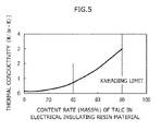
- the relationship between the content rate of the talc in the electrical insulating resin material and the thermal conductivity observed in Test Example 2 is illustrated in FIG. 5 .
- the results illustrated in FIG. 5 suggest that, when the content rate of the talc in the electrical insulating resin material is 40% by mass or higher, in a rolling bearing used in an electric motor for a railway vehicle or the like, a thermal conductivity of equal to or higher than 0.8 W/mK, which is sufficient to efficiently dissipate heat to the outside of the rolling bearing, is ensured. It is deemed that the content rate of the talc in the electrical insulating resin material is preferably 70% by mass or lower, because the mixing and kneading tends to be insufficient if the content rate of the talc in the electrical insulating resin material exceeds 80% by mass.
- the heat dissipation additive in an amount sufficient to ensure desired thermal conductivity and the reinforced fibers in a condition appropriate for ensuring sufficient strength are uniformly dispersed in the polyphenylene sulfide resin that has high electrical insulation property.
- the rolling bearing according to the invention has advantages that the rolling bearing has high electrical insulation property and high heat dissipation property and thus has a long useful life.
Landscapes
- Engineering & Computer Science (AREA)
- Mechanical Engineering (AREA)
- Processing And Handling Of Plastics And Other Materials For Molding In General (AREA)
- Processes Of Treating Macromolecular Substances (AREA)
- Compositions Of Macromolecular Compounds (AREA)
- Extrusion Moulding Of Plastics Or The Like (AREA)
Applications Claiming Priority (1)
| Application Number | Priority Date | Filing Date | Title |
|---|---|---|---|
| JP2013146861A JP2015016667A (ja) | 2013-07-12 | 2013-07-12 | 電気絶縁樹脂材料の製造方法ならびに転がり軸受 |
Publications (1)
| Publication Number | Publication Date |
|---|---|
| EP2823947A1 true EP2823947A1 (fr) | 2015-01-14 |
Family
ID=51022779
Family Applications (1)
| Application Number | Title | Priority Date | Filing Date |
|---|---|---|---|
| EP14175392.1A Withdrawn EP2823947A1 (fr) | 2013-07-12 | 2014-07-02 | Procédé de fabrication d'un matériau de résine d'isolation électrique et palier à roulement |
Country Status (3)
| Country | Link |
|---|---|
| EP (1) | EP2823947A1 (fr) |
| JP (1) | JP2015016667A (fr) |
| CN (1) | CN104275751A (fr) |
Families Citing this family (1)
| Publication number | Priority date | Publication date | Assignee | Title |
|---|---|---|---|---|
| JP7139571B2 (ja) * | 2015-11-04 | 2022-09-21 | Dic株式会社 | ポリアリーレンスルフィド樹脂組成物および成形品 |
Citations (11)
| Publication number | Priority date | Publication date | Assignee | Title |
|---|---|---|---|---|
| US4482668A (en) * | 1982-10-15 | 1984-11-13 | Phillips Petroleum Company | Poly(arylene sulfide) containing talc |
| EP0327884A1 (fr) * | 1988-02-05 | 1989-08-16 | Bayer Ag | Polyarylènesulfides chargés à retrait anisotrope réduit |
| DE3917516A1 (de) * | 1989-05-30 | 1990-12-06 | Bayer Ag | Graphitierte polyarylensulfid-formmassen |
| JPH03277818A (ja) | 1990-03-26 | 1991-12-09 | Ntn Corp | 電食防止転がり軸受 |
| US6191675B1 (en) * | 1998-04-22 | 2001-02-20 | Hitachi, Ltd. | High voltage transformer and ignition transformer using the same |
| US20080268322A1 (en) * | 2005-12-30 | 2008-10-30 | Cheil Industries Inc. | Composition for Fuel Cell Bipolar Plate |
| JP2008260830A (ja) * | 2007-04-11 | 2008-10-30 | Idemitsu Kosan Co Ltd | 伝熱性樹脂組成物 |
| JP2010285581A (ja) * | 2009-06-15 | 2010-12-24 | Toyota Motor Corp | 絶縁樹脂組成物 |
| JP5041209B2 (ja) | 2005-12-28 | 2012-10-03 | Dic株式会社 | 耐熱性樹脂組成物、その製造方法、耐熱性樹脂成形物、及び表面実装用電子部品 |
| JP2012236298A (ja) * | 2010-06-10 | 2012-12-06 | Shin Kobe Electric Mach Co Ltd | 樹脂成形品 |
| WO2012173223A1 (fr) * | 2011-06-15 | 2012-12-20 | Ntn株式会社 | Procédé de fabrication de palier multicouche et palier multicouche |
Family Cites Families (1)
| Publication number | Priority date | Publication date | Assignee | Title |
|---|---|---|---|---|
| JP5771860B2 (ja) * | 2011-09-27 | 2015-09-02 | 住友化学株式会社 | 樹脂組成物の製造方法 |
-
2013
- 2013-07-12 JP JP2013146861A patent/JP2015016667A/ja not_active Withdrawn
-
2014
- 2014-07-02 EP EP14175392.1A patent/EP2823947A1/fr not_active Withdrawn
- 2014-07-10 CN CN201410327713.9A patent/CN104275751A/zh active Pending
Patent Citations (12)
| Publication number | Priority date | Publication date | Assignee | Title |
|---|---|---|---|---|
| US4482668A (en) * | 1982-10-15 | 1984-11-13 | Phillips Petroleum Company | Poly(arylene sulfide) containing talc |
| EP0327884A1 (fr) * | 1988-02-05 | 1989-08-16 | Bayer Ag | Polyarylènesulfides chargés à retrait anisotrope réduit |
| DE3917516A1 (de) * | 1989-05-30 | 1990-12-06 | Bayer Ag | Graphitierte polyarylensulfid-formmassen |
| JPH03277818A (ja) | 1990-03-26 | 1991-12-09 | Ntn Corp | 電食防止転がり軸受 |
| US5375933A (en) * | 1990-03-26 | 1994-12-27 | Ntn Corporation | Rolling contact bearing protected against electrolytic corrosion |
| US6191675B1 (en) * | 1998-04-22 | 2001-02-20 | Hitachi, Ltd. | High voltage transformer and ignition transformer using the same |
| JP5041209B2 (ja) | 2005-12-28 | 2012-10-03 | Dic株式会社 | 耐熱性樹脂組成物、その製造方法、耐熱性樹脂成形物、及び表面実装用電子部品 |
| US20080268322A1 (en) * | 2005-12-30 | 2008-10-30 | Cheil Industries Inc. | Composition for Fuel Cell Bipolar Plate |
| JP2008260830A (ja) * | 2007-04-11 | 2008-10-30 | Idemitsu Kosan Co Ltd | 伝熱性樹脂組成物 |
| JP2010285581A (ja) * | 2009-06-15 | 2010-12-24 | Toyota Motor Corp | 絶縁樹脂組成物 |
| JP2012236298A (ja) * | 2010-06-10 | 2012-12-06 | Shin Kobe Electric Mach Co Ltd | 樹脂成形品 |
| WO2012173223A1 (fr) * | 2011-06-15 | 2012-12-20 | Ntn株式会社 | Procédé de fabrication de palier multicouche et palier multicouche |
Also Published As
| Publication number | Publication date |
|---|---|
| JP2015016667A (ja) | 2015-01-29 |
| CN104275751A (zh) | 2015-01-14 |
Similar Documents
| Publication | Publication Date | Title |
|---|---|---|
| JP5582877B2 (ja) | フィルムキャパシタ用フィルムの製造方法及びフィルムキャパシタ用フィルム | |
| US9115254B2 (en) | Resin composition, foamed resin using same, and electric wire insulated with foamed resin | |
| US8623801B2 (en) | Electrically conductive polyethylene resin composition, electrically conductive polyethylene resin molding sliding bearing, and sliding sheet | |
| JP5328626B2 (ja) | フィルムキャパシタ用フィルムの製造方法及びフィルムキャパシタ用フィルム | |
| EP3915758A1 (fr) | Vis et extrudeuse | |
| US8790558B2 (en) | Method for manufacturing film for film capacitor | |
| CN115926413B (zh) | 高分子聚合物制品及其制备方法和应用 | |
| JP2006104395A (ja) | 樹脂組成物、並びにそれを用いる絶縁電線、電線ケーブル、チューブ及び熱収縮チューブ | |
| US8524133B2 (en) | Method for manufacturing resin film for thin film-capacitor and the film therefor | |
| EP2823947A1 (fr) | Procédé de fabrication d'un matériau de résine d'isolation électrique et palier à roulement | |
| EP3075718A1 (fr) | Procédé de fabrication de corps formés de céramique et appareil de fabrication de corps formés de céramique | |
| JP2018008405A (ja) | 非晶性熱可塑性樹脂フィルムの製造方法 | |
| US20190152104A1 (en) | Production method for resin molding | |
| JP2016141128A (ja) | ゴムロールの製造方法、及びゴムロールの製造装置 | |
| CN111057334B (zh) | 热塑性氟树脂组合物的制造方法、电线的制造方法以及电缆的制造方法 | |
| US12337505B2 (en) | Method for producing fiber-reinforced composite material | |
| CN118786185A (zh) | 滑动用树脂组合物及滑动部件 | |
| JP2017109859A (ja) | 紙送りローラおよびその製造方法 | |
| JP2010215796A (ja) | 発泡樹脂組成物及びその製造方法、並びにこれを用いた発泡絶縁電線 | |
| WO2023167118A1 (fr) | Composition de résine destinée à coulisser, et élément coulissant | |
| JP5870738B2 (ja) | 絶縁電線 | |
| JP2017110179A (ja) | 帯電防止剤およびその製造方法 | |
| JPH08100818A (ja) | 電食防止転がり軸受 | |
| JP6414973B2 (ja) | 紙送りローラの製造方法 | |
| CN109070426B (zh) | 螺杆式挤出机 |
Legal Events
| Date | Code | Title | Description |
|---|---|---|---|
| 17P | Request for examination filed |
Effective date: 20140702 |
|
| AK | Designated contracting states |
Kind code of ref document: A1 Designated state(s): AL AT BE BG CH CY CZ DE DK EE ES FI FR GB GR HR HU IE IS IT LI LT LU LV MC MK MT NL NO PL PT RO RS SE SI SK SM TR |
|
| AX | Request for extension of the european patent |
Extension state: BA ME |
|
| PUAI | Public reference made under article 153(3) epc to a published international application that has entered the european phase |
Free format text: ORIGINAL CODE: 0009012 |
|
| R17P | Request for examination filed (corrected) |
Effective date: 20150709 |
|
| RBV | Designated contracting states (corrected) |
Designated state(s): AL AT BE BG CH CY CZ DE DK EE ES FI FR GB GR HR HU IE IS IT LI LT LU LV MC MK MT NL NO PL PT RO RS SE SI SK SM TR |
|
| 17Q | First examination report despatched |
Effective date: 20150806 |
|
| STAA | Information on the status of an ep patent application or granted ep patent |
Free format text: STATUS: EXAMINATION IS IN PROGRESS |
|
| STAA | Information on the status of an ep patent application or granted ep patent |
Free format text: STATUS: THE APPLICATION IS DEEMED TO BE WITHDRAWN |
|
| 18D | Application deemed to be withdrawn |
Effective date: 20161213 |