EP2824002B2 - Procédé destiné à ouvrir ou fermer un véhicule automobile - Google Patents
Procédé destiné à ouvrir ou fermer un véhicule automobile Download PDFInfo
- Publication number
- EP2824002B2 EP2824002B2 EP14176077.7A EP14176077A EP2824002B2 EP 2824002 B2 EP2824002 B2 EP 2824002B2 EP 14176077 A EP14176077 A EP 14176077A EP 2824002 B2 EP2824002 B2 EP 2824002B2
- Authority
- EP
- European Patent Office
- Prior art keywords
- sensor
- motor vehicle
- user
- detection
- sensors
- Prior art date
- Legal status (The legal status is an assumption and is not a legal conclusion. Google has not performed a legal analysis and makes no representation as to the accuracy of the status listed.)
- Active
Links
Images


Classifications
-
- B—PERFORMING OPERATIONS; TRANSPORTING
- B60—VEHICLES IN GENERAL
- B60R—VEHICLES, VEHICLE FITTINGS, OR VEHICLE PARTS, NOT OTHERWISE PROVIDED FOR
- B60R25/00—Fittings or systems for preventing or indicating unauthorised use or theft of vehicles
- B60R25/20—Means to switch the anti-theft system on or off
- B60R25/24—Means to switch the anti-theft system on or off using electronic identifiers containing a code not memorised by the user
- B60R25/246—Means to switch the anti-theft system on or off using electronic identifiers containing a code not memorised by the user characterised by the challenge triggering
-
- B—PERFORMING OPERATIONS; TRANSPORTING
- B60—VEHICLES IN GENERAL
- B60R—VEHICLES, VEHICLE FITTINGS, OR VEHICLE PARTS, NOT OTHERWISE PROVIDED FOR
- B60R25/00—Fittings or systems for preventing or indicating unauthorised use or theft of vehicles
- B60R25/20—Means to switch the anti-theft system on or off
- B60R25/2045—Means to switch the anti-theft system on or off by hand gestures
-
- E—FIXED CONSTRUCTIONS
- E05—LOCKS; KEYS; WINDOW OR DOOR FITTINGS; SAFES
- E05F—DEVICES FOR MOVING WINGS INTO OPEN OR CLOSED POSITION; CHECKS FOR WINGS; WING FITTINGS NOT OTHERWISE PROVIDED FOR, CONCERNED WITH THE FUNCTIONING OF THE WING
- E05F15/00—Power-operated mechanisms for wings
- E05F15/70—Power-operated mechanisms for wings with automatic actuation
- E05F15/73—Power-operated mechanisms for wings with automatic actuation responsive to movement or presence of persons or objects
-
- E—FIXED CONSTRUCTIONS
- E05—LOCKS; KEYS; WINDOW OR DOOR FITTINGS; SAFES
- E05Y—INDEXING SCHEME ASSOCIATED WITH SUBCLASSES E05D AND E05F, RELATING TO CONSTRUCTION ELEMENTS, ELECTRIC CONTROL, POWER SUPPLY, POWER SIGNAL OR TRANSMISSION, USER INTERFACES, MOUNTING OR COUPLING, DETAILS, ACCESSORIES, AUXILIARY OPERATIONS NOT OTHERWISE PROVIDED FOR, APPLICATION THEREOF
- E05Y2400/00—Electronic control; Electrical power; Power supply; Power or signal transmission; User interfaces
- E05Y2400/80—User interfaces
- E05Y2400/85—User input means
- E05Y2400/852—Sensors
-
- E—FIXED CONSTRUCTIONS
- E05—LOCKS; KEYS; WINDOW OR DOOR FITTINGS; SAFES
- E05Y—INDEXING SCHEME ASSOCIATED WITH SUBCLASSES E05D AND E05F, RELATING TO CONSTRUCTION ELEMENTS, ELECTRIC CONTROL, POWER SUPPLY, POWER SIGNAL OR TRANSMISSION, USER INTERFACES, MOUNTING OR COUPLING, DETAILS, ACCESSORIES, AUXILIARY OPERATIONS NOT OTHERWISE PROVIDED FOR, APPLICATION THEREOF
- E05Y2400/00—Electronic control; Electrical power; Power supply; Power or signal transmission; User interfaces
- E05Y2400/80—User interfaces
- E05Y2400/85—User input means
- E05Y2400/856—Actuation thereof
- E05Y2400/858—Actuation thereof by body parts, e.g. by feet
-
- E—FIXED CONSTRUCTIONS
- E05—LOCKS; KEYS; WINDOW OR DOOR FITTINGS; SAFES
- E05Y—INDEXING SCHEME ASSOCIATED WITH SUBCLASSES E05D AND E05F, RELATING TO CONSTRUCTION ELEMENTS, ELECTRIC CONTROL, POWER SUPPLY, POWER SIGNAL OR TRANSMISSION, USER INTERFACES, MOUNTING OR COUPLING, DETAILS, ACCESSORIES, AUXILIARY OPERATIONS NOT OTHERWISE PROVIDED FOR, APPLICATION THEREOF
- E05Y2900/00—Application of doors, windows, wings or fittings thereof
- E05Y2900/50—Application of doors, windows, wings or fittings thereof for vehicles
- E05Y2900/53—Type of wing
- E05Y2900/546—Tailboards, tailgates or sideboards opening upwards
Definitions
- the invention relates, inter alia, to a method for actuating a virtual switch according to claim 1.
- Such virtual switches serve to actuate a movable part, such as a tailgate, a door or the like in a vehicle, in particular a motor vehicle. This is intended to increase the comfort of the vehicle, since it is possible to open the movable part without needing to use your hands.
- the method according to the invention is carried out with the aid of a module unit with a sensor device for actuating a movable part, in particular a flap of a motor vehicle, with a carrier body on which the sensor device with at least one sensor is arranged in order to enable detection of an object in at least one detection area adjacent to the motor vehicle, so that the actuation of the movable part can be activated via the detection.
- the actuation preferably takes place without contact.
- the invention is directed only to one actuation method.
- Sensor devices are known for the contactless actuation of moving parts of a motor vehicle, which sense the presence and in particular the movement of a person in order to detect the desire to open the moving part of the motor vehicle.
- the moving part of the motor vehicle can relate to a flap and in particular a tailgate or a side door or bonnet of the motor vehicle, whereby movable window elements are also known, such as a rear window that can be moved in a tailgate, which can then be advantageously opened or closed by a generic sensor device if manual actuation of the tailgate is not possible or only possible with difficulty.
- the movable part is referred to simply as a flap.
- An exemplary sensor device is shown in the DE 10 2005 032 402 B3 described.
- the object detected by the sensor device can be a person who approaches the motor vehicle with the intention of opening the tailgate.
- the actuation of the tailgate describes both an opening process, for example if the person wants to put an object into the trunk with both hands, or the actuation of the tailgate refers to a closing process of the tailgate if the person has taken an object out of the trunk with both hands in order to then close the tailgate.
- the known sensor device comprises at least one sensor which is arranged on the motor vehicle via a carrier body.
- the sensors for operating the tailgate are usually attached to the inside of the bumper, so that the carrier body is formed by the bumper itself. It is known to glue or laminate the sensors to the inside of the surface of the bumper, with the sensors being designed as capacitive electrodes in the form of wires or foils.
- the wires or foils of the sensors formed by electrodes are attached at least over part or preferably over the entire width of the bumper of the motor vehicle.
- the tailgate of the motor vehicle can be operated from various areas in the immediate vicinity of the rear of the motor vehicle.
- the sensors are therefore part of the rear bumper and are glued to the inside of the bumper or attached to the bumper with fastening means.
- the disadvantage is that the installation effort for such sensor devices is high.
- the object of the present invention is therefore to provide a method that enables increased operational reliability of the virtual switch. In particular, false signals from the virtual switch are to be avoided.
- the present invention is achieved by the features of claim 1, in particular from the characterizing part. Advantageous embodiments of the invention are listed in the dependent subclaims.
- the term "movable part” is understood to mean any door, side or sliding door, flap or the like of a vehicle that has at least one closed state and one open state, the closed state being achieved by an electrical and/or mechanical lock in order to prevent unwanted or unauthorized opening.
- the lock of this movable part can interact with a central locking system, preferably as an "active” or "passive keyless-go system", of the vehicle.
- the vehicle itself can be a motor vehicle.
- the present invention provides a method for actuating a virtual switch with a sensor system that detects an actuation of the switch, the sensor system having at least two contactless sensors. These contactless sensors can expediently be designed as proximity sensors, namely capacitance sensors.
- the invention provides a method for opening or closing a motor vehicle with at least one movable part, in the form of a flap or a tailgate, which is automatically opened or closed after detection of a contactless, conscious actuation, comprising a leg or foot movement, by a user, wherein a sensor device is provided for actuation of a movable part, which has at least one sensor, by means of which at least two detection areas are formed, within which a respective detection of the actuation is made possible, wherein both detection areas each have a horizontal area extending from the motor vehicle for detecting the actuation, wherein an actuation of the movable part is triggered when at least one body part of the user is detected in both detection areas.
- the invention provides that the method is carried out with the aid of a modular unit which is designed with the sensor device and with a carrier body on which the sensor device with the at least one sensor is arranged, wherein the modular unit is designed as an individually handleable module such that the modular unit can be fastened to the motor vehicle, and wherein a checking module is arranged on the modular unit which checks the functioning of the sensor device, in particular of the individual sensors.
- An essential core of the present invention is that the method is carried out using an individually handled module that can be easily attached to the motor vehicle, in particular to the rear area.
- appropriate fastening elements are preferably provided on the module unit, with which the module unit can be reliably arranged on the motor vehicle.
- the module unit can be attached to a part on the motor vehicle in a form-fitting, force-fitting and/or material-fitting manner. For example, it is conceivable that the module unit is latched, clipped or pushed into a motor vehicle part. An adhesive connection is also conceivable.
- the module unit, in particular the carrier body consists at least partially of plastic.
- the sensors are capacitive sensors.
- an electrical unit in particular a control unit, connected to the sensor device is arranged on the carrier body.
- This electrical unit forwards the signals transmitted by the sensors to a main electrical unit that is arranged on the motor vehicle side.
- the electrical unit can wirelessly transmit signals from the main electrical unit on the motor vehicle side.
- the sensor device can be integrated into the electrical unit.
- the sensor device advantageously has at least a first and a second sensor, wherein the sensors have different detection areas, wherein in particular the different detection areas are of different sizes.
- the module unit can be designed such that at least one sensor has a lateral arrangement on the motor vehicle, i.e. is not arranged on the rear of the motor vehicle, but on a side area of the motor vehicle.
- the carrier body can be fastened to the motor vehicle in a form-fitting, force-fitting and/or material-fitting manner, wherein in particular the carrier body can be fastened to the motor vehicle via a snap-in connection or can be inserted into the motor vehicle.
- the corresponding motor vehicle-side part on which the carrier body is arranged can be designed with corresponding fastening elements that interact with the fastening elements of the carrier body for reliable fixation.
- the module unit is arranged on the emblem of the motor vehicle or has an emblem of the motor vehicle, wherein the emblem is visibly arranged on the motor vehicle.
- the motor vehicle has a pivoting tailgate.
- a rear camera device is provided as a parking aid on the motor vehicle, in particular on the tailgate.
- the module unit is integrated on the tailgate and/or at least partially on the rear camera device.
- the module unit can comprise a first and a second sensor, which are arranged within the rear camera device.
- the sensor preferably has an elongated extension, with the sensor in particular being designed to be flexible.
- One of the advantages of a flexible sensor device is that it offers advantages during assembly.
- the sensor device and/or the electrical unit can be attached to the carrier body in a form-fitting, force-fitting and/or material-fitting manner.
- the sensor device and/or the electrical unit can be integrated in the carrier body, in particular the sensor device and/or the electrical unit can form a monolithic component with the carrier body.
- the sensor device has an extension which is of the motor vehicle, whereby in particular the sensors run essentially parallel to one another.
- a measure extending the invention can provide that the electrical unit is in data communication with, in particular connected to, at least one further third sensor that is arranged on the motor vehicle side.
- the third sensor can be arranged in the tire, on the rear camera device, on a license plate lighting unit, on a trim strip, on a bumper, on a lock cylinder of a locking unit, in a locking unit for locking the steering, in a windshield wiper arrangement, in a rear light, in a handle of the motor vehicle.
- the third sensor can be, for example, a heat sensor, a distance sensor, a voice sensor, an image sensor, in particular for field of view recognition.
- positioning means can be provided to ensure that the carrier body is clearly attached to the motor vehicle.
- the positioning means can, for example, be recesses or cutouts formed on the carrier body that can only be arranged in one position on the component of the motor vehicle to be attached. This ensures that the sensors arranged on the carrier body also have the desired position for reliable detection of an object in the area of the motor vehicle.
- the electrical unit preferably has a circuit board on which the sensors are arranged, with the circuit board and the sensors being integrated in particular within a casting compound.
- the module unit can also have a plastic housing within which the sensor device including the electrical unit is located. The housing can be fixed to the motor vehicle using appropriate fastening means.
- At least one sensor can be integrated as a partial sensor within the carrier body, with at least one contact point of the partial sensor protruding from the carrier body. This means that a first partial sensor is located within the carrier body, with a second partial sensor being attached to the carrier body and both partial sensors being connected via contact points, so that both partial sensors form an overall sensor.
- the carrier body preferably has a receptacle in which the electrical unit is located, in particular a cover element seals the receptacle.
- the cover element can, for example, be designed with a corresponding seal so that no dirt, moisture, etc. gets into the receptacle and thus disrupts the functionality of the electrical unit.
- the carrier body expediently has at least one stiffening element, which in particular is also the sensor.
- the stiffening element can be, for example, a metal strip or metal plate, which reinforces the carrier body in its construction. In the special embodiment of the invention, this stiffening element can serve as an electrode, which thus takes over the function of the sensor in order to be part of the sensor device.
- a checking module which checks the functioning of the sensor device.
- the checking module can, for example, be located near the respective sensor, wherein the checking module is preferably attached to the carrier body.
- an emergency switch accessible from the outside can be provided, which can be activated via a tactile action of the user.
- touching the emergency switch can also trigger a signal that can activate the moving part.
- the activation of the movable part after a positive detection by the sensor device means that the movable part can be moved from its closed position to its open position and vice versa.
- an actuation of the movable part i.e. a movement of the movable part, into its open position and/or closed position only occurs when a positive authentication has also taken place with the object.
- This authentication is usually carried out using an ID transmitter that the authorized person carries with them.
- the ID transmitter has a corresponding identification code that is checked on the vehicle side for authentication.
- the movable part is only actuated accordingly if authentication is positive.
- the power supply to the electrical unit can be inductive.
- the electrical unit has a coil element which interacts with a counter-coil element and a corresponding power supply to the electrical unit can be provided inductively.
- a lighting unit can be provided which is activated in particular during detection. It is conceivable that the lighting unit gives the user feedback via a defined lighting mode. For example, indicators or tail lights can be used as Light units can be used to light up or flash during or after successful detection and/or authentication. Additionally or alternatively, an acoustic signal can also provide the user with appropriate feedback during or after successful detection and/or authentication.
- a measure improving the invention can provide for a threshold value control that detects when the user actually touches the movable part. If the user leans directly on the movable part or touches this part without wanting to activate an actual operation of the movable part, this detects the threshold value control, so that an opening process of the movable part is not activated.
- At least one sensor is arranged between the carrier body and the motor vehicle-side component, wherein in particular the carrier body is designed with a profile that is directed towards the motor vehicle-side component and offers the sensor a specific installation position that is sealed in particular to the outside.
- the electrical unit can be attached to the vehicle or to the carrier body of the module unit in a form-fitting and/or force-fitting manner using counter-holding elements via holding elements.
- These holding elements can be designed as latching elements or clip elements or the like in order to securely attach the electrical unit, in particular the control unit, to the vehicle or the carrier body of the module unit.
- the holding elements are integrated into the housing of the electrical unit in order to be able to interact mechanically with the vehicle, for example.
- the holding elements are integrated into the vehicle, in particular the bumper, the door sill or the like, or the carrier body of the module unit. These holding elements work together with counter-holding elements on the other element.
- the electrical unit can be attached to the vehicle directly or indirectly via the holding elements, for example in a hanging or standing position.
- buffer elements are provided with which the electrical unit is supported on the vehicle-side element or the carrier body of the module unit and which absorb a significant part of the weight of the electrical unit. These buffer elements can be used to cushion and/or dampen tolerances and vibrations that inevitably arise in a vehicle in order to protect the electrical unit as far as possible from mechanical influences.
- the holding elements are integrated with the buffer elements in order to attach the electrical unit to the vehicle or to the carrier body of the module unit.
- both the holding elements and the buffer elements can be molded, welded, glued, screwed or otherwise attached directly to the housing in order to accommodate the electrical unit securely on the vehicle.
- Corresponding counter elements which can consist of a hole, for example, or also of locking elements, can be attached in the same way as the holding elements, for example to the bumper, door sill or support body of the module unit or the like.
- the holding elements can have additional metal clips, or screw elements or the like, which are used to attach the electrical unit.
- At least one sensor can be designed as a wire or a conductor foil, which in particular has an elongated extension. It is also conceivable that at least one sensor is designed as a foil or flat, with the elongated extension in particular being significantly larger than the width of the corresponding sensor.
- the sensor can be arranged on the motor vehicle in the bumper area or in the door sill area or lower door area of the side doors. The carrier body from the module unit can be used for this purpose. It is also conceivable that this sensor extends over the entire width or only a partial area of the width of the bumper or door sill. It is also conceivable that several sensor devices or several module units are used in a motor vehicle, for example to operate the side doors, the trunk lid and/or the engine compartment lid as a movable part.
- At least one sensor can also be arranged directly on the moving part. This arrangement is particularly interesting on the side doors, as there is little space to arrange the sensor device on the fixed body of the vehicle.
- the installation of a sensor in or on the moving part also offers the possibility of the moving part following the object in the detection area by controlling a drive for the moving part through the sensor device. This makes it possible, for example, for the side door to be opened independently by the operator's hand or foot (the object) by simply attempting to remove the hand from the sensor's detection area, with the sensor detecting this movement and instructing the drive to have the moving part follow the object so that it remains in the sensor's detection area.
- the detection area of the sensors should not extend into the swivel area of the movable flap, as this could lead to collisions with the object to be detected. Unless the corresponding sensor is used to make the moving part follow the object, as previously described.
- the sensor device first carries out a reference measurement with at least one sensor in order to initially detect interference such as weather, obstacles or the like.
- This reference measurement value can be stored in the electrical unit, in particular in the control unit, as a reference value.
- the sensor can then measure the detection of an object in the detection area. In this way, malfunctions when the movable part is actuated can be reliably avoided.
- the sensor device carries out the reference measurement mentioned during or shortly after the parking process in order to detect objects in the detection area, for example, which could later lead to measurement errors when the movable flap is actuated.
- This reference measurement can also be used to set threshold values for the subsequent measurement. It should be mentioned at this point that it is optionally possible to switch the sensor device on or off using an additional switch in the vehicle.
- the activation of the sensor device can also be controlled by the vehicle's electronics, e.g. via the steering wheel lock or the starter switch or a switch on the gear lever or the like.
- a sensor can be equipped with a terminal resistor located at the end of the sensor electrode. A comparative measurement can thus be used to determine whether the resistance can still be measured or not. If the terminal resistor is no longer detected, it can be assumed that there is a defect or break in the sensor somewhere, which can be recorded as an error by the control unit and reported to the vehicle electronics.
- the sensor element can be designed in a loop or U-shape so that the input connection and the output connection of the sensor element can be arranged next to each other.
- At least one sensor is equipped with a shielding element.
- This shielding element can be partially wrapped around the sensor as a shielding film in order to define the detection area of the sensor more precisely.
- the detection area of the sensor is then geometrically defined at the exposed areas of the sensor that are not covered or concealed by the shielding film.
- a sensor designed across the entire width of a motor vehicle can only be directed at the corner areas of the motor vehicle (transition from the rear area to the side area) by the shielding element.
- a so-called active shield is used for one or each sensor in order to direct the detection area forwards away from the active shield.
- the respective sensor is thus arranged between its detection area and its active shield.
- the respective sensor can be partially or completely covered in plastic or rubber with the shielding element and/or the active shield.
- the sensor can be covered, for example, using an injection molding or extrusion process.
- the corresponding sensor thus forms an inseparable component with its shielding element and/or its active shield.
- the sensor can also be arranged separately from its shielding element and/or its active shield.
- the sensor can also be attached directly or indirectly to the vehicle or the support part of the module unit using a mat or net, with the sensor being fully or partially embedded in the mat or net.
- the mat or net can then be attached indirectly using additional holding elements, in particular locking elements or clips - as described.
- An additional connection can be made in the area of the clips to improve sensing.
- the sensor device has a first sensor with a first horizontal detection area and at least one second sensor with a second horizontal detection area on the motor vehicle, in order to not only detect the entry of the object into the detection area of a sensor, but also the corresponding movement of the object.
- two consecutive different directions e.g. raising, lowering, pivoting, rotating
- two consecutive different directions e.g. raising, lowering, pivoting, rotating
- At least one capacitive coupling of a sensor is changeable. It is also conceivable that the capacitive coupling of the other sensors is also designed to be changeable or that this only takes place after a change to a first sensor.
- the capacitive change can also be controlled via a threshold value, so that, for example, the first sensor is triggered but the second sensor detects that the object has already entered its detection area but is not yet fully present. This means that the actuation of the moving part can also be controlled specifically by the object only partially entering the detection area of a sensor.
- an access authorization system and/or a security system is only activated when at least one sensor in the sensor device detects an object in its detection range.
- the access authorization system or the security system can only be activated when it is ensured that this object actually wants access to the vehicle. This can take place, for example, by successfully detecting a movement sequence of the object or by two or more sensors detecting the object in the detection range. It is therefore also conceivable that the access authorization system and/or the security system is only activated when the measured value of a sensor falls or will fall below a predetermined threshold.
- access to the vehicle is only granted once the access authorization system and/or the security system with a mobile ID transmitter has successfully carried out a security query for the access code.
- this query can be made dependent on the measurement result of the sensor device, as described above.
- At least one sensor of the sensor device serves as an antenna or as an additional antenna for the access authorization system and/or the security system.
- the query of the access authorization system for example via the mobile ID transmitter or a keyless go card, can but does not have to serve to activate the sensor device. Rather, the sensor device can also serve to wake up the access authorization system and/or the security system.
- the additional query of the ID transmitter simply represents a further improvement in security in order to prevent unauthorized opening of the movable part of the motor vehicle.
- the detection of an object can occur both when the vehicle is locked and when it is open.
- the sensor device can also be used to control or activate the camera device, in particular the rear camera device, in order to avoid, for example, mechanical collisions between the vehicle or just the moving part and the environment during the opening process. It is also conceivable that other technical means are provided for the aforementioned camera in order to prevent the moving part from colliding with an obstacle or object during opening or closing.
- This can also be, for example, another proximity sensor, a radar system or an ultrasonic sensor or the like. This ensures that the opening or closing process of the moving part takes place - for example only after possible authentication - when it is ensured that there is no object or obstacle in the movement range of the moving part. This can be particularly important in low garages.
- At least one sensor of the sensor device is used to determine whether an object, in particular a person, is in the movement area of the moving part. Only when the sensor ensures that no object is detected can the control of the moving part by the electronic unit, in particular the control unit, be released in order to operate the moving part. This can effectively reduce the risk of entrapment.
- the other sensor systems in the vehicle such as the parking system, the distance warning system or the like, can also be used to determine that a person at risk is outside the danger area of the moving part.
- a sensor of the sensor device can be arranged on the vehicle by means of holding elements, in particular on the inside of the bumper or the movable part or on the door sill area.
- the holding elements themselves can be designed as clips or locking elements.
- the clips themselves can also be designed to be adhesive-bonded, for example to hold the sensor in a materially bonded manner.
- Form-fitting loops or holding means can also be provided on the clips for fastening the sensor.
- At least one sensor can be connected to the module unit via the carrier body. It is also conceivable that a separate carrier body is provided for each sensor in order to form the module unit. Of course, several sensors can also be arranged next to one another, in parallel or one behind the other on one carrier body. It is also conceivable that at least one sensor element is arranged outside the module unit, with another sensor being provided on the carrier element of the module unit.
- At least one sensor can be arranged in a meandering or loop-shaped manner to form its detection area.
- This design of the sensor is particularly important when the sensor is not only supposed to detect whether an object is completely in the detection area or not, but also when the sensor is supposed to detect whether the object has completely or partially penetrated its detection area.
- This design of the sensor is therefore particularly suitable when working with threshold values during the measurement.
- several sensors of the sensor device can also be designed in this way.
- the sensor device additionally supports a parking system or a driving guidance system or even completely replaces it for short distances, i.e. less than 2 m.
- the measurement signals recorded by the sensor device can therefore also be used to support the driving safety of the motor vehicle, especially when parking or at low speeds.
- a sensor is additionally equipped with a heating element or that a corresponding heating element is arranged near a sensor in order to allow water in the area of the sensor to evaporate as quickly as possible through additional heat.
- This heating element can also be used to thaw frozen water that has frozen onto the sensor or in the immediate vicinity. This can significantly increase the measurement accuracy, since water in particular causes major measurement interference with a capacitive sensor.
- the heating element is temporarily switched on and off by the electrical unit depending on the weather, in order to regularly ensure that the immediate vicinity of the respective sensor is free of water. It should also be mentioned that it is conceivable to use the sensor itself or, for example, a shielding element for the sensor as a heating element. The control unit can ensure this by, for example, switching the sensor or the shielding element on once as a heating element and using it again as a sensor or shielding element. Of course, an additional heating element can also be present to generate the required heat.
- the heating element can be combined with the sensor and, if applicable, the shielding element to form one component, for example by means of a casing or insulation.
- water-guiding elements either directly on the sensor, the carrier body for the module unit or the bumper, the door sill or the like, with the help of which an attempt is made to divert existing water as far as possible from the detection area of the corresponding sensor.
- the water-guiding elements themselves can be designed as projections or tear-off edges or as drainage channels or holes. This is intended to prevent a water film from forming, particularly in the direct detection area of the sensor.
- the water-guiding elements can, for example, be designed in a wedge shape, which forms a tear-off edge for a watercourse, at which the water drops then separate from the water-guiding element.
- the water-guiding element can also consist of just a tear-off edge that is incorporated into the carrier body or the bumper or the like.
- Water channels or openings for draining or guiding the water away from the sensor are also conceivable, which are arranged on the carrier body or the vehicle, in particular the bumper, the door sill or the like.
- the first and then the second sensor are activated for detection or that both sensors are activated simultaneously for detection.
- a first and a second sensor are provided, wherein the object, in particular the authorized user, performs a conscious action that is detected by the first or second sensor.
- first the first and then the second sensor are activated for detection or that both sensors are activated simultaneously for detection.
- a leg or foot movement of the user is detected by the first sensor and a further body movement of the user is detected by the second sensor.
- At least one lighting unit of the motor vehicle has a defined lighting mode.
- the module unit is arranged at the rear and/or at the side door area of the motor vehicle, in particular underneath a side sliding door.
- the sliding door can be opened by detecting a person who is near the side sliding door of the motor vehicle. This embodiment is particularly useful for vehicles that are designed as commercial vehicles, in particular as vans or small vans.
- the electrical unit is connected to at least one third sensor and/or switch which is arranged inside the motor vehicle, in particular that the third sensor and/or switch is arranged in the motor vehicle in such a way that it can be connected via the foot, and/or knee and/or and/or elbow and/or shoulder and/or head of the user.
- an opening and/or closing movement of the side sliding door can be triggered by activating the third sensor and/or switch. If the user is inside the motor vehicle, the sliding door of the motor vehicle can be closed by activating the third sensor and/or switch. The side sliding door can also be opened again by activating the third sensor and/or switch.
- the third sensor and/or switch can be designed as a proximity sensor, a contactless sensor or a tactile pressure switch.
- the third sensor and/or switch for triggering an opening movement and/or closing movement of the side sliding door of the motor vehicle is arranged in or on the side sliding door.
- An arrangement in or on the door panel, on the vehicle seat or in the floor area or on various decorative elements within the motor vehicle is also conceivable.
- a closing movement of the side sliding door can be triggered by the user activating the internal third sensor and/or switch, for example. It is also conceivable that when leaving the vehicle, the user must first activate the internal third sensor and/or switch. Then, further detection of the sensor of the module unit is necessary in order to trigger an actual closing process of the side sliding door. Furthermore, it is also conceivable that the internal third sensor can be triggered via a defined movement pattern.
- the third sensor can be deactivated depending on the operating state of the motor vehicle. This means that when the engine is "running” or activated, the third sensor and/or switch for opening the side sliding door is deactivated. However, it can be provided that such deactivation can be deactivated again by the user, so that the user can trigger a closing movement and/or opening movement of the side sliding door via the third sensor and/or switch even when the engine is "running".
- an actuation of the third sensor can trigger the unlocking and/or locking of another motor vehicle door and/or tailgate and/or fuel tank flap.
- the speed of the opening movement and/or closing movement of the sliding door is variable, in particular the electrical unit controls and/or regulates the speed of the opening movement and/or closing movement of the sliding door.
- the method according to the invention can be designed in such a way that the actual activation of the movable part takes place after a defined time and/or depending on a defined distance that the user must have from the module unit.
- a defined time is specified which triggers the opening of the movable part with a time delay after a positive detection and/or after a positive authentication process.
- Due to the design of the motor vehicle, in particular of the movable part it can also be advantageous that the movable part only opens when the user is at a defined distance from the movable part. This means that the necessary distance from the user is determined via the sensor device located in the module unit. In one possible embodiment, it may be necessary for the user to first move away from the movable part so that an actuation of the movable part is triggered.
- the module unit is designed with its own lighting unit, which communicates the necessary distance to the user according to its lighting mode. If the user is still too close to the vehicle, the lighting unit can, for example, signal the user with a first color. If the user is at a sufficient distance from the module unit, the lighting unit changes its color and the opening movement of the movable part can take place.
- the authentication process is started and the sensor device is activated via an ID transmitter that the user carries with him, even though the user in particular is outside the detection range.
- the method according to the invention offers the possibility of the user being able to operate the ID transmitter at a greater distance from the motor vehicle, so that the authentication process is initially triggered. Only when the user is near the motor vehicle, in particular the module unit, does the sensor device detect this in order to activate the actuation of the movable part. This means that the authentication process takes place before the detection process for actuating the movable part.
- the sensor device can already be activated after positive authentication.
- the movable part is actuated depending on a speed signal. This means that the movable part can only be actuated when the motor vehicle is stationary and not moving.
- a third sensor is provided, whereby the flap opens upon positive detection via the first and second sensors, and the flap closes upon positive detection via the first and second sensors.
- third sensor opens a disc arranged on the flap and upon positive detection via the second and third sensors the flap closes.
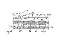
- Fig. 1 shows, purely schematically, a possible embodiment variant of the module unit 10, which is designed with a sensor device 11 for actuating a movable part, in particular a flap of a motor vehicle.
- the module unit 10 has a carrier body 12, on which the sensor device 11 with at least one sensor 21 is arranged.
- the sensor 21 is attached to the carrier body 12 via fastening means 35.
- the sensor 21 has an elongated design that extends transversely to the direction of the vehicle. Parallel to the schematically shown sensor 21, a further sensor 22 can be attached to the carrier body 12 at a distance, which is not explicitly shown.
- a third sensor 23 can also be attached above the sensor 11 in the area of the fastening means 35, which are located on the upper edge area of the module unit 10.
- the module unit 10 further comprises an electrical unit 13 which is connected both to the sensor device 11 and to a motor vehicle-side main electrical unit 27, which is shown by way of example in Fig. 11 shown.
- a check module 26 is arranged on the module unit 10, which checks the functionality of the sensor device 11, in particular of the individual sensors 11.
- the carrier body 12 is made of a plastic.
- the carrier body 12 and the module unit 10 are designed as individually handled modules in such a way that the module unit 10 can be attached to the motor vehicle in a simple manner. This means that the module unit 10 can be connected to all the Fig. 1 shown components can be attached to a motor vehicle part by the worker during assembly.
- fastening elements 14 are shown purely schematically in the present embodiment, with which a fixation to the motor vehicle can be achieved. Furthermore, an emergency switch 28 is provided, which can be activated tactilely by the user. If the sensor device 11 is malfunctioning, the user can actuate this emergency switch 28 in order to trigger a corresponding activation of the movable part 1.
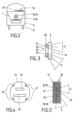
- a motor vehicle 2 which has an emblem 15 on which, for example, the vehicle brand can be shown.
- the emblem 15 is in the module unit 10 integrated.
- the sensor device 11 has at least two sensors 21, 22.
- Fig. 3 is a possible sectional view in the area of the emblem 15 according to Fig. 2
- the motor vehicle 2 has two fixing elements 36 on the inside, within which the module unit 10 is fastened.
- a first sensor 21 and a second sensor 22 are fastened in the carrier body 12.
- the emblem 15 is visibly attached to the outside.
- the carrier body 12 is designed as an independent component visible from the outside for the user, with the carrier body 12 only carrying the emblem 15 on its outer surface, which is shown schematically in Fig. 2
- the first sensor 21 has a first detection area 5 and the second sensor 22 has a second detection area 6.
- the detection areas 5, 6 can be of different sizes.
- the module unit 10 can be designed as a license plate lighting unit 9, which in Fig. 2 as well as in Fig. 7 is shown.
- the module unit 10 has two light units 29, 32, which serve to illuminate the license plate of the motor vehicle.
- the module unit 10 is also designed with the electrical unit 13.
- the sensor device 11 is designed with a third sensor 23 in the middle.
- the sensor 23 can work as a parking aid.
- the first sensor 21 and the second sensor 22 are also arranged on the module unit 10, with the third sensor 23 being arranged centrally between the first sensor 21 and the second sensor 22.
- other positionings of the first sensor 21 and the second sensor 22 are conceivable.
- Fig. 2 A further embodiment is indicated in which the module unit 10 can communicate with a third sensor 23, which is integrated on the motor vehicle side, in particular on a windshield wiper arrangement 16.
- Fig. 4 the carrier body 12 is shown, on which the first sensor 21 and the second sensor 22 are arranged.
- the carrier body 12 also has four positioning means 17 so that the fitter can achieve a clear fixation of the carrier body 12 to the motor vehicle component when fastening the module unit 10.
- These positioning means are designed as recesses. Alternative geometric embodiments and alternative positioning means are also conceivable.
- the module unit 10 is shown with the sensor device 11, wherein the electrical unit 13 has a circuit board 18 on which the first sensor 21 and the second sensor 22 are arranged.
- a shielding element 37 is provided between the two sensors 21, 22. In the case of the sensors 21, 22 as capacitive sensors, the shielding element 37 helps to ensure a satisfactory functioning of the overall arrangement.
- the first detection area 5 is assigned to the first sensor 21 and the second detection area 6 to the second sensor 22.
- the electrical unit 13 is enclosed in a casting compound 19, which acts as a carrier body 12.
- the module unit 10 can, as in Fig. 1 already discussed, can be fixed to the vehicle using various fastening options.
- the module unit 10 has a first sensor 21 and a second sensor 22.
- a third sensor 23 can be integrated into the module unit 10.
- the third sensor 23 has a third detection area 40.
- the tailgate 1 can be opened via a positive detection via the first sensor 21 and the second sensor 22.
- a window 33 movably arranged on the flap 1 can be opened via a positive detection via the first sensor 21 and the third sensor 23.
- the object only has to approach the first sensor 21.
- the movement of the window 33 is then activated via a foot movement in the detection area 40.
- the flap 1 and/or the window 33 can be closed again via a positive detection via the second sensor 22 and the third sensor 23.
- a motor vehicle 2 is schematically indicated, which is designed with a module unit 10 at its rear, which has a first sensor 21 and a second sensor 22, each of which is equipped with different detection areas 5, 6.
- the detection area 5 is directed horizontally, whereas the detection area 6 has a slight incline, but still has a significant horizontal detection area, without creating a detection area at the ground level of the roadway.
- the detection process can be carried out in such a way that both the first sensor 21 and the second sensor 22 detect an object at the same time.
- the detection ranges of the detection areas are of different sizes.
- the detection area 5 has a small effective range, which means that the object must come very close to the module unit 10 in order to be detected by the sensor 5.
- the detection area 6 is effective at a greater distance than the first detection area 5.
- Detection can be carried out in such a way that an object 4 is first detected by the second sensor 22. The object must then come very close to the first sensor 21 for a positive detection to occur in order to activate a corresponding actuation of the movable part 1. It is also conceivable that the object 4 is first detected by the first sensor 21 and then the second sensor 22 is activated in order to detect the object 4 within its second detection range.
- the method according to the invention shown relates to a motor vehicle (2) with at least one movable part, in particular a flap (1) or tailgate (1), which can be opened or closed automatically by a user or object (4) after a contactless, conscious action (for example leg or foot movement), at least one sensor (21, 22) being provided, by means of which at least two detection areas (5, 6) are formed, within which a respective detection of the desire to open is made possible, both detection areas (5, 6) each having a horizontal area extending from the motor vehicle (2) for detecting the desire to open, an actuation of the flap being able to be triggered if at least one body part of the user (4) is detected in both detection areas (5, 6).
- the flap (1) is formed by the tailgate of the motor vehicle (2), the detection areas (5, 6) each having a horizontally aligned rear and/or partially lateral area of the motor vehicle (2) extending from the motor vehicle (2) for detecting the desire to open.
- the detection areas (5, 6) are aligned at least in such a way horizontally that a demarcation of the detection areas (5, 6) is created downwards in the direction of the roadway.
- Two sensors (21, 22) are provided, each having one or more sensor electrodes for creating the detection areas (5, 6), wherein an effective area is preferably formed by two or more sensor electrodes.
- a single sensor (21, 22) which has two sensor electrodes for creating the detection areas (5, 6), wherein an effective area is preferably formed by two or more sensor electrodes.
- a control device is provided which is connected to the sensor (21, 22) for detecting at least one sensor signal, wherein the sensor signal can then be output from the sensor(s) (21, 22) to the control device when the user's (4) desire to open the door is detected by the sensor(s) (21, 22). It is advantageous if the user's (4) desire to open the door can be detected by the at least one sensor (21, 22) when the user (4) performs a movement with a body part according to a predeterminable movement pattern within the at least one detection area (5, 6).
- the body part of the user (4) can be a leg and/or a foot of the user (4) which penetrates into the detection areas (5, 6) and/or is moved within them, and wherein the movement of the leg is preferably a lifting of the leg and the movement of the foot is preferably a pivoting foot.
- the user's (4) desire to open the door can be detected by the at least one sensor (21, 22) when the movement of a body part of the user (4) in a first effective area has a predeterminable time offset relative to a movement of a body part of the user (4) in a second effective area.
- the method according to the invention is very cost-effective when one or each sensor electrode is designed as a flat element or as a wire or as a cable, with a bumper on the motor vehicle (2) in or on which the or each flat element can be arranged.
- the structural design is very simple when the sensor electrodes are designed as capacitive sensor electrodes and the installation situation or environment of the sensor electrodes has a capacitance whose change can be detected by the sensors (21, 22).
- an access authorization means is provided which can be connected to the control unit by means of a wireless connection and can be interrogated by the control unit, so that the flap can only be activated or released if the mobile ID transmitter or a Keyless Go card is present.
- the invention relates to a method for actuating a movable part (1, 33), in particular a flap (1) of a motor vehicle, with a module unit (10) which has a carrier body (12) on which a sensor device (11) with at least one sensor (21, 22, 23) is arranged in order to enable detection (3) of an object (4) in at least one detection area (5, 6, 40) adjacent to the motor vehicle (2), so that the actuation of the movable part (1, 33) can be activated via the detection (3), wherein at least one sensor (21, 22, 23) is provided, by means of which at least two detection areas (5, 6, 40) are formed, and at least two detection areas each have a horizontal area for detection extending from the motor vehicle, and a flap (1) can be triggered when at least one object is detected in both detection areas, wherein an authentication process (31) is provided which checks the extent to which the object (4) is authorized to operate the movable part (1,33), the authentication process (31) taking place before the detection (3).
- the essential advantage of the method according to the invention is that accidental opening or closing of the hatch of the motor vehicle is avoided even when a user is standing next to the motor vehicle and an object, for example a ball or a cat, is moving underneath the motor vehicle.
- a first (21) and a second sensor (22) are provided here, the object (4), in particular the authorized user (4), performing a conscious action which is detected by the second sensor (22).
- the object (4) in particular the authorized user (4)
- performing a conscious action which is detected by the second sensor (22).
- first the first (21) and then the second sensor (22) are activated.
- both sensors (21,22) can be activated simultaneously for detection (3).
- a leg or foot movement of the user (4) can be detected by the first sensor (21) and a further body movement of the user (4) can be detected by the second sensor (22).
- the actual activation of the movable part (1, 33) takes place after a defined time and/or depending on a defined distance that the user (4) has from the module unit (10). It is advantageous if the authentication process (31) is started and the sensor device (11) is activated via an ID transmitter that the user (4) wears, even though the user is outside the detection area (5, 6, 40). In addition, the activation of the actuation of the movable part (1, 33) can take place depending on a speed signal.
- the capacitive sensors comprise a metallic, conductive material, silver.
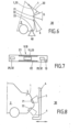
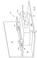
- Fig. 9 A further embodiment is shown purely schematically, in which the module unit 10 is arranged within a rear camera device 7 of a tailgate 1.
- a third sensor 23 is located on the vehicle side on a bumper and has its detection area 40.
- the third sensor 23 can be addressed via a leg or foot movement of the user.
- the third sensor 23 is arranged within the tire 8.
- the third sensor 23 within the tire 8 can be addressed by a targeted kick against the tire 8.
- the sensor 23 within the tire 8 can be a pressure sensor, for example, which detects such a tire impact.
- Fig. 10 shows purely schematically a possible embodiment of the carrier body 12, on which a first sensor 21 and a second sensor 22 are arranged, which have their corresponding detection areas 5 and 6.
- the carrier body 12 has a corresponding profile 38, with a receptacle 24 in which the electrical unit 13 is arranged.
- a cover element 25 is placed on the profile 38, which is additionally designed with a seal 34.
- the electrical unit 13 can be completely cast within the module carrier 10.
- the module carrier 10 is attached to the motor vehicle 2 or to the movable part 1.
- the first sensor 21 is designed as a stiffening element.
- the first sensor 21 is located inside the carrier body 12, with a contact point 20 of the first sensor 21 protruding from the carrier body 12.
- the electrical unit 13 is placed on the contact point 20.
- the second sensor 22 is attached to the carrier body 12 at a distance from the first sensor 21.
- the second sensor 22 is connected to the electrical unit 13 via a cable element.
- the module unit 10 is attached to a motor vehicle part 1, 2.
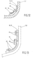
- Fig..13 shows a further embodiment of a module unit 10, wherein a sensor 21 is integrated as a partial sensor within the carrier body 12.
- the second partial sensor 21 is located on the inside of the carrier body 12. Both partial sensors are electrically connected to one another, wherein both partial sensors form the first sensor 21, which as in Fig. 12 has an external contact point 20 to which the electrical unit 13 is connected.
- the electrical unit 13 is connected to the carrier body 12 via a screw connection.
- the second sensor 22 is also formed by two partial sensors, the first partial sensor being placed on the inside of the carrier body 12 and the second partial sensor running inside the carrier body 12.
- the second sensor 22 also has a corresponding external contact point 20 which is connected to the electrical unit 13.
- the module unit 10 can be attached to a motor vehicle part 1, 2.
- the external profile 38 is designed with web-like extensions that lie directly on the motor vehicle part 2 and ensure reliable sealing and insulation of the first sensor 21.
- the first sensor 21 is connected to the electrical unit 13. Furthermore, a second sensor 22 is integrated within the carrier body 12.
- the sensor 21 is also formed by the partial sensor 21 located within the carrier body 12 and the partial sensor 21 located within the outer profile 38. It is of course conceivable that only one sensor element 21 is arranged in the respective receptacle 24 of the external profile 38. In the present exemplary embodiment, the first sensor 21 is located at least partially between the carrier body 12 and the motor vehicle part 2.
- the sensor device 11 is located between the carrier body 12 and the motor vehicle part 1,2 and that the carrier body 12 is positioned between the sensor device 11 and the motor vehicle part 1,2.
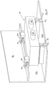
- Fig. 16 shows another alternative of a possible positioning of the module unit 10.
- the module unit is located 10 on the door sill of the side sliding door 42 of the motor vehicle 2.
- the side sliding door 42 can be moved according to the double arrow illustration.
- the side sliding door 42 is in an open state.
- the module unit 10 can have a design which, for example, is shown in the Figures 1 to 15 has been described. If the sliding door 42 is in the closed state, the sensor device of the module unit 10 can detect an authorized user in the vicinity of the sliding door 42, whereby a corresponding actuation or opening movement of the side sliding door 42 can be triggered.
- a third sensor 23 or at least one of the following third sensors can be arranged within the motor vehicle 2, which are provided with the reference numerals 23.1, 23.2, 23.3, 23.4 and 23.5.
- the sensor 23.1 can be actuated via the user's foot.
- the sensor 23.2 can be actuated via the user's knee.
- the sensor 23.3 can be actuated via the user's elbow and/or shoulder.
- the sensor 23.4 can be actuated via the user's head.
- the sensor 23.5 can be activated via the user's foot, knee or elbow. If the user is inside the motor vehicle 2, a closing movement of the side sliding door 42 can be triggered by activating one of the third sensors 23 mentioned.
- the third sensors 23 are connected to the electrical unit 13, in particular the control unit, so that both the sensors inside the module unit 10 and the internal sensors 23 communicate with the same electrical unit.
- the user can trigger the opening movement of the side sliding door 42 by activating a third sensor 23 located inside.
- a third sensor 23 located inside.
- an authentication can take place in parallel, during which it is checked to what extent the user is actually the authorized user in order to realize such an opening movement. Authentication is usually carried out using an ID transmitter, which will be discussed below.
- the speed of the opening movement and/or the closing movement of the sliding door 42 can be changed.
- a speed setting is controlled or regulated via the electrical unit within the module unit 10.
- the electrical unit can be connected to a rain sensor.
- the control unit can, for example, provide a high speed for the opening movement and/or closing movement.
- Fig. 15 It is shown purely schematically that the detection process 3, in which the sensor device 11 is active, can be accompanied by an authentication process 31, in which it is checked to what extent the authorized person is allowed to trigger an actuation of the movable part. If the person carries a corresponding "correct" ID transmitter, a positive authentication takes place. This authentication 31 takes place before the detection 3.
- the detection here only includes the checking of a possible person or a possible object in the vicinity of the module unit 10, whereupon in the Figures 1 to 16 has been discussed in detail.
- step 39 the subsequent activation of the actuation of the movable part, i.e. the opening process or the closing process of the movable part, takes place, but only if both a positive authentication 31 and a positive detection 3 are present.
- the electrical unit 13 has a housing with two beam-shaped feet 51. With these two feet 51, the housing of the electrical unit 13 is supported on the carrier body 12, in particular a lower cross member 12.2, of the module unit 10.
- the feet 51 are in the present Fig. 17 However, it is not attached to the carrier body 12, so that additional holding elements 50 are used, which are also attached to the carrier body 12, in particular an upper cross member 12.1.
- the two holding elements 50 are arranged in the upper rear area on the left and right sides of the housing of the electric unit 13. These holding elements 50 are, for example, firmly connected to the housing in order to enable a mechanically secure hold.
- the holding elements 50 themselves interact with counter-holding elements 50' on the carrier 12, in particular a first cross member 12.1.
- conical or ramp-shaped projections can be provided on the U-shaped holding elements 50, which interact in a form-fitting manner with the counter-holding elements 50' designed as bores on the first cross member 12.1.
- the electric unit 13 is thus securely attached to the carrier body 12 or the bumper or the door sill or the like directly or indirectly to the vehicle 2, even in the event of strong mechanical influences.
- the upper cross member 12.1 and the lower cross member 12.2 are provided on the carrier body 12, which more or less form a U-shaped receptacle 24 for the electrical unit 13.
- the electrical unit 13 stands with its feet 51 on the lower cross member 12.2, although a hanging attachment to the first cross member 12.1 would also be conceivable.
- the feet 51 in the Figure 17 can themselves be made of an elastic material in order to absorb mechanical shocks. It is also conceivable that the electrical unit 13 is only connected to the Support feet 51 are connected to the support body 12 or the vehicle 2 in a form-fitting and/or force-fitting and/or material-fitting manner.
- the feet 51 are arranged in U-shaped buffers 52 in order to enable a positive fastening on the one hand and a shock-absorbing mounting of the electronic unit 13 on the vehicle 2 or carrier body 12 on the other hand.
- the U-shaped receptacle in the buffer elements 52 is designed to be open towards the front, although it can also be closed so that the electrical unit 13 is also attached to the carrier element 12 at the front by the buffer elements 52.
- cylindrical feet 51 or the like can be used, which interact with corresponding complementary buffer elements 52 on the vehicle 2 or carrier body 12.
- the U-shaped holding elements 50 have basic metal clips 53 which engage in the upper cross member 12.1 of the carrier body 12 in order to hold the electrical unit 13 in a form-fitting and/or force-fitting manner on the carrier body 12.
- two sensor connections 21', 22' are shown for the first sensor 21 and the second sensor 22.
- a third or further sensor can also be provided.
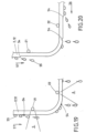
- a first water guide element 54 in the form of a wedge-shaped element is provided above the first sensor 21 on the outside of the carrier body 12 or on the bumper of the motor vehicle 2. If the water 55 (see arrow 57) now runs along the outside, that is the side facing away from the sensors 21 and 22, it reaches the first water element 54 under the influence of gravity. Due to the existing adhesion forces, the water 55 flows along the ramp-shaped water guide element 54 and separates from the carrier body 12 or the bumper, door sill or the like at the lower tear-off edge of the water guide element 54.
- the water 55 then drips from this tear-off edge onto the floor, so that it is reliably prevented from flowing further along the outside and reaching the detection area 5 of the first sensor 21. This ensures that the water does briefly pass through the detection area 5, but is not constantly there, as in an exemplary flow movement.
- another water guide element 54 which is approximately triangular in shape and also forms a tear-off edge for the water 55 flowing along. This also reliably prevents the water 55 from moving further along the outside of the carrier body 12 into the detection area 6 of the second sensor 22.
- the detection areas 5 and 6 are shown purely schematically in the Figure 19 for the two sensors 21 and 22.
- another water guide element 54 is arranged, which is designed in a similar way to the previously described triangular water guide element. This right water guide element 54 ensures that water 55 is also guided past the detection area 6 from the right side.
- the water guide elements 54 consist of a tear-off edge for the water 55.
- This water guide element 54 is also intended to ensure that the water 55 does not simply flow along the outer surface or possibly the inner surface of the carrier 12 or bumper, door sill or the like and enter the detection area 5, 6 of the sensors 21, 22.
- the middle water guide element 54 which is arranged on the left on the outer side of the second sensor 22, has a triangular or wedge-shaped incision in order to form a tear-off edge for the water 55.
- the arrow 57 shown represents the normal flow direction for the water 55.
- the additional arrow 56 indicates the wind direction when the vehicle 2 is moving, which also influences the flow direction of the water 55.
- the right water guide element 54 is also shown only as a tear-off edge for the sensor 22.
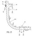
- inner water-guiding elements 54 are also provided for the sensors 21, 22.
- a projection is provided above the first sensor 21, which serves as a water-guiding element 54.
- the lower edge of the projection-like water guide element 54 serves as a tear-off edge for the water drops 55 flowing along it.
- a triangular water guide element 54 is provided on the outer side of the carrier body 12.
- the two inner and outer water guide elements 54 for the first sensor 21 are arranged at approximately the same height on the carrier body 12. Important for this geometric However, the arrangement is such that the flowing water is separated from the surface of the carrier body 12 before the detection area 5.
- a bore, opening or slot or the like is provided in the carrier body 12 so that the water 55 collected within the carrier body 12 can escape.
- This water guide element 54 can also be arranged to the left and right of the second sensor 22 in order to prevent the water drops 54 present in the detection area 6 of the second sensor 22 from flowing away.
- At least one sensor can be designed as an optical sensor.
- the Figure 22 a three-dimensional view of two water guide elements 54 designed as elongated holes under the sensor 22 is shown. As already mentioned, it is also expedient to arrange these water guide elements 54 designed as elongated holes on the left and right side next to the corresponding sensor 21, 22, which also makes it easier to attach the corresponding sensor 21, 22.
- a bumper, a door sill, a side sill, a stone chip protection or the like can also be used as a carrier for the sensors on the vehicle 2 - as already mentioned several times.
Landscapes
- Engineering & Computer Science (AREA)
- Mechanical Engineering (AREA)
- Human Computer Interaction (AREA)
- Lock And Its Accessories (AREA)
- Power-Operated Mechanisms For Wings (AREA)
- Control Of Position, Course, Altitude, Or Attitude Of Moving Bodies (AREA)
- Vehicle Step Arrangements And Article Storage (AREA)
Claims (14)
- Procédé d'ouverture ou de fermeture d'un véhicule automobile (2) avec au moins une partie mobile, sous forme d'un volet (1) ou d'un hayon (1), qui est ouverte ou fermée automatiquement après captage d'une action d'actionnement consciente sans contact comprenant un mouvement de jambe ou de pied par un utilisateur (4), dans lequel un dispositif de capteur (11) pour un actionnement d'une partie mobile est prévu, qui présente au moins un capteur (21, 22), au moyen duquel sont formées au moins deux zones de détection (5, 6) à l'intérieur desquelles un captage respective de l'action d'actionnement est possible, les deux zones de détection (5, 6) présentant chacune une zone horizontale partant du véhicule automobile (2) pour le captage de l'action d'actionnement, un actionnement de la partie mobile étant déclenché lorsqu'au moins une partie du corps de l'utilisateur (4) est détectée dans les deux zones de détection (5, 6), dans lequel un processus d'authentification (31) est prévu pour vérifier dans quelle mesure l'utilisateur (4) est autorisé à actionner la partie mobile (1, 33), le processus d'authentification (31) ayant lieu avant la détection (3),
dans lequel le procédé est mis en oeuvre à l'aide d'une unité modulaire (10) qui est conçue avec le dispositif de capteur (11) et avec un corps de support (12) sur lequel est disposé le dispositif de capteur (11) avec l'au moins un capteur (21, 22), l'unité modulaire (10) étant conçue comme un module (10) pouvant être géré individuellement de telle sorte que l'unité modulaire (10) peut être fixée sur le véhicule automobile (2), une unité électrique (13) reliée au dispositif de capteur (11) étant disposée sur le corps de support (12), et l'unité électrique (13) transmettant les signaux transmis par l'au moins un capteur (21, 22) à une unité électrique principale qui est disposée côté véhicule à moteur, et un module de contrôle (26) qui contrôle le fonctionnement du dispositif de capteur (11), en particulier des différents capteurs (21, 22), étant disposé sur l'unité modulaire (10), dans lequel les capteurs capacitifs (21, 22) comprennent un matériau conducteur métallique de l'argent. - Procédé selon la revendication 1, caractérisé en ce que le volet (1) est formé par le hayon du véhicule automobile (2), les zones de détection (5, 6) présentant chacune une zone arrière et/ou partiellement latérale du véhicule automobile (2) orientée horizontalement et émanant du véhicule automobile (2) pour le captage de la volonté d'ouverture.
- Procédé selon la revendication 1 ou 2, caractérisé en ce que les zones de détection (5, 6) sont alignées horizontalement au moins de manière à créer une délimitation des zones de détection (5, 6) vers le bas en direction de la chaussée.
- Procédé selon l'une des revendications précédentes, caractérisé en ce que deux capteurs (21, 22) sont prévus, chacun ayant une ou plusieurs électrodes de capteur pour fournir les zones de détection (5, 6), de préférence une zone effective étant formée par deux ou plusieurs électrodes de capteur.
- Procédé selon l'une des revendications précédentes, caractérisé en ce qu'il est prévu un seul capteur (21, 22) comprenant deux électrodes de capteur pour fournir les zones de détection (5, 6), de préférence une zone effective étant formée par deux ou plusieurs électrodes de capteur.
- Procédé selon l'une des revendications précédentes, caractérisé en ce qu'il est prévu un dispositif de commande qui est relié au capteur (21, 22) pour le captage d'au moins un signal de capteur, le signal de capteur pouvant être délivré par le ou les capteurs (21, 22) au dispositif de commande lorsque la volonté d'ouverture par l'utilisateur (4) est détecté par le ou les capteurs (21, 22).
- Procédé selon l'une des revendications précédentes, caractérisé en ce que si la volonté d'ouverture par l'utilisateur (4) est détectable par l'au moins un capteur (21, 22) lorsque l'utilisateur (4) effectue un mouvement avec une partie du corps selon un modèle de mouvement prédéterminable à l'intérieur de l'au moins une zone de détection (5, 6).
- Procédé selon l'une des revendications précédentes, caractérisé en ce que la partie du corps de l'utilisateur (4) est une jambe et/ou un pied de l'utilisateur (4) qui entre et/ou est déplacé dans les zones de détection (5, 6), et dans lequel le mouvement de la jambe est de préférence un soulèvement de la jambe et le mouvement du pied est de préférence un pivotement du pied.
- Procédé selon l'une des revendications précédentes, caractérisé en ce que la volonté d'ouverture par l'utilisateur (4) peut être détecté par l'au moins un capteur (21, 22) lorsque le mouvement d'une partie du corps de l'utilisateur (4) dans une première zone effective présente un décalage temporel prédéterminable par rapport à un mouvement d'une partie du corps de l'utilisateur (4) dans une deuxième zone effective.
- Procédé selon l'une des revendications précédentes, caractérisé en ce qu'une ou chaque électrode de capteur est formée comme un élément en forme de feuille ou comme un fil ou comme un câble, où un pare-chocs est présent sur le véhicule automobile (2), dans ou sur lequel le ou chaque élément en forme de feuille peut être disposé.
- Procédé selon l'une des revendications précédentes, caractérisé en ce que la structure constructive, si les électrodes de capteur sont conçues comme des électrodes de capteur à action capacitive et la situation d'installation ou l'environnement des électrodes de capteur présente une capacité dont la variation peut être détectée par les capteurs (21, 22).
- Procédé selon l'une des revendications précédentes, caractérisé en ce qu'il est prévu un moyen d'autorisation d'accès qui peut être connecté au dispositif de commande au moyen d'une connexion sans fil et qui peut être interrogé par le dispositif de commande, de sorte que le volet ne peut être libéré que si l'émetteur d'identification mobile ou une carte de passage sans clé est présent.
- Procédé selon l'une des revendications précédentes, caractérisé en ce qu'au moins un capteur est configuré comme un capteur optique.
- Procédé selon l'une des revendications précédentes, caractérisé en ce qu'il est prévu une unité d'éclairage qui est activée, en particulier lors de la détection, l'unité d'éclairage fournissant un retour à l'utilisateur via un mode d'éclairage défini.
Applications Claiming Priority (3)
| Application Number | Priority Date | Filing Date | Title |
|---|---|---|---|
| DE102010060364A DE102010060364A1 (de) | 2010-11-04 | 2010-11-04 | Verfahren für ein Kraftfahrzeug |
| PCT/DE2011/075261 WO2012059100A2 (fr) | 2010-11-04 | 2011-11-04 | Procédé relatif à un véhicule à moteur |
| EP11837297.8A EP2635464B1 (fr) | 2010-11-04 | 2011-11-04 | Procédé d'ouverture ou cloture d'un véhicule automobile |
Related Parent Applications (2)
| Application Number | Title | Priority Date | Filing Date |
|---|---|---|---|
| EP11837297.8A Division-Into EP2635464B1 (fr) | 2010-11-04 | 2011-11-04 | Procédé d'ouverture ou cloture d'un véhicule automobile |
| EP11837297.8A Division EP2635464B1 (fr) | 2010-11-04 | 2011-11-04 | Procédé d'ouverture ou cloture d'un véhicule automobile |
Publications (4)
| Publication Number | Publication Date |
|---|---|
| EP2824002A2 EP2824002A2 (fr) | 2015-01-14 |
| EP2824002A3 EP2824002A3 (fr) | 2015-04-01 |
| EP2824002B1 EP2824002B1 (fr) | 2021-05-12 |
| EP2824002B2 true EP2824002B2 (fr) | 2025-02-19 |
Family
ID=45971193
Family Applications (2)
| Application Number | Title | Priority Date | Filing Date |
|---|---|---|---|
| EP14176077.7A Active EP2824002B2 (fr) | 2010-11-04 | 2011-11-04 | Procédé destiné à ouvrir ou fermer un véhicule automobile |
| EP11837297.8A Active EP2635464B1 (fr) | 2010-11-04 | 2011-11-04 | Procédé d'ouverture ou cloture d'un véhicule automobile |
Family Applications After (1)
| Application Number | Title | Priority Date | Filing Date |
|---|---|---|---|
| EP11837297.8A Active EP2635464B1 (fr) | 2010-11-04 | 2011-11-04 | Procédé d'ouverture ou cloture d'un véhicule automobile |
Country Status (4)
| Country | Link |
|---|---|
| EP (2) | EP2824002B2 (fr) |
| CN (1) | CN103189245B (fr) |
| DE (2) | DE102010060364A1 (fr) |
| WO (1) | WO2012059100A2 (fr) |
Families Citing this family (41)
| Publication number | Priority date | Publication date | Assignee | Title |
|---|---|---|---|---|
| DE102012108004A1 (de) | 2012-08-30 | 2014-03-06 | Huf Hülsbeck & Fürst Gmbh & Co. Kg | Sicherheitssystem für eine Kraftfahrzeugtür eines Kraftfahrzeuges mit mindestens zwei Sensoren |
| LU92069B1 (en) * | 2012-09-03 | 2014-03-04 | Iee Sarl | Capacitive sensor arrangement for switching a hatch opening on a vehicle |
| DE102012111447B4 (de) | 2012-11-26 | 2023-12-14 | Huf Hülsbeck & Fürst Gmbh & Co. Kg | Kapazitive Sensoreinheit sowie Sicherheitssystem mit einer Sensoreinheit und ein Verfahren zur Herstellung einer Sensoreinheit |
| DE102012025366A1 (de) * | 2012-12-28 | 2014-07-03 | Volkswagen Aktiengesellschaft | Schließvorrichtung für ein Fahrzeug und Verfahren zum Betreiben einer Schließvorrichtung |
| DE102013100226A1 (de) * | 2013-01-10 | 2014-07-10 | Huf Hülsbeck & Fürst Gmbh & Co. Kg | System mit einer Sicherheitsvorrichtung und einem Antrieb zur Öffnung eines beweglichen Kraftfahrzeugteils |
| DE102013100236A1 (de) * | 2013-01-10 | 2014-07-10 | Huf Hülsbeck & Fürst Gmbh & Co. Kg | System für ein Fahrzeug zur Auslösung wenigstens einer Funktion einer Sicherheitsvorrichtung |
| US9787306B2 (en) | 2013-02-12 | 2017-10-10 | Huf Hülsbeck & Fürst Gmbh & Co. Kg | Simplified capacitive sensor unit |
| DE102013010993A1 (de) * | 2013-07-02 | 2015-01-08 | Brose Fahrzeugteile Gmbh & Co. Kommanditgesellschaft, Hallstadt | Objekterfassungsvorrichtung für ein Fahrzeug |
| DE102013010994B4 (de) * | 2013-07-02 | 2024-05-02 | Brose Fahrzeugteile Se & Co. Kommanditgesellschaft, Bamberg | Stellverfahren und Stellvorrichtung für eine Fahrzeugtür |
| JP6167713B2 (ja) * | 2013-07-17 | 2017-07-26 | アイシン精機株式会社 | 車両ドア開閉装置及びその制御方法 |
| US9475369B2 (en) * | 2013-07-17 | 2016-10-25 | Aisin Seiki Kabushiki Kaisha | Vehicle door opening and closing apparatus and method of controlling the same |
| DE102013215815C5 (de) | 2013-08-09 | 2021-09-16 | Ifm Electronic Gmbh | Anordnung zur Steuerung einer automatisch öffnenden Seitenschiebetür |
| DE102013110866A1 (de) | 2013-10-01 | 2015-04-02 | Brose Fahrzeugteile Gmbh & Co. Kommanditgesellschaft, Hallstadt | Kapazitive Sensoranordnung eines Kraftfahrzeugs |
| DE102013017221B4 (de) | 2013-10-17 | 2023-05-25 | Brose Fahrzeugteile Se & Co. Kommanditgesellschaft, Bamberg | Sensormodul zur berührungslosen Betätigung eines verstellbaren Fahrzeugteils |
| DE102014101201A1 (de) * | 2014-01-31 | 2015-08-06 | Huf Hülsbeck & Fürst Gmbh & Co. Kg | Montagemodul für ein Kraftfahrzeug |
| DE102014101199A1 (de) * | 2014-01-31 | 2015-08-06 | Huf Hülsbeck & Fürst Gmbh & Co. Kg | Montagemodul für ein Kraftfahrzeug mit einem optischen Sensorsystem und einer Notbetätigung |
| DE102014101198A1 (de) * | 2014-01-31 | 2015-08-06 | Huf Hülsbeck & Fürst Gmbh & Co. Kg | Emblem für ein Kraftfahrzeug mit einem optischen Sensorsystem sowie Verfahren hierzu |
| DE102014107269A1 (de) | 2014-05-22 | 2015-11-26 | Huf Hülsbeck & Fürst Gmbh & Co. Kg | Variabel einsetzbare Sensoreinheit |
| DE102014010177B4 (de) * | 2014-07-09 | 2024-11-21 | Brose Fahrzeugteile Se & Co. Kommanditgesellschaft, Bamberg | Sensormodul zur berührungslosen Betätigung eines verstellbaren Fahrzeugteils |
| DE102014013966B4 (de) * | 2014-09-19 | 2017-03-16 | Audi Ag | Vorrichtunq und Verfahren zum Betätigen eines Schließelements eines Fahrzeuges |
| FR3027331B1 (fr) * | 2014-10-16 | 2019-08-02 | Continental Automotive France | Procede de deverrouillage "mains libres" d'un coffre de vehicule automobile et dispositif de deverrouillage associe |
| JP6211506B2 (ja) * | 2014-12-03 | 2017-10-11 | アイシン精機株式会社 | 車両用開閉体の開閉検知装置 |
| CN106150261A (zh) * | 2015-03-25 | 2016-11-23 | 上海通用汽车有限公司 | 一种汽车门窗的语音控制方法及系统 |
| DE102015208611A1 (de) * | 2015-05-08 | 2016-11-10 | Volkswagen Aktiengesellschaft | Betätigung eines Schließelements eines Fahrzeugs mit Ultraschallsensor |
| JP6597198B2 (ja) * | 2015-11-05 | 2019-10-30 | アイシン精機株式会社 | 操作入力検知装置及び車両用開閉体制御装置 |
| DE102016202215A1 (de) * | 2016-02-12 | 2017-08-17 | Brose Fahrzeugteile Gmbh & Co. Kg, Coburg | Verstellvorrichtung mit einer fremdkraftbetätigt verstellbaren Verschlussklappe |
| JP2017150942A (ja) | 2016-02-24 | 2017-08-31 | アイシン精機株式会社 | 車両用操作検出装置 |
| DE102016213378A1 (de) | 2016-07-21 | 2018-01-25 | Brose Fahrzeugteile Gmbh & Co. Kommanditgesellschaft, Bamberg | Schaltelement |
| DE102016118685A1 (de) * | 2016-09-30 | 2018-04-05 | BROSE SCHLIEßSYSTEME GMBH & CO. KG | Kraftfahrzeugschlossanordnung |
| JP6805813B2 (ja) | 2016-12-26 | 2020-12-23 | アイシン精機株式会社 | 静電センサ |
| DE102017207279A1 (de) * | 2017-04-28 | 2018-10-31 | Brose Fahrzeugteile Gmbh & Co. Kommanditgesellschaft, Bamberg | Steuerungsverfahren und Steuerungssystem für ein Fahrzeugschließelement |
| JP6841164B2 (ja) | 2017-05-30 | 2021-03-10 | アイシン精機株式会社 | 車両用非接触操作感知装置、及び静電容量センサ |
| FR3074120B1 (fr) | 2017-11-24 | 2019-11-08 | Compagnie Plastic Omnium | Systeme de fixation d'un capteur de detection d'obstacles pour vehicule automobile |
| DE102017128774B4 (de) | 2017-12-04 | 2023-11-02 | Witte Automotive Gmbh | Optisches Sensorsystem für ein Kraftfahrzeug |
| DE102018201832A1 (de) * | 2018-02-06 | 2019-08-08 | Brose Fahrzeugteile Gmbh & Co. Kommanditgesellschaft, Bamberg | Tür eines Kraftfahrzeugs |
| DE102018112117A1 (de) * | 2018-05-18 | 2019-11-21 | Huf Hülsbeck & Fürst Gmbh & Co. Kg | Haltevorrichtung für einen Sensor |
| CN114089423B (zh) * | 2020-08-05 | 2025-10-17 | 上海山科机器人有限公司 | 雨淋传感器、自主作业设备、停靠站及自主作业系统 |
| US11247635B1 (en) | 2021-04-13 | 2022-02-15 | Ford Global Technologies, Llc | System for providing access to a vehicle |
| FR3144633A1 (fr) * | 2023-01-04 | 2024-07-05 | Psa Automobiles Sa | Procédé et dispositif d’ouverture motorisée automatique d’un volet d’un véhicule automobile |
| DE102024209819A1 (de) * | 2024-10-09 | 2026-04-09 | Schaeffler Technologies AG & Co. KG | Vorrichtung zum Erkennen einer vorbestimmten Geste zum Auslösen eines Öffnungs- oder Schließvorgangs einer Fahrzeugklappe und Fahrzeugklappe |
| CN121157836A (zh) * | 2025-11-18 | 2025-12-19 | 宁波均联智行科技股份有限公司 | 一种车载超宽带测距与脚踢检测复用方法及设备 |
Citations (27)
| Publication number | Priority date | Publication date | Assignee | Title |
|---|---|---|---|---|
| US4747570A (en) † | 1986-03-17 | 1988-05-31 | Nec Corporation | Mount for electronic instrument |
| JPH02144246A (ja) † | 1988-11-25 | 1990-06-04 | Mazda Motor Corp | 静電容量型障害物検知装置 |
| JPH11235961A (ja) † | 1998-02-20 | 1999-08-31 | Aisin Seiki Co Ltd | 車両の物体検出装置 |
| DE10051055A1 (de) † | 2000-10-14 | 2002-05-02 | Bosch Gmbh Robert | Vorrichtung zum Einleiten eines Öffnungs- und Verriegelungsvorgangs eines Kraftfahrzeugs |
| EP1339025A1 (fr) † | 2002-02-20 | 2003-08-27 | Kiekert Aktiengesellschaft | Générateur d'un signal de déclenchement |
| US20030216817A1 (en) † | 2002-05-16 | 2003-11-20 | Richard Pudney | Vehicle access system with sensor |
| US20040174042A1 (en) † | 2001-06-29 | 2004-09-09 | Vincent Izabel | Motor vehicle equipment module |
| EP1471360A2 (fr) † | 2003-04-24 | 2004-10-27 | Aisin Seiki Kabushiki Kaisha | Electrode de détection de type capacitif et procédé de fabrication approprié |
| DE10340263A1 (de) † | 2003-08-29 | 2005-04-14 | Acts Advanced Car Technology Systems Gmbh & Co.Kg | Vorbaustruktur für ein Kraftfahrzeug |
| WO2005059285A1 (fr) † | 2003-12-18 | 2005-06-30 | Intier Automotive Closures Inc. | Capteur capacitif differentiel anti-pincement |
| EP1600336A1 (fr) † | 2004-05-28 | 2005-11-30 | Compagnie Plastic Omnium | Absorbeur de pare-chocs de véhicule automobile |
| US20060022682A1 (en) † | 2004-07-15 | 2006-02-02 | Fujikura Ltd. | Electrical capacitance proximity sensor |
| DE102004054134A1 (de) † | 2004-11-08 | 2006-05-11 | Kiekert Ag | Verfahren zur Steuerung eines Schließsystems eines Kraftfahrzeugs |
| DE102004056141A1 (de) † | 2004-11-17 | 2006-06-01 | Brose Fahrzeugteile Gmbh & Co. Kommanditgesellschaft, Coburg | Klappe für ein Kraftfahrzeug |
| DE102004060618A1 (de) † | 2004-12-16 | 2006-07-06 | Siemens Restraint Systems Gmbh | Vorrichtung zum Erkennen des Aufpralls eines Objektes auf ein Fahrzeug und Verfahren zum Herstellen derselben |
| DE102005008311A1 (de) † | 2005-02-17 | 2006-08-24 | Brose Fahrzeugteile Gmbh & Co. Kommanditgesellschaft, Coburg | Verfahren zur Steuerung von Tür- und Fensterstellwegparametern einer angetriebenen Kraftfahrzeug-Schiebetür mit einem verfahrbaren Fenster und Steuersystem zur Durchführung des Verfahrens |
| DE102006054074A1 (de) † | 2005-11-22 | 2007-05-24 | Yazaki Corporation | Halterung |
| DE102006009998A1 (de) † | 2006-03-03 | 2007-09-06 | Webasto Ag | Motorisch betätigbares Bauteil mit Einklemmschutz |
| DE102006025075A1 (de) † | 2006-05-30 | 2007-12-06 | Hella Kgaa Hueck & Co. | Kapazitive Sensoreinrichtung |
| DE102007009437A1 (de) † | 2006-07-03 | 2008-01-17 | Plastal Gmbh | Halteplatte mit integriertem Kabelhalter an einer Stoßfängerverkleidung |
| DE102006044112A1 (de) † | 2006-09-20 | 2008-03-27 | Hella Kgaa Hueck & Co. | Kraftfahrzeug mit einer Sensoranordnung |
| DE102008025669A1 (de) † | 2007-06-01 | 2008-12-11 | GM Global Technology Operations, Inc., Detroit | Fahrzeugschliesseinrichtungsbetätigungsvorrichtung und Verfahren für nicht freie Hände |
| EP2098671A1 (fr) † | 2008-03-04 | 2009-09-09 | Hella KG Hueck & Co. | Véhicule automobile doté d'une pièce de véhicule réglable automatiquement en position ouverte ou fermée |
| WO2009132766A1 (fr) † | 2008-04-29 | 2009-11-05 | Volkswagen Aktiengesellschaft | Procédé et dispositif d’actionnement d’une porte ou d’une trappe de véhicule |
| DE102008044067A1 (de) † | 2008-11-25 | 2010-05-27 | Huf Hülsbeck & Fürst Gmbh & Co. Kg | Kapazitiver Annäherungssensor mit einer Schirmelektrode und einer Diagnoseelektrode |
| DE102009019673A1 (de) † | 2009-04-30 | 2010-11-04 | Hella Kgaa Hueck & Co. | Kraftfahrzeug mit wenigstens einer berührungslos bewegbaren Klappe |
| WO2011007008A2 (fr) † | 2009-07-17 | 2011-01-20 | Huf Hülsbeck & Fürst Gmbh & Co. Kg | Dispositif détecteur et unité module correspondante |
Family Cites Families (6)
| Publication number | Priority date | Publication date | Assignee | Title |
|---|---|---|---|---|
| DE102004041709C5 (de) * | 2004-08-28 | 2009-11-12 | Bayerische Motoren Werke Aktiengesellschaft | Fahrzeug mit automatisch öffnender Klappe |
| JP2006083522A (ja) * | 2004-09-14 | 2006-03-30 | Matsushita Electric Ind Co Ltd | ドアハンドル装置及びこれを備えたキーレスエントリー装置 |
| DE102005032402B3 (de) * | 2005-07-12 | 2006-09-28 | Daimlerchrysler Ag | Verfahren zum Nachweis einer Berechtigung zum Ver- oder Entriegeln eines Objekts sowie Sicherheitsvorrichtung |
| EP2098670B1 (fr) * | 2008-03-04 | 2011-11-02 | Hella KGaA Hueck & Co. | Véhicule automobile doté d'une pièce de véhicule réglable automatiquement en position ouverte ou fermée |
| EP2159362B9 (fr) * | 2008-09-02 | 2018-12-26 | Brose Fahrzeugteile GmbH & Co. KG, Bamberg | Véhicule avec dispositif d'ouverture automatique d'un volet de véhicule |
| DE102008063366B4 (de) * | 2008-12-30 | 2022-04-28 | Huf Hülsbeck & Fürst Gmbh & Co. Kg | Einrichtung zum berührungslosen Betätigen einer Heckklappe eines Kraftfahrzeugs sowie Verfahren zum Betätigen einer Heckklappe eines Kraftfahrzeuges und Kraftfahrzeug |
-
2010
- 2010-11-04 DE DE102010060364A patent/DE102010060364A1/de not_active Withdrawn
-
2011
- 2011-11-04 CN CN201180053221.XA patent/CN103189245B/zh active Active
- 2011-11-04 DE DE112011104152T patent/DE112011104152A5/de active Pending
- 2011-11-04 EP EP14176077.7A patent/EP2824002B2/fr active Active
- 2011-11-04 WO PCT/DE2011/075261 patent/WO2012059100A2/fr not_active Ceased
- 2011-11-04 EP EP11837297.8A patent/EP2635464B1/fr active Active
Patent Citations (27)
| Publication number | Priority date | Publication date | Assignee | Title |
|---|---|---|---|---|
| US4747570A (en) † | 1986-03-17 | 1988-05-31 | Nec Corporation | Mount for electronic instrument |
| JPH02144246A (ja) † | 1988-11-25 | 1990-06-04 | Mazda Motor Corp | 静電容量型障害物検知装置 |
| JPH11235961A (ja) † | 1998-02-20 | 1999-08-31 | Aisin Seiki Co Ltd | 車両の物体検出装置 |
| DE10051055A1 (de) † | 2000-10-14 | 2002-05-02 | Bosch Gmbh Robert | Vorrichtung zum Einleiten eines Öffnungs- und Verriegelungsvorgangs eines Kraftfahrzeugs |
| US20040174042A1 (en) † | 2001-06-29 | 2004-09-09 | Vincent Izabel | Motor vehicle equipment module |
| EP1339025A1 (fr) † | 2002-02-20 | 2003-08-27 | Kiekert Aktiengesellschaft | Générateur d'un signal de déclenchement |
| US20030216817A1 (en) † | 2002-05-16 | 2003-11-20 | Richard Pudney | Vehicle access system with sensor |
| EP1471360A2 (fr) † | 2003-04-24 | 2004-10-27 | Aisin Seiki Kabushiki Kaisha | Electrode de détection de type capacitif et procédé de fabrication approprié |
| DE10340263A1 (de) † | 2003-08-29 | 2005-04-14 | Acts Advanced Car Technology Systems Gmbh & Co.Kg | Vorbaustruktur für ein Kraftfahrzeug |
| WO2005059285A1 (fr) † | 2003-12-18 | 2005-06-30 | Intier Automotive Closures Inc. | Capteur capacitif differentiel anti-pincement |
| EP1600336A1 (fr) † | 2004-05-28 | 2005-11-30 | Compagnie Plastic Omnium | Absorbeur de pare-chocs de véhicule automobile |
| US20060022682A1 (en) † | 2004-07-15 | 2006-02-02 | Fujikura Ltd. | Electrical capacitance proximity sensor |
| DE102004054134A1 (de) † | 2004-11-08 | 2006-05-11 | Kiekert Ag | Verfahren zur Steuerung eines Schließsystems eines Kraftfahrzeugs |
| DE102004056141A1 (de) † | 2004-11-17 | 2006-06-01 | Brose Fahrzeugteile Gmbh & Co. Kommanditgesellschaft, Coburg | Klappe für ein Kraftfahrzeug |
| DE102004060618A1 (de) † | 2004-12-16 | 2006-07-06 | Siemens Restraint Systems Gmbh | Vorrichtung zum Erkennen des Aufpralls eines Objektes auf ein Fahrzeug und Verfahren zum Herstellen derselben |
| DE102005008311A1 (de) † | 2005-02-17 | 2006-08-24 | Brose Fahrzeugteile Gmbh & Co. Kommanditgesellschaft, Coburg | Verfahren zur Steuerung von Tür- und Fensterstellwegparametern einer angetriebenen Kraftfahrzeug-Schiebetür mit einem verfahrbaren Fenster und Steuersystem zur Durchführung des Verfahrens |
| DE102006054074A1 (de) † | 2005-11-22 | 2007-05-24 | Yazaki Corporation | Halterung |
| DE102006009998A1 (de) † | 2006-03-03 | 2007-09-06 | Webasto Ag | Motorisch betätigbares Bauteil mit Einklemmschutz |
| DE102006025075A1 (de) † | 2006-05-30 | 2007-12-06 | Hella Kgaa Hueck & Co. | Kapazitive Sensoreinrichtung |
| DE102007009437A1 (de) † | 2006-07-03 | 2008-01-17 | Plastal Gmbh | Halteplatte mit integriertem Kabelhalter an einer Stoßfängerverkleidung |
| DE102006044112A1 (de) † | 2006-09-20 | 2008-03-27 | Hella Kgaa Hueck & Co. | Kraftfahrzeug mit einer Sensoranordnung |
| DE102008025669A1 (de) † | 2007-06-01 | 2008-12-11 | GM Global Technology Operations, Inc., Detroit | Fahrzeugschliesseinrichtungsbetätigungsvorrichtung und Verfahren für nicht freie Hände |
| EP2098671A1 (fr) † | 2008-03-04 | 2009-09-09 | Hella KG Hueck & Co. | Véhicule automobile doté d'une pièce de véhicule réglable automatiquement en position ouverte ou fermée |
| WO2009132766A1 (fr) † | 2008-04-29 | 2009-11-05 | Volkswagen Aktiengesellschaft | Procédé et dispositif d’actionnement d’une porte ou d’une trappe de véhicule |
| DE102008044067A1 (de) † | 2008-11-25 | 2010-05-27 | Huf Hülsbeck & Fürst Gmbh & Co. Kg | Kapazitiver Annäherungssensor mit einer Schirmelektrode und einer Diagnoseelektrode |
| DE102009019673A1 (de) † | 2009-04-30 | 2010-11-04 | Hella Kgaa Hueck & Co. | Kraftfahrzeug mit wenigstens einer berührungslos bewegbaren Klappe |
| WO2011007008A2 (fr) † | 2009-07-17 | 2011-01-20 | Huf Hülsbeck & Fürst Gmbh & Co. Kg | Dispositif détecteur et unité module correspondante |
Non-Patent Citations (5)
| Title |
|---|
| "Montage in der industriellen Produktion - ein Handbuch für die Praxis", 1 January 2006, SPRINGER, Berlin Hei- delberg , article LOTTER BRUNO, ET AL.: "Chapter 1, chapter 2, and chapter 8", pages: 24 - 41-42, 251-252 † |
| ANDREAS KALWEIT: "Handbuch für technisches Produktdesign", 2006, SPRINGER, article "Fügen", pages: 468 - 477 † |
| ANONYMOUS: "Fahrzeugdiagnose", WIKIPEDIA, 29 June 2008 (2008-06-29), Retrieved from the Internet <URL:https://de.wikipedia.org/w/index.php?title=Fahrzeugdiagnose&oldid=47797865> † |
| JP H02144246 A Ubersetzung † |
| JP H11235961 A Ubersetzung † |
Also Published As
| Publication number | Publication date |
|---|---|
| DE102010060364A1 (de) | 2012-05-10 |
| EP2635464B1 (fr) | 2014-08-27 |
| WO2012059100A3 (fr) | 2012-08-30 |
| EP2824002B1 (fr) | 2021-05-12 |
| CN103189245B (zh) | 2016-01-13 |
| DE112011104152A5 (de) | 2013-10-02 |
| EP2824002A3 (fr) | 2015-04-01 |
| CN103189245A (zh) | 2013-07-03 |
| EP2635464A2 (fr) | 2013-09-11 |
| WO2012059100A2 (fr) | 2012-05-10 |
| EP2824002A2 (fr) | 2015-01-14 |
Similar Documents
| Publication | Publication Date | Title |
|---|---|---|
| EP2824002B2 (fr) | Procédé destiné à ouvrir ou fermer un véhicule automobile | |
| DE102010027503B4 (de) | Heckkameravorrichtung und Verfahren zur Betätigung eines beweglichen Teils eines Kraftfahrzeugs | |
| EP1789645B1 (fr) | Vehicule a trappe a ouverture automatique | |
| EP2285629B1 (fr) | Procédé et dispositif d actionnement d une porte ou d une trappe de véhicule | |
| EP0968863B1 (fr) | Véhicule à moteur ayant un hayon | |
| EP2159362B9 (fr) | Véhicule avec dispositif d'ouverture automatique d'un volet de véhicule | |
| WO2005008007A1 (fr) | Dispositif de blocage | |
| DE102004055982A1 (de) | Schließsystem für ein Fahrzeug | |
| DE102009034549A1 (de) | Moduleinheit | |
| DE102016121886A1 (de) | Aktives Türkantenschutzsystem für ein Kraftfahrzeug | |
| DE102015016514B4 (de) | Verfahren zur automatischen Verriegelung einer Tür eines Kraftfahrzeugs | |
| DE102017107607A1 (de) | Kapazitive Sensoranordnung | |
| DE102006036934B4 (de) | Vorrichtung mit einer Fahrzeugsensorik |
Legal Events
| Date | Code | Title | Description |
|---|---|---|---|
| 17P | Request for examination filed |
Effective date: 20140708 |
|
| AC | Divisional application: reference to earlier application |
Ref document number: 2635464 Country of ref document: EP Kind code of ref document: P |
|
| AK | Designated contracting states |
Kind code of ref document: A2 Designated state(s): AL AT BE BG CH CY CZ DE DK EE ES FI FR GB GR HR HU IE IS IT LI LT LU LV MC MK MT NL NO PL PT RO RS SE SI SK SM TR |
|
| PUAI | Public reference made under article 153(3) epc to a published international application that has entered the european phase |
Free format text: ORIGINAL CODE: 0009012 |
|
| PUAL | Search report despatched |
Free format text: ORIGINAL CODE: 0009013 |
|
| AK | Designated contracting states |
Kind code of ref document: A3 Designated state(s): AL AT BE BG CH CY CZ DE DK EE ES FI FR GB GR HR HU IE IS IT LI LT LU LV MC MK MT NL NO PL PT RO RS SE SI SK SM TR |
|
| RIC1 | Information provided on ipc code assigned before grant |
Ipc: B60R 25/20 20130101ALI20150226BHEP Ipc: B60R 25/24 20130101AFI20150226BHEP |
|
| R17P | Request for examination filed (corrected) |
Effective date: 20150409 |
|
| RBV | Designated contracting states (corrected) |
Designated state(s): AL AT BE BG CH CY CZ DE DK EE ES FI FR GB GR HR HU IE IS IT LI LT LU LV MC MK MT NL NO PL PT RO RS SE SI SK SM TR |
|
| STAA | Information on the status of an ep patent application or granted ep patent |
Free format text: STATUS: EXAMINATION IS IN PROGRESS |
|
| 17Q | First examination report despatched |
Effective date: 20180409 |
|
| GRAP | Despatch of communication of intention to grant a patent |
Free format text: ORIGINAL CODE: EPIDOSNIGR1 |
|
| STAA | Information on the status of an ep patent application or granted ep patent |
Free format text: STATUS: GRANT OF PATENT IS INTENDED |
|
| INTG | Intention to grant announced |
Effective date: 20210218 |
|
| GRAS | Grant fee paid |
Free format text: ORIGINAL CODE: EPIDOSNIGR3 |
|
| GRAA | (expected) grant |
Free format text: ORIGINAL CODE: 0009210 |
|
| STAA | Information on the status of an ep patent application or granted ep patent |
Free format text: STATUS: THE PATENT HAS BEEN GRANTED |
|
| AC | Divisional application: reference to earlier application |
Ref document number: 2635464 Country of ref document: EP Kind code of ref document: P |
|
| AK | Designated contracting states |
Kind code of ref document: B1 Designated state(s): AL AT BE BG CH CY CZ DE DK EE ES FI FR GB GR HR HU IE IS IT LI LT LU LV MC MK MT NL NO PL PT RO RS SE SI SK SM TR |
|
| REG | Reference to a national code |
Ref country code: GB Ref legal event code: FG4D Free format text: NOT ENGLISH |
|
| REG | Reference to a national code |
Ref country code: CH Ref legal event code: EP |
|
| REG | Reference to a national code |
Ref country code: DE Ref legal event code: R096 Ref document number: 502011017141 Country of ref document: DE |
|
| REG | Reference to a national code |
Ref country code: IE Ref legal event code: FG4D Free format text: LANGUAGE OF EP DOCUMENT: GERMAN |
|
| REG | Reference to a national code |
Ref country code: AT Ref legal event code: REF Ref document number: 1391993 Country of ref document: AT Kind code of ref document: T Effective date: 20210615 |
|
| REG | Reference to a national code |
Ref country code: LT Ref legal event code: MG9D |
|
| REG | Reference to a national code |
Ref country code: NL Ref legal event code: MP Effective date: 20210512 |
|
| PG25 | Lapsed in a contracting state [announced via postgrant information from national office to epo] |
Ref country code: HR Free format text: LAPSE BECAUSE OF FAILURE TO SUBMIT A TRANSLATION OF THE DESCRIPTION OR TO PAY THE FEE WITHIN THE PRESCRIBED TIME-LIMIT Effective date: 20210512 Ref country code: LT Free format text: LAPSE BECAUSE OF FAILURE TO SUBMIT A TRANSLATION OF THE DESCRIPTION OR TO PAY THE FEE WITHIN THE PRESCRIBED TIME-LIMIT Effective date: 20210512 Ref country code: FI Free format text: LAPSE BECAUSE OF FAILURE TO SUBMIT A TRANSLATION OF THE DESCRIPTION OR TO PAY THE FEE WITHIN THE PRESCRIBED TIME-LIMIT Effective date: 20210512 Ref country code: BG Free format text: LAPSE BECAUSE OF FAILURE TO SUBMIT A TRANSLATION OF THE DESCRIPTION OR TO PAY THE FEE WITHIN THE PRESCRIBED TIME-LIMIT Effective date: 20210812 |
|
| PG25 | Lapsed in a contracting state [announced via postgrant information from national office to epo] |
Ref country code: IS Free format text: LAPSE BECAUSE OF FAILURE TO SUBMIT A TRANSLATION OF THE DESCRIPTION OR TO PAY THE FEE WITHIN THE PRESCRIBED TIME-LIMIT Effective date: 20210912 Ref country code: GR Free format text: LAPSE BECAUSE OF FAILURE TO SUBMIT A TRANSLATION OF THE DESCRIPTION OR TO PAY THE FEE WITHIN THE PRESCRIBED TIME-LIMIT Effective date: 20210813 Ref country code: LV Free format text: LAPSE BECAUSE OF FAILURE TO SUBMIT A TRANSLATION OF THE DESCRIPTION OR TO PAY THE FEE WITHIN THE PRESCRIBED TIME-LIMIT Effective date: 20210512 Ref country code: PT Free format text: LAPSE BECAUSE OF FAILURE TO SUBMIT A TRANSLATION OF THE DESCRIPTION OR TO PAY THE FEE WITHIN THE PRESCRIBED TIME-LIMIT Effective date: 20210913 Ref country code: NO Free format text: LAPSE BECAUSE OF FAILURE TO SUBMIT A TRANSLATION OF THE DESCRIPTION OR TO PAY THE FEE WITHIN THE PRESCRIBED TIME-LIMIT Effective date: 20210812 Ref country code: PL Free format text: LAPSE BECAUSE OF FAILURE TO SUBMIT A TRANSLATION OF THE DESCRIPTION OR TO PAY THE FEE WITHIN THE PRESCRIBED TIME-LIMIT Effective date: 20210512 Ref country code: ES Free format text: LAPSE BECAUSE OF FAILURE TO SUBMIT A TRANSLATION OF THE DESCRIPTION OR TO PAY THE FEE WITHIN THE PRESCRIBED TIME-LIMIT Effective date: 20210512 Ref country code: RS Free format text: LAPSE BECAUSE OF FAILURE TO SUBMIT A TRANSLATION OF THE DESCRIPTION OR TO PAY THE FEE WITHIN THE PRESCRIBED TIME-LIMIT Effective date: 20210512 Ref country code: SE Free format text: LAPSE BECAUSE OF FAILURE TO SUBMIT A TRANSLATION OF THE DESCRIPTION OR TO PAY THE FEE WITHIN THE PRESCRIBED TIME-LIMIT Effective date: 20210512 |
|
| PG25 | Lapsed in a contracting state [announced via postgrant information from national office to epo] |
Ref country code: NL Free format text: LAPSE BECAUSE OF FAILURE TO SUBMIT A TRANSLATION OF THE DESCRIPTION OR TO PAY THE FEE WITHIN THE PRESCRIBED TIME-LIMIT Effective date: 20210512 |
|
| PG25 | Lapsed in a contracting state [announced via postgrant information from national office to epo] |
Ref country code: SK Free format text: LAPSE BECAUSE OF FAILURE TO SUBMIT A TRANSLATION OF THE DESCRIPTION OR TO PAY THE FEE WITHIN THE PRESCRIBED TIME-LIMIT Effective date: 20210512 Ref country code: SM Free format text: LAPSE BECAUSE OF FAILURE TO SUBMIT A TRANSLATION OF THE DESCRIPTION OR TO PAY THE FEE WITHIN THE PRESCRIBED TIME-LIMIT Effective date: 20210512 Ref country code: DK Free format text: LAPSE BECAUSE OF FAILURE TO SUBMIT A TRANSLATION OF THE DESCRIPTION OR TO PAY THE FEE WITHIN THE PRESCRIBED TIME-LIMIT Effective date: 20210512 Ref country code: CZ Free format text: LAPSE BECAUSE OF FAILURE TO SUBMIT A TRANSLATION OF THE DESCRIPTION OR TO PAY THE FEE WITHIN THE PRESCRIBED TIME-LIMIT Effective date: 20210512 Ref country code: EE Free format text: LAPSE BECAUSE OF FAILURE TO SUBMIT A TRANSLATION OF THE DESCRIPTION OR TO PAY THE FEE WITHIN THE PRESCRIBED TIME-LIMIT Effective date: 20210512 Ref country code: RO Free format text: LAPSE BECAUSE OF FAILURE TO SUBMIT A TRANSLATION OF THE DESCRIPTION OR TO PAY THE FEE WITHIN THE PRESCRIBED TIME-LIMIT Effective date: 20210512 |
|
| REG | Reference to a national code |
Ref country code: DE Ref legal event code: R026 Ref document number: 502011017141 Country of ref document: DE |
|
| PLBI | Opposition filed |
Free format text: ORIGINAL CODE: 0009260 |
|
| PLAX | Notice of opposition and request to file observation + time limit sent |
Free format text: ORIGINAL CODE: EPIDOSNOBS2 |
|
| 26 | Opposition filed |
Opponent name: BROSE FAHRZEUGTEILE SE & CO. KOMMANDITGESELLSCHAFT, BAMBERG Effective date: 20220211 |
|
| PG25 | Lapsed in a contracting state [announced via postgrant information from national office to epo] |
Ref country code: IS Free format text: LAPSE BECAUSE OF FAILURE TO SUBMIT A TRANSLATION OF THE DESCRIPTION OR TO PAY THE FEE WITHIN THE PRESCRIBED TIME-LIMIT Effective date: 20210912 Ref country code: AL Free format text: LAPSE BECAUSE OF FAILURE TO SUBMIT A TRANSLATION OF THE DESCRIPTION OR TO PAY THE FEE WITHIN THE PRESCRIBED TIME-LIMIT Effective date: 20210512 |
|
| PG25 | Lapsed in a contracting state [announced via postgrant information from national office to epo] |
Ref country code: MC Free format text: LAPSE BECAUSE OF FAILURE TO SUBMIT A TRANSLATION OF THE DESCRIPTION OR TO PAY THE FEE WITHIN THE PRESCRIBED TIME-LIMIT Effective date: 20210512 |
|
| REG | Reference to a national code |
Ref country code: CH Ref legal event code: PL |
|
| PLBB | Reply of patent proprietor to notice(s) of opposition received |
Free format text: ORIGINAL CODE: EPIDOSNOBS3 |
|
| GBPC | Gb: european patent ceased through non-payment of renewal fee |
Effective date: 20211104 |
|
| PG25 | Lapsed in a contracting state [announced via postgrant information from national office to epo] |
Ref country code: LU Free format text: LAPSE BECAUSE OF NON-PAYMENT OF DUE FEES Effective date: 20211104 Ref country code: IT Free format text: LAPSE BECAUSE OF FAILURE TO SUBMIT A TRANSLATION OF THE DESCRIPTION OR TO PAY THE FEE WITHIN THE PRESCRIBED TIME-LIMIT Effective date: 20210512 Ref country code: BE Free format text: LAPSE BECAUSE OF NON-PAYMENT OF DUE FEES Effective date: 20211130 |
|
| REG | Reference to a national code |
Ref country code: BE Ref legal event code: MM Effective date: 20211130 |
|
| PG25 | Lapsed in a contracting state [announced via postgrant information from national office to epo] |
Ref country code: LI Free format text: LAPSE BECAUSE OF NON-PAYMENT OF DUE FEES Effective date: 20211130 Ref country code: CH Free format text: LAPSE BECAUSE OF NON-PAYMENT OF DUE FEES Effective date: 20211130 |
|
| REG | Reference to a national code |
Ref country code: DE Ref legal event code: R082 Ref document number: 502011017141 Country of ref document: DE Representative=s name: BALS & VOGEL PATENTANWAELTE PARTG MBB, DE |
|
| PG25 | Lapsed in a contracting state [announced via postgrant information from national office to epo] |
Ref country code: IE Free format text: LAPSE BECAUSE OF NON-PAYMENT OF DUE FEES Effective date: 20211104 Ref country code: GB Free format text: LAPSE BECAUSE OF NON-PAYMENT OF DUE FEES Effective date: 20211104 |
|
| REG | Reference to a national code |
Ref country code: AT Ref legal event code: MM01 Ref document number: 1391993 Country of ref document: AT Kind code of ref document: T Effective date: 20211104 |
|
| PG25 | Lapsed in a contracting state [announced via postgrant information from national office to epo] |
Ref country code: AT Free format text: LAPSE BECAUSE OF NON-PAYMENT OF DUE FEES Effective date: 20211104 |
|
| PG25 | Lapsed in a contracting state [announced via postgrant information from national office to epo] |
Ref country code: HU Free format text: LAPSE BECAUSE OF FAILURE TO SUBMIT A TRANSLATION OF THE DESCRIPTION OR TO PAY THE FEE WITHIN THE PRESCRIBED TIME-LIMIT; INVALID AB INITIO Effective date: 20111104 Ref country code: CY Free format text: LAPSE BECAUSE OF FAILURE TO SUBMIT A TRANSLATION OF THE DESCRIPTION OR TO PAY THE FEE WITHIN THE PRESCRIBED TIME-LIMIT Effective date: 20210512 |
|
| P01 | Opt-out of the competence of the unified patent court (upc) registered |
Effective date: 20230427 |
|
| PLBP | Opposition withdrawn |
Free format text: ORIGINAL CODE: 0009264 |
|
| PG25 | Lapsed in a contracting state [announced via postgrant information from national office to epo] |
Ref country code: MK Free format text: LAPSE BECAUSE OF FAILURE TO SUBMIT A TRANSLATION OF THE DESCRIPTION OR TO PAY THE FEE WITHIN THE PRESCRIBED TIME-LIMIT Effective date: 20210512 |
|
| PG25 | Lapsed in a contracting state [announced via postgrant information from national office to epo] |
Ref country code: MT Free format text: LAPSE BECAUSE OF FAILURE TO SUBMIT A TRANSLATION OF THE DESCRIPTION OR TO PAY THE FEE WITHIN THE PRESCRIBED TIME-LIMIT Effective date: 20210512 |
|
| PUAH | Patent maintained in amended form |
Free format text: ORIGINAL CODE: 0009272 |
|
| STAA | Information on the status of an ep patent application or granted ep patent |
Free format text: STATUS: PATENT MAINTAINED AS AMENDED |
|
| 27A | Patent maintained in amended form |
Effective date: 20250219 |
|
| AK | Designated contracting states |
Kind code of ref document: B2 Designated state(s): AL AT BE BG CH CY CZ DE DK EE ES FI FR GB GR HR HU IE IS IT LI LT LU LV MC MK MT NL NO PL PT RO RS SE SI SK SM TR |
|
| REG | Reference to a national code |
Ref country code: DE Ref legal event code: R102 Ref document number: 502011017141 Country of ref document: DE |
|
| PG25 | Lapsed in a contracting state [announced via postgrant information from national office to epo] |
Ref country code: TR Free format text: LAPSE BECAUSE OF FAILURE TO SUBMIT A TRANSLATION OF THE DESCRIPTION OR TO PAY THE FEE WITHIN THE PRESCRIBED TIME-LIMIT Effective date: 20210512 |
|
| PGFP | Annual fee paid to national office [announced via postgrant information from national office to epo] |
Ref country code: DE Payment date: 20251130 Year of fee payment: 15 |
|
| PGFP | Annual fee paid to national office [announced via postgrant information from national office to epo] |
Ref country code: FR Payment date: 20251125 Year of fee payment: 15 |