EP2824203A1 - Installation de dézincification, procédé d'exploitation de l'installation de dézincification et procédé hydrométallurgique destiné à du minerai d'oxyde de nickel - Google Patents
Installation de dézincification, procédé d'exploitation de l'installation de dézincification et procédé hydrométallurgique destiné à du minerai d'oxyde de nickel Download PDFInfo
- Publication number
- EP2824203A1 EP2824203A1 EP13758324.1A EP13758324A EP2824203A1 EP 2824203 A1 EP2824203 A1 EP 2824203A1 EP 13758324 A EP13758324 A EP 13758324A EP 2824203 A1 EP2824203 A1 EP 2824203A1
- Authority
- EP
- European Patent Office
- Prior art keywords
- mentioned
- post
- dezincification
- neutralization
- nickel
- Prior art date
- Legal status (The legal status is an assumption and is not a legal conclusion. Google has not performed a legal analysis and makes no representation as to the accuracy of the status listed.)
- Granted
Links
- 238000000034 method Methods 0.000 title claims abstract description 97
- 229910000480 nickel oxide Inorganic materials 0.000 title claims abstract description 47
- GNRSAWUEBMWBQH-UHFFFAOYSA-N oxonickel Chemical compound [Ni]=O GNRSAWUEBMWBQH-UHFFFAOYSA-N 0.000 title claims abstract description 47
- 238000006386 neutralization reaction Methods 0.000 claims abstract description 421
- PXHVJJICTQNCMI-UHFFFAOYSA-N Nickel Chemical compound [Ni] PXHVJJICTQNCMI-UHFFFAOYSA-N 0.000 claims abstract description 405
- 229910052759 nickel Inorganic materials 0.000 claims abstract description 203
- 238000011084 recovery Methods 0.000 claims abstract description 157
- 239000012452 mother liquor Substances 0.000 claims abstract description 142
- 239000005083 Zinc sulfide Substances 0.000 claims abstract description 114
- 229910052984 zinc sulfide Inorganic materials 0.000 claims abstract description 114
- 229940063789 zinc sulfide Drugs 0.000 claims abstract description 114
- DRDVZXDWVBGGMH-UHFFFAOYSA-N zinc;sulfide Chemical compound [S-2].[Zn+2] DRDVZXDWVBGGMH-UHFFFAOYSA-N 0.000 claims abstract description 114
- 238000006243 chemical reaction Methods 0.000 claims abstract description 103
- 238000000926 separation method Methods 0.000 claims abstract description 86
- 238000005987 sulfurization reaction Methods 0.000 claims abstract description 67
- 229910052725 zinc Inorganic materials 0.000 claims abstract description 58
- 239000011701 zinc Substances 0.000 claims abstract description 58
- HCHKCACWOHOZIP-UHFFFAOYSA-N Zinc Chemical compound [Zn] HCHKCACWOHOZIP-UHFFFAOYSA-N 0.000 claims abstract description 57
- 238000012546 transfer Methods 0.000 claims abstract description 48
- 238000007689 inspection Methods 0.000 claims abstract description 45
- 230000000737 periodic effect Effects 0.000 claims abstract description 42
- 238000003860 storage Methods 0.000 claims description 90
- 238000002386 leaching Methods 0.000 claims description 62
- 239000007788 liquid Substances 0.000 claims description 61
- 239000002244 precipitate Substances 0.000 claims description 50
- 239000002002 slurry Substances 0.000 claims description 40
- 229910017052 cobalt Inorganic materials 0.000 claims description 38
- 239000010941 cobalt Substances 0.000 claims description 38
- GUTLYIVDDKVIGB-UHFFFAOYSA-N cobalt atom Chemical compound [Co] GUTLYIVDDKVIGB-UHFFFAOYSA-N 0.000 claims description 38
- 238000005259 measurement Methods 0.000 claims description 38
- UCKMPCXJQFINFW-UHFFFAOYSA-N Sulphide Chemical compound [S-2] UCKMPCXJQFINFW-UHFFFAOYSA-N 0.000 claims description 32
- QAOWNCQODCNURD-UHFFFAOYSA-N Sulfuric acid Chemical compound OS(O)(=O)=O QAOWNCQODCNURD-UHFFFAOYSA-N 0.000 claims description 27
- 239000007789 gas Substances 0.000 claims description 25
- RWSOTUBLDIXVET-UHFFFAOYSA-N Dihydrogen sulfide Chemical compound S RWSOTUBLDIXVET-UHFFFAOYSA-N 0.000 claims description 24
- 229910000037 hydrogen sulfide Inorganic materials 0.000 claims description 24
- 239000012535 impurity Substances 0.000 claims description 23
- 238000005406 washing Methods 0.000 claims description 21
- 230000003472 neutralizing effect Effects 0.000 claims description 10
- 230000008878 coupling Effects 0.000 claims description 7
- 238000010168 coupling process Methods 0.000 claims description 7
- 238000005859 coupling reaction Methods 0.000 claims description 7
- 239000004744 fabric Substances 0.000 abstract description 30
- 230000002829 reductive effect Effects 0.000 abstract description 30
- 239000000243 solution Substances 0.000 description 290
- XEEYBQQBJWHFJM-UHFFFAOYSA-N Iron Chemical compound [Fe] XEEYBQQBJWHFJM-UHFFFAOYSA-N 0.000 description 27
- XLYOFNOQVPJJNP-UHFFFAOYSA-N water Substances O XLYOFNOQVPJJNP-UHFFFAOYSA-N 0.000 description 22
- QXZUUHYBWMWJHK-UHFFFAOYSA-N [Co].[Ni] Chemical compound [Co].[Ni] QXZUUHYBWMWJHK-UHFFFAOYSA-N 0.000 description 19
- 230000008569 process Effects 0.000 description 18
- 230000000052 comparative effect Effects 0.000 description 17
- 229910052742 iron Inorganic materials 0.000 description 17
- -1 for example Chemical compound 0.000 description 9
- VTYYLEPIZMXCLO-UHFFFAOYSA-L Calcium carbonate Chemical compound [Ca+2].[O-]C([O-])=O VTYYLEPIZMXCLO-UHFFFAOYSA-L 0.000 description 8
- 230000008719 thickening Effects 0.000 description 8
- 239000002253 acid Substances 0.000 description 6
- 238000007664 blowing Methods 0.000 description 6
- 230000003247 decreasing effect Effects 0.000 description 5
- 230000000694 effects Effects 0.000 description 5
- 239000007787 solid Substances 0.000 description 5
- 230000009286 beneficial effect Effects 0.000 description 4
- 229910000019 calcium carbonate Inorganic materials 0.000 description 4
- 238000010586 diagram Methods 0.000 description 4
- 238000009854 hydrometallurgy Methods 0.000 description 4
- 229910001710 laterite Inorganic materials 0.000 description 4
- 239000011504 laterite Substances 0.000 description 4
- 229910052751 metal Inorganic materials 0.000 description 4
- 239000002184 metal Substances 0.000 description 4
- 229910052802 copper Inorganic materials 0.000 description 3
- 239000010949 copper Substances 0.000 description 3
- 238000010438 heat treatment Methods 0.000 description 3
- XLYOFNOQVPJJNP-UHFFFAOYSA-M hydroxide Chemical compound [OH-] XLYOFNOQVPJJNP-UHFFFAOYSA-M 0.000 description 3
- 229910000360 iron(III) sulfate Inorganic materials 0.000 description 3
- 239000011777 magnesium Substances 0.000 description 3
- 229910052749 magnesium Inorganic materials 0.000 description 3
- 238000012423 maintenance Methods 0.000 description 3
- WPBNNNQJVZRUHP-UHFFFAOYSA-L manganese(2+);methyl n-[[2-(methoxycarbonylcarbamothioylamino)phenyl]carbamothioyl]carbamate;n-[2-(sulfidocarbothioylamino)ethyl]carbamodithioate Chemical compound [Mn+2].[S-]C(=S)NCCNC([S-])=S.COC(=O)NC(=S)NC1=CC=CC=C1NC(=S)NC(=O)OC WPBNNNQJVZRUHP-UHFFFAOYSA-L 0.000 description 3
- 230000003647 oxidation Effects 0.000 description 3
- 238000007254 oxidation reaction Methods 0.000 description 3
- 239000002245 particle Substances 0.000 description 3
- 239000012066 reaction slurry Substances 0.000 description 3
- 230000009467 reduction Effects 0.000 description 3
- 238000004062 sedimentation Methods 0.000 description 3
- 239000006228 supernatant Substances 0.000 description 3
- 230000032258 transport Effects 0.000 description 3
- IPRPPFIAVHPVJH-UHFFFAOYSA-N (4-hydroxyphenyl)acetaldehyde Chemical compound OC1=CC=C(CC=O)C=C1 IPRPPFIAVHPVJH-UHFFFAOYSA-N 0.000 description 2
- RYGMFSIKBFXOCR-UHFFFAOYSA-N Copper Chemical compound [Cu] RYGMFSIKBFXOCR-UHFFFAOYSA-N 0.000 description 2
- FYYHWMGAXLPEAU-UHFFFAOYSA-N Magnesium Chemical compound [Mg] FYYHWMGAXLPEAU-UHFFFAOYSA-N 0.000 description 2
- 230000002776 aggregation Effects 0.000 description 2
- 238000004220 aggregation Methods 0.000 description 2
- 229910052782 aluminium Inorganic materials 0.000 description 2
- 230000015572 biosynthetic process Effects 0.000 description 2
- 239000003795 chemical substances by application Substances 0.000 description 2
- 239000013078 crystal Substances 0.000 description 2
- 238000001914 filtration Methods 0.000 description 2
- 229910052595 hematite Inorganic materials 0.000 description 2
- 239000011019 hematite Substances 0.000 description 2
- 238000006460 hydrolysis reaction Methods 0.000 description 2
- 229910052500 inorganic mineral Inorganic materials 0.000 description 2
- BAUYGSIQEAFULO-UHFFFAOYSA-L iron(2+) sulfate (anhydrous) Chemical compound [Fe+2].[O-]S([O-])(=O)=O BAUYGSIQEAFULO-UHFFFAOYSA-L 0.000 description 2
- LIKBJVNGSGBSGK-UHFFFAOYSA-N iron(3+);oxygen(2-) Chemical compound [O-2].[O-2].[O-2].[Fe+3].[Fe+3] LIKBJVNGSGBSGK-UHFFFAOYSA-N 0.000 description 2
- 239000007791 liquid phase Substances 0.000 description 2
- HCWCAKKEBCNQJP-UHFFFAOYSA-N magnesium orthosilicate Chemical compound [Mg+2].[Mg+2].[O-][Si]([O-])([O-])[O-] HCWCAKKEBCNQJP-UHFFFAOYSA-N 0.000 description 2
- 229910052919 magnesium silicate Inorganic materials 0.000 description 2
- 235000019792 magnesium silicate Nutrition 0.000 description 2
- 239000000391 magnesium silicate Substances 0.000 description 2
- 229910052748 manganese Inorganic materials 0.000 description 2
- 239000011572 manganese Substances 0.000 description 2
- 239000012528 membrane Substances 0.000 description 2
- 239000011707 mineral Substances 0.000 description 2
- BFDHFSHZJLFAMC-UHFFFAOYSA-L nickel(ii) hydroxide Chemical compound [OH-].[OH-].[Ni+2] BFDHFSHZJLFAMC-UHFFFAOYSA-L 0.000 description 2
- 238000011017 operating method Methods 0.000 description 2
- 238000009853 pyrometallurgy Methods 0.000 description 2
- 239000002994 raw material Substances 0.000 description 2
- 239000010802 sludge Substances 0.000 description 2
- 239000000725 suspension Substances 0.000 description 2
- CWYNVVGOOAEACU-UHFFFAOYSA-N Fe2+ Chemical compound [Fe+2] CWYNVVGOOAEACU-UHFFFAOYSA-N 0.000 description 1
- 206010024769 Local reaction Diseases 0.000 description 1
- 229910015853 MSO4 Inorganic materials 0.000 description 1
- PWHULOQIROXLJO-UHFFFAOYSA-N Manganese Chemical compound [Mn] PWHULOQIROXLJO-UHFFFAOYSA-N 0.000 description 1
- QAOWNCQODCNURD-UHFFFAOYSA-L Sulfate Chemical compound [O-]S([O-])(=O)=O QAOWNCQODCNURD-UHFFFAOYSA-L 0.000 description 1
- 239000000654 additive Substances 0.000 description 1
- 230000000996 additive effect Effects 0.000 description 1
- 239000012556 adjustment buffer Substances 0.000 description 1
- 230000002411 adverse Effects 0.000 description 1
- 230000004931 aggregating effect Effects 0.000 description 1
- XAGFODPZIPBFFR-UHFFFAOYSA-N aluminium Chemical compound [Al] XAGFODPZIPBFFR-UHFFFAOYSA-N 0.000 description 1
- WNROFYMDJYEPJX-UHFFFAOYSA-K aluminium hydroxide Chemical compound [OH-].[OH-].[OH-].[Al+3] WNROFYMDJYEPJX-UHFFFAOYSA-K 0.000 description 1
- 125000000129 anionic group Chemical group 0.000 description 1
- 239000007864 aqueous solution Substances 0.000 description 1
- 230000008901 benefit Effects 0.000 description 1
- 239000000872 buffer Substances 0.000 description 1
- 229910052804 chromium Inorganic materials 0.000 description 1
- 239000011651 chromium Substances 0.000 description 1
- 238000004140 cleaning Methods 0.000 description 1
- 238000005260 corrosion Methods 0.000 description 1
- 230000007797 corrosion Effects 0.000 description 1
- 238000010908 decantation Methods 0.000 description 1
- 238000010790 dilution Methods 0.000 description 1
- 239000012895 dilution Substances 0.000 description 1
- 238000004090 dissolution Methods 0.000 description 1
- 238000001035 drying Methods 0.000 description 1
- 238000011156 evaluation Methods 0.000 description 1
- 238000007667 floating Methods 0.000 description 1
- 239000012530 fluid Substances 0.000 description 1
- 229910052598 goethite Inorganic materials 0.000 description 1
- AEIXRCIKZIZYPM-UHFFFAOYSA-M hydroxy(oxo)iron Chemical compound [O][Fe]O AEIXRCIKZIZYPM-UHFFFAOYSA-M 0.000 description 1
- 230000001771 impaired effect Effects 0.000 description 1
- 230000002401 inhibitory effect Effects 0.000 description 1
- 239000013067 intermediate product Substances 0.000 description 1
- 150000002500 ions Chemical class 0.000 description 1
- UQSXHKLRYXJYBZ-UHFFFAOYSA-N iron oxide Inorganic materials [Fe]=O UQSXHKLRYXJYBZ-UHFFFAOYSA-N 0.000 description 1
- 229910000358 iron sulfate Inorganic materials 0.000 description 1
- 229910000359 iron(II) sulfate Inorganic materials 0.000 description 1
- JEIPFZHSYJVQDO-UHFFFAOYSA-N iron(III) oxide Inorganic materials O=[Fe]O[Fe]=O JEIPFZHSYJVQDO-UHFFFAOYSA-N 0.000 description 1
- 239000000463 material Substances 0.000 description 1
- 150000002739 metals Chemical class 0.000 description 1
- 239000000203 mixture Substances 0.000 description 1
- 239000012071 phase Substances 0.000 description 1
- 239000012716 precipitator Substances 0.000 description 1
- 238000010298 pulverizing process Methods 0.000 description 1
- 238000000746 purification Methods 0.000 description 1
- 238000011946 reduction process Methods 0.000 description 1
- 238000007670 refining Methods 0.000 description 1
- 238000004904 shortening Methods 0.000 description 1
- HYHCSLBZRBJJCH-UHFFFAOYSA-M sodium hydrosulfide Chemical compound [Na+].[SH-] HYHCSLBZRBJJCH-UHFFFAOYSA-M 0.000 description 1
- JBQYATWDVHIOAR-UHFFFAOYSA-N tellanylidenegermanium Chemical compound [Te]=[Ge] JBQYATWDVHIOAR-UHFFFAOYSA-N 0.000 description 1
- 239000002699 waste material Substances 0.000 description 1
Images

Classifications
-
- C—CHEMISTRY; METALLURGY
- C22—METALLURGY; FERROUS OR NON-FERROUS ALLOYS; TREATMENT OF ALLOYS OR NON-FERROUS METALS
- C22B—PRODUCTION AND REFINING OF METALS; PRETREATMENT OF RAW MATERIALS
- C22B23/00—Obtaining nickel or cobalt
- C22B23/04—Obtaining nickel or cobalt by wet processes
- C22B23/0407—Leaching processes
- C22B23/0415—Leaching processes with acids or salt solutions except ammonium salts solutions
- C22B23/043—Sulfurated acids or salts thereof
-
- C—CHEMISTRY; METALLURGY
- C22—METALLURGY; FERROUS OR NON-FERROUS ALLOYS; TREATMENT OF ALLOYS OR NON-FERROUS METALS
- C22B—PRODUCTION AND REFINING OF METALS; PRETREATMENT OF RAW MATERIALS
- C22B3/00—Extraction of metal compounds from ores or concentrates by wet processes
- C22B3/04—Extraction of metal compounds from ores or concentrates by wet processes by leaching
-
- C—CHEMISTRY; METALLURGY
- C22—METALLURGY; FERROUS OR NON-FERROUS ALLOYS; TREATMENT OF ALLOYS OR NON-FERROUS METALS
- C22B—PRODUCTION AND REFINING OF METALS; PRETREATMENT OF RAW MATERIALS
- C22B23/00—Obtaining nickel or cobalt
- C22B23/04—Obtaining nickel or cobalt by wet processes
- C22B23/0453—Treatment or purification of solutions, e.g. obtained by leaching
- C22B23/0461—Treatment or purification of solutions, e.g. obtained by leaching by chemical methods
-
- C—CHEMISTRY; METALLURGY
- C22—METALLURGY; FERROUS OR NON-FERROUS ALLOYS; TREATMENT OF ALLOYS OR NON-FERROUS METALS
- C22B—PRODUCTION AND REFINING OF METALS; PRETREATMENT OF RAW MATERIALS
- C22B23/00—Obtaining nickel or cobalt
- C22B23/04—Obtaining nickel or cobalt by wet processes
- C22B23/0453—Treatment or purification of solutions, e.g. obtained by leaching
- C22B23/0461—Treatment or purification of solutions, e.g. obtained by leaching by chemical methods
- C22B23/0469—Treatment or purification of solutions, e.g. obtained by leaching by chemical methods by chemical substitution, e.g. by cementation
-
- Y—GENERAL TAGGING OF NEW TECHNOLOGICAL DEVELOPMENTS; GENERAL TAGGING OF CROSS-SECTIONAL TECHNOLOGIES SPANNING OVER SEVERAL SECTIONS OF THE IPC; TECHNICAL SUBJECTS COVERED BY FORMER USPC CROSS-REFERENCE ART COLLECTIONS [XRACs] AND DIGESTS
- Y02—TECHNOLOGIES OR APPLICATIONS FOR MITIGATION OR ADAPTATION AGAINST CLIMATE CHANGE
- Y02P—CLIMATE CHANGE MITIGATION TECHNOLOGIES IN THE PRODUCTION OR PROCESSING OF GOODS
- Y02P10/00—Technologies related to metal processing
- Y02P10/20—Recycling
Definitions
- the present invention relates to a dezincification plant and a method for operating a dezincification plant, and a hydrometallurgical method for nickel oxide ore, more specifically relates to a dezincification plant used in a dezincification step of a hydrometallurgical method for nickel oxide ore, the dezincification step being such that a post-neutralization solution obtained by neutralizing a leachate of nickel oxide ore is sulfurized to form zinc sulfide, and a mother liquor for nickel recovery is obtained, the mother liquor containing nickel and cobalt; and a method for operating said dezincification plant; and said hydrometallurgical method for nickel oxide ore.
- the present application asserts priority rights based on JP Patent Application 2012-049511 filed in Japan on March 6, 2012. The total contents of disclosure of the Patent Application of the senior filing date are to be incorporated by reference into the present Application.
- HPAL method high pressure acid leaching method using sulfuric acid
- this method does not include a pyrometallurgical process, such as a reduction or drying process, but includes a consistent hydrometallurgical process, and thus is advantageous in terms of energy and cost.
- this method has another advantage that a sulfide containing nickel and cobalt (hereinafter, sometimes referred to as a nickel-cobalt mixed sulfide) whose nickel grade is improved up to approximately 50% by mass can be obtained.
- the hydrometallurgical method comprises: a leaching step wherein sulfuric acid is added to a slurry of nickel oxide ore and leached under high temperature and high pressure thereby to obtain a leached slurry; a solid-liquid separation step wherein multistage washing is applied to the leached slurry, whereby a leached residue is separated therefrom while a leachate containing an impurity element as well as nickel and cobalt is obtained; a neutralization step wherein the pH of the leachate obtained by the separation is adjusted to separate a neutralized precipitate containing impurity elements therefrom, whereby a post-neutralization solution containing zinc as well as nickel and cobalt is obtained; a dezincification step wherein hydrogen sulfide gas is added to the post-neutralization solution thereby to form a zinc sulfide, and the zinc sulfide is separated
- a leachate obtained from the solid-liquid separation step is fed into a neutralization tank and a calcium carbonate slurry is added thereto, thereby neutralizing the leachate, and an obtained hydroxide precipitate is solid-liquid separated, whereby a neutralized precipitate and a post-neutralization solution are obtained.
- a post-neutralization solution is fed into a sulfurization reaction tank, and a sulfurizing agent, such as hydrogen sulfide gas or sodium hydrosulfide, is added thereto, thereby sulfurizing zinc, copper, and the like which are contained in the post-neutralization solution, and then solid-liquid separation is performed using a filter press or the like, whereby a mother liquor for nickel recovery, the mother liquor containing zinc sulfide, nickel, and cobalt, is obtained.
- a sulfurizing agent such as hydrogen sulfide gas or sodium hydrosulfide
- the nickel-cobalt mixed sulfide obtained by this hydrometallurgical method is further used as a raw material for purification to obtain electrolytic nickel and electrolytic cobalt, and therefore, in the above-mentioned dezincification step, the concentration of zinc (Zn) contained in a post-dezincification solution is required to be reduced to not more than 1 mg/L.
- the dezincification step when a zinc sulfide formed is filtered and separated using a filter cloth, it is desirable to prevent the filter cloth from clogging up, thereby inhibiting a reduction in filtration velocity.
- the operation in each of the steps is performed at a predetermined temperature and controlled under the optimal temperature.
- the operation is performed at approximately 50 degrees C, and, each plant is equipped with equipment, such as a steam heater, capable of maintaining process water (including a valuable-metal-containing solution as an intermediate product, a post-neutralization solution, an overflow solution, and a post-dezincification solution) at an appropriate temperature.
- the dezincification step is particularly greatly affected by a temporary shut down due to such periodic inspection or the like, and thus it is difficult to simultaneously add hydrogen sulfide gas and a suspended solid as a seed crystal to process water whose flow rate and temperature are unstable. Furthermore, this implies that zinc as an impurity of high concentration is mixed into a nickel-cobalt mixed sulfide obtained after a sulfurization reaction in the nickel recovery step which follows the dezincification step.
- the present invention is proposed in view of such actual circumstances, and aims to provide a hydrometallurgical method for nickel oxide ore, the method allowing, at the time of plant startup after completion of a periodic inspection or the like, the start-up to be smoothly performed without imposing a load onto a filter cloth used for a separation treatment of zinc sulfide, thereby allowing the amount of residual zinc in a post-dezincification solution to be effectively reduced.
- the present inventors have earnestly studied to achieve the above-mentioned aim. As a result, the inventors have found that, in a dezincification step of a hydrometallurgical method for nickel oxide ore, at the time of plant start-up, a post-neutralization solution is controlled to be returned to a dezincification reaction treatment without sulfurizing the post-neutralization solution, and circulated. With such operation, the flow rate and the temperature of the post-neutralization solution is adjusted to be stabilized, thereby allowing the start-up to be smoothly performed and a dezincification reaction to be effectively performed, whereby the amount of residual zinc in a mother liquor for nickel recovery as a post-dezincification solution can be effectively reduced, and thus the inventors completed the present invention.
- a dezincification plant is a dezincification plant used in a dezincification step of a hydrometallurgical method for nickel oxide ore, the dezincification step being such that a sulfurization treatment is applied to a post-neutralization solution obtained through a neutralization step of neutralizing a leachate of said nickel oxide ore thereby to form zinc sulfide, and said zinc sulfide is separated to obtain a mother liquor containing nickel and cobalt for nickel recovery
- the dezincification plant comprising: a dezincification reaction tank configured to form zinc sulfide by applying a sulfurization treatment to the above-mentioned post-neutralization solution and form a mother liquor containing said zinc sulfide for nickel recovery; a filter apparatus configured to separate out the above-mentioned zinc sulfide and the above-mentioned mother liquor for nickel recovery; and a storage tank configured to temporarily store the above-mentioned mother liquor containing the zinc s
- a method for operating a dezincification plant is a method for operating a dezincification plant used in a hydrometallurgical method for nickel oxide ore, the dezincification step being such that a sulfurization treatment is applied to a post-neutralization solution obtained through a neutralization step of neutralizing a leachate of said nickel oxide ore thereby to form zinc sulfide, and said zinc sulfide is separated to obtain a mother liquor for nickel recovery, the mother liquor containing nickel and cobalt, the dezincification plant comprising: a dezincification reaction tank configured to form zinc sulfide by applying a sulfurization treatment to the above-mentioned post-neutralization solution and produce a mother liquor for nickel recovery, the mother liquor containing said zinc sulfide; a filter apparatus configured to separate the above-mentioned zinc sulfide and the above-mentioned mother liquor for nickel recovery; and a storage tank configured to temporarily store the above-mentioned mother liquor for
- a hydrometallurgical method for nickel oxide ore comprises: a neutralization step of neutralizing a leachate obtained by leaching nickel oxide ore, thereby obtaining a neutralized precipitate containing an impurity and a post-neutralization solution containing zinc as well as nickel and cobalt; and a dezincification step of applying a sulfurization treatment to said post-neutralization solution thereby to form zinc sulfide and separating said zinc sulfide thereby to obtain a mother liquor containing nickel and cobalt for nickel recovery, wherein a dezincification plant performing a dezincification treatment in the above-mentioned dezincification step comprises: a dezincification reaction tank configured to form zinc sulfide by applying a sulfurization treatment to the above-mentioned post-neutralization solution and form a mother liquor for nickel recovery, the mother liquor containing said zinc sulfide; a filter apparatus configured to separate the above-mentioned zinc sulfide and the above
- the flow rate and the temperature of process water in a dezincification treatment step can be properly controlled, whereby the plant start-up can be efficiently performed and the amount of residual zinc in a post-dezincification solution can be effectively reduced. Furthermore, a load on a filter cloth used for separation of zinc sulfide can be reduced.
- a dezincification plant and a method for operating the same according to the present invention are a dezincification plant used in a hydrometallurgical method for nickel oxide ore, and a method for operating the same, respectively, the dezincification step being such that a sulfurization treatment is applied to a post-neutralization solution obtained through a neutralization step of neutralizing a leachate of nickel oxide ore thereby to form zinc sulfide, and said zinc sulfide is separated to obtain a mother liquor containing nickel and cobalt for nickel recovery.
- the start-up of a plant after a periodic inspection thereof can be smoothly performed, the plant can be stabilized at a usual operation level in a short time, and a dezincification treatment in the dezincification step can be effectively performed, whereby the concentration of zinc in a mother liquor for nickel recovery (post-dezincification reaction solution) can be effectively reduced even to a low concentration of not more than 1 mg/L.
- a load on a filter cloth used for separation can be reduced, whereby the lifespan of the filter cloth can be improved.
- said post-neutralization solution is returned to a dezincification reaction tank via circulation piping, and circulated.
- the post-neutralization solution is thus controlled to be circulated, whereby the flow rate and the temperature of the post-neutralization solution, which have been lowered at the time of the start-up, can be appropriately adjusted, and a sulfurization treatment in the dezincification reaction tank is effectively proceeded, whereby the concentration of zinc contained in a mother liquor for nickel recovery (post-dezincification solution) can be reduced to not more than 1 mg/L.
- a sulfurization treatment in the dezincification reaction tank is effectively proceeded, whereby the concentration of zinc contained in a mother liquor for nickel recovery (post-dezincification solution) can be reduced to not more than 1 mg/L.
- This hydrometallurgical method for nickel oxide ore is a hydrometallurgical method of recovering nickel and cobalt from a slurry of nickel oxide ore, using, for example, a high-temperature and high-pressure acid leaching method (HPAL method).
- HPAL method high-temperature and high-pressure acid leaching method
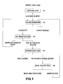
- Fig. 1 illustrates an example of a flowchart of the hydrometallurgical method using high-temperature and high-pressure acid leaching of nickel oxide ore.
- the hydrometallurgical method for nickel oxide ore comprises: a leaching step S1 wherein sulfuric acid is added to a slurry of nickel oxide ore and the slurry is leached under high temperature and high pressure; a solid-liquid separation step S2 wherein multistage washing is applied to a leached slurry to separate a residue, whereby a leachate containing an impurity element as well as nickel and cobalt is obtained; a neutralization step S3 wherein the pH of the leachate is adjusted to separate a neutralized precipitate containing an impurity element therefrom, whereby a post-neutralization solution containing zinc as well as nickel and cobalt is obtained; a dezincification step S4 wherein hydrogen sulfide gas is added to the post-neutralization solution thereby to form zinc sulfide
- the leaching step S 1 for example, using high-temperature and high-pressure leaching, sulfuric acid is added to an ore slurry obtained by pulverizing a nickel oxide ore serving as a raw material, whereby a leached slurry is obtained.
- a high temperature pressurizing vessel autoclave
- the ore slurry is stirred by pressurization under a high temperature of 220 to 280 degrees C, whereby a leached slurry comprising a leachate and a leach residue is formed.
- Laterite ore such as limonite ore or saprolite ore
- the nickel content of laterite ore is usually 0.8 to 2.5% by weight, and the nickel is contained as a hydroxide or a magnesium silicate mineral.
- the iron content of laterite ore is 10 to 50 % by weight, and the iron is mainly in the form of trivalent hydroxide (goethite), but, divalent iron is partially contained in the magnesium silicate mineral.
- oxide ore containing valuable metals, such as nickel, cobalt, manganese, and copper for example, manganese lump present in the deep seabed is used in the leaching step S 1.
- leaching step S 1 leaching reactions and high-temperature hydrolysis reactions which are represented by the following formulas (1) to (5) are caused, whereby sulfate containing nickel, cobalt, or the like is leached out and leached-out iron sulfate is fixed as hematite. It should be noted that, since the fixation of iron ions does not completely proceed, divalent and trivalent iron ions as well as nickel, cobalt, and the like are usually contained in a liquid portion of the obtained leached slurry.
- the amount of sulfuric acid added in the leaching step S1 is not particularly limited, but an excessive amount enough to leach iron contained in the ore is employed. For example, 300 to 400 kg of sulfuric acid is added per ton of ore. If the amount of sulfuric acid added per ton of ore exceeds 400 kg, sulfuric acid cost becomes higher, which is not preferable.
- the leached slurry is mixed with a washing liquid, and then solid-liquid is separated by using a solid-liquid separation apparatus, such as a thickening apparatus.
- a solid-liquid separation apparatus such as a thickening apparatus.
- the slurry is diluted by a washing liquid, and then, the leach residue is condensed as a precipitate in a thickening apparatus.
- the amount of nickel adhering to the leach residue can be decreased depending on the degree of the dilution.
- thickening apparatuses having such function are multistage-connected and used, thereby improving a recovery rate.
- the multistage washing in the solid-liquid separation step S2 is not particularly limited, but there is preferably used a counter current decantation method (CCD method) to bring a washing liquid containing no nickel into contact with a counter current.
- CCD method counter current decantation method
- the washing liquid is not particularly limited, and a washing liquid which does not contain nickel and does not affect the step may be used.
- a washing liquid having a pH of 1 to 3 is preferable. This is because, in the case where aluminum is contained in a leachate, a high pH of a washing liquid causes a large amount of aluminum hydroxide to be formed, thereby leading to poor sedimentation of a leach residue inside a thickening apparatus.
- a barren solution obtained by the nickel recovery step S5 as a following step and having a low pH (pH of approximately 1 to 3) is preferably repeatedly used.
- the pH of the leachate separated in the solid-liquid separation step S2 is adjusted to separate a neutralized precipitate containing an impurity element therefrom, whereby a post-neutralization solution containing zinc as well as nickel and cobalt is obtained.
- a neutralizer such as calcium carbonate is added to said leachate so that a post-neutralization solution obtained has a pH of not more than 4, whereby the post-neutralization solution to serve as a mother liquor for nickel recover and a neutralized precipitate slurry containing trivalent iron as an impurity element are formed.
- Such neutralization of the leachate in the neutralization step S3 allows excessive acid used in the leaching step S1 by high temperature and high pressure acid leaching to be neutralized, whereby a post-neutralization solution to serve as a mother liquor for nickel recovery is formed while trivalent iron ions, aluminum ions, and the like, which remain in the solution, are removed as neutralized precipitates.
- Fig. 2 illustrates a schematic diagram showing a configuration of a neutralization plant.
- a neutralization plant 10 comprises a neutralization reaction tank 11 configured to perform a neutralization reaction, a separation treatment tank 12 configured to separate into a neutralized precipitate and a post-neutralization solution, a storage tank 13 configured to temporarily store the separated post-neutralization solution, and a viscosity measurement portion 14 configured to measure the viscosity of the post-neutralization solution.
- the leachate separated in the above-mentioned solid-liquid separation step S2 is fed into the neutralization reaction tank 11, and a neutralizer is added to said leachate thereby to perform a neutralization reaction.
- the separation treatment tank 12 is a solid-liquid separation apparatus, such as a thickening apparatus.
- a post-neutralization-reaction slurry formed by the neutralization reaction of the leachate in the neutralization reaction tank 11 is transferred and fed into said separation treatment tank 12 , and said slurry is separated into a post-neutralization solution which is to serve as a mother liquor for nickel recovery and a neutralized precipitate slurry containing trivalent iron as an impurity element.
- the post-neutralization solution obtained by the solid-liquid separation overflows to be transferred to a storage tank, meanwhile the neutralized precipitate slurry is extracted from the bottom of the separation treatment tank 12.
- the neutralized precipitate slurry extracted from the bottom of the separation treatment tank 12 can be suitably repeatedly returned to the solid-liquid separation step S2.
- the storage tank 13 is configured so that the post-neutralization solution separated in the separation treatment tank 12 and transferred is fed thereinto, and the post-neutralization solution is temporarily stored before being transferred to the dezincification step S4, which follows the neutralization step S3.
- the storage tank 13, whose details will be described later, acts as a viscosity adjustment buffer capable of reducing the viscosity of the post-neutralization solution obtained by the solid-liquid separation in the separation treatment tank 12.
- the storage tank 13 is not particularly limited, but a storage tank having a volume equivalent to not less than 3-hour's reserve volume with respect to the flow rate of the post-neutralization solution is preferable. Such storage tank allows a residence time of the post-neutralization solution in the storage tank 13 to be longer and the post-neutralization solution to effectively stay therein.
- flow piping 15 configured to send the stored post-neutralization solution to the dezincification step S4, which follows the neutralization step S3.
- the flow piping 15 is to transport the post-neutralization solution stored in the storage tank 13 by a flow pump 16.
- the flow piping 15 is branched at a predetermined point 17 wherein transfer piping 18 and circulation piping 19 each are coupled thereto, the transfer piping 18 being configured to transfer the post-neutralization solution stored in the storage tank 13 to a dezincification reaction tank 31 for a dezincification treatment of the next step, while the circulation piping 19 being configured to repeatedly return the post-neutralization solution to the neutralization reaction tank 11 thereby to circulate the post-neutralization solution.
- a switching valve 20 is installed at the branch point 17 wherein the transfer piping 18 and the circulation piping 19 are coupled, whereby the ratio of the post-neutralization solution transferred via the flow piping 15 can be adjusted by switching.
- a method for transporting the post-neutralization solution from the storage tank 13 via the flow piping 15 will be explained in detail later.
- a heat exchanger is installed in the circulation piping 19 coupled to the flow piping 15, whereby, as will be described in detail later, the post-neutralization solution which is circulated to the neutralization reaction tank 11 at a predetermined quantity ratio can be heated.
- the viscosity measurement portion 14 is to measure the viscosity of the post-neutralization solution separated in the separation treatment tank 12 and transferred to the storage tank 13.
- the viscosity measurement portion 14 is not particularly limited, but, for example, a granulometer or the like may be installed in piping, a flow path, or the like, on the way from the overflow of the post-neutralization solution from the separation treatment tank 12 to the transfer thereof to the storage tank 13.
- a granulometer, a particle size measuring apparatus, or the like may be integrally installed in the separation treatment tank 12 thereby to measure the viscosity of the post-neutralization solution, which is supernatant liquid after the solid-liquid separation in the separation treatment tank 12.
- the viscosity measurement portion 14 may be configured to measure the viscosity of the post-neutralization solution temporarily stored in the storage tank 13.
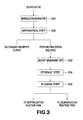
- Fig. 3 illustrates an example of a flowchart of the neutralization method in the neutralization step S3.
- the neutralization method comprises: a neutralization reaction step S31 of performing a neutralization reaction, in the neutralization reaction tank 11, of a leachate obtained through the solid-liquid separation step S2; a separation step S32 of adding a flocculant to a slurry obtained after the neutralization reaction in the separation treatment tank 12, thereby separating into a neutralized precipitate and a post-neutralization solution; a viscosity measurement step S33 of measuring the viscosity of the post-neutralization solution obtained through the separation step S32 in the viscosity measurement portion 14; a storage step S34 of temporarily storing the post-neutralization solution in the storage tank 13; and a flowing step S35 of transporting the stored post-neutralization solution.
- a neutralization reaction is performed in the neutralization reaction tank 11 of the above-mentioned neutralization plant 10 by adding a neutralizer to the leachate fed in.
- a neutralizer such as calcium carbonate is added to said leachate so that a post-neutralization solution obtained has a pH of not more than 4, whereby the post-neutralization solution to serve as a mother liquor for nickel recover and a neutralized precipitate slurry containing trivalent iron are formed.
- a neutralizer is added to the leachate so that the pH of the post-neutralization solution is adjusted to not more than 4, preferably 3.0 to 3.5, more preferably 3.1 to 3.2.
- the post-neutralization solution has a pH of more than 4, a larger amount of nickel hydroxide is formed.
- a suspended solid comprising a neutralized precipitate and a leach residue obtained in the leaching step S1 is preferably made to remain in the post-neutralization solution so that said post-neutralization solution (sulfurization starting solution), which is to be transferred to a dezincification reaction tank 31 for the dezincification step S4 following the neutralization step S3, has a turbidity of 100 to 400 NTU.
- the suspended solid is made to remain, thereby adjusting the turbidity of the post-neutralization solution to the above-mentioned range, whereby the filterability of dezincification sulfide to be formed in the dezincification step S4 as the next step can be further improved.
- the temperature of the neutralization reaction in the neutralization reaction step S31 is preferably 50 to 80 degrees C.
- the reaction temperature is less than 50 degrees C, the neutralized precipitate containing trivalent iron ions to be formed becomes minute, whereby an adverse effect is brought in the solid-liquid separation step S2 wherein the neutralized precipitate is circulated as needed.
- the reaction temperature is more than 80 degrees C, a decrease in corrosion resistance of apparatus materials constituting the neutralization reaction tank 11 and an increase in energy cost for heating are caused.
- the separation step S32 in the separation treatment tank 12 of the above-mentioned neutralization plant 10, the post-neutralization-reaction slurry obtained through the neutralization reaction step S31 is separated into a post-neutralization solution to serve as a mother liquor for nickel recovery and a neutralized precipitate containing an impurity element.
- a flocculant is added to the post-neutralization-reaction slurry, whereby the slurry it separated into the post-neutralization solution and the neutralized precipitate.
- the flocculant for example, an anionic flocculant is used.
- SS minute floating precipitate
- the separated neutralized precipitate slurry may be repeatedly transferred to the above-mentioned solid-liquid separation step S2 as needed.
- nickel contained in the neutralized precipitate slurry can be effectively recovered.
- the neutralized precipitate slurry is repeatedly transferred to the solid-liquid separation step S2 operated under a low pH condition, whereby the leach residue is washed, and at the same time, the dissolution of nickel hydroxide formed by a local reaction between the neutralized precipitate and water adhering thereto on the surface of the neutralized precipitate is promoted, and thus the amount of nickel to be recovery loss can be reduced.
- the operation of repeatedly transferring the separated neutralized precipitate slurry to the solid-liquid separation step S2 can be made to be performed only when the viscosity of the post-neutralization solution is judged to be larger than a predetermined value.
- a post-neutralization solution with high viscosity can be prevented from being transferred to a dezincification plant 30 used in the dezincification step S4 as the next step, whereby the filterability in solid-liquid separation in the dezincification step S4 can be improved.
- the viscosity of the post-neutralization solution obtained through the separation step S32 is measured in the viscosity measurement portion 14 of the above-mentioned neutralization plant 10.
- the viscosity measurement of the post-neutralization solution is performed, for example, by measuring the viscosity of supernatant liquid (overflow liquid) in the separation treatment tank 12.
- Another aspect of the viscosity measurement may be such that, with this viscosity measurement step being arranged as a following step of the storage step, the viscosity of a post-neutralization solution temporarily stored in the storage tank 13 is measured.
- the viscosity measuring method in the viscosity measurement step S33 is not particularly limited as long as the method is capable of measuring the viscosity of a post-neutralization solution in the form of fluid, and a well-known method may be employed, but, from a viewpoint of operation management, a simplified and short-time method is preferable. Furthermore, it may be beneficial that, without calculating a specific viscosity value of a post-neutralization solution, the viscosity thereof is analyzed by calculating an alternative characteristic of the viscosity.
- a method wherein, for example, the time required for a post-neutralization solution to pass through a predetermined filter is measured, and this pass-through time is regarded as an alternative characteristic of the viscosity of the post-neutralization solution and controlled.
- the present embodiment employs a method for viscosity evaluation wherein the time (sec/cm 2 ⁇ mL) required for 50mL of a post-neutralization solution (supernatant liquid) to pass through a membrane filter having an opening of 0.45 ⁇ m is used for viscosity measurement.
- the viscosity of the post-neutralization solution measured in this viscosity measurement step S33 is more than 0.10 sec/cm 2 ⁇ mL. Then, the transfer of the post-neutralization solution is controlled based on the measurement results of the viscosity. The details will be mentioned later.
- the post-neutralization solution obtained by the separation in the separation step S32 and having undergone the viscosity measurement in the viscosity measurement step S33 is temporarily stored in the storage tank 13 of the above-mentioned neutralization plant 10.
- the post-neutralization solution stored in the storage tank 13 in the storage step S34 is flowed.
- the post-neutralization solution stored in the storage tank 13 is transferred to the dezincification reaction tank 31 in the dezincification step S4 following the neutralization step S3.
- the transfer of the post-neutralization solution to the dezincification reaction tank 31 is performed via the flow piping 15 installed in the storage tank 13 and then by making the post-neutralization solution pass through the transfer piping coupled to the flow piping 15.
- the flow rate of the post-neutralization solution transferred via the flow piping 15 and the transfer piping 18 coupled to said flow piping 15 is controlled and, the post-neutralization solution is returned at a predetermined quantity ratio to the neutralization reaction tank 11 via the circulation piping 19 branched from and coupled to the flow piping 15, and circulated.
- the neutralization step S3 of the prior arts when a slurry obtained by neutralizing a leachate is solid-liquid separated into a post-neutralization solution and a neutralized precipitate, a flocculant is added to the slurry.
- the amount of SS can be reduced and also the post-neutralization solution and the neutralized precipitate can be effectively separated.
- the flocculant leads the viscosity of the obtained post-neutralization solution to be very high.
- a sulfurization treatment is applied to the post-neutralization solution transferred from the neutralization step S3, and, in the case where a post-neutralization solution with high viscosity is used here, at the time of solid-liquid separation of a dezincification sulfide precipitate formed by the sulfurization treatment and a mother liquor for nickel recovery, a filter cloth is clogged up, whereby filtration velocity is remarkably reduced. Furthermore, the filter cloth clogging up causes the number of times of washing or the like to be increased, thereby reducing operation efficiency, and also causing the lifespan of the filter cloth to be shortened.
- the viscosity of the post-neutralization solution obtained through the neutralization treatment in the viscosity measurement step S33 is measured, and then it is judged whether or not the measured viscosity is more than a predetermined value. Specifically, a judgment is made using whether or not the time (sec/cm 2 ⁇ mL) required for 50 mL of the post-neutralization solution to pass through a membrane filter having an opening of 0.45 ⁇ m is more than 0.10 sec/cm 2 ⁇ mL, as a viscosity criterion of a post-neutralization solution.
- the flow rate of the post-neutralization solution to be transferred to the dezincification reaction tank 31 in the dezincification step S4 is controlled, whereby the post-neutralization solution is made to be returned to the neutralization reaction tank 11 at a predetermined quantity ratio and circulated.
- the flow rate ratio of the post-neutralization solution to be controlled in the flowing step S35 is not particularly limited.
- a specific flow rate ratio may be determined depending on the level of the viscosity of a post-neutralization solution measured in the viscosity measurement step S33, or the like, but, it is preferable that the flow rate of a post-neutralization solution to pass through the transfer piping 18 via the flow piping 15 and transfer to the dezincification reaction tank 31 is set to 60% to 80% of the full flow, meanwhile the flow rate of a post-neutralization solution to pass through the circulation piping 19 via the flow piping 15 and return to the neutralization reaction tank to circulate is set to 20% to 40% of the full flow.
- the flow rate of a post-neutralization solution to be transferred to the dezincification reaction tank 31 in the next step is controlled based on the result of viscosity measurement of the post-neutralization solution, and the post-neutralization solution is repeatedly returned to the neutralization reaction tank 11 at a predetermined quantity ratio and circulated, whereby a post-neutralization solution with high viscosity can be prevented from being transferred to the dezincification reaction tank 31.
- the post-neutralization solution obtained from the separation treatment tank 12 through the separation step S32 is temporarily stored in the storage tank 13 in the storage step S34.
- the separated post-neutralization solution is thus temporarily stored in the storage tank 13 without being directly transferred to the dezincification reaction tank 31 of the next step, whereby the post-neutralization solution can stay in the storage tank 13.
- a post-neutralization solution having a high viscosity and returned to the neutralization reaction tank 11 at a predetermined flow rate ratio and circulated is made to stay in the storage tank 13, and the post-neutralization solution is mixed in proportion to the residence time, and therefore the viscosity thereof is effectively reduced. That is, the storage tank 13 which stores a post-neutralization solution in the storage step S34 acts as a buffer in terms of viscosity.
- a post-neutralization solution is returned to the neutralization reaction tank 11 at a predetermined quantity ratio and circulated in the flowing step S35, addition of a flocculant in the separation step S32 is preferably stopped.
- a post-neutralization solution with high viscosity is circulated at a predetermined quantity ratio, if the addition of a flocculant in the separation step S32 is stopped, a post-neutralization solution obtained through the neutralization reaction step S31 and the separation step S32 is made to contain only a flocculant derived from the returned post-neutralization solution.
- the transfer of the post-neutralization solution, the cloudy overflow liquid, to the dezincification step S4 causes a filter cloth to be clogged up at the time of separation of zinc sulfide and a mother liquor for nickel recovery, whereby a fault of shortening the lifespan of a filter cloth might be rather caused.
- a post-neutralization solution is temporarily stored using the storage tank 13 in the storage step S34, and the time for a post-neutralization solution to stay in the storage tank 13 is secured, and therefore most of a neutralized precipitate as a cause of the cloudiness precipitates at the bottom of the storage tank 13.
- the neutralized precipitate as a cause of the cloudiness can be prevented from being transferred to the dezincification step S4, whereby the above-mentioned fault is not caused.
- the amount of a flocculant to be added may be adjusted based on the flow rate of the post-neutralization solution to be circulated.
- the total amount of a flocculant contained in a post-neutralization solution is "(amount of a flocculant newly added) + (amount of a flocculant in a circulated post-neutralization solution)".
- the amount of a flocculant newly added may be adjusted to be equivalent to 1/2 or 1/3 of a usual amount.
- a reduction in aggregation effect in the separation step S32 can be inhibited, and in addition, the viscosity of a post-neutralization solution can be reduced.
- Such adjustment of the amount of a flocculant added can be more easily performed by the calculation of the amount of a flocculant contained in a circulated post-neutralization solution.
- the post-neutralization solution is returned to the neutralization reaction tank 11 at a predetermined quantity ratio and circulated, based on the length of the residence time gained in proportion to the volume of the storage tank 13, it may be selected whether addition of a flocculant in the separation step S32 is stopped or the amount of an flocculant to be added is adjusted. That is, in the case where the volume of the storage tank 13 is large enough to gain a sufficient residence time, it is beneficial to choose the method of adjusting the amount of a flocculant to be added.
- the flow rate of the post-neutralization solution transferred to the dezincification reaction tank 31 in the flowing step S35 is controlled, and the post-neutralization solution is returned to the neutralization reaction tank 11 at a predetermined quantity ratio and circulated.
- the viscosity of a post-neutralization solution to overflow the separation treatment tank 12 in the separation step S32 can be gradually reduced.
- the viscosity of a post-neutralization solution stored in the storage tank 13 continues to be similarly adjusted, and, when the viscosity thereof is sufficiently reduced and reaches not more than a predetermined viscosity, the switching valve 20 installed in the flow piping 15 is adjusted in the flowing step S35, whereby the post-neutralization solution stored in the storage tank 13 is transferred to the dezincification reaction tank 31 of the next step, the dezincification step S4.
- the amount of a flocculant to be added in the separation step S32 is reset to an usual amount.
- Such control of the neutralization treatment in the neutralization step S3 can prevent a post-neutralization solution with high viscosity from being transferred to the dezincification step S4 as the next step, whereby filterability at the time of the separation of zinc sulfide formed in the dezincification step S4 can be improved. Furthermore, clogging of a filter cloth is thus controlled and the lifespan of the filter cloth can be extended. Moreover, the control of clogging of a filter cloth allows the frequency of filter cloth washing operation to be effectively reduced, whereby efficient operation, including in terms of costs, is achieved. Specifically, the frequency of filter cloth washing operation can be reduced to approximately half the frequency thereof in the prior arts, while the lifespan of a filter cloth can be extended approximately 4 times the lifespan thereof in the prior arts.
- the viscosity of a measured post-neutralization solution is more than 0.5 sec/cm 2 ⁇ mL on the basis of the above-mentioned viscosity criterion, it implies that said post-neutralization solution has a too high viscosity. If such post-neutralization solution is transferred to the dezincification plant 31 and made to undergo the dezincification step S4, the filterability in solid-liquid separation is considerably impaired.
- the viscosity of a measured post-neutralization solution is more than 0.5 sec/cm 2 ⁇ mL on the basis of the above-mentioned viscosity criterion
- an operation of making a neutralized precipitate slurry repeatedly undergo the solid-liquid separation step S2 is performed.
- the viscosity of the post-neutralization solution can be more effectively reduced.
- dezincification step S4 hydrogen sulfide gas is added to a post-neutralization solution obtained through the neutralization step S3 thereby to form zinc sulfide, and said zinc sulfide is separated therefrom to obtain a mother liquor for nickel recovery (post-dezincification solution), the mother liquor containing nickel and cobalt.
- a post-neutralization solution containing zinc as well as nickel and cobalt is fed into a pressurized container, and hydrogen sulfide gas is blown into a gas phase thereof, whereby zinc is selectively sulfurized with respect to nickel and cobalt, and thus, zinc sulfide and a mother liquor for nickel recovery are formed.
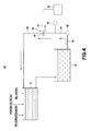
- a dezincification plant 30 comprises: a dezincification reaction tank 31 configured to blow hydrogen sulfide gas into a post-neutralization solution to perform a sulfurization reaction; a storage tank 32 configured to temporarily store a formed zinc sulfide and a mother liquor for nickel recovery serving as a post-sulfurization solution; and a filter apparatus 33 configured to separate and remove the zinc sulfide.
- a post-neutralization solution obtained through the above-mentioned neutralization step S3 and transferred is fed into the dezincification reaction tank 31, and hydrogen sulfide gas is added to the post-neutralization solution to perform a sulfurization reaction.
- the addition of hydrogen sulfide gas allows the formation of zinc sulfide based on zinc contained in the post-neutralization solution.
- a solution obtained after the sulfurization treatment in the dezincification reaction tank 31 does not contain zinc and serves as a mother liquor for nickel recovery.
- the storage tank 32 is configured that the zinc sulfide obtained in the dezincification reaction tank 31 and the mother liquor for nickel recovery, which is a post-sulfurization solution, are fed thereinto.
- the zinc sulfide and the mother liquor for nickel recovery are temporarily stored before the zinc sulfide and the mother liquor for nickel recovery are separated and the mother liquor for nickel recovery is transferred to the nickel recovery step S5 following the dezincification step S4.
- the post-neutralization solution transported without undergoing a sulfurization treatment in the dezincification reaction tank 31 is stored in the storage tank 32 at the time of the start-up of the dezincification plant 30.
- flow piping 34 configured to transport zinc sulfide and the mother liquor for nickel recovery, each being stored therein, is installed.
- the flow piping 34 transports the zinc sulfide and the mother liquor for nickel recovery, each being stored in the storage tank 32, to the filter apparatus 33, using a flow pump 35.
- the flow piping 34 branches out at a predetermined point 36, and transfer piping 37 configured to transfer the mother liquor for nickel recovery, containing zinc sulfide and being stored in the storage tank 32, to the filter apparatus 33 and circulation piping 38 configured to repeatedly return a post-neutralization solution stored in the storage tank 32 to the (dezincification reaction tank 31 and circulate said post-neutralization solution at the time of the start-up of the dezincification plant 30 each are coupled to the flow piping 34.
- a switching valve 39 is installed at the branch point 36 (coupling portion) in which the transfer piping 37 and the circulation piping 38 each are coupled, whereby the quantity ratio and timing of the transfer to the filter apparatus 33 or the dezincification reaction tank 31 via the flow piping 34 can be switched and adjusted. Furthermore, in the flow piping 34, there is provided a measurement portion 40 capable of measuring the flow rate and/or the temperature of a zinc-sulfide-containing transported mother liquor for nickel recovery or a circulated post-neutralization solution.
- the filter apparatus 33 is composed of a filter cloth having a predetermined opening, and the like, and separates zinc sulfide and a mother liquor for nickel recovery from a zinc-sulfide-containing mother liquor for nickel recovery transported through the transfer piping 37 via the flow piping 34.
- the flow rate of the post-neutralization solution to be transferred to the dezincification reaction tank 31 of the dezincification plant 30 is controlled, and therefore the post-neutralization solution with high viscosity is effectively prevented from being transferred to the dezincification plant 30.
- the filter apparatus 33 in the dezincification plant 30 clogging of a filter cloth is reduced, whereby zinc sulfide can be separated and removed with high filterability.
- the lifespan of the filter cloth can be extended and operation efficiency of hydrometallurgy can be improved.
- a periodic inspection for equipment is conducted.
- process water such as a reaction tank and a storage tank, piping, filters, and the like
- process water such as a post-neutralization solution and a post-dezincification solution
- Such unstable state of the flow rate and the temperature particularly greatly affects the dezincification step S4, and it is very difficult to blow hydrogen sulfide gas into the process water having a temperature and a flow rate in an unstable state, that is, a post-neutralization solution to be subject to a sulfurization treatment, and simultaneously add a suspended solid as a seed crystal thereto.
- an unstable state that is, a post-neutralization solution to be subject to a sulfurization treatment, and simultaneously add a suspended solid as a seed crystal thereto.
- zinc, an impurity, of high concentration is unwillingly mixed into a solution (a mother liquor for nickel recovery) obtained after a dezincification reaction by sulfurization.
- the switching valve 39 in the flow piping 34 installed in the storage tank 32 is adjusted, whereby the transferred post-neutralization solution is controlled to be returned to the dezincification reaction tank 31 via the circulation piping 38 and circulated.
- the flow rate and/or the temperature of a post-neutralization solution circulated is measured at the measurement portion 40 installed in the flow piping 34, and, when the flow rate and/or the temperature of said post-neutralization solution reaches a predetermined value or more, a sulfurization treatment is applied to the post-neutralization solution in the dezincification reaction tank 31 thereby to form zinc sulfide, and a mother liquor for nickel recovery containing said zinc sulfide (post-dezincification solution) is transferred to the filter apparatus 33 via the transfer piping 37 by adjusting the switching valve 39.
- a predetermined standard value of the flow rate of a circulated post-neutralization solution measured in the measurement portion 40 is not particularly limited, and it is beneficial that whether or not the flow rate thereof allows a sulfurization reaction in the dezincification reaction tank 31 to effectively proceed is set at the standard, and for example, the flow rate value at the time of usual operation can be regarded as the standard.
- a predetermined standard value of the temperature of a circulated post-neutralization solution measured in the measurement portion 40 is not particularly limited, and it is beneficial that the standard is whether or not the temperature thereof allows a sulfurization reaction in the dezincification reaction tank 31 to effectively proceed is set at the standard, and for example, a temperature of approximately 50 degrees C can be regarded as the standard.
- a post-neutralization solution is controlled to be circulated and it is judged whether or not the flow rate and the temperature of said post-neutralization solution reach, for example, a flow rate at a usual operation and a temperature of approximately not less than 50 degrees C, respectively. Then, when it is confirmed that the flow rate and the temperature of the post-neutralization solution reach the predetermined value or more, a sulfurization treatment is applied to the post-neutralization solution, and a zinc-sulfide-containing mother liquor for nickel recovery is transferred to the filter apparatus 33.
- the flow rate control of a post-neutralization solution in the neutralization plant 10 used in the neutralization step S3 is also performed.
- the switching valve 20 installed in the flow piping 15 of the neutralization plant 10 is adjusted, whereby a post-neutralization solution is controlled to be returned to the neutralization reaction tank 11 and circulated.
- a post-neutralization solution is made to circulate in the neutralization treatment plant 10.
- the switching valve 20 is adjusted so as to transfer the post-neutralization solution to the dezincification reaction tank 31 via the transfer piping 18.
- a post-neutralization solution returned to the neutralization reaction tank 11 in the neutralization plant 10 and circulated is preferably circulated while being warmed.
- a heat exchanger installed in the circulation piping 19 of the neutralization plant 10 may be used for heating.
- the flow rate control of a post-neutralization solution in the neutralization plant 10 is performed, whereby plant operation can be stabilized in a shorter time after the start-up thereof.
- a sulfurization treatment in the dezincification plant 30 effectively proceeds, and therefore the concentration of zinc contained in a mother liquor for nickel recovery can be reduced more effectively.
- a post-neutralization solution to be circulated in the neutralization plant 10 is circulated while being heated, whereby the temperature of the post-neutralization solution in the neutralization plant 10 is made higher, and the post-neutralization solution transferred to the dezincification reaction tank 31 can be more efficiently heated.
- the operation can be stabilized in a further shorter time, and the concentration of zinc in a mother liquor for nickel recovery can be effectively reduced.
- the nickel recovery step S5 hydrogen sulfide gas is blown into a mother liquor for nickel recovery to induce a sulfurization reaction, the mother liquor being obtained by separating and removing zinc, an impurity element, in the form of zinc sulfide in the dezincification step S4, whereby a sulfide containing nickel and cobalt (a nickel-cobalt mixed sulfide) and a barren solution are formed.
- the mother liquor for nickel recovery is a sulfuric acid solution, which is obtained from a leachate of nickel oxide ore by reducing an impurity component in the leachate via the neutralization step S3 and the dezincification step S4, and for example, the mother liquor has a pH of 3.2 to 4.0, a nickel concentration of 2 to 5 g/L, and a cobalt concentration of 0.1 to 1.0 g/L.
- a nickel-cobalt mixed sulfide containing less impurity component and a barren solution in which the concentration of nickel is stabilized at a low level are formed and recovered.
- a slurry of nickel-cobalt mixed sulfide obtained by a sulfurization reaction undergoes sedimentation using a precipitator, such as a thickening apparatus, whereby a nickel-cobalt mixed sulfide as a precipitate is separated and recovered from the bottom of the thickening apparatus.
- a precipitator such as a thickening apparatus
- an aqueous solution component is made to overflow, thereby being recovered as a barren solution.
- this barren solution contains unsulfurized impurity elements of iron, magnesium, manganese, and the like.
- each of the plants was started up, and, in a dezincification plant, the following operation was performed in a dezincification treatment step at the time of the start-up thereof. It should be noted that the temperatures of the plant and process water at the time of the start-up were 30 degrees C.
- a switching valve in flow piping installed in a storage tank is adjusted, whereby simultaneously a part of said post-neutralization solution was circulated to a neutralization reaction tank via circulation piping coupled to the flow piping.
- the post-neutralization solution circulated was heated using a heat exchanger installed in the circulation piping.
- the switching valve was adjusted to stop heat-circulation of the post-neutralization solution to the neutralization reaction tank in the neutralization plant, whereby the whole amount of the post-neutralization solution was transferred to the dezincification reaction tank.
- the temperature of the post-neutralization solution transferred to the dezincification reaction tank rose to 40 degrees C from 30 degrees C, the temperature at the time of starting the start-up.
- the reason why the flow rate of the mother liquor for nickel recovery reached the designated value in a shorter time than in Example 1 may be that, not only the circulation of a post-neutralization solution in the dezincification plant, but also the heat-circulation of a post-neutralization solution in the neutralization plant were performed, thereby allowing the temperature of the post-neutralization solution in the neutralization plant to be higher and the temperature of the post-neutralization solution transferred to the dezincification reaction tank to rise more quickly, whereby the dezincification reaction was more efficiently and promptly stabilized.
- the concentration of zinc in a mother liquor for nickel recovery (post-dezincification solution) supplied to a sulfurization reaction tank in a nickel recovery step, following the dezincification step, was 0.5 mg/L on average, which satisfied an upper control limit of 1 mg/L.
- the zinc grade of a nickel-cobalt mixed sulfide formed in the nickel recovery step to which the mother liquor for nickel recovery had been transferred was measured, and as a result, the zinc grade was found to be 0.007% by weight, which satisfied a specification upper limit of 0.020% by weight.
- Example 3 another periodic inspection, which was different from the above-mentioned inspections performed in Examples 1 and 2, was performed for metallurgical plants for leaching of nickel oxide ore over one week, and then the same operation as in Example 2 was performed at the time of the start-up of each of the plants. It should be noted that the temperatures of the plants and process water at the time of the start-up thereof were 25 degrees C.
- Example 3 when it was confirmed that the temperature of the post-neutralization solution circulated to the dezincification reaction tank in the dezincification plant reached 60 degrees C, also a switching valve was also adjusted to stop heat-circulation of the post-neutralization solution to the neutralization reaction tank in the neutralization plant, whereby the whole amount of the post-neutralization solution was transferred to the dezincification reaction tank. At this time, the temperature of the post-neutralization solution transferred to the dezincification reaction tank rose to 35 degrees C from 20 degrees C, the temperature at the time of starting the start-up.
- Comparative Example 1 a plant not equipped with circulation piping was used.
- the same periodic inspection as in Examples 1 and 2 was performed for metallurgical plants for leaching over one week.
- a post-neutralization solution was made to undergo a sulfurization treatment (dezincification reaction) of blowing hydrogen sulfide gas in a dezincification reaction tank from the time of starting the start-up, whereby a dezincificated sulfide was formed, and an operation wherein a zinc-sulfide-containing mother liquor for nickel recovery was transferred to a filter apparatus thereby to separate and remove the zinc sulfide was performed.
- the temperature of the post-neutralization solution transferred to the dezincification reaction tank at the time of the start-up was 30 degrees C, which was extremely lower than a lower control limit of 55 degrees C.
- the concentration of zinc in a mother liquor for nickel recovery (post-dezincification solution) supplied to a sulfurization reaction tank in the nickel recovery step, following the dezincification step, during the 24 hours that elapsed before the flow rate of the mother liquor for nickel recovery reached a designated value was 12.4 mg/L on average, which was considerably higher than an upper control limit of 1 mg/L.
- the zinc grade of a nickel-cobalt mixed sulfide formed in the nickel recovery step to which the mother liquor for nickel recovery had been transferred was measured, and as a result, the zinc grade was found to be 0.148% by weight on average, which was greatly higher than a specification upper limit of 0.020% by weight. Therefore, all of the lots concerned were regarded as nonconforming items.
- Comparative Example 2 a plant not equipped with circulation piping was used.
- the same periodic inspection as in Example 3 was performed for metallurgical plants for leaching over one week.
- a post-neutralization solution was made to undergo a sulfurization treatment (dezincification reaction) of blowing hydrogen sulfide gas in a dezincification reaction tank from the time of starting the start-up, whereby a dezincificated sulfide was formed, and an operation wherein a zinc-sulfide-containing mother liquor for nickel recovery was transferred to a filter apparatus thereby to separate and remove the zinc sulfide was performed.
- the temperature of the post-neutralization solution transferred to the dezincification reaction tank at the time of the start-up was 30 degrees C, which was extremely lower than a lower control limit of 55 degrees C.
- the concentration of zinc in a mother liquor for nickel recovery (post-dezincification solution) supplied to a sulfurization reaction tank in the nickel recovery step, following the dezincification step, during the 39 hours that elapsed before the flow rate of the mother liquor for nickel recovery reached a designated value was 10.2 mg/L on average, which was considerably higher than an upper control limit of 1 mg/L.
- the zinc grade of a nickel-cobalt mixed sulfide formed in the nickel recovery step to which the mother liquor for nickel recovery had been transferred was measured, and as a result, the zinc grade was found to be 0.135% by weight on average, which was greatly higher than a specification upper limit of 0.020% by weight. Therefore, all of the lots concerned were regarded as nonconforming items.
- Comparative Example 3 a plant not equipped with circulation piping was used. In other words, in Comparative Example 3, the same periodic inspection as in Example 3 was performed over one week. Then, in the start-up after the completion of the periodic maintenance inspection, without being circulated in a dezincification plant, a post-neutralization solution was made to undergo a sulfurization treatment (dezincification reaction) of blowing hydrogen sulfide gas in a dezincification reaction tank from the time of starting the start-up, whereby a dezincificated sulfide was formed, and an operation wherein a zinc-sulfide-containing mother liquor for nickel recovery was transferred to a filter apparatus thereby to separate and remove the zinc sulfide was performed.
- a sulfurization treatment dezincification reaction
- the temperature of the post-neutralization solution transferred to the dezincification reaction tank at the time of the start-up was 30 degrees C, which was extremely lower than a lower control limit of 55 degrees C.
- the leachate in the leachate storage tank was transferred to another tank thereby to lower the liquid level of the storage tank, and the leaching treatment plant configured to perform a leaching step was started up, but, the reaction in the dezincification step was not still stabilized yet, and accordingly the dezincification plant configured to perform the dezincification step was forced to be suspended. Therefore, once again, it became impossible to supply the leachate to the neutralization reaction tank in the neutralization step, whereby the liquid volume in the leachate storage tank was increased again, and accordingly a second suspension of the operation of the leaching plant to perform the leaching step was forced.
- the concentration of zinc in a mother liquor for nickel recovery (post-dezincification solution) supplied to a sulfurization reaction tank in the nickel recovery step, following the dezincification step, during the 51 hours that elapsed before the flow rate of the mother liquor for nickel recovery reached a designated value was 13.8 mg/L on average, which was considerably higher than an upper control limit of 1 mg/L.
- the zinc grade of a nickel-cobalt mixed sulfide formed in the nickel recovery step to which the mother liquor for nickel recovery had been transferred was measured, and as a result, the zinc grade was found to be 0.162% by weight on average, which was greatly higher than a specification upper limit of 0.020% by weight. Therefore, all of the lots concerned were regarded as nonconforming items.
- Comparative Example 4 a plant not equipped with circulation piping was used. In other words, in Comparative Example 4, another periodic inspection, which was different from the periodic inspection performed in Examples 1 to 3, was performed over one week. Then, in the start-up after the completion of the periodic inspection, without being circulated in a dezincification plant, a post-neutralization solution was made to undergo a sulfurization treatment (dezincification reaction) of blowing hydrogen sulfide gas in a dezincification reaction tank from the time of starting the start-up, whereby a dezincificated sulfide was formed, and an operation wherein a zinc-sulfide-containing mother liquor for nickel recovery was transferred to a filter apparatus thereby to separate and remove the zinc sulfide was performed.
- a sulfurization treatment dezincification reaction
- the temperature of the post-neutralization solution transferred to the dezincification reaction tank at the time of the start-up was 30 degrees C, which was extremely lower than a lower control limit of 55 degrees C.
- the leaching treatment plant was once started up in order to hurry a leaching treatment, and the supply of the leachate to the neutralization reaction tank in the neutralization step and, in addition, the supply of the post-neutralization solution to the dezincification reaction tank in the dezincification step each were started.
- the concentration of zinc in a mother liquor for nickel recovery (post-dezincification solution) supplied to a sulfurization reaction tank in the nickel recovery step, following the dezincification step was 23.8 mg/L on average, which was considerably higher than an upper control limit of 1 mg/L.
- the zinc grade of a nickel-cobalt mixed sulfide formed in the nickel recovery step to which the mother liquor for nickel recovery had been transferred was measured, and as a result, the zinc grade was found to be 0.280% by weight on average, which was greatly higher than a specification upper limit of 0.020% by weight. Therefore, all of the lots concerned were regarded as nonconforming items.
Landscapes
- Chemical & Material Sciences (AREA)
- Engineering & Computer Science (AREA)
- Mechanical Engineering (AREA)
- Manufacturing & Machinery (AREA)
- Materials Engineering (AREA)
- Metallurgy (AREA)
- Organic Chemistry (AREA)
- Chemical Kinetics & Catalysis (AREA)
- General Chemical & Material Sciences (AREA)
- Geochemistry & Mineralogy (AREA)
- Geology (AREA)
- General Life Sciences & Earth Sciences (AREA)
- Environmental & Geological Engineering (AREA)
- Life Sciences & Earth Sciences (AREA)
- Manufacture And Refinement Of Metals (AREA)
Applications Claiming Priority (2)
| Application Number | Priority Date | Filing Date | Title |
|---|---|---|---|
| JP2012049511A JP5348267B2 (ja) | 2012-03-06 | 2012-03-06 | 脱亜鉛処理プラント及び脱亜鉛プラントの操業方法、並びにニッケル酸化鉱石の湿式製錬方法 |
| PCT/JP2013/055706 WO2013133172A1 (fr) | 2012-03-06 | 2013-03-01 | Installation de dézincification, procédé d'exploitation de l'installation de dézincification et procédé hydrométallurgique destiné à du minerai d'oxyde de nickel |
Publications (3)
| Publication Number | Publication Date |
|---|---|
| EP2824203A1 true EP2824203A1 (fr) | 2015-01-14 |
| EP2824203A4 EP2824203A4 (fr) | 2015-12-02 |
| EP2824203B1 EP2824203B1 (fr) | 2016-09-14 |
Family
ID=49116652
Family Applications (1)
| Application Number | Title | Priority Date | Filing Date |
|---|---|---|---|
| EP13758324.1A Not-in-force EP2824203B1 (fr) | 2012-03-06 | 2013-03-01 | Installation de dézincification, procédé d'exploitation de l'installation de dézincification et procédé hydrométallurgique destiné à du minerai d'oxyde de nickel |
Country Status (6)
| Country | Link |
|---|---|
| US (1) | US9945007B2 (fr) |
| EP (1) | EP2824203B1 (fr) |
| JP (1) | JP5348267B2 (fr) |
| AU (1) | AU2013228541B2 (fr) |
| PH (1) | PH12014501972B1 (fr) |
| WO (1) | WO2013133172A1 (fr) |
Families Citing this family (7)
| Publication number | Priority date | Publication date | Assignee | Title |
|---|---|---|---|---|
| JP4888578B2 (ja) * | 2010-04-15 | 2012-02-29 | 住友金属鉱山株式会社 | ニッケル酸化鉱石の湿式精錬プラント及びその操業方法 |
| PH12021550330A1 (en) * | 2013-08-21 | 2022-09-28 | Janssen Biopharma Inc | Antiviral compounds |
| JP6981206B2 (ja) | 2017-11-24 | 2021-12-15 | 住友金属鉱山株式会社 | 硫酸ニッケル水溶液の脱亜鉛システム、及びその方法 |
| JP6996328B2 (ja) * | 2018-02-14 | 2022-02-04 | 住友金属鉱山株式会社 | 脱亜鉛処理方法、ニッケル酸化鉱石の湿式製錬方法 |
| JP7147452B2 (ja) * | 2018-10-12 | 2022-10-05 | 住友金属鉱山株式会社 | 亜鉛硫化物除去用の濾過設備及びこれを用いたニッケルコバルト混合硫化物の製造方法 |
| JP7322579B2 (ja) * | 2019-08-07 | 2023-08-08 | 住友金属鉱山株式会社 | スラリーの搬送設備及びスラリーの送液方法 |
| JP7310490B2 (ja) * | 2019-09-25 | 2023-07-19 | 住友金属鉱山株式会社 | 中和工程における処理立上げに際しての操業方法 |
Family Cites Families (7)
| Publication number | Priority date | Publication date | Assignee | Title |
|---|---|---|---|---|
| JP3203707B2 (ja) | 1991-10-09 | 2001-08-27 | 大平洋金属株式会社 | 酸化鉱石から有価金属を回収する方法 |
| JP4525428B2 (ja) | 2004-05-13 | 2010-08-18 | 住友金属鉱山株式会社 | ニッケル酸化鉱石の湿式製錬方法 |
| JP5287010B2 (ja) * | 2008-07-31 | 2013-09-11 | 住友金属鉱山株式会社 | ニッケル酸化鉱石の湿式製錬方法 |
| JP5287016B2 (ja) * | 2008-08-07 | 2013-09-11 | 住友金属鉱山株式会社 | 亜鉛硫化物の分離方法 |
| JP5446226B2 (ja) * | 2008-09-19 | 2014-03-19 | 住友金属鉱山株式会社 | ニッケル酸化鉱石の湿式製錬方法 |
| US8911531B2 (en) * | 2009-10-19 | 2014-12-16 | Sumitomo Metal Mining Co., Ltd. | Hydrometallurgical plant of nickel laterite ore and operation method thereof |
| JP4888578B2 (ja) * | 2010-04-15 | 2012-02-29 | 住友金属鉱山株式会社 | ニッケル酸化鉱石の湿式精錬プラント及びその操業方法 |
-
2012
- 2012-03-06 JP JP2012049511A patent/JP5348267B2/ja active Active
-
2013
- 2013-03-01 AU AU2013228541A patent/AU2013228541B2/en not_active Ceased
- 2013-03-01 EP EP13758324.1A patent/EP2824203B1/fr not_active Not-in-force
- 2013-03-01 WO PCT/JP2013/055706 patent/WO2013133172A1/fr not_active Ceased
- 2013-03-01 US US14/382,632 patent/US9945007B2/en not_active Expired - Fee Related
-
2014
- 2014-09-03 PH PH12014501972A patent/PH12014501972B1/en unknown
Also Published As
| Publication number | Publication date |
|---|---|
| JP2013185178A (ja) | 2013-09-19 |
| PH12014501972A1 (en) | 2014-11-17 |
| US9945007B2 (en) | 2018-04-17 |
| JP5348267B2 (ja) | 2013-11-20 |
| WO2013133172A1 (fr) | 2013-09-12 |
| US20150023849A1 (en) | 2015-01-22 |
| EP2824203B1 (fr) | 2016-09-14 |
| EP2824203A4 (fr) | 2015-12-02 |
| PH12014501972B1 (en) | 2014-11-17 |
| AU2013228541B2 (en) | 2016-12-22 |
| AU2013228541A1 (en) | 2014-09-25 |
Similar Documents
| Publication | Publication Date | Title |
|---|---|---|
| EP2824203B1 (fr) | Installation de dézincification, procédé d'exploitation de l'installation de dézincification et procédé hydrométallurgique destiné à du minerai d'oxyde de nickel | |
| JP5435058B2 (ja) | 中和処理方法及び中和処理プラント | |
| EP2975142B1 (fr) | Installation hydrométallurgique pour minerai d'oxyde de nickel et procédé pour la conduite de ladite installation hydrométallurgique | |
| EP2957332B1 (fr) | Procédé de traitement de séparation solide-liquide, et procédé hydrométallurgique pour minerai d'oxyde de nickel | |
| EP2573197A1 (fr) | Procédé permettant de contrôler la réaction dans une étape de réaction de sulfuration | |
| US9751035B2 (en) | Operation method for dezincification plant | |
| AU2007308764A1 (en) | Method for production of metallic cobalt from the nickel solvent extraction raffinate | |
| JP5804147B2 (ja) | ニッケル酸化鉱石の湿式製錬プラント | |
| JP5725143B2 (ja) | 中和処理プラント | |
| JP2015038251A (ja) | 脱亜鉛プラントの操業方法 |
Legal Events
| Date | Code | Title | Description |
|---|---|---|---|
| PUAI | Public reference made under article 153(3) epc to a published international application that has entered the european phase |
Free format text: ORIGINAL CODE: 0009012 |
|
| 17P | Request for examination filed |
Effective date: 20140918 |
|
| AK | Designated contracting states |
Kind code of ref document: A1 Designated state(s): AL AT BE BG CH CY CZ DE DK EE ES FI FR GB GR HR HU IE IS IT LI LT LU LV MC MK MT NL NO PL PT RO RS SE SI SK SM TR |
|
| AX | Request for extension of the european patent |
Extension state: BA ME |
|
| DAX | Request for extension of the european patent (deleted) | ||
| RA4 | Supplementary search report drawn up and despatched (corrected) |
Effective date: 20151029 |
|
| RIC1 | Information provided on ipc code assigned before grant |
Ipc: C22B 3/04 20060101ALI20151023BHEP Ipc: C22B 3/44 20060101ALI20151023BHEP Ipc: C22B 23/00 20060101AFI20151023BHEP Ipc: C22B 9/02 20060101ALI20151023BHEP |
|
| GRAP | Despatch of communication of intention to grant a patent |
Free format text: ORIGINAL CODE: EPIDOSNIGR1 |
|
| INTG | Intention to grant announced |
Effective date: 20160407 |
|
| GRAJ | Information related to disapproval of communication of intention to grant by the applicant or resumption of examination proceedings by the epo deleted |
Free format text: ORIGINAL CODE: EPIDOSDIGR1 |
|
| GRAR | Information related to intention to grant a patent recorded |
Free format text: ORIGINAL CODE: EPIDOSNIGR71 |
|
| GRAS | Grant fee paid |
Free format text: ORIGINAL CODE: EPIDOSNIGR3 |
|
| GRAJ | Information related to disapproval of communication of intention to grant by the applicant or resumption of examination proceedings by the epo deleted |
Free format text: ORIGINAL CODE: EPIDOSDIGR1 |
|
| GRAR | Information related to intention to grant a patent recorded |
Free format text: ORIGINAL CODE: EPIDOSNIGR71 |
|
| GRAS | Grant fee paid |
Free format text: ORIGINAL CODE: EPIDOSNIGR3 |
|
| INTC | Intention to grant announced (deleted) | ||
| GRAA | (expected) grant |
Free format text: ORIGINAL CODE: 0009210 |
|
| INTG | Intention to grant announced |
Effective date: 20160728 |
|
| AK | Designated contracting states |
Kind code of ref document: B1 Designated state(s): AL AT BE BG CH CY CZ DE DK EE ES FI FR GB GR HR HU IE IS IT LI LT LU LV MC MK MT NL NO PL PT RO RS SE SI SK SM TR |
|
| REG | Reference to a national code |
Ref country code: GB Ref legal event code: FG4D |
|
| REG | Reference to a national code |
Ref country code: CH Ref legal event code: EP |
|
| REG | Reference to a national code |
Ref country code: IE Ref legal event code: FG4D |
|
| REG | Reference to a national code |
Ref country code: AT Ref legal event code: REF Ref document number: 829066 Country of ref document: AT Kind code of ref document: T Effective date: 20161015 |
|
| REG | Reference to a national code |
Ref country code: DE Ref legal event code: R096 Ref document number: 602013011654 Country of ref document: DE |
|
| REG | Reference to a national code |
Ref country code: LT Ref legal event code: MG4D |
|
| REG | Reference to a national code |
Ref country code: NL Ref legal event code: MP Effective date: 20160914 |
|
| PG25 | Lapsed in a contracting state [announced via postgrant information from national office to epo] |
Ref country code: NO Free format text: LAPSE BECAUSE OF FAILURE TO SUBMIT A TRANSLATION OF THE DESCRIPTION OR TO PAY THE FEE WITHIN THE PRESCRIBED TIME-LIMIT Effective date: 20161214 Ref country code: LT Free format text: LAPSE BECAUSE OF FAILURE TO SUBMIT A TRANSLATION OF THE DESCRIPTION OR TO PAY THE FEE WITHIN THE PRESCRIBED TIME-LIMIT Effective date: 20160914 Ref country code: FI Free format text: LAPSE BECAUSE OF FAILURE TO SUBMIT A TRANSLATION OF THE DESCRIPTION OR TO PAY THE FEE WITHIN THE PRESCRIBED TIME-LIMIT Effective date: 20160914 Ref country code: HR Free format text: LAPSE BECAUSE OF FAILURE TO SUBMIT A TRANSLATION OF THE DESCRIPTION OR TO PAY THE FEE WITHIN THE PRESCRIBED TIME-LIMIT Effective date: 20160914 Ref country code: RS Free format text: LAPSE BECAUSE OF FAILURE TO SUBMIT A TRANSLATION OF THE DESCRIPTION OR TO PAY THE FEE WITHIN THE PRESCRIBED TIME-LIMIT Effective date: 20160914 |
|
| REG | Reference to a national code |
Ref country code: FR Ref legal event code: PLFP Year of fee payment: 5 |
|
| REG | Reference to a national code |
Ref country code: AT Ref legal event code: MK05 Ref document number: 829066 Country of ref document: AT Kind code of ref document: T Effective date: 20160914 |
|
| PG25 | Lapsed in a contracting state [announced via postgrant information from national office to epo] |
Ref country code: GR Free format text: LAPSE BECAUSE OF FAILURE TO SUBMIT A TRANSLATION OF THE DESCRIPTION OR TO PAY THE FEE WITHIN THE PRESCRIBED TIME-LIMIT Effective date: 20161215 Ref country code: SE Free format text: LAPSE BECAUSE OF FAILURE TO SUBMIT A TRANSLATION OF THE DESCRIPTION OR TO PAY THE FEE WITHIN THE PRESCRIBED TIME-LIMIT Effective date: 20160914 Ref country code: NL Free format text: LAPSE BECAUSE OF FAILURE TO SUBMIT A TRANSLATION OF THE DESCRIPTION OR TO PAY THE FEE WITHIN THE PRESCRIBED TIME-LIMIT Effective date: 20160914 Ref country code: LV Free format text: LAPSE BECAUSE OF FAILURE TO SUBMIT A TRANSLATION OF THE DESCRIPTION OR TO PAY THE FEE WITHIN THE PRESCRIBED TIME-LIMIT Effective date: 20160914 |
|
| PG25 | Lapsed in a contracting state [announced via postgrant information from national office to epo] |
Ref country code: RO Free format text: LAPSE BECAUSE OF FAILURE TO SUBMIT A TRANSLATION OF THE DESCRIPTION OR TO PAY THE FEE WITHIN THE PRESCRIBED TIME-LIMIT Effective date: 20160914 Ref country code: EE Free format text: LAPSE BECAUSE OF FAILURE TO SUBMIT A TRANSLATION OF THE DESCRIPTION OR TO PAY THE FEE WITHIN THE PRESCRIBED TIME-LIMIT Effective date: 20160914 |
|
| PG25 | Lapsed in a contracting state [announced via postgrant information from national office to epo] |
Ref country code: ES Free format text: LAPSE BECAUSE OF FAILURE TO SUBMIT A TRANSLATION OF THE DESCRIPTION OR TO PAY THE FEE WITHIN THE PRESCRIBED TIME-LIMIT Effective date: 20160914 Ref country code: PT Free format text: LAPSE BECAUSE OF FAILURE TO SUBMIT A TRANSLATION OF THE DESCRIPTION OR TO PAY THE FEE WITHIN THE PRESCRIBED TIME-LIMIT Effective date: 20170116 Ref country code: PL Free format text: LAPSE BECAUSE OF FAILURE TO SUBMIT A TRANSLATION OF THE DESCRIPTION OR TO PAY THE FEE WITHIN THE PRESCRIBED TIME-LIMIT Effective date: 20160914 Ref country code: SM Free format text: LAPSE BECAUSE OF FAILURE TO SUBMIT A TRANSLATION OF THE DESCRIPTION OR TO PAY THE FEE WITHIN THE PRESCRIBED TIME-LIMIT Effective date: 20160914 Ref country code: BG Free format text: LAPSE BECAUSE OF FAILURE TO SUBMIT A TRANSLATION OF THE DESCRIPTION OR TO PAY THE FEE WITHIN THE PRESCRIBED TIME-LIMIT Effective date: 20161214 Ref country code: AT Free format text: LAPSE BECAUSE OF FAILURE TO SUBMIT A TRANSLATION OF THE DESCRIPTION OR TO PAY THE FEE WITHIN THE PRESCRIBED TIME-LIMIT Effective date: 20160914 Ref country code: SK Free format text: LAPSE BECAUSE OF FAILURE TO SUBMIT A TRANSLATION OF THE DESCRIPTION OR TO PAY THE FEE WITHIN THE PRESCRIBED TIME-LIMIT Effective date: 20160914 Ref country code: CZ Free format text: LAPSE BECAUSE OF FAILURE TO SUBMIT A TRANSLATION OF THE DESCRIPTION OR TO PAY THE FEE WITHIN THE PRESCRIBED TIME-LIMIT Effective date: 20160914 Ref country code: IS Free format text: LAPSE BECAUSE OF FAILURE TO SUBMIT A TRANSLATION OF THE DESCRIPTION OR TO PAY THE FEE WITHIN THE PRESCRIBED TIME-LIMIT Effective date: 20170114 Ref country code: BE Free format text: LAPSE BECAUSE OF FAILURE TO SUBMIT A TRANSLATION OF THE DESCRIPTION OR TO PAY THE FEE WITHIN THE PRESCRIBED TIME-LIMIT Effective date: 20160914 |
|
| REG | Reference to a national code |
Ref country code: DE Ref legal event code: R097 Ref document number: 602013011654 Country of ref document: DE |
|
| PG25 | Lapsed in a contracting state [announced via postgrant information from national office to epo] |
Ref country code: IT Free format text: LAPSE BECAUSE OF FAILURE TO SUBMIT A TRANSLATION OF THE DESCRIPTION OR TO PAY THE FEE WITHIN THE PRESCRIBED TIME-LIMIT Effective date: 20160914 |
|
| PLBE | No opposition filed within time limit |
Free format text: ORIGINAL CODE: 0009261 |
|
| STAA | Information on the status of an ep patent application or granted ep patent |
Free format text: STATUS: NO OPPOSITION FILED WITHIN TIME LIMIT |
|
| PG25 | Lapsed in a contracting state [announced via postgrant information from national office to epo] |
Ref country code: DK Free format text: LAPSE BECAUSE OF FAILURE TO SUBMIT A TRANSLATION OF THE DESCRIPTION OR TO PAY THE FEE WITHIN THE PRESCRIBED TIME-LIMIT Effective date: 20160914 |
|
| 26N | No opposition filed |
Effective date: 20170615 |
|
| REG | Reference to a national code |
Ref country code: DE Ref legal event code: R119 Ref document number: 602013011654 Country of ref document: DE |
|
| REG | Reference to a national code |
Ref country code: CH Ref legal event code: PL |
|
| GBPC | Gb: european patent ceased through non-payment of renewal fee |
Effective date: 20170301 |
|
| PG25 | Lapsed in a contracting state [announced via postgrant information from national office to epo] |
Ref country code: SI Free format text: LAPSE BECAUSE OF FAILURE TO SUBMIT A TRANSLATION OF THE DESCRIPTION OR TO PAY THE FEE WITHIN THE PRESCRIBED TIME-LIMIT Effective date: 20160914 Ref country code: MC Free format text: LAPSE BECAUSE OF FAILURE TO SUBMIT A TRANSLATION OF THE DESCRIPTION OR TO PAY THE FEE WITHIN THE PRESCRIBED TIME-LIMIT Effective date: 20160914 |
|
| REG | Reference to a national code |
Ref country code: IE Ref legal event code: MM4A |
|
| PG25 | Lapsed in a contracting state [announced via postgrant information from national office to epo] |
Ref country code: LU Free format text: LAPSE BECAUSE OF NON-PAYMENT OF DUE FEES Effective date: 20170301 Ref country code: DE Free format text: LAPSE BECAUSE OF NON-PAYMENT OF DUE FEES Effective date: 20171003 |
|
| REG | Reference to a national code |
Ref country code: FR Ref legal event code: PLFP Year of fee payment: 6 |
|
| PG25 | Lapsed in a contracting state [announced via postgrant information from national office to epo] |
Ref country code: CH Free format text: LAPSE BECAUSE OF NON-PAYMENT OF DUE FEES Effective date: 20170331 Ref country code: LI Free format text: LAPSE BECAUSE OF NON-PAYMENT OF DUE FEES Effective date: 20170331 Ref country code: IE Free format text: LAPSE BECAUSE OF NON-PAYMENT OF DUE FEES Effective date: 20170301 Ref country code: GB Free format text: LAPSE BECAUSE OF NON-PAYMENT OF DUE FEES Effective date: 20170301 |
|
| PG25 | Lapsed in a contracting state [announced via postgrant information from national office to epo] |
Ref country code: MT Free format text: LAPSE BECAUSE OF NON-PAYMENT OF DUE FEES Effective date: 20170301 |
|
| PG25 | Lapsed in a contracting state [announced via postgrant information from national office to epo] |
Ref country code: AL Free format text: LAPSE BECAUSE OF FAILURE TO SUBMIT A TRANSLATION OF THE DESCRIPTION OR TO PAY THE FEE WITHIN THE PRESCRIBED TIME-LIMIT Effective date: 20160914 |
|
| PG25 | Lapsed in a contracting state [announced via postgrant information from national office to epo] |
Ref country code: HU Free format text: LAPSE BECAUSE OF FAILURE TO SUBMIT A TRANSLATION OF THE DESCRIPTION OR TO PAY THE FEE WITHIN THE PRESCRIBED TIME-LIMIT; INVALID AB INITIO Effective date: 20130301 |
|
| PG25 | Lapsed in a contracting state [announced via postgrant information from national office to epo] |
Ref country code: CY Free format text: LAPSE BECAUSE OF FAILURE TO SUBMIT A TRANSLATION OF THE DESCRIPTION OR TO PAY THE FEE WITHIN THE PRESCRIBED TIME-LIMIT Effective date: 20160914 |
|
| PG25 | Lapsed in a contracting state [announced via postgrant information from national office to epo] |
Ref country code: MK Free format text: LAPSE BECAUSE OF FAILURE TO SUBMIT A TRANSLATION OF THE DESCRIPTION OR TO PAY THE FEE WITHIN THE PRESCRIBED TIME-LIMIT Effective date: 20160914 |
|
| PG25 | Lapsed in a contracting state [announced via postgrant information from national office to epo] |
Ref country code: TR Free format text: LAPSE BECAUSE OF FAILURE TO SUBMIT A TRANSLATION OF THE DESCRIPTION OR TO PAY THE FEE WITHIN THE PRESCRIBED TIME-LIMIT Effective date: 20160914 |
|
| PGFP | Annual fee paid to national office [announced via postgrant information from national office to epo] |
Ref country code: FR Payment date: 20210210 Year of fee payment: 9 |
|
| PG25 | Lapsed in a contracting state [announced via postgrant information from national office to epo] |
Ref country code: FR Free format text: LAPSE BECAUSE OF NON-PAYMENT OF DUE FEES Effective date: 20220331 |