EP2824308B1 - Abgasmischvorrichtung mit versetzten Blüten - Google Patents
Abgasmischvorrichtung mit versetzten Blüten Download PDFInfo
- Publication number
- EP2824308B1 EP2824308B1 EP14173655.3A EP14173655A EP2824308B1 EP 2824308 B1 EP2824308 B1 EP 2824308B1 EP 14173655 A EP14173655 A EP 14173655A EP 2824308 B1 EP2824308 B1 EP 2824308B1
- Authority
- EP
- European Patent Office
- Prior art keywords
- lobe
- turbine engine
- gas turbine
- line
- mixer
- Prior art date
- Legal status (The legal status is an assumption and is not a legal conclusion. Google has not performed a legal analysis and makes no representation as to the accuracy of the status listed.)
- Active
Links
Images


Classifications
-
- F—MECHANICAL ENGINEERING; LIGHTING; HEATING; WEAPONS; BLASTING
- F02—COMBUSTION ENGINES; HOT-GAS OR COMBUSTION-PRODUCT ENGINE PLANTS
- F02K—JET-PROPULSION PLANTS
- F02K1/00—Plants characterised by the form or arrangement of the jet pipe or nozzle; Jet pipes or nozzles peculiar thereto
- F02K1/38—Introducing air inside the jet
- F02K1/386—Introducing air inside the jet mixing devices in the jet pipe, e.g. for mixing primary and secondary flow
-
- F—MECHANICAL ENGINEERING; LIGHTING; HEATING; WEAPONS; BLASTING
- F02—COMBUSTION ENGINES; HOT-GAS OR COMBUSTION-PRODUCT ENGINE PLANTS
- F02K—JET-PROPULSION PLANTS
- F02K1/00—Plants characterised by the form or arrangement of the jet pipe or nozzle; Jet pipes or nozzles peculiar thereto
- F02K1/46—Nozzles having means for adding air to the jet or for augmenting the mixing region between the jet and the ambient air, e.g. for silencing
- F02K1/48—Corrugated nozzles
-
- F—MECHANICAL ENGINEERING; LIGHTING; HEATING; WEAPONS; BLASTING
- F05—INDEXING SCHEMES RELATING TO ENGINES OR PUMPS IN VARIOUS SUBCLASSES OF CLASSES F01-F04
- F05D—INDEXING SCHEME FOR ASPECTS RELATING TO NON-POSITIVE-DISPLACEMENT MACHINES OR ENGINES, GAS-TURBINES OR JET-PROPULSION PLANTS
- F05D2250/00—Geometry
- F05D2250/30—Arrangement of components
- F05D2250/31—Arrangement of components according to the direction of their main axis or their axis of rotation
- F05D2250/314—Arrangement of components according to the direction of their main axis or their axis of rotation the axes being inclined in relation to each other
-
- F—MECHANICAL ENGINEERING; LIGHTING; HEATING; WEAPONS; BLASTING
- F05—INDEXING SCHEMES RELATING TO ENGINES OR PUMPS IN VARIOUS SUBCLASSES OF CLASSES F01-F04
- F05D—INDEXING SCHEME FOR ASPECTS RELATING TO NON-POSITIVE-DISPLACEMENT MACHINES OR ENGINES, GAS-TURBINES OR JET-PROPULSION PLANTS
- F05D2250/00—Geometry
- F05D2250/30—Arrangement of components
- F05D2250/37—Arrangement of components circumferential
-
- F—MECHANICAL ENGINEERING; LIGHTING; HEATING; WEAPONS; BLASTING
- F05—INDEXING SCHEMES RELATING TO ENGINES OR PUMPS IN VARIOUS SUBCLASSES OF CLASSES F01-F04
- F05D—INDEXING SCHEME FOR ASPECTS RELATING TO NON-POSITIVE-DISPLACEMENT MACHINES OR ENGINES, GAS-TURBINES OR JET-PROPULSION PLANTS
- F05D2250/00—Geometry
- F05D2250/70—Shape
- F05D2250/71—Shape curved
-
- Y—GENERAL TAGGING OF NEW TECHNOLOGICAL DEVELOPMENTS; GENERAL TAGGING OF CROSS-SECTIONAL TECHNOLOGIES SPANNING OVER SEVERAL SECTIONS OF THE IPC; TECHNICAL SUBJECTS COVERED BY FORMER USPC CROSS-REFERENCE ART COLLECTIONS [XRACs] AND DIGESTS
- Y02—TECHNOLOGIES OR APPLICATIONS FOR MITIGATION OR ADAPTATION AGAINST CLIMATE CHANGE
- Y02T—CLIMATE CHANGE MITIGATION TECHNOLOGIES RELATED TO TRANSPORTATION
- Y02T50/00—Aeronautics or air transport
- Y02T50/60—Efficient propulsion technologies, e.g. for aircraft
Definitions
- the application relates generally to aircraft gas turbine engines and, more particularly, to gas turbine engine exhaust mixers.
- turbofan engines In turbofan engines, high velocity air from the turbofan core is mixed with low velocity air from the bypass duct, and this mixed air is then exhausted from the engine.
- Turbofan engines generally use exhaust mixers in order to increase the mixing of the high and low velocity fluid flows.
- exhaust mixers Various different configurations of exhaust mixers have been used in order to increase the mixing of the fluid flows.
- the flow exiting the last turbine stage has significant swirl and is de-swirled by a set of de-swirling struts upstream of the mixer. At the exit of these struts there is residual swirl.
- a straight mixer further straightens the flow at a cost of pressure losses and directs the flow so that it is essentially axial at the exit of the mixer.
- Some exhaust mixer configurations have also been proposed to further reduce the swirl of the engine when compared to a straight mixer, for example by providing inner lobes curved in a direction opposite to that of the swirl.
- An exhaust mixer having the features of the preamble of claim 1 is disclosed in WO 00/40851 A1 .
- a mixer for a bypass turbomachine is disclosed in US 2008/0105488 A1 .
- the present invention provides a gas turbine engine having the features of claim 1, and a method of mixing a core flow and a bypass flow as recited in claim 13.
- each outer lobe defines in a cross-section located at a downstream end thereof a center line extending at equal distance from spaced apart portions of the wall defining the outer lobe, the center line extending at a non-zero angle with respect to a radial line extending from the central longitudinal axis and intersecting the center line at a tip of the outer lobe, the center line being oriented to define a circumferential offset of the outer lobe at the downstream end relative to an upstream end thereof in a direction corresponding to that of the swirl component.
- the center line may be straight and the outer lobe be symmetrical about the center line at the downstream end.
- Each outer lobe may have a crest line extending substantially longitudinally through each radially outermost point of the outer lobe, and at least a downstream portion of the crest line is curved with respect to a circumferential direction of the mixer.
- Each outer lobe may have a crest line extending substantially longitudinally through each radially outermost point of the outer lobe, the crest line having a downstream end at the downstream end of the mixer and an opposed upstream end, the upstream and downstream ends of the crest line defining a circumferential offset therebetween of at most 5 degrees, for example at most 2 degrees, or at least 0.5 degrees.
- Fig.1 illustrates a gas turbine engine 10 of a type preferably provided for use in subsonic flight, generally comprising in serial flow communication a fan 12 through which ambient air is propelled, a compressor section 14 for pressurizing the air, a combustor 16 in which the compressed air is mixed with fuel and ignited for generating an annular stream of hot combustion gases, and a turbine section 18 for extracting energy from the combustion gases.
- the gas turbine engine 10 includes a first casing 20 which encloses the turbo machinery of the engine, and a second, outer casing 22 extending outwardly of the first casing 20 such as to define an annular bypass passage 24 therebetween.
- the air propelled by the fan 12 is split into a first portion which flows around the first casing 20 within the bypass passage 24, and a second portion which flows through a main gas path 26 which is defined within the first casing 20 and allows the flow to circulate through the multistage compressor 14, combustor 16 and turbine section 18 as described above.
- an axisymmetrical bullet 28 is centered on a longitudinal axis 30 of the engine 10 and defines an inner wall of the main gas path 26 so that the turbine exhaust gases flow therearound.
- An annular mixer 32 surrounds at least a portion of the bullet 28, the mixer 32 acting as a rearmost portion of the outer wall defining the main gas path 26 and a rearmost portion of the inner wall defining the bypass passage 24. The hot gases from the main gas path 26 and the cooler air from the bypass passage 24 are thus mixed together by the mixer 32 at the exit thereof such as to produce an exhaust with a reduced temperature.
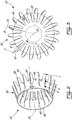
- the mixer 32 has a central longitudinal axis 33 and includes an annular wall 34 defining an upstream end 36 of the mixer 32 along which the flows from the main gas path 26 and from the bypass passage 24 are received, and a downstream end 38 where the two flows meet and are mixed together.
- the annular wall 34 includes a frustoconical portion 40 extending from and defining the upstream end 36, the frustoconical portion 40 having a diameter progressively reducing toward the downstream end 38.
- the annular wall 34 also defines a plurality of circumferentially distributed lobes extending rearwardly from the frustoconical portion 40.
- the lobes include alternating inner and outer lobes 42, 44, with the outer lobes 44 extending into the bypass passage 24 and the inner lobes 42 extending into the main gas path 26.
- the inner lobes 42 define troughs in the bypass passage 24 in between adjacent ones of the outer lobes 44, while the outer lobes 44 define troughs in the main gas path 26 in between adjacent ones of the inner lobes 42.
- each lobe 42, 44 has a radially elongated cross-section including a rounded tip 47, and extends from the frustoconical portion 40 to the downstream end 38 of the mixer 32.
- the present mixer 32 is configured to allow (e.g. maintain or increase) the swirl in the turbine exhaust flow for enhanced mixing.
- the mixer 32 allows for improved aerodynamic performance relative to a straight mixer design.
- each inner lobe 42 defines an imaginary valley line 43 extending substantially longitudinally through its radially innermost points.
- Each outer lobe 44 defines an imaginary crest line 45 extending longitudinally or substantially longitudinally through its radially outermost points.
- each crest line and each valley line extends longitudinally.
- the crest lines 45 and, optionally, the valley lines 43 are curved with respect to a circumferential direction of the mixer 32; in other words, the crest lines 45 and, optionally, the valley lines 43, have a curved shape when viewed in a respective direction which in a conventional straight mixer would superpose the crest line 45/valley line 43 with the longitudinal axis 33.
- the crest lines 45 are curved such as to define a circumferential offset with respect to the longitudinal axis 33 in the same direction as that of the swirl, as will be detailed further below.
- the path of the curved crest lines 45 and valley lines 43 are obtained from a straight mixer configuration through circumferentially twisting the crest lines 45 and valley lines 43 about the longitudinal axis 33.
- the circumferential twist of the crest lines 45 may be the same or different from that of the valley lines 43.
- the path of the curved crest lines 45 is obtained from a straight mixer configuration through pivoting of each crest line 45 about a respective pivot point located on a circle extending through the valley lines 43.
- any other type of curvature that deflects the crest lines 45 and optionally, the valley lines 43 in the circumferential direction may be used.
- the valley lines 43 may be deflected in the same or in an opposite direction as that of the crest lines 45.
- the crest lines 45 and, optionally, the valley lines 43 may be deflected at a constant rate along the longitudinal direction of the mixer 32, or alternately, the rate of deflection may vary along the longitudinal direction.
- the crest lines 45 and, optionally, the valley lines 43 can be deflected along only a downstream portion thereof, such that the outer lobes 44 and, optionally, the inner lobes 42 extend straight from the upstream end 36 up to location intermediate the upstream and downstream ends 36, 38 and then are circumferentially deflected between that location and the downstream end 38.
- the crest lines 45 and, optionally, the valley lines 43 are deflected along their entire length.
- FIG. 5 three (3) cross-sections of a same outer lobe 44 are shown, with each cross-section being located in a respective plane extending perpendicularly to the longitudinal axis 33, at the locations a, b, c shown in Fig. 2 .
- Cross section 44c is located in a plane at the downstream end 38 of the mixer 32
- cross-section 44a is located in a plane closer to the upstream end 36
- cross-section 44b is located in a plane between that of cross-sections 44a and 44c.
- Each outer lobe 44 includes a base 46 which is defined adjacent the frustoconical portion 40, at the upstream end of the crest line 45.
- the crest line 45 of each outer lobe 44 is circumferentially offset with respect to the base 46. It can be seen that an imaginary radial tip line Tc extending from the central longitudinal axis 33 to the crest line 45 is circumferentially offset from an imaginary radial base line B extending from the central longitudinal axis 33 to a midpoint of the base 46.
- the direction of the circumferential offset Oc from the base line B to the tip line Tc corresponds to the direction of the swirl S of the turbine exhaust flow entering the mixer 32.
- the offset angle Oc at the downstream end 38 is at most 5°. In a particular embodiment, the offset angle Oc at the downstream end 38 is at most 2°. In a particular embodiment, the offset angle Oc at the downstream end 38 end is at least 0.5°.
- the circumferential offset of the outer lobes 44 becomes progressively more pronounced toward the downstream end 38 of the mixer 32. Accordingly, the offset angle Oa from the radial base line B to the radial tip line Ta of the cross-section 44a closest to the upstream end 36 is smaller than the offset angle Ob from the radial base line B to the radial tip line Tb of the intermediary cross-section 44b, which is smaller than the offset angle Oc at the downstream end 38.
- each outer lobe 44 in cross-section defines an imaginary center line extending at equal distance from the wall portions defining the outer lobe 44, illustrated at C for the downstream end 38 in Fig. 2 .
- the center line C at the downstream end 38 is angled (i.e. extends at a non-zero angle) with respect to an imaginary radial line R extending from the longitudinal axis 33 and intersecting the center line C at the center of the tip 47; the outer lobe 44 is thus tilted with respect to the radial direction R.
- each outer lobe 44 has a straight center line C and is symmetrical with respect thereto.
- the center line C and wall portions forming the outer lobes 44 may be curved and/or the outer lobe 44 may be asymmetrical about the center line C.
- the trailing edge junction of each outer lobe 44 with the adjacent inner lobes 42 defines a scallop 48, from which extends a pointed tab 50.
- the trailing edge junction of each outer lobe 44 with the adjacent inner lobes 42 defines only a scallop 148. Any other adequate trailing edge treatment may alternately be used, for example a tabbed trailing edge.
- Fig. 7 shows an alternate embodiment for the mixer 132 where the crest lines 145 are curved relative to the longitudinal direction and where the valley lines 143 are straight.
- the valley lines 143 are coplanar with the longitudinal axis, such that the inner lobes 42 are straight and longitudinal.
- the path of the curved crest lines 145 is obtained through pivoting of each crest line 145 about a respective pivot point located on a circle extending through the valley lines 143.
- the turning of the outer lobe 44 through circumferential deflection of the crest line 45, 145 changes the trajectory of the crest vortex pair such that the centres of the vortices are at different radii.
- the mixing is achieved through radial vortices generated in the shear layer and pairs of counter rotating vortices generated by the core flow penetrating into the cold flow at the lobe crest and that are transported downstream symmetrically or substantially symmetrically (a small amount of residual swirl may prevent the flow from being exactly symmetrical).
- the centers 60, 60' of the pair of vortices are transported downstream symmetrically along a path 62 located at a same radial distance from the longitudinal axis 33.
- the offset of the outer lobes 44 changes the trajectory of the pairs of vortices such that the centers of adjacent vortices 160, 160' migrate to paths 162 defined at different radii. Because of the shift in radii, the span of radius over which the vortices have an effect is increased, increasing mixing. In addition, the two adjacent vortices of consecutive lobes are also at different radii which increase their interaction resulting in more cold flow between consecutive lobes being involved in the mixing process. Finally, the interactions of the vortices with the shear layer formed by the mixer side walls result in the shear layer deforming and increasing its surface area, further increasing the mixing area.
- offset outer lobes 44 result in an increase in the mixing downstream of the mixer 32, 132 without or with a limited increase in pressure loss. This may provide an increase in thrust coefficient over a straight mixer at the same engine condition, resulting in a reduction in specific fuel consumption.
- the minimum turn or offset angle to turn the flow sufficiently to cause the radial migration is 0.5°.
- the upper limit for the offset angle is determined such as to limit the pressure losses.
- the maximum offset angle is 2°. In another particular embodiment, the maximum offset angle is 5°. An offset angle that is too high may lead to an increase in lossed in the mixer and nozzle high enough to reduce the resulting thrust coefficient, which may cause an increase in specific fuel consumption instead of the desired reduction.
- Losses in the mixer and nozzle may include bypass loss (loss incurred from the outer lobe leading edge to the mixer trailing edge), core loss (loss incurred from the inner lobe leading edge to the mixer trailing edge) and/or mixing pressure loss (loss incurred from the mixer trailing edge to the nozzle exit).
- the improved mixing of the mixer 32, 132 is achieved by increasing the area of the shear layer between the core and bypass streams over which the two flows can mix, as compared with a straight mixer at the same engine condition.
- the improved mixing is achieved by adding a rotational component to the flow downstream of the mixer 32, 132 that causes additional interaction of the vortices generated by the mixer 32, 132.
- the mixer 32, 132 enhances the interaction of a low level of residual swirl in the core and bypass flow with the mixing flow structures, which results in residual swirl increasing performance. This is contrary to a straight mixer for which residual swirl is generally a performance penalty.
- the mixer 32, 132 allows for a higher allowable residual swirl with the benefit that the amount of deswirling required downstream of the low pressure turbine is reduced, lowering the loss of the turbine exhaust case. De-swirling TEC struts 19 (see Fig. 1 ) leaving some residual swirl may thus be used upstream of the mixer 32, 132.
- a limiting factor of mixer design may be avoidance of hot gas impingement on a nozzle wall 21 (see Fig. 1 ) downstream of the mixer, as nozzles are often made from composite material with temperature capabilities below the temperature of the hot gas.
- the degree of impingement is a function of the degree of penetration of the outer lobes into the cold flow.
- the area of mixing may be increased by increasing penetration, but the hot gas impingement on the nozzle wall limits the possible increase in penetration and as such the possible performance improvement.
- the offset outer lobes 44 of the mixer 32, 132 allow for an increased area of the shear layer of mixing when compared to a straight mixer having the same penetration, thus allowing a higher level of mixing to be achieved without impinging on the downstream nozzle.
- the mixer 32, 132 may be used in combination with a straight or canted nozzle, i.e. a nozzle having an exit centerline not in line with the longitudinal axis 33.
Landscapes
- Engineering & Computer Science (AREA)
- Mechanical Engineering (AREA)
- General Engineering & Computer Science (AREA)
- Chemical & Material Sciences (AREA)
- Combustion & Propulsion (AREA)
- Turbine Rotor Nozzle Sealing (AREA)
Claims (14)
- Gasturbinenmotor, der Folgendes umfasst:einen ringförmigen Bypass-Durchgang (24) zum Leiten von Luft von einer Ventilatorströmung;einen Hauptgaswegdurchgang (26) zum Aufnehmen einer Strömung, die eine Wirbelkomponente in eine gegebene Richtung aufweist; undeine Abgasmischvorrichtung (32), die dazu angepasst ist, die Strömung von dem Hauptgaswegdurchgang (26), die die Wirbelkomponente in die gegebene Richtung aufweist, aufzunehmen, wobei die Abgasmischvorrichtung (32) Folgendes umfasst:eine ringförmige Wand (34), die eine Mittellängsachse (33) definiert, wobei die ringförmige Wand (34) ein Stromaufwärts- und ein Stromabwärtsende (36, 38), die einander gegenüberliegen, aufweist und eine Vielzahl von umlaufend verteilten alternierenden inneren und äußeren Blüten (42, 44) definiert, wobei jede innere Blüte (42) in den Hauptgaswegdurchgang (26) hervorsteht und jede äußere Blüte (44) in den ringförmigen Bypass-Durchgang (24) hervorsteht,wobei jede äußere Blüte (44) eine Scheitellinie (45) aufweist, die sich im Wesentlichen in Längsrichtung durch jeden radial äußersten Punkt der äußeren Blüte (44) und eine Basis (46) erstreckt, die zwischen voneinander beabstandeten Wandabschnitten der äußeren Blüte (44) an einem Stromaufwärtsende der Scheitellinie (45) definiert ist, wobei mindestens ein Stromabwärtsabschnitt der Scheitellinie (45) hinsichtlich einer Umfangsrichtung der Abgasmischvorrichtung (32) gekrümmt ist, dadurch gekennzeichnet, dassdie Scheitellinie (45) jeder äußeren Blüte (44) derartig gekrümmt ist, um einen Versatz in Umlaufrichtung hinsichtlich der Längsachse (33) in dieselbe Richtung wie die der Wirbelkomponente der Strömung von dem Hauptgaswegdurchgang zu definieren, um den Wirbel in der Turbinenabgasströmung zu erhalten oder zu erhöhen.
- Gasturbinenmotor nach Anspruch 1, wobei jede äußere Blüte (44) in einem Querschnittsbereich, der an dem Stromabwärtsende positioniert ist, eine Mittellinie definiert, die sich in einem gleichen Abstand von den voneinander beabstandeten Wandabschnitten erstreckt, die die äußere Blüte (44) definieren, wobei die Mittellinie sich in einem Winkel ungleich null hinsichtlich einer radialen Linie, die sich von der Längsachse (33) erstreckt und die Mittelinie an der Spitze der äußeren Blüte (44) schneidet, erstreckt.
- Gasturbinenmotor nach Anspruch 2, wobei jede äußere Blüte (44) symmetrisch um die Mittellinie an dem Stromabwärtsende ist.
- Gasturbinenmotor nach einem der vorhergehenden Ansprüche, wobei der Versatz in Umfangsrichtung zwischen der Basis (46) und dem Stromabwärtsende höchstens 5 Grad beträgt.
- Gasturbinenmotor nach einem der vorhergehenden Ansprüche, wobei der Versatz in Umfangsrichtung an dem Stromabwärtsende höchstens 2 Grad beträgt.
- Gasturbinenmotor nach Anspruch 4 oder 5, wobei der Versatz in Umfangsrichtung an dem Stromabwärtsende mindestens 0,5 Grad beträgt.
- Gasturbinenmotor nach einem der vorhergehenden Ansprüche, wobei jede Scheitellinie (45) entlang einer gesamten Länge davon gekrümmt ist.
- Gasturbinenmotor nach einem der vorhergehenden Ansprüche, wobei jede innere Blüte (42) eine Tallinie (43) definiert, die sich im Wesentlichen in Längsrichtung durch jeden radial innersten Punkt der inneren Blüte (42) erstreckt, wobei mindestens ein Stromabwärtsabschnitt der Tallinie (43) hinsichtlich der Umfangsrichtung der Abgasmischvorrichtung (32) gekrümmt ist.
- Gasturbinenmotor nach Anspruch 8, wobei jede Scheitellinie (45) und jede Tallinie (43) entlang ihrer gesamten Länge gekrümmt sind.
- Gasturbinenmotor nach einem der Ansprüche 1 bis 7, wobei jede innere Blüte (42) eine Tallinie (43) definiert, die sich im Wesentlichen in Längsrichtung durch jeden radial innersten Punkt der inneren Blüte (42) erstreckt, wobei jede Tallinie (43) koplanar mit der Längsachse (43) ist.
- Gasturbinenmotor nach einem der vorhergehenden Ansprüche, wobei ein Weg jeder Scheitellinie (45) einer Verdrehung in Umfangsrichtung um die Mittellängsachse (33) entspricht.
- Gasturbinenmotor nach einem der vorhergehenden Ansprüche, wobei jede innere Blüte (42) eine Tallinie (43) definiert, die sich im Wesentlichen in Längsrichtung durch jeden radial innersten Punkt der inneren Blüte erstreckt, und wobei ein Weg jeder Scheitellinie (45) einer Schwenkung um einen entsprechenden Schwenkpunkt entspricht, der auf einem Durchmesser eines selben imaginären Kreises positioniert ist, der sich durch jede Tallinie (43) erstreckt.
- Verfahren zum Mischen der Kernströmung und der Bypass-Strömung, die die Kernströmung in dem Gasturbinenmotor nach einem der vorhergehenden Ansprüche umgibt, wobei das Verfahren Folgendes umfasst:Zirkulieren der Kernströmung durch die Abgasmischvorrichtung (32) und der Bypass-Strömung um dieAbgasmischvorrichtung (32);Erzeugen von Paaren von sich entgegengesetzt drehenden radialen Strudeln (160, 160') innerhalb der Kernströmung in der Nähe einer Spitze der äußeren Blüten (44); undmit den äußeren Blüten (44), Führen eines Stromabwärtstransports von Strudeln (160, 160'), sodass die benachbarten der Strudel in einem selben Paar sich entlang von verschiedenen Wegen, die in verschiedenen radialen Abständen von einer Längsachse der Abgasmischvorrichtung (32) definiert sind, bewegen.
- Verfahren nach Anspruch 13, ferner umfassend ein Führen des Stromabwärtstransports der Strudel mit den äußeren Blüten (44), sodass benachbarte der Strudel in benachbarten der äußeren Blüten sich entlang von Wegen, die in verschiedenen radialen Abständen von der Längsachse definiert sind, bewegen.
Applications Claiming Priority (1)
| Application Number | Priority Date | Filing Date | Title |
|---|---|---|---|
| US13/937,587 US11085333B2 (en) | 2013-07-09 | 2013-07-09 | Exhaust mixer with offset lobes |
Publications (2)
| Publication Number | Publication Date |
|---|---|
| EP2824308A1 EP2824308A1 (de) | 2015-01-14 |
| EP2824308B1 true EP2824308B1 (de) | 2018-12-26 |
Family
ID=51224676
Family Applications (1)
| Application Number | Title | Priority Date | Filing Date |
|---|---|---|---|
| EP14173655.3A Active EP2824308B1 (de) | 2013-07-09 | 2014-06-24 | Abgasmischvorrichtung mit versetzten Blüten |
Country Status (3)
| Country | Link |
|---|---|
| US (1) | US11085333B2 (de) |
| EP (1) | EP2824308B1 (de) |
| CA (1) | CA2851073C (de) |
Families Citing this family (13)
| Publication number | Priority date | Publication date | Assignee | Title |
|---|---|---|---|---|
| CA2940706C (en) * | 2015-09-29 | 2023-10-10 | Pratt & Whitney Canada Corp. | Gas turbine engine exhaust mixer with lobes cross-over offset |
| US10738649B2 (en) | 2017-08-03 | 2020-08-11 | Rolls-Royce Corporation | Reinforced oxide-oxide ceramic matrix composite (CMC) component and method of making a reinforced oxide-oxide CMC component |
| US12601283B2 (en) | 2019-04-08 | 2026-04-14 | Pratt & Whitney Canada Corp. | Turbine exhaust case mixer |
| CN113074061A (zh) * | 2021-04-01 | 2021-07-06 | 南昌航空大学 | 一种用于交变波瓣喷管的锯齿型波峰扰流片 |
| CN113047979A (zh) * | 2021-04-01 | 2021-06-29 | 南昌航空大学 | 一种用于带内斜切或扇形处理波瓣喷管的波瓣形波峰 |
| US20220325678A1 (en) * | 2021-04-08 | 2022-10-13 | Boom Technology, Inc. | Lobed mixer nozzles for supersonic and subsonic aircraft, and associated systems and methods |
| WO2022216468A1 (en) * | 2021-04-08 | 2022-10-13 | Boom Technology, Inc. | Lobed mixer nozzles for supersonic and subsonic aircraft, and associated systems and methods |
| CN113123898B (zh) * | 2021-04-19 | 2022-06-07 | 中国人民解放军国防科技大学 | 一种基于分隔板后缘射流扰动的超声速流混合装置 |
| US12162618B2 (en) | 2021-10-11 | 2024-12-10 | Boom Technology, Inc. | Dissimilarly shaped aircraft nozzles with tandem mixing devices, and associated systems and methods |
| CN114412656B (zh) * | 2022-01-25 | 2023-06-16 | 北京环境特性研究所 | 抑制排气系统后向红外辐射特征的混合器 |
| US11828248B1 (en) | 2022-06-27 | 2023-11-28 | Pratt & Whitney Canada Corp. | Rotatably driven exhaust mixer |
| US12442532B2 (en) * | 2023-01-10 | 2025-10-14 | Pratt & Whitney Canada Corp. | Exhaust mixer with protrusions |
| CN116378847B (zh) * | 2023-04-10 | 2023-09-29 | 南京航空航天大学 | 一种带传热和结构加强的单驱动波瓣喷管结构 |
Family Cites Families (9)
| Publication number | Priority date | Publication date | Assignee | Title |
|---|---|---|---|---|
| US4045957A (en) | 1976-02-20 | 1977-09-06 | United Technologies Corporation | Combined guide vane and mixer for a gas turbine engine |
| AU2404000A (en) * | 1999-01-04 | 2000-07-24 | Allison Advanced Development Company | Exhaust mixer and apparatus using same |
| US7506501B2 (en) | 2004-12-01 | 2009-03-24 | Honeywell International Inc. | Compact mixer with trimmable open centerbody |
| US7389635B2 (en) * | 2004-12-01 | 2008-06-24 | Honeywell International Inc. | Twisted mixer with open center body |
| FR2896274B1 (fr) | 2006-01-13 | 2008-04-18 | Snecma Sa | Melangeur de flux a section variable pour turboreacteur double flux d'avion supersonique |
| EP1870588B1 (de) * | 2006-06-19 | 2010-01-13 | Snecma | Mischer für ein Doppelstromtriebwerk und entsprechende Düse und Strahltriebwerk |
| FR2911922B1 (fr) | 2007-01-26 | 2009-04-24 | Snecma Sa | Melangeur de flux a section variable pour turboreacteur a double flux d'avion supersonique |
| US20100199626A1 (en) * | 2008-12-31 | 2010-08-12 | Benjamin Roland Harding | Turbine engine exhaust gas tube mixer |
| US8104260B2 (en) | 2009-05-22 | 2012-01-31 | Pratt & Whitney Canada Corp. | Deswirling exhaust mixer |
-
2013
- 2013-07-09 US US13/937,587 patent/US11085333B2/en active Active
-
2014
- 2014-05-02 CA CA2851073A patent/CA2851073C/en active Active
- 2014-06-24 EP EP14173655.3A patent/EP2824308B1/de active Active
Non-Patent Citations (1)
| Title |
|---|
| None * |
Also Published As
| Publication number | Publication date |
|---|---|
| US11085333B2 (en) | 2021-08-10 |
| US20150013341A1 (en) | 2015-01-15 |
| CA2851073C (en) | 2022-08-09 |
| CA2851073A1 (en) | 2015-01-09 |
| EP2824308A1 (de) | 2015-01-14 |
Similar Documents
| Publication | Publication Date | Title |
|---|---|---|
| EP2824308B1 (de) | Abgasmischvorrichtung mit versetzten Blüten | |
| EP2383455B1 (de) | Abgasmischdüse für Gasturbinentriebwerk | |
| US6314721B1 (en) | Tabbed nozzle for jet noise suppression | |
| EP2258925A2 (de) | Kühlanordnungen | |
| US20190106991A1 (en) | Engine component | |
| US20100293958A1 (en) | Deswirling exhaust mixer | |
| US20140260283A1 (en) | Gas turbine engine exhaust mixer with aerodynamic struts | |
| EP2660424A1 (de) | Turbinenverbindungskanäle mit variablen Flächenverhältnissen | |
| US10267161B2 (en) | Gas turbine engine with fillet film holes | |
| US20160326983A1 (en) | Integrated tec/mixer strut axial position | |
| EP3181880B1 (de) | Gasturbinenmotor-abgasmischer mit versetztem lappenansatz | |
| EP2587037A2 (de) | Mischeranordnung eines Turbolüftermotors | |
| US20190301488A1 (en) | Gas path duct for a gas turbine engine | |
| US20160032865A1 (en) | Gas turbine engine ejector | |
| CN115507382B (zh) | 用于燃烧器的具有凹口尖端和开槽尾部的稀释空气入口 | |
| US12442532B2 (en) | Exhaust mixer with protrusions | |
| US12163486B2 (en) | Exhaust mixer with protrusions | |
| EP4400707A1 (de) | Abgasmischer mit vorsprüngen | |
| EP4343115B1 (de) | Schaufel für ein triebwerk mit einem schlitz | |
| EP3150836A1 (de) | Axiale position einer integrierten tec-/mischerstrebe | |
| US20180216475A1 (en) | Component for a gas turbine engine | |
| WO2017023331A1 (en) | Ducting arrangement for directing combustion gas |
Legal Events
| Date | Code | Title | Description |
|---|---|---|---|
| 17P | Request for examination filed |
Effective date: 20140624 |
|
| AK | Designated contracting states |
Kind code of ref document: A1 Designated state(s): AL AT BE BG CH CY CZ DE DK EE ES FI FR GB GR HR HU IE IS IT LI LT LU LV MC MK MT NL NO PL PT RO RS SE SI SK SM TR |
|
| AX | Request for extension of the european patent |
Extension state: BA ME |
|
| PUAI | Public reference made under article 153(3) epc to a published international application that has entered the european phase |
Free format text: ORIGINAL CODE: 0009012 |
|
| R17P | Request for examination filed (corrected) |
Effective date: 20150714 |
|
| RBV | Designated contracting states (corrected) |
Designated state(s): AL AT BE BG CH CY CZ DE DK EE ES FI FR GB GR HR HU IE IS IT LI LT LU LV MC MK MT NL NO PL PT RO RS SE SI SK SM TR |
|
| 17Q | First examination report despatched |
Effective date: 20160302 |
|
| GRAP | Despatch of communication of intention to grant a patent |
Free format text: ORIGINAL CODE: EPIDOSNIGR1 |
|
| STAA | Information on the status of an ep patent application or granted ep patent |
Free format text: STATUS: GRANT OF PATENT IS INTENDED |
|
| INTG | Intention to grant announced |
Effective date: 20180628 |
|
| GRAS | Grant fee paid |
Free format text: ORIGINAL CODE: EPIDOSNIGR3 |
|
| GRAA | (expected) grant |
Free format text: ORIGINAL CODE: 0009210 |
|
| STAA | Information on the status of an ep patent application or granted ep patent |
Free format text: STATUS: THE PATENT HAS BEEN GRANTED |
|
| AK | Designated contracting states |
Kind code of ref document: B1 Designated state(s): AL AT BE BG CH CY CZ DE DK EE ES FI FR GB GR HR HU IE IS IT LI LT LU LV MC MK MT NL NO PL PT RO RS SE SI SK SM TR |
|
| REG | Reference to a national code |
Ref country code: GB Ref legal event code: FG4D |
|
| REG | Reference to a national code |
Ref country code: CH Ref legal event code: EP |
|
| REG | Reference to a national code |
Ref country code: AT Ref legal event code: REF Ref document number: 1081760 Country of ref document: AT Kind code of ref document: T Effective date: 20190115 |
|
| REG | Reference to a national code |
Ref country code: DE Ref legal event code: R096 Ref document number: 602014038498 Country of ref document: DE |
|
| REG | Reference to a national code |
Ref country code: IE Ref legal event code: FG4D |
|
| PG25 | Lapsed in a contracting state [announced via postgrant information from national office to epo] |
Ref country code: NO Free format text: LAPSE BECAUSE OF FAILURE TO SUBMIT A TRANSLATION OF THE DESCRIPTION OR TO PAY THE FEE WITHIN THE PRESCRIBED TIME-LIMIT Effective date: 20190326 Ref country code: HR Free format text: LAPSE BECAUSE OF FAILURE TO SUBMIT A TRANSLATION OF THE DESCRIPTION OR TO PAY THE FEE WITHIN THE PRESCRIBED TIME-LIMIT Effective date: 20181226 Ref country code: BG Free format text: LAPSE BECAUSE OF FAILURE TO SUBMIT A TRANSLATION OF THE DESCRIPTION OR TO PAY THE FEE WITHIN THE PRESCRIBED TIME-LIMIT Effective date: 20190326 Ref country code: LT Free format text: LAPSE BECAUSE OF FAILURE TO SUBMIT A TRANSLATION OF THE DESCRIPTION OR TO PAY THE FEE WITHIN THE PRESCRIBED TIME-LIMIT Effective date: 20181226 Ref country code: FI Free format text: LAPSE BECAUSE OF FAILURE TO SUBMIT A TRANSLATION OF THE DESCRIPTION OR TO PAY THE FEE WITHIN THE PRESCRIBED TIME-LIMIT Effective date: 20181226 Ref country code: LV Free format text: LAPSE BECAUSE OF FAILURE TO SUBMIT A TRANSLATION OF THE DESCRIPTION OR TO PAY THE FEE WITHIN THE PRESCRIBED TIME-LIMIT Effective date: 20181226 |
|
| REG | Reference to a national code |
Ref country code: NL Ref legal event code: MP Effective date: 20181226 |
|
| REG | Reference to a national code |
Ref country code: LT Ref legal event code: MG4D |
|
| PG25 | Lapsed in a contracting state [announced via postgrant information from national office to epo] |
Ref country code: AL Free format text: LAPSE BECAUSE OF FAILURE TO SUBMIT A TRANSLATION OF THE DESCRIPTION OR TO PAY THE FEE WITHIN THE PRESCRIBED TIME-LIMIT Effective date: 20181226 Ref country code: SE Free format text: LAPSE BECAUSE OF FAILURE TO SUBMIT A TRANSLATION OF THE DESCRIPTION OR TO PAY THE FEE WITHIN THE PRESCRIBED TIME-LIMIT Effective date: 20181226 Ref country code: RS Free format text: LAPSE BECAUSE OF FAILURE TO SUBMIT A TRANSLATION OF THE DESCRIPTION OR TO PAY THE FEE WITHIN THE PRESCRIBED TIME-LIMIT Effective date: 20181226 Ref country code: GR Free format text: LAPSE BECAUSE OF FAILURE TO SUBMIT A TRANSLATION OF THE DESCRIPTION OR TO PAY THE FEE WITHIN THE PRESCRIBED TIME-LIMIT Effective date: 20190327 |
|
| REG | Reference to a national code |
Ref country code: AT Ref legal event code: MK05 Ref document number: 1081760 Country of ref document: AT Kind code of ref document: T Effective date: 20181226 |
|
| PG25 | Lapsed in a contracting state [announced via postgrant information from national office to epo] |
Ref country code: NL Free format text: LAPSE BECAUSE OF FAILURE TO SUBMIT A TRANSLATION OF THE DESCRIPTION OR TO PAY THE FEE WITHIN THE PRESCRIBED TIME-LIMIT Effective date: 20181226 |
|
| PG25 | Lapsed in a contracting state [announced via postgrant information from national office to epo] |
Ref country code: PT Free format text: LAPSE BECAUSE OF FAILURE TO SUBMIT A TRANSLATION OF THE DESCRIPTION OR TO PAY THE FEE WITHIN THE PRESCRIBED TIME-LIMIT Effective date: 20190426 Ref country code: CZ Free format text: LAPSE BECAUSE OF FAILURE TO SUBMIT A TRANSLATION OF THE DESCRIPTION OR TO PAY THE FEE WITHIN THE PRESCRIBED TIME-LIMIT Effective date: 20181226 Ref country code: IT Free format text: LAPSE BECAUSE OF FAILURE TO SUBMIT A TRANSLATION OF THE DESCRIPTION OR TO PAY THE FEE WITHIN THE PRESCRIBED TIME-LIMIT Effective date: 20181226 Ref country code: PL Free format text: LAPSE BECAUSE OF FAILURE TO SUBMIT A TRANSLATION OF THE DESCRIPTION OR TO PAY THE FEE WITHIN THE PRESCRIBED TIME-LIMIT Effective date: 20181226 Ref country code: ES Free format text: LAPSE BECAUSE OF FAILURE TO SUBMIT A TRANSLATION OF THE DESCRIPTION OR TO PAY THE FEE WITHIN THE PRESCRIBED TIME-LIMIT Effective date: 20181226 |
|
| PGFP | Annual fee paid to national office [announced via postgrant information from national office to epo] |
Ref country code: DE Payment date: 20190521 Year of fee payment: 6 |
|
| PG25 | Lapsed in a contracting state [announced via postgrant information from national office to epo] |
Ref country code: SM Free format text: LAPSE BECAUSE OF FAILURE TO SUBMIT A TRANSLATION OF THE DESCRIPTION OR TO PAY THE FEE WITHIN THE PRESCRIBED TIME-LIMIT Effective date: 20181226 Ref country code: EE Free format text: LAPSE BECAUSE OF FAILURE TO SUBMIT A TRANSLATION OF THE DESCRIPTION OR TO PAY THE FEE WITHIN THE PRESCRIBED TIME-LIMIT Effective date: 20181226 Ref country code: RO Free format text: LAPSE BECAUSE OF FAILURE TO SUBMIT A TRANSLATION OF THE DESCRIPTION OR TO PAY THE FEE WITHIN THE PRESCRIBED TIME-LIMIT Effective date: 20181226 Ref country code: IS Free format text: LAPSE BECAUSE OF FAILURE TO SUBMIT A TRANSLATION OF THE DESCRIPTION OR TO PAY THE FEE WITHIN THE PRESCRIBED TIME-LIMIT Effective date: 20190426 Ref country code: SK Free format text: LAPSE BECAUSE OF FAILURE TO SUBMIT A TRANSLATION OF THE DESCRIPTION OR TO PAY THE FEE WITHIN THE PRESCRIBED TIME-LIMIT Effective date: 20181226 |
|
| REG | Reference to a national code |
Ref country code: DE Ref legal event code: R097 Ref document number: 602014038498 Country of ref document: DE |
|
| PG25 | Lapsed in a contracting state [announced via postgrant information from national office to epo] |
Ref country code: DK Free format text: LAPSE BECAUSE OF FAILURE TO SUBMIT A TRANSLATION OF THE DESCRIPTION OR TO PAY THE FEE WITHIN THE PRESCRIBED TIME-LIMIT Effective date: 20181226 Ref country code: AT Free format text: LAPSE BECAUSE OF FAILURE TO SUBMIT A TRANSLATION OF THE DESCRIPTION OR TO PAY THE FEE WITHIN THE PRESCRIBED TIME-LIMIT Effective date: 20181226 |
|
| PLBE | No opposition filed within time limit |
Free format text: ORIGINAL CODE: 0009261 |
|
| STAA | Information on the status of an ep patent application or granted ep patent |
Free format text: STATUS: NO OPPOSITION FILED WITHIN TIME LIMIT |
|
| 26N | No opposition filed |
Effective date: 20190927 |
|
| PG25 | Lapsed in a contracting state [announced via postgrant information from national office to epo] |
Ref country code: MC Free format text: LAPSE BECAUSE OF FAILURE TO SUBMIT A TRANSLATION OF THE DESCRIPTION OR TO PAY THE FEE WITHIN THE PRESCRIBED TIME-LIMIT Effective date: 20181226 |
|
| REG | Reference to a national code |
Ref country code: CH Ref legal event code: PL |
|
| PG25 | Lapsed in a contracting state [announced via postgrant information from national office to epo] |
Ref country code: SI Free format text: LAPSE BECAUSE OF FAILURE TO SUBMIT A TRANSLATION OF THE DESCRIPTION OR TO PAY THE FEE WITHIN THE PRESCRIBED TIME-LIMIT Effective date: 20181226 |
|
| REG | Reference to a national code |
Ref country code: BE Ref legal event code: MM Effective date: 20190630 |
|
| PG25 | Lapsed in a contracting state [announced via postgrant information from national office to epo] |
Ref country code: TR Free format text: LAPSE BECAUSE OF FAILURE TO SUBMIT A TRANSLATION OF THE DESCRIPTION OR TO PAY THE FEE WITHIN THE PRESCRIBED TIME-LIMIT Effective date: 20181226 |
|
| PG25 | Lapsed in a contracting state [announced via postgrant information from national office to epo] |
Ref country code: IE Free format text: LAPSE BECAUSE OF NON-PAYMENT OF DUE FEES Effective date: 20190624 |
|
| PG25 | Lapsed in a contracting state [announced via postgrant information from national office to epo] |
Ref country code: LU Free format text: LAPSE BECAUSE OF NON-PAYMENT OF DUE FEES Effective date: 20190624 Ref country code: LI Free format text: LAPSE BECAUSE OF NON-PAYMENT OF DUE FEES Effective date: 20190630 Ref country code: CH Free format text: LAPSE BECAUSE OF NON-PAYMENT OF DUE FEES Effective date: 20190630 Ref country code: BE Free format text: LAPSE BECAUSE OF NON-PAYMENT OF DUE FEES Effective date: 20190630 |
|
| REG | Reference to a national code |
Ref country code: DE Ref legal event code: R119 Ref document number: 602014038498 Country of ref document: DE |
|
| PG25 | Lapsed in a contracting state [announced via postgrant information from national office to epo] |
Ref country code: DE Free format text: LAPSE BECAUSE OF NON-PAYMENT OF DUE FEES Effective date: 20210101 Ref country code: CY Free format text: LAPSE BECAUSE OF FAILURE TO SUBMIT A TRANSLATION OF THE DESCRIPTION OR TO PAY THE FEE WITHIN THE PRESCRIBED TIME-LIMIT Effective date: 20181226 |
|
| PG25 | Lapsed in a contracting state [announced via postgrant information from national office to epo] |
Ref country code: HU Free format text: LAPSE BECAUSE OF FAILURE TO SUBMIT A TRANSLATION OF THE DESCRIPTION OR TO PAY THE FEE WITHIN THE PRESCRIBED TIME-LIMIT; INVALID AB INITIO Effective date: 20140624 Ref country code: MT Free format text: LAPSE BECAUSE OF FAILURE TO SUBMIT A TRANSLATION OF THE DESCRIPTION OR TO PAY THE FEE WITHIN THE PRESCRIBED TIME-LIMIT Effective date: 20181226 |
|
| PG25 | Lapsed in a contracting state [announced via postgrant information from national office to epo] |
Ref country code: MK Free format text: LAPSE BECAUSE OF FAILURE TO SUBMIT A TRANSLATION OF THE DESCRIPTION OR TO PAY THE FEE WITHIN THE PRESCRIBED TIME-LIMIT Effective date: 20181226 |
|
| P01 | Opt-out of the competence of the unified patent court (upc) registered |
Effective date: 20230530 |
|
| PGFP | Annual fee paid to national office [announced via postgrant information from national office to epo] |
Ref country code: GB Payment date: 20250520 Year of fee payment: 12 |
|
| PGFP | Annual fee paid to national office [announced via postgrant information from national office to epo] |
Ref country code: FR Payment date: 20250520 Year of fee payment: 12 |