EP2824662A1 - Traitement audio - Google Patents
Traitement audio Download PDFInfo
- Publication number
- EP2824662A1 EP2824662A1 EP14171647.2A EP14171647A EP2824662A1 EP 2824662 A1 EP2824662 A1 EP 2824662A1 EP 14171647 A EP14171647 A EP 14171647A EP 2824662 A1 EP2824662 A1 EP 2824662A1
- Authority
- EP
- European Patent Office
- Prior art keywords
- audio
- frequency sub
- signal
- signals
- band
- Prior art date
- Legal status (The legal status is an assumption and is not a legal conclusion. Google has not performed a legal analysis and makes no representation as to the accuracy of the status listed.)
- Withdrawn
Links
- 238000012545 processing Methods 0.000 title description 37
- 230000005236 sound signal Effects 0.000 claims abstract description 119
- 238000000034 method Methods 0.000 claims abstract description 66
- 238000013507 mapping Methods 0.000 claims description 7
- 238000000354 decomposition reaction Methods 0.000 claims description 3
- 238000001914 filtration Methods 0.000 claims description 3
- 230000001419 dependent effect Effects 0.000 claims description 2
- 230000002596 correlated effect Effects 0.000 claims 1
- 230000006870 function Effects 0.000 description 21
- 238000004590 computer program Methods 0.000 description 19
- 238000004458 analytical method Methods 0.000 description 15
- 238000007781 pre-processing Methods 0.000 description 6
- 238000005516 engineering process Methods 0.000 description 5
- 230000002123 temporal effect Effects 0.000 description 4
- 230000008901 benefit Effects 0.000 description 3
- 238000004891 communication Methods 0.000 description 3
- 238000011524 similarity measure Methods 0.000 description 3
- 241000238413 Octopus Species 0.000 description 2
- 238000010276 construction Methods 0.000 description 2
- 210000005069 ears Anatomy 0.000 description 2
- 238000009877 rendering Methods 0.000 description 2
- 238000005070 sampling Methods 0.000 description 2
- 238000012546 transfer Methods 0.000 description 2
- 238000013459 approach Methods 0.000 description 1
- 238000003491 array Methods 0.000 description 1
- 230000009286 beneficial effect Effects 0.000 description 1
- 238000006243 chemical reaction Methods 0.000 description 1
- 230000001066 destructive effect Effects 0.000 description 1
- 238000010586 diagram Methods 0.000 description 1
- 238000004519 manufacturing process Methods 0.000 description 1
- 239000013598 vector Substances 0.000 description 1
Images


Classifications
-
- G—PHYSICS
- G10—MUSICAL INSTRUMENTS; ACOUSTICS
- G10L—SPEECH ANALYSIS TECHNIQUES OR SPEECH SYNTHESIS; SPEECH RECOGNITION; SPEECH OR VOICE PROCESSING TECHNIQUES; SPEECH OR AUDIO CODING OR DECODING
- G10L19/00—Speech or audio signals analysis-synthesis techniques for redundancy reduction, e.g. in vocoders; Coding or decoding of speech or audio signals, using source filter models or psychoacoustic analysis
- G10L19/04—Speech or audio signals analysis-synthesis techniques for redundancy reduction, e.g. in vocoders; Coding or decoding of speech or audio signals, using source filter models or psychoacoustic analysis using predictive techniques
- G10L19/26—Pre-filtering or post-filtering
- G10L19/265—Pre-filtering, e.g. high frequency emphasis prior to encoding
-
- G—PHYSICS
- G10—MUSICAL INSTRUMENTS; ACOUSTICS
- G10L—SPEECH ANALYSIS TECHNIQUES OR SPEECH SYNTHESIS; SPEECH RECOGNITION; SPEECH OR VOICE PROCESSING TECHNIQUES; SPEECH OR AUDIO CODING OR DECODING
- G10L19/00—Speech or audio signals analysis-synthesis techniques for redundancy reduction, e.g. in vocoders; Coding or decoding of speech or audio signals, using source filter models or psychoacoustic analysis
- G10L19/008—Multichannel audio signal coding or decoding using interchannel correlation to reduce redundancy, e.g. joint-stereo, intensity-coding or matrixing
-
- G—PHYSICS
- G10—MUSICAL INSTRUMENTS; ACOUSTICS
- G10L—SPEECH ANALYSIS TECHNIQUES OR SPEECH SYNTHESIS; SPEECH RECOGNITION; SPEECH OR VOICE PROCESSING TECHNIQUES; SPEECH OR AUDIO CODING OR DECODING
- G10L19/00—Speech or audio signals analysis-synthesis techniques for redundancy reduction, e.g. in vocoders; Coding or decoding of speech or audio signals, using source filter models or psychoacoustic analysis
- G10L19/02—Speech or audio signals analysis-synthesis techniques for redundancy reduction, e.g. in vocoders; Coding or decoding of speech or audio signals, using source filter models or psychoacoustic analysis using spectral analysis, e.g. transform vocoders or subband vocoders
- G10L19/0204—Speech or audio signals analysis-synthesis techniques for redundancy reduction, e.g. in vocoders; Coding or decoding of speech or audio signals, using source filter models or psychoacoustic analysis using spectral analysis, e.g. transform vocoders or subband vocoders using subband decomposition
-
- G—PHYSICS
- G10—MUSICAL INSTRUMENTS; ACOUSTICS
- G10L—SPEECH ANALYSIS TECHNIQUES OR SPEECH SYNTHESIS; SPEECH RECOGNITION; SPEECH OR VOICE PROCESSING TECHNIQUES; SPEECH OR AUDIO CODING OR DECODING
- G10L21/00—Speech or voice signal processing techniques to produce another audible or non-audible signal, e.g. visual or tactile, in order to modify its quality or its intelligibility
- G10L21/02—Speech enhancement, e.g. noise reduction or echo cancellation
- G10L21/0272—Voice signal separating
- G10L21/028—Voice signal separating using properties of sound source
-
- H—ELECTRICITY
- H04—ELECTRIC COMMUNICATION TECHNIQUE
- H04S—STEREOPHONIC SYSTEMS
- H04S7/00—Indicating arrangements; Control arrangements, e.g. balance control
- H04S7/30—Control circuits for electronic adaptation of the sound field
- H04S7/302—Electronic adaptation of stereophonic sound system to listener position or orientation
-
- G—PHYSICS
- G10—MUSICAL INSTRUMENTS; ACOUSTICS
- G10L—SPEECH ANALYSIS TECHNIQUES OR SPEECH SYNTHESIS; SPEECH RECOGNITION; SPEECH OR VOICE PROCESSING TECHNIQUES; SPEECH OR AUDIO CODING OR DECODING
- G10L21/00—Speech or voice signal processing techniques to produce another audible or non-audible signal, e.g. visual or tactile, in order to modify its quality or its intelligibility
- G10L21/02—Speech enhancement, e.g. noise reduction or echo cancellation
- G10L21/0208—Noise filtering
- G10L21/0216—Noise filtering characterised by the method used for estimating noise
- G10L2021/02161—Number of inputs available containing the signal or the noise to be suppressed
- G10L2021/02166—Microphone arrays; Beamforming
Definitions
- the example and non-limiting embodiments of the present invention relate to processing of audio signals.
- at least some example embodiments relate to a method, to an apparatus and/or to a computer program for providing one or more audio objects on basis of a source audio signal.
- Object oriented audio formats have recently emerged. Examples of such formats may include DOLBY ATMOS by DOLBY LABORATORIES INC., Moving Pictures Expert Group Spatial Audio Object Coding (MPEC SAOC) and AURO 3D by AURO TECHNOLOGIES.
- MPEC SAOC Moving Pictures Expert Group Spatial Audio Object Coding
- AURO 3D AURO TECHNOLOGIES.
- Object oriented audio formats provide some benefits over conventional audio downmixes that assume a fixed predetermined channel and/or loudspeaker configuration. For an end-user probably an important benefit may be the ability to play back the audio using any equipment and any loudspeaker configuration whilst still achieving a high audio quality, which may not be the case when using traditional audio downmixes relying on a predetermined channel/loudspeaker configuration, such as ones according to the 5.1 channel surround/spatial audio.
- object oriented audio formats may be played using equipment such as use headphones, 5.1 surround audio in a home theater, mono/stereo speakers in a television set or speakers of a mobile device such as a mobile phone or a portable music player and the like.
- An audio object according to an object oriented audio format is typically created by recording the sound corresponding to the audio object separately from any other sound sources to avoid incorporating ambient components to the actual directional sound representing the audio object.
- recordings are mostly carried out in anechoic conditions, e.g. in studio conditions, employing well-known microphone setup.
- Such recording conditions and/or equipment are typically not available for end-users. Therefore, it would be advantageous to provide an audio processing technique that enables creating audio objects according to an object oriented audio format on basis of a pre-recorded audio signals and/or on basis of audio signal recorded using equipment and conditions that are readily available for the general public.
- an apparatus comprising at least one processor and at least one memory including computer program code for one or more programs, the at least one memory and the computer program code configured to, with the at least one processor, cause the apparatus at least to obtain a plurality of frequency sub-band signals, each representing a directional component of a source audio signal in the respective frequency sub-band, to obtain an indication of dominant sound source direction for one or more of said frequency sub-band signals, and to create one or more audio objects on basis of said plurality of frequency sub-band signals and said indications, said creating comprising deriving one or more audio object signals, each audio object signal comprising a respective directional signal determined on basis of frequency sub-band signals for which dominant sound source direction falls within a respective predetermined range of source directions and deriving one or more audio object direction indications for said one or more audio object signals, each audio object direction indication derived on basis of dominant sound source directions for the frequency sub-band signals used for determining the respective directional signal.
- another apparatus comprising means for obtaining a plurality of frequency sub-band signals, each representing a directional component of a source audio signal in the respective frequency sub-band, means for obtaining an indication of dominant sound source direction for one or more of said frequency sub-band signals, and means for creating one or more audio objects on basis of said plurality of frequency sub-band signals and said indications, the means for creating arranged to derive one or more audio object signals, each audio object signal comprising a respective directional signal determined on basis of frequency sub-band signals for which dominant sound source direction falls within a respective predetermined range of source directions and to derive one or more audio object direction indications for said one or more audio object signals, each audio object direction indication derived on basis of dominant sound source directions for the frequency sub-band signals used for determining the respective directional signal.
- a method comprising obtaining a plurality of frequency sub-band signals, each representing a directional component of a source audio signal in the respective frequency sub-band, obtaining an indication of dominant sound source direction for one or more of said frequency sub-band signals, and creating one or more audio objects on basis of said plurality of frequency sub-band signals and said indications, said creating comprising deriving one or more audio object signals, each audio object signal comprising a respective directional signal determined on basis of frequency sub-band signals for which dominant sound source direction falls within a respective predetermined range of source directions and deriving one or more audio object direction indications for said one or more audio object signals, each audio object direction indication derived on basis of dominant sound source directions for the frequency sub-band signals used for determining the respective directional signal.
- a computer program including one or more sequences of one or more instructions which, when executed by one or more processors, cause an apparatus at least to obtain a plurality of frequency sub-band signals, each representing a directional component of a source audio signal in the respective frequency sub-band, to obtain an indication of dominant sound source direction for one or more of said frequency sub-band signals, and to create one or more audio objects on basis of said plurality of frequency sub-band signals and said indications, said creating comprising deriving one or more audio object signals, each audio object signal comprising a respective directional signal determined on basis of frequency sub-band signals for which dominant sound source direction falls within a respective predetermined range of source directions and deriving one or more audio object direction indications for said one or more audio object signals, each audio object direction indication derived on basis of dominant sound source directions for the frequency sub-band signals used for determining the respective directional signal.
- the computer program referred to above may be embodied on a volatile or a nonvolatile computer-readable record medium, for example as a computer program product comprising at least one computer readable non-transitory medium having program code stored thereon, the program which when executed by an apparatus cause the apparatus at least to perform the operations described hereinbefore for the computer program according to the fifth aspect of the invention.
- Figure 1 schematically illustrates the concept of spatial or directional hearing.
- a listener 120 depicted directly from above, receives a sound originating from a sound source 110 that is in a left side in front of the listener 120 and another sound from a sound source 110' that is in a right side in front of the listener 120.
- the distance from the sound source 110 to the left ear of the listener 120 is shorter than the distance from the sound source 110 to the right ear of the listener 120, consequently resulting in the sound originating from the sound source 110 being received at the left ear of the listener 120 slightly before the corresponding sound is received at the right ear of the listener 120.
- a microphone array arranged at the position of the listener 120, e.g. at the position where the coordinate lines 140 ("x axis") and 150 ("y-axis") intersect: a first microphone of the array that is more to the left in direction of the line 140 than a second microphone of the array receives the sound from the sound source 110 earlier and at a higher signal level than the second microphone, while the first microphone receives the sound from the sound source 110' later and at a lower signal level than the second microphone. Consequently, the audio signals captured by the first and second microphones exhibit the time and level differences described hereinbefore by using the sound sources 110 and 110' as examples.
- such a microphone array may consist of two microphones (e.g. to model hearing by the left and right ears), or such a microphone array may comprise more than two microphones in a desired geographical configuration.
- any pair of audio signals captured by the microphones of the array exhibit the time and level differences that depend on the relative distances of the respective microphones from the corresponding sound source 110, 110'.
- the position of the listener and/or the position of the microphone array with respect to the sound source 110, 110' positions may be referred to as the (assumed) listening point.
- the time and/or level differences between a pair of audio signals representing the same sound source may be characterized e.g. by an inter-aural level difference (ILD) and/or an inter-aural time difference (ITD) between audio signals.
- ILD inter-aural level difference
- ITD inter-aural time difference
- the ILD and/or ITD may characterize level and time differences e.g. between two channels of a stereophonic audio signal or between a pair of channels of a multi-channel audio signal, such as a 5.1 channel surround audio signal.
- the signal perceived at the right ear of the listener may be represented as a time-shifted and/or scaled version of the signal perceived at the left ear of the listener - and/or vice versa - where the extent of time-shift/scaling is characterized using the parameters ITD and/or ILD.
- Methods for deriving the parameters ITD and/or ILD on basis of a pair of audio signals are known in the art.
- the parameters ITD and/or ILD serve as indication(s) regarding the directional component represented by the pair of audio signals
- it may be more convenient to express the direction of arrival as angle with respect to a reference direction for example as an angle between the direction of arrival and a center axis represented by the line 150 in Figure 1 , e.g. as an angle 130 for the sound source 110 and/or as an angle 130' for the sound source 110'.
- various techniques may be applied to determine the angles 130,130', one approach involves using a mapping between the values of the ITD and/or ILD and the respective angle 130, 130'. Such a mapping between the value of ITD and/or ILD and the respective angle 130, 130' may be determined e.g.
- the ITD, ILD and/or the angle between the direction of arrival and the center axis may be considered as parameters representative the sound source direction with respect to the assumed listening point in a horizontal plane (defined by the lines/axes 140 and 150).
- the ITD, ILD and the angles 130, 130' serve as non-limiting examples of parameters indicative of the sound source direction in an audio image.
- the ITD, ILD and/or the angles 130, 130' may be frequency dependent, thereby suggesting possibly different values of the ITD, ILD and/or the angles 130, 130' (or other parameters indicative of a sound source direction) at different frequency sub-bands of the audio signal.
- the values of the ITD, ILD and/or the angles 130, 130' may vary over time. Therefore, the ITD, ILD and/or the angles 130, 130' may be determined or indicated separately for a number of temporal segments of the pair of audio signals - typically referred to as frames or time frames.
- an ILD, ITD and/or the angle 130, 130' may be determined for a number of frequency sub-bands to indicate the respective direction of arrival of a sound.
- an ILD, ITD and/or the angle 130, 130' may be determined for only some of the frequency sub-bands.
- ITD parameter may be considered as a dominant contributor to the perceived direction of arrival of a sound source at low frequencies, hence suggesting that an ITD may be determined only for a predetermined range of the lower frequencies (e.g. up to 2 kHz).
- FIG. 2 schematically illustrates an audio processing arrangement 200 for converting an audio signal into one or more audio objects according to an embodiment.
- the arrangement 200 comprises a microphone array 210 for capturing a set of source audio signals 215.
- the set of source audio signals 215 may also be considered as the channels of a single source audio signal 215.
- the arrangement 200 further comprises an audio pre-processor 220 for determining, on basis of the set of source audio signals 215, a primary audio signal 225 representing a directional component in the source audio signals 215 and for determining indications of dominant sound source direction(s) 226 in an audio image represented by the source signals 215.
- the audio pre-processor 220 may be further arranged to determine one or more supplementary audio signals 227 representing the ambient component of the source audio signals 215.
- the arrangement 200 further comprises an audio mixer 250 for deriving one or more audio objects 255 on basis of the primary audio signal 225 and the indications of the dominant sound source directions.
- the arrangement 200 further comprises an audio encoding entity 280 for spatial audio encoding on basis of the one or more audio objects 255 and possibly further on basis of the supplementary audio signal(s) 227 to provide respective encoded audio objects 285.
- the arrangement 200 described hereinbefore exemplifies the processing chain from the audio capture by the microphone array 210 until provision of the audio objects 255 and possibly the supplementary audio signals 227 to the audio encoding entity 280 for encoding and subsequent audio decoding and/or audio rendering.
- the arrangement 200 enables on-line conversion of the source audio signals 215 into one or more encoded audio objects 285.
- the arrangement 200 may be, however, varied in a number of ways to support different usage scenarios.
- the microphone array 210 may be arranged to store the source audio signals 215 in a memory for subsequent access and processing by the audio pre-processor 220 and the further components in the processing chain according to the arrangement 200.
- the audio pre-processor 220 may be arranged to store the primary audio signal 225 and the direction indications 226 in a memory for subsequent access and processing by the audio mixer 250 and the further components in the processing chain according to the arrangement 200.
- the audio pre-processor 220 may be arranged to store the supplementary audio signal(s) 227 in a memory for further access and processing by the audio encoding entity 280.
- the audio mixer 250 may be arranged to store the audio objects 255 into a memory for subsequent access and processing by the audio encoding entity 280.
- Such variations of the arrangement 200' may enable scenarios where the source audio signals 215 are captured, possibly processed to some extent, and stored into a memory for subsequent further processing - thereby enabling off-line generation of the encoded audio objects 285.
- the arrangement 200 may be provided in an electronic device.
- the electronic device may be e.g. a mobile phone, a (portable) media player device, a (portable) music player device, a laptop computer, a desktop computer, a tablet computer, a personal digital assistant (PDA), a camera or video camera device, etc.
- the electronic device hosting the arrangement 200 further comprises control means for controlling the operation of the arrangement 200.
- the arrangement 200 may be provided by software means, by hardware means or by combination of software and hardware means.
- the control means may be provided e.g. as software portion arranged to control the operation of the arrangement 200 or as dedicated hardware portion arranged to control the operation of the arrangement 200.
- Figure 3 schematically illustrates the audio mixer 250 for converting an audio input signal into one or more audio objects according to an example embodiment.
- the audio mixer 250 preferably, obtains and processes the input audio signal 225 and the indications of dominant sound source directions 226 in time frames of suitable duration.
- the processing may be carried out for frames having temporal duration in the range from 5 to 100 ms (milliseconds), e.g. 20 ms.
- explicit references to individual time frames are omitted both from the textual description and from the equations for clarity and brevity of description.
- the audio mixer 250 is configured to obtain the primary audio signal 225 as an input audio signal M.
- the input audio signal M preferably, represents a directional audio component of the source audio signal 215.
- the input audio signal M may be obtained as pre-arranged into a plurality of frequency sub-band signals M b , each representing the directional audio component of the source audio signal 215 in the respective frequency sub-band b.
- the input audio signal M may be obtained as full-band signal, in other words as single signal portion covering all the frequency sub-bands of interest, and hence the audio mixer 250 may be configured to split the input audio signal M into frequency sub-band signals M b .
- the frequency range of interest may be divided into B frequency sub-bands.
- any division to frequency sub-bands may be employed, for example a sub-band division according the Equivalent Rectangular Bandwidth (ERB) scale, as known in the art, or a sub-band division approximating the ERB scale.
- ERB Equivalent Rectangular Bandwidth
- the audio mixer 250 is further configured to obtain an indication of dominant sound source direction(s) 226 in the audio image represented by the source audio signal 215 as a set of angles ⁇ b for one or more of said frequency sub-band signals M b .
- each angle ⁇ b indicates the dominant sound source direction for the respective frequency sub-band signal M b .
- An angle ⁇ b serves as an indication of the sound source direction with respect to a reference direction.
- the reference direction may be defined as the direction directly in front of the assumed listening point, e.g. as the center axis represented by the line 150 in the example of Figure 1 .
- angle 0° may represent the reference direction
- positive values of the angle between 0° to 180° may represent directions that are on the right side of the center axis
- negative values of the angle between 0° to -180° may represent direction that are on the left side of the center axis, with angle 180° (and/or -180°) representing the direction directly behind the assumed listening point.
- the indication of the dominant sound source directions 226 may be provided for each of the frequency sub-band signals M b , in other words for each of the B frequency sub-bands.
- the dominant sound source directions 226 may be provided for only predetermined portion of the frequency range, e.g. for a predetermined number of frequency sub-bands B ⁇ such that B ⁇ ⁇ B. Such an arrangement may be useful avoid handling of direction indications that are likely not beneficial for determination of the audio objects 255 and/or that indicate sound source directions for frequency sub-bands that are excluded from consideration in determination of the audio objects 255.
- one or more indications of dominant sound source directions 226, e.g.one or more of the angles ⁇ b , may be replaced by a predetermined indicator value that serves to indicate that there is no meaningful sound source direction available for the respective frequency sub-band signal.
- a predetermined indicator value that serves to indicate that there is no meaningful sound source direction available for the respective frequency sub-band signal.
- Such an indicator is referred herein as "null”
- the value ⁇ b null hence indicating a directionless frequency sub-band signal
- the frequency sub-bands for which a meaningful dominant sound source direction has been provided may be referred to as directional frequency sub-band signals.
- the sounds originating therefrom exhibit different frequency characteristics. Consequently, in some frequency sub-bands the dominant audio signal content originates from a first sound source (e.g. the sound source 110 of Figure 1 ) and hence the dominant sound source direction in the respective frequency sub-bands characterizes the direction/position of the first sound source with respect to the assumed listening point. On the other hand, in some other frequency sub-bands the dominant audio signal content originates from a second source (e.g. the sound source 110' of Figure 1 ), the dominant sound source direction in the respective frequency sub-bands thereby characterizing the direction/position of the second sound source with respect to the assumed listening point.
- a first sound source e.g. the sound source 110 of Figure 1
- the dominant sound source direction in the respective frequency sub-bands thereby characterizing the direction/position of the second sound source with respect to the assumed listening point.
- the audio mixer 250 is configured to create one or more audio objects 255 at least on basis of the frequency sub-band signals M b and on basis of the angles ⁇ b .
- an audio object 255 comprises an audio object signal C k and a respective audio object direction indication t k .
- an audio object direction indication t k serves to indicate the sound direction (to be) assigned for the audio object signal C k .
- the audio mixer 250 is configured to create at most a predetermined number Kof audio objects.
- a circle centered in assumed listening point in the horizontal plane (defined e.g. by the lines 140 and 150 in the example of Figure 1 ), i.e. a horizontal circle, is divided into K non-overlapping sectors, each sector hence covering a predetermined range of source directions.
- the ranges r k cover the horizontal circle in full, the ranges may be defined such that some portions of the horizontal circle, i.e. one or more ranges of the angles between -180° and 180° are not covered.
- the horizontal circle may be divided into three ranges r k ' in the following way.
- the audio mixer 250 is configured to assign each directional frequency sub-band signal, i.e. each frequency sub-band signal M b having a meaningful dominant sound source direction assigned thereto, e.g. into one of the K ranges r k in accordance with the angle ⁇ b provided therefor.
- the audio mixer 250 is further configured to derive directional signals C d,k on basis of frequency sub-band signals M b for which dominant sound source direction falls within a respective predetermined range r k of source directions.
- the number of frequency sub-band signals M b assigned to the range r k may be denoted as nk.
- the directional signals C d,k may be derived as a combination of the frequency sub-band signals M b assigned to the respective range, e.g. as a sum of the respective frequency sub-band signals according to equation (1)
- C d , k ⁇ ⁇ b ⁇ r k M b
- the non-directional signal C n may be derived e.g. as a sum, as an average or as a weighted average of the of the respective frequency sub-band signals M b . Moreover, the sum, the average or the weighted average may be scaled by a suitable scaling factor in order to provide the non-directional signal C n at a suitable signal level. If, as an example, considering only those frequency sub-band signals M b which are explicitly indicated not to carry meaningful direction information (i.e.
- the divisor K in the equation (2) may be replaced e.g. by a parameter indicating the number of audio objects 255 actually provided from the audio mixer 250.
- the divisor K in the equation (2) may be replaced e.g. by nn denoting the number of frequency sub-band signals M b that are indicated not to carry meaningful direction information in order to determine the non-directional signal C n as an average of the frequency sub-bands for which no directional information is provided.
- the output of the audio mixer 250 comprises K audio object signals, in which each of the K audio objects signals corresponds to a one of the ranges r k .
- the audio mixer 250 may be configured to omit the respective audio objects 255 from its output and thereby create and provide only the audio objects 255 corresponding to those ranges r k for which n k > 0.
- the audio mixer 250 is further configured to derive audio object direction indications t k for the respective audio object signals C k .
- the direction indications t k are derived on basis of the dominant sound source directions for the frequency sub-band signals M b used for determining the respective directional signals C d,k .
- the audio mixer 250 is preferably arranged to obtain the audio input signal M and/or the plurality of frequency sub-band signals M b as frequency domain signals, e.g. as Discrete Fourier Transform (DFT) coefficients covering the frequency range of interest, and hence to carry out any combination of frequency sub-band signals in the frequency-domain and, consequently, provide the audio object signals C k of the resulting audio objects 255 as frequency-domain signals.
- DFT Discrete Fourier Transform
- the audio mixer 250 may be configured to transform the audio object signals C k into time domain e.g. by applying inverse DFT.
- the audio mixer 250 may be arranged to obtain the input audio signals as time domain signals, transform the obtained time domain input audio signals into frequency domain signals e.g. by applying DFT before processing the frequency sub-band signals M b . Consequently, the resulting audio object signals C k may be provided as frequency domains signals or time domain signals.
- the audio mixer 250 be arranged to receive, carry out the processing and provide audio object signals C k as time-domain signals.
- the input audio signal M preferably represents the directional component of the source audio signals 215.
- the input audio signal M preferably represents the directional component without the ambient component of the source audio signals 215.
- Such an arrangement may be provided e.g. by applying a mid/side decomposition (e.g. in the audio pre-processor 220) to the source audio signals 215, resulting in a mid-signal representing the directional component of the source audio signals 215 and a side-signal representing the ambient component of the source audio signals 215.
- the mid-signal may serve as the input audio signal M representing (or estimating) the directional component of the source signals 215.
- the ambient component of the source audio signal 215 may be included in the supplementary audio signal(s) 227.
- the mid/side decomposition serves merely as a practical example of extracting a signal representing the directional component of the source audio signal 215 and any technique for extracting the directional signal component known in the art may be employed instead or in addition.
- the input audio signal M is preferably a single-channel signal, e.g. a monophonic audio signal.
- the audio mixer 250 may be configured to process a two-channel signal or a multi-channel signal of more than two channels. In such a scenario, the processing described in context of the equations (1) to (3) is repeated for each of the channels. Consequently, the audio mixer 250 may be e.g. configured to provide the audio object signals C k as two-channel signals or multi-channel signals or configured to downmix the two-channel or multi-channel audio object signals C k into respective single-channel audio object signals C k before provision as the output of the audio mixer 250.
- the term downmix signal is used to refer to a signal created as a combination of two or more signals or channels, e.g. as a sum or as an average of the signals or channels.
- FIG. 4 illustrates a method 400 in accordance with an example embodiment.
- the method 400 comprises obtaining an input audio signal 225, e.g. a plurality of frequency sub-band signals M b , each representing a directional component of a source audio signal 215 in the respective frequency sub-band b, as indicated in block 410.
- the method 400 further comprises obtaining indications of dominant sound source direction(s) 226 in an audio image represented by the source signals 215, e.g. as angles ⁇ b , for one or more of said frequency sub-band signals M b .
- the method 400 further comprises creating one or more audio objects 255 on basis of said plurality of frequency sub-band signals M b and said indications of dominant sound source direction(s) 226.
- the creation comprises deriving one or more audio object signals C k , each audio object signal C k derived at least on basis of frequency sub-band signals M b for which dominant sound source direction falls within a respective predetermined range of source directions, as indicated in block 430. This may involve determining a directional signal C d,k on basis of frequency sub-band signals M b for which dominant sound source direction falls within the respective predetermined range of source directions and deriving the respective audio object signal C k at least on bases of the directional signal C d,k .
- the creation further comprises deriving one or more audio object direction indications t k for said one or more audio object signals C k , each direction indication t k derived at least on basis of dominant sound source directions 226, e.g. the angles ⁇ b , for the frequency sub-band signals M b used for determining the respective audio object signal C k , as indicated in block 440. This may involve determining the audio object direction indications t k on basis of dominant sound source directions 226 indicated for the frequency sub-band signals M b used for determining the respective directional signal C d,k .
- the source audio signals 215 may, alternatively, be considered and/or referred to as channels of a single source audio signal 215.
- FIG. 5 schematically illustrates an arrangement 500 comprising a microphone array 510 and an audio pre-processor 520.
- the microphone array 510 may operate as the microphone array 210 of the arrangement 200 and the audio pre-processor 520 may operate as the audio pre-processor 220 of the arrangement 200.
- the microphone array 510 comprises three microphones 510-1, 510-2, and 510-3 arranged on a plane (e.g., horizontal level) in the geometrical shape of a triangle with vertices separated by distance, d, as schematically illustrated in Figure 6 .
- this technique described herein generalizes into different microphone setups and geometry.
- all the microphones are able to capture sound events from all directions, i.e., the microphones 510-1, 510-2, 510-3 are omnidirectional microphones.
- Each microphone produces typically an analog signal, which is transformed into a corresponding digital (sampled) audio signal 515-1, 515-2, 515-3 before provision to the audio pre-processor 520.
- the audio pre-processor 520 is configured to transform the source audio channels to the frequency domain using the DFT (block 710 in Figure 7 ).
- sinusoidal analysis window of N s samples with 50 percent overlap between successive analysis frames and effective length of 20 ms may be used for the DFT.
- D tot D max + D PROC zeroes are appended at the end of the analysis window.
- D max corresponds to the maximum delay (in samples) between the source audio channels, which is characteristics of the applied microphone setup.
- D max dF s v
- F s represents the sampling rate (i.e. the sampling frequency) of the source audio channels and wherein v represents the speed of the sound in the air.
- D PROC represents the maximum delay caused to the signal by processing applied to the source audio channel, such as filtering of the audio channel or (other) head related transfer function (HRTF) processing. In case no processing is (to be) applied or there is no delay associated with the processing, D PROC may be set to a zero value.
- HRTF head related transfer function
- N is the total length of the analysis window considering the sinusoidal window (length N s ) and the additional D tot zeroes appended at the end of the analysis window.
- the audio pre-processor 520 is configured to divide the frequency domain representations X k ( n ) of the source audio channels into B frequency sub-bands (block 720 in Figure 7 )
- X i b n X i ⁇ n b + n
- n 0 , ... , n b + 1 - n b - 1
- b 0 , ... , B - 1
- n b denotes the first index of b th frequency sub-band.
- the widths of the frequency sub-bands can follow, for example, the ERB scale known in the art, as also referred to hereinbefore in context of the audio mixer 250.
- the audio pre-processor 520 is configured to perform a directional analysis.
- the directional analysis may be performed as described in the following.
- a frequency sub-band is selected (block 730 in Figure 7 ), and directional analysis is performed on the respective frequency sub-band signals (block 740 in Figure 7 ).
- Such a directional analysis may determine a dominant sound source direction 226 in form of the angle ⁇ b , as described in context of the audio mixer 250.
- An example of a method for carrying out the directional analysis is provided in Figure 8 .
- it is determined if all frequency sub-bands have been processed (block 750 in Figure 7 ). If not, the processing continues with selection of the next frequency sub-band (block 730). If so, the directional analysis is complete (block 760 in Figure 7 ).
- the directional analysis for a single frequency sub-band may be performed according to a method 800 illustrated in Figure 8a , as described in the following.
- the method 800 may be applied as, for example, the directional analysis referred to in block 740 of the method 700.
- First the direction is estimated on basis of two source audio channels, described herein for the source audio channels 2 and 3.
- the time difference between the frequency-domain signals in those channels is determined and compensated for.
- the time difference compensation comprises finding delay ⁇ b that maximizes the correlation between two source audio channels for frequency sub-band b (block 810 in Figure 8a ) and time-shifting the signal in one or both source audio channels under analysis to time-align the channels (block 820 in Figure 8a ).
- X 2 , ⁇ b b and X 3 b are considered vectors with length of n b +1 - n b - 1 samples. Resolution of one sample is generally suitable for the search of the delay.
- a similarity measure different from correlation e.g. a perceptually motivated similarity measure
- the delay information a sum signal is created (block 830 in Figure 8a ).
- the content (i.e., frequency-domain signal) of the source audio channel in which an event occurs first is, preferably, provided as such, whereas the content (i.e., frequency-domain signal) of the source audio channel in which the event occurs later in time is shifted in time to obtain temporal alignment with the non-shifted source audio channel, i.e. to time-align the two channels.
- time-align the audio channels e.g. by time-shifting the both audio channels such that the sum of the time-shifting equals to the determined time difference ⁇ b . This generalizes into time shifting the one of the audio channels with respect to the other one by the determined time difference ⁇ b .
- the sum signal X sum b serves also as the mid-signal M b for the frequency sub-band b.
- a sound source 505 creates an event described by the exemplary time-domain function f 1 ( t ) received at the microphone 510-2 (corresponding to the source audio channel 2). That is, the source audio signal 515-2 would have some resemblance to the time-domain function f 1 ( t ) .
- the same event, when received by microphone 510-3 (corresponding to the source audio channel 3) is described by the exemplary time-domain function f 2 ( t ).
- the microphone 510-3 receives a time-shifted version of f 1 ( t ) .
- the time-shifting aims to remove a time difference between when an event occurs at one microphone (e.g., microphone 510-3) relative to the occurrence of the event at another microphone (e.g., microphone 510-2). This situation is described as ideal because in reality the two microphones will likely experience different environments, their recording of the event could be influenced by constructive or destructive interference or elements that block or enhance sound from the event, etc.
- the time difference ⁇ b serves as an indication how much closer the sound source is to the microphone 510-2 than the microphone 510-3 (e.g. when ⁇ b is positive, the sound source is closer to the microphone 510-2 than the microphone 510-3).
- the difference in distances from the microphone 510-2 and from the microphone 510-3 may be, in turn, applied to determine the direction of arrival of the sound captured by the microphones 510-2 and 510-3. Consequently, a predetermined mapping function may be applied to determine an indication of the sound source direction on basis of the time difference ⁇ b .
- d is the distance between microphones
- b is the estimated distance between sound source and nearest microphone.
- the angle ⁇ b derived by the equation (11) represents two alternatives for the direction of the arriving sound, i.e. two potential sound source directions, as it may not be possible to determine the exact direction based on only two microphones.
- the microphone setup illustrated in Figure 6 employs a third microphone, which may be utilized to define which of the signs, i.e. plus or minus, in the equation (11) is correct (block 850 in Figure 8 ).
- a third microphone which may be utilized to define which of the signs, i.e. plus or minus, in the equation (11) is correct (block 850 in Figure 8 ).
- An example of a technique for defining the correct sign in the equation (11) is described in the following, also depicted in Figure 8b illustrating a method 850'.
- the audio pre-processor 520 may be further arranged to create channels of a 5.1 channel surround audio signal as the supplementary audio signals 227 on basis of the set of source audio signals 215.
- An example in this regard is described in the following.
- the difference signal X diff b is preferably constructed such that the content (i.e., frequency-domain signal) of the source audio channel in which an event occurs first is provided as such, whereas the content (i.e., frequency-domain signal) of the source audio channel in which the event occurs later is shifted in time to obtain temporal match with the non-shifted source audio channel.
- the difference signal X diff b serves also as the side-signal S b for the frequency sub-band b.
- the audio pre-processor 520 may be further configured to employ the sum signals X sum b , the difference signals X diff b and the angles ⁇ b as basis for generating channels of a 5.1 channel surround audio signal serving as the supplementary audio signals 227 for provision to the encoding entity 280.
- the 5.1 channel surround audio signal namely the center channel (C), the front-left channel (F_L), the front-right channel (F_R), rear-left channel (R_L) and the rear-right (R_R) channel, may be generated for example as described in the patent publication number WO2013/024200 from paragraph 130 to paragraph 147 (incl. the equations (24) to (34)), incorporated herein by reference.
- the sum signals X sum b are applied as the mid signal M b
- the difference signal X diff b is applied as the side signal S b
- the angles ⁇ b correspond to the directional information ⁇ b .
- this may involve determining the above-mentioned channels of the 5.1 channel surround audio signal as sum of respective directional signal components and ambient components.
- the directional signal component may be determined by multiplying the respective frequency band signal X sum b by a predetermined gain factor g X b or g ⁇ X b , e.g. as described in context of the equations (24) to (31) of WO2013/024200 .
- the gain factor g X b or g ⁇ X b is associated with the given channel of the 5.1 channel surround audio signal and the dominant sound source direction for the given frequency sub-band.
- the respective ambient signal component may be derived by filtering the difference signal X diff b of the given frequency sub-band by a predetermined decorrelation filter, e.g. as described in context of equations (32) and (33) of WO2013/024200 .
- the audio pre-processor 520 and the audio mixer 250 may be provided as an audio processing entity 900 comprising an audio pre-processing portion 920 and an audio mixer portion 950, as schematically illustrated in Figure 9 .
- the pre-processing portion 920 and the audio mixer portion 950 may be configured to operate as described hereinbefore in context of the audio pre-processor 520 and the audio mixer 250, respectively. Consequently, the input provided to the audio processing entity 900 is the set of source audio signals 515 whereas the output of the audio processing entity 900 comprises the one or more audio objects 255.
- the output of the audio processing entity 900 may further comprise the supplementary audio signal(s) 227 for provision to the audio encoding entity 280.
- the audio processing entity 900 may replace the audio pre-processor 220 and the audio mixer 250 in the arrangement 200.
- the audio encoding entity 280 of the arrangement 200 may comprise, for example, a DOLBY ATMOS audio encoding entity, as described e.g. in the white paper "Dolby® AtmosTM, Next-Generation Audio for Cinema” 1 and/or in the document “Authoring for Dolby® AtmosTM Cinema Sound Manual” 1 , Issue 1, Software v1.0, Part Number 9111800, S13/26440/26818.
- Such an audio encoding entity may operate on basis of the audio objects 255 only, or the audio encoding entity may additionally make use of channels of a 5.1 channel surround audio signal, e.g. as provided as the supplementary audio signal(s) 227 as an output from the audio pre-processor 220 or the audio pre-processor 520.
- supplementary audio signal(s) 227 as an output from the audio pre-processor 220 or the audio pre-processor 520.
- the audio encoding entity 280 may comprise an audio encoder according to the MPEG SAOC standard "ISO/IEC 23003-2 - Information technology -- MPEG audio technologies -- Part 2: Spatial Audio Object Coding (SAOC)", Edition 1, Stage 60.60 (2010-10-06).
- SAOC Spatial Audio Object Coding
- Such an audio encoding entity may operate on basis of the audio objects 255 only, or the audio encoding entity may additionally make use of channels of a 5.1 channel surround audio signal, e.g. as provided as the
- FIG 10 schematically illustrates an arrangement 200', which is a variation of the arrangement 200 depicted in Figure 2 .
- the arrangement 200' is otherwise similar to the arrangement 200, but it further comprises an audio upmixing entity 260.
- the audio upmixing entity 260 is configured to receive the supplementary audio signal(s) 227 from the audio pre-processor 220, to upmix the set of supplementary audio signals 227 in accordance with a predetermined rule into upmixed supplementary audio signals 265 including a higher number of audio channels/signals than the supplementary audio signals 227 and to provide the upmixed supplementary audio signals 265 for the audio rendering entity 280'.
- the microphone array 210 may comprise the microphone array 510 and/or the audio pre-processor 220 may comprise the audio pre-processor 520.
- the audio pre-processor 220 and the audio mixer 250 may be replaced by the audio processing entity 900.
- the audio upmixing entity 260 may be arranged to apply a predetermined rule providing the upmixed supplementary audio signals 265 in a format according to AURO 3D sound format.
- the audio upmixing entity 260 may be configured to employ AUROMATIC upmixing algorithm by AURO TECHNOLOGIES. Consequently, the audio encoding entity 280' may comprise an AURO 3D OCTOTPUS encoder.
- the AURO 3D sound in general, the AUROMATIC and the AURO 3D OCTOPUS encoder are described for example in the white paper Bert Van Daele, Wilfried Van Baelen, "Auro-3D Octopus Codec, Principles behind a revolutionary codec", Rev. 2.7, 17 Nov 2011 .
- the operations, procedures, functions and/or methods described in context of the audio pre-processor 220, 520 and/or the audio mixer 250 may be distributed between these processing entities (or portions) in a manner different from the one(s) described hereinbefore.
- the operations, procedures, functions and/or methods described in context of the audio pre-processor 220, 520 and/or the audio mixer 250 may be provided as software means, as hardware means, or as a combination of software means and hardware means.
- the audio mixer 250 or the audio mixer portion 950 may be provided as an apparatus comprising means for obtaining a plurality of frequency sub-band signals M b , each representing a directional component of the source audio signal 215 in the respective frequency sub-band b, means for obtaining an indication of dominant sound source direction 226 for one or more of said frequency sub-band signals M b , and means for creating one or more audio objects 255 on basis of said plurality of frequency sub-band signals M b and said indications, the means for creating arranged to derive one or more audio object signals C k , each audio object signal C k comprising a respective directional signal C d,k determined on basis of frequency sub-band signals M b for which dominant sound source direction 226 falls within a respective predetermined range of source directions and to derive one or more audio object direction indications t k for said one or more audio object signals, each audio object direction indication t k derived on basis of dominant sound source directions 226 for the frequency sub-band signals M b
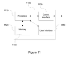
- FIG 11 schematically illustrates an exemplifying apparatus 1100 upon which an embodiment of the invention may be implemented.
- the apparatus 1100 as illustrated in Figure 11 provides a diagram of exemplary components of an apparatus, which is capable of operating as or providing the gesture the audio pre-processor 220, 520 and/or the audio mixer 250 (or the audio processing entity 900) according to an embodiment.
- the apparatus 1100 comprises a processor 1110, a memory 1120 and a communication interface 1130, such as a network card or a network adapter enabling wireless or wireline communication with another apparatus and/or radio transceiver enabling wireless communication with another apparatus over radio frequencies.
- the processor 1110 is configured to read from and write to the memory 1120.
- the memory 1120 may, for example, act as the memory for storing the source audio signals 215, the primary audio signals 225, the direction indications 226, the secondary audio signal(s) 227 and/or the audio objects 255.
- the apparatus 1100 may further comprise a user interface 1140 for providing data, commands and/or other input to the processor 1110 and/or for receiving data or other output from the processor 1110, the user interface 1140 comprising for example one or more of a display, a keyboard or keys, a mouse or a respective pointing device, a touchscreen, etc.
- the apparatus 1100 may comprise further components not illustrated in the example of Figure 11 .
- processor 1110 is presented in the example of Figure 11 as a single component, the processor 1110 may be implemented as one or more separate components.
- memory 1120 in the example of Figure 11 is illustrated as a single component, the memory 1120 may be implemented as one or more separate components, some or all of which may be integrated/removable and/or may provide permanent / semi-permanent/ dynamic/cached storage.
- the apparatus 1100 may be embodied for example as a mobile phone, a digital camera, a digital video camera, a music player, a gaming device, a laptop computer, a desktop computer, a personal digital assistant (PDA), a tablet computer, etc.-basically as any apparatus that is able to process captured source audio signals 215 or that may be (re-)configured to be able to process captured source audio signals 215.
- PDA personal digital assistant
- the memory 1120 may store a computer program 1150 comprising computer-executable instructions that control the operation of the apparatus 1100 when loaded into the processor 1110.
- the computer program 1150 may include one or more sequences of one or more instructions.
- the computer program 1150 may be provided as a computer program code.
- the processor 1110 is able to load and execute the computer program 1150 by reading the one or more sequences of one or more instructions included therein from the memory 1120.
- the one or more sequences of one or more instructions may be configured to, when executed by one or more processors, cause an apparatus, for example the apparatus 1100, to implement the operations, procedures and/or functions described hereinbefore in context of the audio pre-processor 220, 520 and/or the audio mixer 250 (or the audio processing entity 900).
- the apparatus 1100 may comprise at least one processor 1110 and at least one memory 1120 including computer program code for one or more programs, the at least one memory 1120 and the computer program code configured to, with the at least one processor 1110, cause the apparatus 1100 to perform the operations, procedures and/or functions described hereinbefore in context of the audio pre-processor 220, 520 and/or the audio mixer 250 (or the audio processing entity 900).
- the computer program 1150 may be provided at the apparatus 1100 via any suitable delivery mechanism.
- the delivery mechanism may comprise at least one computer readable non-transitory medium having program code stored thereon, the program code which when executed by an apparatus cause the apparatus at least implement processing to carry out the operations, procedures and/or functions described hereinbefore in context of the audio pre-processor 220, 520 and/or the audio mixer 250 (or the audio processing entity 900).
- the delivery mechanism may be for example a computer readable storage medium, a computer program product, a memory device a record medium such as a CD-ROM or DVD or another article of manufacture that tangibly embodies the computer program 1150.
- the delivery mechanism may be a signal configured to reliably transfer the computer program 1150.
- references to a processor should not be understood to encompass only programmable processors, but also dedicated circuits such as field-programmable gate arrays (FPGA), application specific circuits (ASIC), signal processors, etc.Features described in the preceding description may be used in combinations other than the combinations explicitly described. Although functions have been described with reference to certain features, those functions may be performable by other features whether described or not. Although features have been described with reference to certain embodiments, those features may also be present in other embodiments whether described or not.
- FPGA field-programmable gate arrays
- ASIC application specific circuits
Landscapes
- Engineering & Computer Science (AREA)
- Physics & Mathematics (AREA)
- Signal Processing (AREA)
- Acoustics & Sound (AREA)
- Audiology, Speech & Language Pathology (AREA)
- Health & Medical Sciences (AREA)
- Computational Linguistics (AREA)
- Human Computer Interaction (AREA)
- Multimedia (AREA)
- Mathematical Physics (AREA)
- Spectroscopy & Molecular Physics (AREA)
- Quality & Reliability (AREA)
- Stereophonic System (AREA)
Applications Claiming Priority (1)
| Application Number | Priority Date | Filing Date | Title |
|---|---|---|---|
| GB1310597.8A GB2515089A (en) | 2013-06-14 | 2013-06-14 | Audio Processing |
Publications (1)
| Publication Number | Publication Date |
|---|---|
| EP2824662A1 true EP2824662A1 (fr) | 2015-01-14 |
Family
ID=48914543
Family Applications (1)
| Application Number | Title | Priority Date | Filing Date |
|---|---|---|---|
| EP14171647.2A Withdrawn EP2824662A1 (fr) | 2013-06-14 | 2014-06-09 | Traitement audio |
Country Status (3)
| Country | Link |
|---|---|
| US (1) | US20140372107A1 (fr) |
| EP (1) | EP2824662A1 (fr) |
| GB (1) | GB2515089A (fr) |
Cited By (1)
| Publication number | Priority date | Publication date | Assignee | Title |
|---|---|---|---|---|
| FR3112016A1 (fr) * | 2020-06-30 | 2021-12-31 | Fondation B-Com | Procédé de conversion d’un premier ensemble de signaux représentatifs d’un champ sonore en un second ensemble de signaux et dispositif électronique associé |
Families Citing this family (11)
| Publication number | Priority date | Publication date | Assignee | Title |
|---|---|---|---|---|
| CN106297820A (zh) | 2015-05-14 | 2017-01-04 | 杜比实验室特许公司 | 具有基于迭代加权的源方向确定的音频源分离 |
| CN105070304B (zh) * | 2015-08-11 | 2018-09-04 | 小米科技有限责任公司 | 实现对象音频录音的方法及装置、电子设备 |
| US10952011B1 (en) * | 2015-09-01 | 2021-03-16 | Ahmet Zappa | Systems and methods for psychoacoustic processing of audio material |
| US9886965B1 (en) * | 2015-09-01 | 2018-02-06 | Zappa Ahmet | Systems and methods for psychoacoustic processing of audio material |
| WO2017050398A1 (fr) * | 2015-09-25 | 2017-03-30 | Fraunhofer-Gesellschaft zur Förderung der angewandten Forschung e.V. | Codeur, décodeur et procédés pour la commutation avec adaptation au signal du rapport de chevauchement dans le codage audio par transformation |
| US9978381B2 (en) * | 2016-02-12 | 2018-05-22 | Qualcomm Incorporated | Encoding of multiple audio signals |
| US10217468B2 (en) * | 2017-01-19 | 2019-02-26 | Qualcomm Incorporated | Coding of multiple audio signals |
| JP7224302B2 (ja) | 2017-05-09 | 2023-02-17 | ドルビー ラボラトリーズ ライセンシング コーポレイション | マルチチャネル空間的オーディオ・フォーマット入力信号の処理 |
| EP3588495A1 (fr) * | 2018-06-22 | 2020-01-01 | FRAUNHOFER-GESELLSCHAFT zur Förderung der angewandten Forschung e.V. | Codage audio multicanal |
| TWI866996B (zh) | 2019-06-26 | 2024-12-21 | 美商杜拜研究特許公司 | 具有改善頻率解析度的低延遲音訊濾波器組 |
| IL290390B2 (en) | 2019-09-03 | 2025-05-01 | Dolby Laboratories Licensing Corp | Audio filter array with decoupling elements |
Citations (3)
| Publication number | Priority date | Publication date | Assignee | Title |
|---|---|---|---|---|
| US6130949A (en) * | 1996-09-18 | 2000-10-10 | Nippon Telegraph And Telephone Corporation | Method and apparatus for separation of source, program recorded medium therefor, method and apparatus for detection of sound source zone, and program recorded medium therefor |
| EP2249334A1 (fr) * | 2009-05-08 | 2010-11-10 | Fraunhofer-Gesellschaft zur Förderung der angewandten Forschung e.V. | Transcodeur de format audio |
| US20130044884A1 (en) * | 2010-11-19 | 2013-02-21 | Nokia Corporation | Apparatus and Method for Multi-Channel Signal Playback |
Family Cites Families (4)
| Publication number | Priority date | Publication date | Assignee | Title |
|---|---|---|---|---|
| US9009057B2 (en) * | 2006-02-21 | 2015-04-14 | Koninklijke Philips N.V. | Audio encoding and decoding to generate binaural virtual spatial signals |
| MX2011011399A (es) * | 2008-10-17 | 2012-06-27 | Univ Friedrich Alexander Er | Aparato para suministrar uno o más parámetros ajustados para un suministro de una representación de señal de mezcla ascendente sobre la base de una representación de señal de mezcla descendete, decodificador de señal de audio, transcodificador de señal de audio, codificador de señal de audio, flujo de bits de audio, método y programa de computación que utiliza información paramétrica relacionada con el objeto. |
| KR101600354B1 (ko) * | 2009-08-18 | 2016-03-07 | 삼성전자주식회사 | 사운드에서 오브젝트 분리 방법 및 장치 |
| DE102010030534A1 (de) * | 2010-06-25 | 2011-12-29 | Iosono Gmbh | Vorrichtung zum Veränderung einer Audio-Szene und Vorrichtung zum Erzeugen einer Richtungsfunktion |
-
2013
- 2013-06-14 GB GB1310597.8A patent/GB2515089A/en not_active Withdrawn
-
2014
- 2014-06-06 US US14/298,809 patent/US20140372107A1/en not_active Abandoned
- 2014-06-09 EP EP14171647.2A patent/EP2824662A1/fr not_active Withdrawn
Patent Citations (4)
| Publication number | Priority date | Publication date | Assignee | Title |
|---|---|---|---|---|
| US6130949A (en) * | 1996-09-18 | 2000-10-10 | Nippon Telegraph And Telephone Corporation | Method and apparatus for separation of source, program recorded medium therefor, method and apparatus for detection of sound source zone, and program recorded medium therefor |
| EP2249334A1 (fr) * | 2009-05-08 | 2010-11-10 | Fraunhofer-Gesellschaft zur Förderung der angewandten Forschung e.V. | Transcodeur de format audio |
| US20130044884A1 (en) * | 2010-11-19 | 2013-02-21 | Nokia Corporation | Apparatus and Method for Multi-Channel Signal Playback |
| WO2013024200A1 (fr) | 2011-08-15 | 2013-02-21 | Nokia Corporation | Appareil et procédé pour la lecture d'un signal à canaux multiples |
Non-Patent Citations (5)
| Title |
|---|
| "Authoring for Dolby® Atmos Cinema Sound Manual", pages: 13 - 26440,26 |
| "ISO/IEC 23003-2 - Information technology -- MPEG audio technologies -- Part 2: Spatial Audio Object Coding (SAOC", 6 October 2010 |
| AVENDANO C: "Frequency-domain source identification and manipulation in stereo mixes for enhancement, suppression and re-panning applications", APPLICATIONS OF SIGNAL PROCESSING TO AUDIO AND ACOUSTICS, 2003 IEEE WO RKSHOP ON. NEW PALTZ, NY, USA OCT,. 19-22, 2003, PISCATAWAY, NJ, USA,IEEE, 19 October 2003 (2003-10-19), pages 55 - 58, XP010696451, ISBN: 978-0-7803-7850-6, DOI: 10.1109/ASPAA.2003.1285818 * |
| BERT VAN DAELE; WILFRIED VAN BAELEN, AURO-3D OCTOPUS CODEC, PRINCIPLES BEHIND A REVOLUTIONARY CODEC, 17 November 2011 (2011-11-17) |
| ENGDEGARD J ET AL: "Spatial Audio Object Coding (SAOC) - The Upcoming MPEG Standard on Parametric Object Based Audio Coding", JOURNAL OF THE AUDIO ENGINEERING SOCIETY, AUDIO ENGINEERING SOCIETY, NEW YORK, NY, US, no. Paper Number: 7377, 17 May 2008 (2008-05-17), pages 1 - 16, XP002685475, ISSN: 0004-7554 * |
Cited By (2)
| Publication number | Priority date | Publication date | Assignee | Title |
|---|---|---|---|---|
| FR3112016A1 (fr) * | 2020-06-30 | 2021-12-31 | Fondation B-Com | Procédé de conversion d’un premier ensemble de signaux représentatifs d’un champ sonore en un second ensemble de signaux et dispositif électronique associé |
| EP3934282A1 (fr) * | 2020-06-30 | 2022-01-05 | Fondation B-COM | Procédé de conversion d'un premier ensemble de signaux représentatifs d'un champ sonore en un second ensemble de signaux et dispositif électronique associé |
Also Published As
| Publication number | Publication date |
|---|---|
| GB201310597D0 (en) | 2013-07-31 |
| GB2515089A (en) | 2014-12-17 |
| US20140372107A1 (en) | 2014-12-18 |
Similar Documents
| Publication | Publication Date | Title |
|---|---|---|
| EP2824662A1 (fr) | Traitement audio | |
| US20240007814A1 (en) | Determination Of Targeted Spatial Audio Parameters And Associated Spatial Audio Playback | |
| US11832080B2 (en) | Spatial audio parameters and associated spatial audio playback | |
| CN107925815B (zh) | 空间音频处理装置 | |
| EP3542546B1 (fr) | Analyse de métadonnées spatiales à partir de multiples microphones possédant une géométrie asymétrique dans des dispositifs | |
| US9351070B2 (en) | Positional disambiguation in spatial audio | |
| KR101480258B1 (ko) | 미리 계산된 참조 곡선을 이용한 입력 신호 분해 장치 및 방법 | |
| US10477335B2 (en) | Converting multi-microphone captured signals to shifted signals useful for binaural signal processing and use thereof | |
| US11350213B2 (en) | Spatial audio capture | |
| CN105264911A (zh) | 音频设备 | |
| US20250119700A1 (en) | Audio processing | |
| EP3318070B1 (fr) | Détermination d'angles d'azimut et d'élévation à partir d'enregistrements en stéréo | |
| US11032639B2 (en) | Determining azimuth and elevation angles from stereo recordings | |
| HK1255002B (en) | Determining azimuth and elevation angles from stereo recordings |
Legal Events
| Date | Code | Title | Description |
|---|---|---|---|
| 17P | Request for examination filed |
Effective date: 20140609 |
|
| AK | Designated contracting states |
Kind code of ref document: A1 Designated state(s): AL AT BE BG CH CY CZ DE DK EE ES FI FR GB GR HR HU IE IS IT LI LT LU LV MC MK MT NL NO PL PT RO RS SE SI SK SM TR |
|
| AX | Request for extension of the european patent |
Extension state: BA ME |
|
| PUAI | Public reference made under article 153(3) epc to a published international application that has entered the european phase |
Free format text: ORIGINAL CODE: 0009012 |
|
| RAP1 | Party data changed (applicant data changed or rights of an application transferred) |
Owner name: NOKIA TECHNOLOGIES OY |
|
| R17P | Request for examination filed (corrected) |
Effective date: 20150702 |
|
| RBV | Designated contracting states (corrected) |
Designated state(s): AL AT BE BG CH CY CZ DE DK EE ES FI FR GB GR HR HU IE IS IT LI LT LU LV MC MK MT NL NO PL PT RO RS SE SI SK SM TR |
|
| 17Q | First examination report despatched |
Effective date: 20160706 |
|
| STAA | Information on the status of an ep patent application or granted ep patent |
Free format text: STATUS: THE APPLICATION IS DEEMED TO BE WITHDRAWN |
|
| 18D | Application deemed to be withdrawn |
Effective date: 20161117 |