EP2824748A1 - Cadre de cellule de distribution d'écoulement amélioré et batterie à flux redox ayant celui-ci - Google Patents
Cadre de cellule de distribution d'écoulement amélioré et batterie à flux redox ayant celui-ci Download PDFInfo
- Publication number
- EP2824748A1 EP2824748A1 EP14176770.7A EP14176770A EP2824748A1 EP 2824748 A1 EP2824748 A1 EP 2824748A1 EP 14176770 A EP14176770 A EP 14176770A EP 2824748 A1 EP2824748 A1 EP 2824748A1
- Authority
- EP
- European Patent Office
- Prior art keywords
- channel
- channels
- cell frame
- buffer
- electrolyte
- Prior art date
- Legal status (The legal status is an assumption and is not a legal conclusion. Google has not performed a legal analysis and makes no representation as to the accuracy of the status listed.)
- Granted
Links
Images


Classifications
-
- H—ELECTRICITY
- H01—ELECTRIC ELEMENTS
- H01M—PROCESSES OR MEANS, e.g. BATTERIES, FOR THE DIRECT CONVERSION OF CHEMICAL ENERGY INTO ELECTRICAL ENERGY
- H01M8/00—Fuel cells; Manufacture thereof
- H01M8/02—Details
-
- H—ELECTRICITY
- H01—ELECTRIC ELEMENTS
- H01M—PROCESSES OR MEANS, e.g. BATTERIES, FOR THE DIRECT CONVERSION OF CHEMICAL ENERGY INTO ELECTRICAL ENERGY
- H01M8/00—Fuel cells; Manufacture thereof
- H01M8/04—Auxiliary arrangements, e.g. for control of pressure or for circulation of fluids
- H01M8/04276—Arrangements for managing the electrolyte stream, e.g. heat exchange
-
- H—ELECTRICITY
- H01—ELECTRIC ELEMENTS
- H01M—PROCESSES OR MEANS, e.g. BATTERIES, FOR THE DIRECT CONVERSION OF CHEMICAL ENERGY INTO ELECTRICAL ENERGY
- H01M8/00—Fuel cells; Manufacture thereof
- H01M8/002—Shape, form of a fuel cell
- H01M8/006—Flat
-
- H—ELECTRICITY
- H01—ELECTRIC ELEMENTS
- H01M—PROCESSES OR MEANS, e.g. BATTERIES, FOR THE DIRECT CONVERSION OF CHEMICAL ENERGY INTO ELECTRICAL ENERGY
- H01M8/00—Fuel cells; Manufacture thereof
- H01M8/02—Details
- H01M8/0271—Sealing or supporting means around electrodes, matrices or membranes
- H01M8/0273—Sealing or supporting means around electrodes, matrices or membranes with sealing or supporting means in the form of a frame
-
- H—ELECTRICITY
- H01—ELECTRIC ELEMENTS
- H01M—PROCESSES OR MEANS, e.g. BATTERIES, FOR THE DIRECT CONVERSION OF CHEMICAL ENERGY INTO ELECTRICAL ENERGY
- H01M8/00—Fuel cells; Manufacture thereof
- H01M8/18—Regenerative fuel cells, e.g. redox flow batteries or secondary fuel cells
- H01M8/184—Regeneration by electrochemical means
- H01M8/188—Regeneration by electrochemical means by recharging of redox couples containing fluids; Redox flow type batteries
-
- H—ELECTRICITY
- H01—ELECTRIC ELEMENTS
- H01M—PROCESSES OR MEANS, e.g. BATTERIES, FOR THE DIRECT CONVERSION OF CHEMICAL ENERGY INTO ELECTRICAL ENERGY
- H01M8/00—Fuel cells; Manufacture thereof
- H01M8/20—Indirect fuel cells, e.g. fuel cells with redox couple being irreversible
-
- H—ELECTRICITY
- H01—ELECTRIC ELEMENTS
- H01M—PROCESSES OR MEANS, e.g. BATTERIES, FOR THE DIRECT CONVERSION OF CHEMICAL ENERGY INTO ELECTRICAL ENERGY
- H01M8/00—Fuel cells; Manufacture thereof
- H01M8/24—Grouping of fuel cells, e.g. stacking of fuel cells
- H01M8/2455—Grouping of fuel cells, e.g. stacking of fuel cells with liquid, solid or electrolyte-charged reactants
-
- Y—GENERAL TAGGING OF NEW TECHNOLOGICAL DEVELOPMENTS; GENERAL TAGGING OF CROSS-SECTIONAL TECHNOLOGIES SPANNING OVER SEVERAL SECTIONS OF THE IPC; TECHNICAL SUBJECTS COVERED BY FORMER USPC CROSS-REFERENCE ART COLLECTIONS [XRACs] AND DIGESTS
- Y02—TECHNOLOGIES OR APPLICATIONS FOR MITIGATION OR ADAPTATION AGAINST CLIMATE CHANGE
- Y02E—REDUCTION OF GREENHOUSE GAS [GHG] EMISSIONS, RELATED TO ENERGY GENERATION, TRANSMISSION OR DISTRIBUTION
- Y02E60/00—Enabling technologies; Technologies with a potential or indirect contribution to GHG emissions mitigation
- Y02E60/30—Hydrogen technology
- Y02E60/50—Fuel cells
Definitions
- the present invention relates to a redox flow battery, and more particularly, to a cell frame channel design capable of efficiently distributing an electrolyte throughout the entire electrode area and efficiently distributing the electrolyte at various flow rate conditions at which a battery is operated.
- Uniform distribution of an electrolyte is an important factor associated with cell performance and efficiency in increasing a size of a redox flow battery.
- a flow velocity of the electrolyte should be faster than the existing operation condition (flow rate per electrode area: 0.5cc/(min*cm 2 ), discharge current per electrode area: 80mA/cm 2 ) but it is impossible to uniformly distribute the electrolyte using a longitudinal channel formed vertically to a transverse channel in the existing battery.
- FIG. 2 is a diagram showing a channel structure of the electrolyte-flowing device for a redox flow battery according to the related art. As shown in FIG. 2 , a second longitudinal channel 507 is installed vertically to a second transverse channel 508.
- the present invention has been made in an effort to provide a channel design in which an electrolyte is distributed at the same pressure condition and the same channel length for efficient distribution of the electrolyte in a large size redox flow battery, an a channel structure in which a buffer section capable of allowing a velocity of the electrolyte to be uniform and a distribution section are mixed at a fast flow velocity condition of the electrolyte.
- the present invention has been made in an effort to provide a cell design including a block for preventing a jet flow of an electrolyte injected at a high pressure.
- a cell frame of a redox flow battery comprising: an electrolyte inlet part disposed adjacent to a side of an electrode of the redox flow battery; an electrolyte outlet part disposed adjacent to the other side of the electrode; a multi-step distribution channel connected to the electrolyte inlet part, deployed in a transverse direction of the cell frame, and divided into a plurality of channels; multi-step buffer channels, each of which is connected to one of the divided channels of the distribution channel, deployed in a longitudinal direction of the cell frame, and divided into a plurality of sub-channels, wherein a width of each sub-channel is increased toward the electrode; a mixing zone disposed between the buffer channels and the electrode, and configured to mix electrolytes flowed from the buffer channels; and a mixing block disposed in the mixing zone, and configured to distribute and buffer the electrolytes in the mixing zone.
- the distribution channel may be divided into the plurality of channels at a divisional point, wherein a width of the distribution channel before the divisional point is same as a sum of widths of the divided channels of the distribution channel after the division point.
- Each of the buffer channels comprises at least one step-divisional point and has a shape in which a sum of widths of the sub-channels after the step-divisional point is greater than a width of the buffer channel connected to the sub-channels, it is preferable that a sum of widths of the sub-channels divided at an (n+1)-th step divisional point is greater than a sum of widths of sub-channels divided at an n-th step divisional point.
- a ratio between a width of a buffer channel before the step-divisional point and a sum of widths of sub-channels after the step-divisional point is in a range of 1:1.01 to 1:4.
- a width of an outlet of the buffer channel is in a range of 5 to 30 times a width of an inlet of the buffer channel, and more preferably, the width of the outlet is in a range of 10 to 20 times the width of the inlet.
- the outlet is connected to the mixing zone, and the inlet is connected to the corresponding divided channel of the distribution channel.
- the mixing zone has the same width as that of the electrode, and one or more mixing blocks for preventing the electrolyte from being injected at a high pressure are arranged in the mixing zone so as to uniformly divide the mixing zone. It is preferable that the mixing block is positioned so that the mixing zone is uniformly divided for uniform re-distribution of the electrolyte and a central portion of the mixing block is overlapped with a central portion of each buffer channel, thereby preventing highpressure injection of the electrolyte.
- a cross section of the mixing block has a circular shape or a polygonal shape.
- An area occupied by the mixing block in the mixing zone is in a range of 10% to 50% of the entire area of the mixing zone.
- one or more multi-step distribution channels have the same channel lengths, and all of the buffer channels have the same lengths.
- a redox flow battery including: a cell frame of a redox flow battery; and an electrode supplied with an electrolyte from the cell frame, wherein the cell frame of a redox flow battery includes: an electrolyte inlet part disposed adjacent to a side of an electrode of the redox flow battery; an electrolyte outlet part disposed adjacent to the other side of the electrode a multi-step distribution channel connected to the electrolyte inlet part, deployed in a transverse direction of the cell frame, and divided into a plurality of channels; multi-step buffer channels, each of which is connected to one of the divided channels of the distribution channel, deployed in a longitudinal direction of the cell frame, and divided into a plurality of sub-channels, wherein a width of each sub-channel is increased toward the electrode; a mixing zone disposed between the buffer channels and the electrode, and configured to mix electrolytes flowed from the buffer channels; and a mixing block disposed in the mixing zone, and configured to
- Uniform distribution of an electrolyte is an important factor associated with cell performance and efficiency in increasing a size of a redox flow battery.
- uniformly distributing the electrolyte in a shape of an electrolyte flow channel of a cell frame of an existing redox flow battery.
- a flow velocity of the electrolyte should be faster than the existing operation condition, but a longitudinal channel formed vertically to a transverse channel in the existing battery forms a jet flow of the electrolyte injected at a high pressure as shown in FIG. 2 , thereby deteriorating cell efficiency.
- FIG. 3 shows velocity distribution when an electrolyte is introduced at a high velocity in a cell frame of a redox flow battery according to the related art.
- the jet flow is formed at some region, such that an electrode area may not be entirely utilized, thereby decreasing the cell efficiency.
- the present invention is to provide a channel design in which an electrolyte is distributed at the same pressure condition and the same channel length for efficient distribution of the electrolyte in a large size redox flow battery, an a channel structure in which a buffer section capable of allowing a rate of the electrolyte to be uniform and a distribution section are mixed at a fast flow velocity condition of the electrolyte.
- the present invention is characterized in that a mixing block for preventing the jet flow of the electrolyte injected at a high pressure is included.
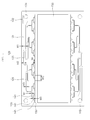
- FIG. 1 is a diagram showing a rear surface of the cell frame of the redox flow battery according to an exemplary embodiment of the present invention
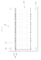
- FIG. 4 is a diagram showing a front surface of the cell frame of the redox flow battery according to the exemplary embodiment of the present invention.
- the cell frame 100 of the redox flow battery according to the exemplary embodiment of the present invention may serve to uniformly supply an electrolyte to an electrode 200.
- the cell frame 100 is disposed in a shape enclosing a peripheral portion of the electrode 200, and in the case of the exemplary embodiment shown in FIGS. 1 and 4 , the cell frame 100 has a structure in which the electrolyte is introduced downwardly from the electrode 200, performs a reaction in the electrode 200, and then, is discharged upwardly from the electrode 200.
- the structure of the cell frame 100 is not limited thereto, but on the contrary, the cell frame 100 may have a structure in which the electrolyte is introduced upwardly and discharged downwardly.
- an electrolyte inlet part 102 and an electrolyte outlet part 104 are formed at a right upper end and a left lower end of the cell frame 100, respectively.
- the electrolyte inlet part and the electrolyte outlet part 102 and 104 are formed in a shape of a through hole penetrating through the cell frame 100.
- the electrolyte introduced through the electrolyte inlet part 102 at the left lower end is supplied to the electrode 200 through a distribution channel 120, a buffer channel 140, and a mixing zone 160.
- the distribution channel 120, the buffer channel 140, and the mixing zone 160 are formed on and beneath of the electrode 200 in a symmetrical shape.
- the distribution channel 120 is connected to the electrolyte inlet part 102 to serve to divide the electrolyte into a plurality of channels.
- the distribution channel 120 divides the electrolyte and uniformly disperses the electrolyte to thereby flow the electrolyte.
- the distribution channel 120 is designed in order to distribute the electrolyte to the entire electrode area, and only in the case in which a pressure drop ( ⁇ P) applied to each distribution channel 120 is equal, uniform distribution of the electrolyte may be induced.
- the electrolyte may be biased toward a portion at which the pressure drop ( ⁇ P) is small, and the electrolyte is not distributed to the entire surface of the electrode, such that the cell efficiency may be deteriorated.
- Total lengths of each distribution channel is need to be equal to each other, and it is preferable in view of uniform distribution that when the distribution channel is divided, a division direction of all the distribution channels is a transverse direction.
- a bent portion of the distribution channel has a round shape. The reason is that in the case in which the channel is bent at a right angle, the pressure drop may be increased.
- a channel width before division and a sum of channel widths after division are the same as each other. The reason is that in the case in which the sum of the divided channel widths is smaller than the width of the channel before division, the pressure drop is significantly generated in the channel itself, a larger output is required in a pump in order to secure a predetermined flow rate, such that power consumption is increased.
- the distribution channel 120 includes a flow stabilization section 122 connected to the electrolyte inlet part 102 to stabilize a flow of the electrolyte supplied from the electrolyte inlet part 102, a first channel 121 connected to the flow stabilization section 122 to maintain a first channel width w1, a second channel 123 divided from the first channel 121 so as to have a second channel width w2, and a third channel 125 divided from the second channel 123 so as to have a third channel width w3.
- the distribution channel 120 may be divided from the first channel 121 into two second channels 123, and two second channels 123 are divided into four third channels 125.
- the second channel width w2 is a half of the first channel width w1
- the third channel width w3 is a half of the second channel width w2. That is, even though the distribution channel is divided, the entire channel width is constantly maintained. Therefore, a constant flow velocity is maintained from the first channel 121 up to the third channel 125 in the distribution channel 120, and a stable flow of the electrolyte may be formed.
- the distribution channel 120 according to the exemplary embodiment shown in FIG. 1 has four routes to the buffer channel 140, and in each of the routes, lengths of the routes are the same as each other. The reason is to allow the electrolyte distributed through the distribution channel 120 to flow at the same condition.
- the buffer channel 140 is a channel connecting the distribution channel 120 and the mixing zone 160.
- the buffer channel 140 is formed so that a channel width is increased toward a downstream portion (a lower portion in the flow) unlike the distribution channel 120, such that the buffer channel 140 serves to allow the velocity to be uniform while decreasing the flow velocity.
- the buffer channel 140 may be configured as a multi-step form, and it is advantageous in view of a buffer effect that a channel width increased in a multi-step is increased at a ratio smaller than an expansion width WO of a final buffer channel connected to the mixing zone 160.
- An outlet width WO of the final buffer channel is in a range of, preferably, 5 to 30 times, and more preferably 10 to 20 times an inlet width WI of the buffer channel.
- the inlet width WI of the buffer channel means a channel width at a position at which the buffer channel starts
- the outlet width WO of the buffer channel means a channel width at a position at which the buffer channel ends.
- a sum of widths of buffer channels divided at an (n+1)-th step is larger than a sum of widths of buffer channels divided at an n-th step.
- a ratio between a width of a buffer channel before division and a sum of widths of buffer channels after division at a specific step is in a range of 1:1.01 to 1:4.
- the multi-step buffer channel is to distribute the electrolyte to the entire electrode area and improve the buffer effect, and in the case in which the ratio of the channel width is more than 1:4, distribution efficiency may be deteriorated.
- the reason is that a channel expanded at a ratio more than 1:4 instantly causes a pressure drop, thereby deteriorating distribution efficiency.
- the final buffer channel may be expanded so that the outlet width thereof is 5 to 30 times the inlet width thereof, more preferably, 10 to 20 times the inlet width thereof.
- the outlet width of the final buffer channel is less than 5 times the inlet width thereof, at the time of cell operation at a fast flow rate range (flow rate per electrode area >1cc/(min*cm 2 )), the buffer effect of the electrolyte is insignificant, thereby making it possible to cause a jet flow, and in the case in which the final buffer channel is more than 30 times, it is difficult to operate the battery while adjusting the flow rate at a slow flow rate range (flow rate per electrode area ⁇ 0.5cc/(min*cm 2 )).
- the buffer channel 140 includes a fourth channel 141 divided from the third channel of the distribution channel 120 so as to have a fourth channel width w4, a fifth channel 143 divided from the fourth channel 141, and a sixth channel 145 divided from the fifth channel 143 and expanded so that a channel width thereof is 10 to 20 times a fifth channel width w5.
- a penetration channel 150 is formed at an outlet portion of the sixth channel 145, such that the electrolyte flowing along the distribution channel 120 and the buffer channel 140 formed at the rear surface of the cell frame 100 flows to the front surface of the cell frame 100.
- the penetration channel 150 is connected to the outlet portion of the sixth channel 145, and a width of the penetration channel 150 and the outlet width of the sixth channel 145 are the same as each other.
- the penetration channel 150 has the same width as a width of the mixing zone 160 at the front surface, and the mixing zone 160 is formed so as to have the same width as that of the electrode.
- the mixing zone 160 is formed at the front surface of the cell frame 100, and mixing blocks 162 are provided in the mixing zone 160.
- a mixture channel 164 is formed between the mixing blocks 162 in the mixing zone 160.
- the mixing block 162 has a predetermined thickness, and a cross-section thereof has a circular or polygonal shape.
- the mixing blocks 162 are uniformly arranged in the mixing zone 160, and the mixture channel 164 is formed between the mixing blocks 162.
- an area occupied by the mixing block 162 in the mixing zone 160 is 10 to 50% of the entire area of the mixing zone 160.
- the reason is that in the case in which the area of the mixing block is equal to or less than 10% of the area of the mixing zone, it is difficult to uniformly control the movement velocity of the electrolyte at the time of operation at a fast flow rate range (flow rate per electrode area >1cc/(min*cm 2 ) ) , and in the case in which the area of the mixing block 162 is more than 50%, the mixture channel 164 becomes narrow, such that the velocity of the electrolyte may be locally increased.
- the pressure drop at a given flow rate may be decreased, and at the same time, the buffer effect may be obtained.
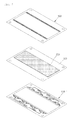
- FIG. 5 is a configuration diagram showing a coupling relation of the cell frame of the redox flow battery according to an exemplary embodiment of the present invention.
- the distribution channel (120 of FIG. 1 ) and the buffer channel (140 of FIG. 1 ) are formed in a groove shape at the rear surface, and a central frame 300 is adhered while covering the distribution channel 120 and the buffer channel 140 formed in the groove shape.
- An electrode plate 200 is adhered to the central frame 300.
- a cell frame 100-1 in which an electrolyte having a different polarity flows is adhered to an opposite side of the central frame 300 while sharing the central frame 300 and the electrode plate 200.
- the cell frame providing a flow path of the electrolyte is significantly important in view of improving battery efficiency through efficient distribution of the electrolyte.
- efficiency is deteriorated due to nonuniform distribution of the electrolyte, that is, a phenomenon that a flow of the electrolyte introduced at a high pressure is concentrated at some section at which the pressure of the electrolyte is relieved.
- the present invention solves this problem, such that the electrolyte may be uniformly distributed, and the jet flow may not be generated.
- the cell frame according to the present invention is to uniformly distribute the electrolyte and implement the buffer effect.
- the electrolyte is uniformly distributed to all of the sections, such that electrolyte may maximally utilize the electrode area, thereby increasing battery efficiency. Maximization of electrode area utilization may decrease a charging time and a discharging time, and at the time of using power with high output, battery efficiency may be maintained through uniform distribution of the electrolyte at the required fast flow velocity condition.
- the jet flow is not generated and the electrolyte may be uniformly distributed, even at the fast flow velocity condition of the electrolyte, by disposing the mixing zone and the mixing block while distributing the electrolyte through the channels having the same channel length as each other under the same pressure condition.
- the flow of the electrolyte is not concentrated on some section but uniformly distributed, such that the electrode area may be maximally utilized, thereby improving battery efficiency.
Landscapes
- Life Sciences & Earth Sciences (AREA)
- Engineering & Computer Science (AREA)
- Manufacturing & Machinery (AREA)
- Sustainable Development (AREA)
- Sustainable Energy (AREA)
- Chemical & Material Sciences (AREA)
- Chemical Kinetics & Catalysis (AREA)
- Electrochemistry (AREA)
- General Chemical & Material Sciences (AREA)
- Fuel Cell (AREA)
Applications Claiming Priority (2)
| Application Number | Priority Date | Filing Date | Title |
|---|---|---|---|
| KR1020130082169A KR101586117B1 (ko) | 2013-07-12 | 2013-07-12 | 레독스 흐름 전지 및 셀 프레임 |
| KR20130082065A KR101459927B1 (ko) | 2013-07-12 | 2013-07-12 | 전해액 분배 효율성을 향상시킨 셀 프레임 및 이를 구비하는 레독스 흐름 전지 |
Publications (2)
| Publication Number | Publication Date |
|---|---|
| EP2824748A1 true EP2824748A1 (fr) | 2015-01-14 |
| EP2824748B1 EP2824748B1 (fr) | 2016-10-12 |
Family
ID=51176204
Family Applications (2)
| Application Number | Title | Priority Date | Filing Date |
|---|---|---|---|
| EP14176770.7A Not-in-force EP2824748B1 (fr) | 2013-07-12 | 2014-07-11 | Cadre de cellule de distribution d'écoulement amélioré et batterie à flux redox ayant celui-ci |
| EP14176678.2A Withdrawn EP2824747A1 (fr) | 2013-07-12 | 2014-07-11 | Batterie à flux redox et cadre de pile |
Family Applications After (1)
| Application Number | Title | Priority Date | Filing Date |
|---|---|---|---|
| EP14176678.2A Withdrawn EP2824747A1 (fr) | 2013-07-12 | 2014-07-11 | Batterie à flux redox et cadre de pile |
Country Status (3)
| Country | Link |
|---|---|
| US (1) | US20150017558A1 (fr) |
| EP (2) | EP2824748B1 (fr) |
| CN (2) | CN104282922B (fr) |
Families Citing this family (7)
| Publication number | Priority date | Publication date | Assignee | Title |
|---|---|---|---|---|
| AU2016391240B2 (en) * | 2016-02-03 | 2021-10-21 | Sumitomo Electric Industries, Ltd. | Redox flow battery |
| KR20190077241A (ko) * | 2016-11-16 | 2019-07-03 | 스미토모덴키고교가부시키가이샤 | 셀 프레임, 셀 스택, 및 레독스 플로우 전지 |
| CN107634241B (zh) * | 2017-08-25 | 2024-03-12 | 清华大学 | 用于液流电池的液流框 |
| CN110970636B (zh) * | 2018-09-29 | 2020-11-27 | 中国科学院大连化学物理研究所 | 一种阴极电极框在锌溴单液流电池中的应用 |
| EP3923390A4 (fr) * | 2019-04-24 | 2023-01-25 | Murata Manufacturing Co., Ltd. | Batterie secondaire |
| TWI781485B (zh) * | 2020-11-30 | 2022-10-21 | 財團法人金屬工業研究發展中心 | 液流電池的流道板 |
| CN116742030B (zh) * | 2023-08-14 | 2023-12-05 | 北京普能世纪科技有限公司 | 一种液流电池用电极及一种液流电池 |
Citations (3)
| Publication number | Priority date | Publication date | Assignee | Title |
|---|---|---|---|---|
| WO2008116248A1 (fr) * | 2007-03-28 | 2008-10-02 | Redflow Pty Ltd | Empilement de pile de batterie à électrolyte circulant |
| WO2012033692A2 (fr) * | 2010-09-08 | 2012-03-15 | Primus Power Corporation | Ensemble d'électrodes métalliques pour batteries à flux |
| KR101176575B1 (ko) | 2012-06-13 | 2012-08-23 | 주식회사 누리플랜 | 레독스 흐름전지용 전해액 유동장치 |
Family Cites Families (9)
| Publication number | Priority date | Publication date | Assignee | Title |
|---|---|---|---|---|
| GB9821156D0 (en) * | 1998-09-29 | 1998-11-25 | Nat Power Plc | Manufacturable electrochemical cell |
| JP2002246061A (ja) * | 2001-02-15 | 2002-08-30 | Sumitomo Electric Ind Ltd | レドックスフロー2次電池用セルフレーム構造およびその製造方法 |
| JP3682244B2 (ja) | 2001-06-12 | 2005-08-10 | 住友電気工業株式会社 | レドックスフロー電池用セルフレーム及びレドックスフロー電池 |
| JP2004319341A (ja) * | 2003-04-17 | 2004-11-11 | Sumitomo Electric Ind Ltd | レドックスフロー電池 |
| AU2003304610A1 (en) * | 2003-12-12 | 2005-06-29 | Lg Electronics Inc. | Bipolar plate of fuel cell |
| PH12013500003A1 (en) * | 2010-06-29 | 2017-08-23 | Squirrel Holdings Ltd | Compact frameless bipolar stack for a multicell electrochemical reactor with planar bipolar electrical interconnects and internal ducting of circulation of electrolyte solutions through all respective cell compartments |
| US9478803B2 (en) * | 2011-06-27 | 2016-10-25 | Primus Power Corporation | Electrolyte flow configuration for a metal-halogen flow battery |
| US8137831B1 (en) * | 2011-06-27 | 2012-03-20 | Primus Power Corporation | Electrolyte flow configuration for a metal-halogen flow battery |
| US9577242B2 (en) * | 2011-08-22 | 2017-02-21 | Ensync, Inc. | Internal header flow divider for uniform electrolyte distribution |
-
2014
- 2014-07-11 EP EP14176770.7A patent/EP2824748B1/fr not_active Not-in-force
- 2014-07-11 US US14/329,311 patent/US20150017558A1/en not_active Abandoned
- 2014-07-11 EP EP14176678.2A patent/EP2824747A1/fr not_active Withdrawn
- 2014-07-14 CN CN201410334553.0A patent/CN104282922B/zh active Active
- 2014-07-14 CN CN201410333941.7A patent/CN104282921A/zh active Pending
Patent Citations (3)
| Publication number | Priority date | Publication date | Assignee | Title |
|---|---|---|---|---|
| WO2008116248A1 (fr) * | 2007-03-28 | 2008-10-02 | Redflow Pty Ltd | Empilement de pile de batterie à électrolyte circulant |
| WO2012033692A2 (fr) * | 2010-09-08 | 2012-03-15 | Primus Power Corporation | Ensemble d'électrodes métalliques pour batteries à flux |
| KR101176575B1 (ko) | 2012-06-13 | 2012-08-23 | 주식회사 누리플랜 | 레독스 흐름전지용 전해액 유동장치 |
Also Published As
| Publication number | Publication date |
|---|---|
| CN104282922A (zh) | 2015-01-14 |
| EP2824748B1 (fr) | 2016-10-12 |
| US20150017558A1 (en) | 2015-01-15 |
| CN104282921A (zh) | 2015-01-14 |
| CN104282922B (zh) | 2017-04-12 |
| EP2824747A1 (fr) | 2015-01-14 |
Similar Documents
| Publication | Publication Date | Title |
|---|---|---|
| EP2824748A1 (fr) | Cadre de cellule de distribution d'écoulement amélioré et batterie à flux redox ayant celui-ci | |
| KR101459927B1 (ko) | 전해액 분배 효율성을 향상시킨 셀 프레임 및 이를 구비하는 레독스 흐름 전지 | |
| CN102646752B (zh) | 交指型共挤设备及用于沉积包括交指型材料的结构的方法 | |
| US20210083303A1 (en) | Flow field plate for fuel cell | |
| CN102646834A (zh) | 交指型电极结构及其形成方法 | |
| CN103503213B (zh) | 燃料电池以及制造金属网的方法 | |
| WO2007134120A3 (fr) | dispositif microfluidique permettant de former des lipoplexes monodispersÉs | |
| GB2555949A (en) | Microfluidic device with longitudinal and transversal liquid barriers for transversal flow mixing | |
| US10722853B2 (en) | Static mixer without mixing baffle sidewalls and associated mixing conduit | |
| CN102989337A (zh) | 静态混合器 | |
| US20170194659A1 (en) | Porous panel for separator of fuel cell | |
| CN105879730A (zh) | 双楔混合挡板和相关联的静态混合器及混合方法 | |
| KR101025386B1 (ko) | 연료 전지를 위한 캐스캐이드 연료 입구 매니폴드 | |
| US20110141844A1 (en) | Static mixer | |
| US20160263546A1 (en) | Micro-channel reactor | |
| CN103137983B (zh) | 多孔电极组、液流半电池和液流电池堆 | |
| CN103117402B (zh) | 多孔电极组、液流半电池和液流电池堆 | |
| CN104924573A (zh) | 用于塑料材料熔体的均化的装置和方法 | |
| CN105298599A (zh) | 混合器及其混合组件 | |
| EP2314959B1 (fr) | Dispositif de pulvérisation d'eau pour machine à glace | |
| RU2383087C2 (ru) | Пластина для топливного элемента | |
| CN117512623A (zh) | 基于鱼刺型流道的电解池流场结构 | |
| US9713802B2 (en) | Method and apparatus for manufacturing liquid microspheres | |
| US9755250B2 (en) | Method of making a fuel cell component having an interdigitated flow field configuration | |
| JP6456052B2 (ja) | 燃料電池用の流路装置、燃料電池並びに燃料電池積層体 |
Legal Events
| Date | Code | Title | Description |
|---|---|---|---|
| 17P | Request for examination filed |
Effective date: 20140711 |
|
| AK | Designated contracting states |
Kind code of ref document: A1 Designated state(s): AL AT BE BG CH CY CZ DE DK EE ES FI FR GB GR HR HU IE IS IT LI LT LU LV MC MK MT NL NO PL PT RO RS SE SI SK SM TR |
|
| AX | Request for extension of the european patent |
Extension state: BA ME |
|
| PUAI | Public reference made under article 153(3) epc to a published international application that has entered the european phase |
Free format text: ORIGINAL CODE: 0009012 |
|
| GRAP | Despatch of communication of intention to grant a patent |
Free format text: ORIGINAL CODE: EPIDOSNIGR1 |
|
| RIC1 | Information provided on ipc code assigned before grant |
Ipc: H01M 8/18 20060101AFI20160422BHEP Ipc: H01M 8/04276 20160101ALI20160422BHEP Ipc: H01M 8/0273 20160101ALI20160422BHEP |
|
| INTG | Intention to grant announced |
Effective date: 20160520 |
|
| GRAS | Grant fee paid |
Free format text: ORIGINAL CODE: EPIDOSNIGR3 |
|
| GRAA | (expected) grant |
Free format text: ORIGINAL CODE: 0009210 |
|
| AK | Designated contracting states |
Kind code of ref document: B1 Designated state(s): AL AT BE BG CH CY CZ DE DK EE ES FI FR GB GR HR HU IE IS IT LI LT LU LV MC MK MT NL NO PL PT RO RS SE SI SK SM TR |
|
| REG | Reference to a national code |
Ref country code: GB Ref legal event code: FG4D |
|
| REG | Reference to a national code |
Ref country code: CH Ref legal event code: EP |
|
| REG | Reference to a national code |
Ref country code: AT Ref legal event code: REF Ref document number: 837226 Country of ref document: AT Kind code of ref document: T Effective date: 20161015 |
|
| REG | Reference to a national code |
Ref country code: IE Ref legal event code: FG4D |
|
| REG | Reference to a national code |
Ref country code: DE Ref legal event code: R096 Ref document number: 602014004169 Country of ref document: DE |
|
| REG | Reference to a national code |
Ref country code: LT Ref legal event code: MG4D |
|
| REG | Reference to a national code |
Ref country code: NL Ref legal event code: MP Effective date: 20161012 |
|
| PG25 | Lapsed in a contracting state [announced via postgrant information from national office to epo] |
Ref country code: LV Free format text: LAPSE BECAUSE OF FAILURE TO SUBMIT A TRANSLATION OF THE DESCRIPTION OR TO PAY THE FEE WITHIN THE PRESCRIBED TIME-LIMIT Effective date: 20161012 |
|
| REG | Reference to a national code |
Ref country code: AT Ref legal event code: MK05 Ref document number: 837226 Country of ref document: AT Kind code of ref document: T Effective date: 20161012 |
|
| PG25 | Lapsed in a contracting state [announced via postgrant information from national office to epo] |
Ref country code: SE Free format text: LAPSE BECAUSE OF FAILURE TO SUBMIT A TRANSLATION OF THE DESCRIPTION OR TO PAY THE FEE WITHIN THE PRESCRIBED TIME-LIMIT Effective date: 20161012 Ref country code: NO Free format text: LAPSE BECAUSE OF FAILURE TO SUBMIT A TRANSLATION OF THE DESCRIPTION OR TO PAY THE FEE WITHIN THE PRESCRIBED TIME-LIMIT Effective date: 20170112 Ref country code: GR Free format text: LAPSE BECAUSE OF FAILURE TO SUBMIT A TRANSLATION OF THE DESCRIPTION OR TO PAY THE FEE WITHIN THE PRESCRIBED TIME-LIMIT Effective date: 20170113 Ref country code: LT Free format text: LAPSE BECAUSE OF FAILURE TO SUBMIT A TRANSLATION OF THE DESCRIPTION OR TO PAY THE FEE WITHIN THE PRESCRIBED TIME-LIMIT Effective date: 20161012 |
|
| PG25 | Lapsed in a contracting state [announced via postgrant information from national office to epo] |
Ref country code: NL Free format text: LAPSE BECAUSE OF FAILURE TO SUBMIT A TRANSLATION OF THE DESCRIPTION OR TO PAY THE FEE WITHIN THE PRESCRIBED TIME-LIMIT Effective date: 20161012 Ref country code: RS Free format text: LAPSE BECAUSE OF FAILURE TO SUBMIT A TRANSLATION OF THE DESCRIPTION OR TO PAY THE FEE WITHIN THE PRESCRIBED TIME-LIMIT Effective date: 20161012 Ref country code: AT Free format text: LAPSE BECAUSE OF FAILURE TO SUBMIT A TRANSLATION OF THE DESCRIPTION OR TO PAY THE FEE WITHIN THE PRESCRIBED TIME-LIMIT Effective date: 20161012 Ref country code: PL Free format text: LAPSE BECAUSE OF FAILURE TO SUBMIT A TRANSLATION OF THE DESCRIPTION OR TO PAY THE FEE WITHIN THE PRESCRIBED TIME-LIMIT Effective date: 20161012 Ref country code: FI Free format text: LAPSE BECAUSE OF FAILURE TO SUBMIT A TRANSLATION OF THE DESCRIPTION OR TO PAY THE FEE WITHIN THE PRESCRIBED TIME-LIMIT Effective date: 20161012 Ref country code: IS Free format text: LAPSE BECAUSE OF FAILURE TO SUBMIT A TRANSLATION OF THE DESCRIPTION OR TO PAY THE FEE WITHIN THE PRESCRIBED TIME-LIMIT Effective date: 20170212 Ref country code: HR Free format text: LAPSE BECAUSE OF FAILURE TO SUBMIT A TRANSLATION OF THE DESCRIPTION OR TO PAY THE FEE WITHIN THE PRESCRIBED TIME-LIMIT Effective date: 20161012 Ref country code: ES Free format text: LAPSE BECAUSE OF FAILURE TO SUBMIT A TRANSLATION OF THE DESCRIPTION OR TO PAY THE FEE WITHIN THE PRESCRIBED TIME-LIMIT Effective date: 20161012 Ref country code: PT Free format text: LAPSE BECAUSE OF FAILURE TO SUBMIT A TRANSLATION OF THE DESCRIPTION OR TO PAY THE FEE WITHIN THE PRESCRIBED TIME-LIMIT Effective date: 20170213 Ref country code: BE Free format text: LAPSE BECAUSE OF FAILURE TO SUBMIT A TRANSLATION OF THE DESCRIPTION OR TO PAY THE FEE WITHIN THE PRESCRIBED TIME-LIMIT Effective date: 20161012 |
|
| REG | Reference to a national code |
Ref country code: DE Ref legal event code: R097 Ref document number: 602014004169 Country of ref document: DE |
|
| PG25 | Lapsed in a contracting state [announced via postgrant information from national office to epo] |
Ref country code: EE Free format text: LAPSE BECAUSE OF FAILURE TO SUBMIT A TRANSLATION OF THE DESCRIPTION OR TO PAY THE FEE WITHIN THE PRESCRIBED TIME-LIMIT Effective date: 20161012 Ref country code: RO Free format text: LAPSE BECAUSE OF FAILURE TO SUBMIT A TRANSLATION OF THE DESCRIPTION OR TO PAY THE FEE WITHIN THE PRESCRIBED TIME-LIMIT Effective date: 20161012 Ref country code: SK Free format text: LAPSE BECAUSE OF FAILURE TO SUBMIT A TRANSLATION OF THE DESCRIPTION OR TO PAY THE FEE WITHIN THE PRESCRIBED TIME-LIMIT Effective date: 20161012 Ref country code: DK Free format text: LAPSE BECAUSE OF FAILURE TO SUBMIT A TRANSLATION OF THE DESCRIPTION OR TO PAY THE FEE WITHIN THE PRESCRIBED TIME-LIMIT Effective date: 20161012 Ref country code: CZ Free format text: LAPSE BECAUSE OF FAILURE TO SUBMIT A TRANSLATION OF THE DESCRIPTION OR TO PAY THE FEE WITHIN THE PRESCRIBED TIME-LIMIT Effective date: 20161012 |
|
| PLBE | No opposition filed within time limit |
Free format text: ORIGINAL CODE: 0009261 |
|
| STAA | Information on the status of an ep patent application or granted ep patent |
Free format text: STATUS: NO OPPOSITION FILED WITHIN TIME LIMIT |
|
| PG25 | Lapsed in a contracting state [announced via postgrant information from national office to epo] |
Ref country code: IT Free format text: LAPSE BECAUSE OF FAILURE TO SUBMIT A TRANSLATION OF THE DESCRIPTION OR TO PAY THE FEE WITHIN THE PRESCRIBED TIME-LIMIT Effective date: 20161012 Ref country code: BG Free format text: LAPSE BECAUSE OF FAILURE TO SUBMIT A TRANSLATION OF THE DESCRIPTION OR TO PAY THE FEE WITHIN THE PRESCRIBED TIME-LIMIT Effective date: 20170112 Ref country code: SM Free format text: LAPSE BECAUSE OF FAILURE TO SUBMIT A TRANSLATION OF THE DESCRIPTION OR TO PAY THE FEE WITHIN THE PRESCRIBED TIME-LIMIT Effective date: 20161012 |
|
| 26N | No opposition filed |
Effective date: 20170713 |
|
| PG25 | Lapsed in a contracting state [announced via postgrant information from national office to epo] |
Ref country code: SI Free format text: LAPSE BECAUSE OF FAILURE TO SUBMIT A TRANSLATION OF THE DESCRIPTION OR TO PAY THE FEE WITHIN THE PRESCRIBED TIME-LIMIT Effective date: 20161012 |
|
| REG | Reference to a national code |
Ref country code: DE Ref legal event code: R119 Ref document number: 602014004169 Country of ref document: DE |
|
| REG | Reference to a national code |
Ref country code: CH Ref legal event code: PL |
|
| REG | Reference to a national code |
Ref country code: IE Ref legal event code: MM4A |
|
| REG | Reference to a national code |
Ref country code: FR Ref legal event code: ST Effective date: 20180330 |
|
| PG25 | Lapsed in a contracting state [announced via postgrant information from national office to epo] |
Ref country code: CH Free format text: LAPSE BECAUSE OF NON-PAYMENT OF DUE FEES Effective date: 20170731 Ref country code: DE Free format text: LAPSE BECAUSE OF NON-PAYMENT OF DUE FEES Effective date: 20180201 Ref country code: IE Free format text: LAPSE BECAUSE OF NON-PAYMENT OF DUE FEES Effective date: 20170711 Ref country code: LI Free format text: LAPSE BECAUSE OF NON-PAYMENT OF DUE FEES Effective date: 20170731 |
|
| PG25 | Lapsed in a contracting state [announced via postgrant information from national office to epo] |
Ref country code: FR Free format text: LAPSE BECAUSE OF NON-PAYMENT OF DUE FEES Effective date: 20170731 |
|
| PG25 | Lapsed in a contracting state [announced via postgrant information from national office to epo] |
Ref country code: LU Free format text: LAPSE BECAUSE OF NON-PAYMENT OF DUE FEES Effective date: 20170711 |
|
| PG25 | Lapsed in a contracting state [announced via postgrant information from national office to epo] |
Ref country code: MT Free format text: LAPSE BECAUSE OF NON-PAYMENT OF DUE FEES Effective date: 20170711 |
|
| GBPC | Gb: european patent ceased through non-payment of renewal fee |
Effective date: 20180711 |
|
| PG25 | Lapsed in a contracting state [announced via postgrant information from national office to epo] |
Ref country code: GB Free format text: LAPSE BECAUSE OF NON-PAYMENT OF DUE FEES Effective date: 20180711 |
|
| PG25 | Lapsed in a contracting state [announced via postgrant information from national office to epo] |
Ref country code: MC Free format text: LAPSE BECAUSE OF FAILURE TO SUBMIT A TRANSLATION OF THE DESCRIPTION OR TO PAY THE FEE WITHIN THE PRESCRIBED TIME-LIMIT Effective date: 20161012 Ref country code: HU Free format text: LAPSE BECAUSE OF FAILURE TO SUBMIT A TRANSLATION OF THE DESCRIPTION OR TO PAY THE FEE WITHIN THE PRESCRIBED TIME-LIMIT; INVALID AB INITIO Effective date: 20140711 |
|
| PG25 | Lapsed in a contracting state [announced via postgrant information from national office to epo] |
Ref country code: CY Free format text: LAPSE BECAUSE OF FAILURE TO SUBMIT A TRANSLATION OF THE DESCRIPTION OR TO PAY THE FEE WITHIN THE PRESCRIBED TIME-LIMIT Effective date: 20161012 |
|
| PG25 | Lapsed in a contracting state [announced via postgrant information from national office to epo] |
Ref country code: MK Free format text: LAPSE BECAUSE OF FAILURE TO SUBMIT A TRANSLATION OF THE DESCRIPTION OR TO PAY THE FEE WITHIN THE PRESCRIBED TIME-LIMIT Effective date: 20161012 |
|
| PG25 | Lapsed in a contracting state [announced via postgrant information from national office to epo] |
Ref country code: TR Free format text: LAPSE BECAUSE OF FAILURE TO SUBMIT A TRANSLATION OF THE DESCRIPTION OR TO PAY THE FEE WITHIN THE PRESCRIBED TIME-LIMIT Effective date: 20161012 |
|
| PG25 | Lapsed in a contracting state [announced via postgrant information from national office to epo] |
Ref country code: AL Free format text: LAPSE BECAUSE OF FAILURE TO SUBMIT A TRANSLATION OF THE DESCRIPTION OR TO PAY THE FEE WITHIN THE PRESCRIBED TIME-LIMIT Effective date: 20161012 |