EP2824765A1 - Drahtverbindungselement, Drahtverbindungsstruktur und ringförmiges Leistungsverteilungselement - Google Patents
Drahtverbindungselement, Drahtverbindungsstruktur und ringförmiges Leistungsverteilungselement Download PDFInfo
- Publication number
- EP2824765A1 EP2824765A1 EP14176236.9A EP14176236A EP2824765A1 EP 2824765 A1 EP2824765 A1 EP 2824765A1 EP 14176236 A EP14176236 A EP 14176236A EP 2824765 A1 EP2824765 A1 EP 2824765A1
- Authority
- EP
- European Patent Office
- Prior art keywords
- wire
- housing
- partition
- connection member
- wire connection
- Prior art date
- Legal status (The legal status is an assumption and is not a legal conclusion. Google has not performed a legal analysis and makes no representation as to the accuracy of the status listed.)
- Withdrawn
Links
- 238000009826 distribution Methods 0.000 title claims description 26
- 238000005192 partition Methods 0.000 claims abstract description 91
- 238000002788 crimping Methods 0.000 claims abstract description 51
- 239000002184 metal Substances 0.000 claims description 43
- 229910052751 metal Inorganic materials 0.000 claims description 43
- 239000007787 solid Substances 0.000 claims description 21
- 238000005452 bending Methods 0.000 claims description 8
- PDJZASCRQRBYQS-UHFFFAOYSA-N n-benzyl-4-[4-(3-chlorophenyl)-1h-pyrazol-3-yl]-1h-pyrrole-2-carboxamide Chemical compound ClC1=CC=CC(C=2C(=NNC=2)C=2C=C(NC=2)C(=O)NCC=2C=CC=CC=2)=C1 PDJZASCRQRBYQS-UHFFFAOYSA-N 0.000 description 84
- CUKZXTKQBXLMDO-UHFFFAOYSA-N 2-[(5-hex-1-yn-1-ylfuran-2-yl)carbonyl]-n-methylhydrazinecarbothioamide Chemical compound CCCCC#CC1=CC=C(C(=O)NNC(=S)NC)O1 CUKZXTKQBXLMDO-UHFFFAOYSA-N 0.000 description 70
- 239000004020 conductor Substances 0.000 description 31
- 230000005611 electricity Effects 0.000 description 20
- 238000009413 insulation Methods 0.000 description 10
- 238000000034 method Methods 0.000 description 9
- 239000011347 resin Substances 0.000 description 9
- 229920005989 resin Polymers 0.000 description 9
- 230000000694 effects Effects 0.000 description 8
- 238000004804 winding Methods 0.000 description 6
- 238000010586 diagram Methods 0.000 description 4
- RYGMFSIKBFXOCR-UHFFFAOYSA-N Copper Chemical compound [Cu] RYGMFSIKBFXOCR-UHFFFAOYSA-N 0.000 description 3
- 229910052802 copper Inorganic materials 0.000 description 3
- 239000010949 copper Substances 0.000 description 3
- 230000008878 coupling Effects 0.000 description 3
- 238000010168 coupling process Methods 0.000 description 3
- 238000005859 coupling reaction Methods 0.000 description 3
- 239000000463 material Substances 0.000 description 3
- XEEYBQQBJWHFJM-UHFFFAOYSA-N Iron Chemical compound [Fe] XEEYBQQBJWHFJM-UHFFFAOYSA-N 0.000 description 2
- 230000006835 compression Effects 0.000 description 2
- 238000007906 compression Methods 0.000 description 2
- 238000012986 modification Methods 0.000 description 2
- 230000004048 modification Effects 0.000 description 2
- 238000003466 welding Methods 0.000 description 2
- 239000000956 alloy Substances 0.000 description 1
- 239000000470 constituent Substances 0.000 description 1
- 229910052742 iron Inorganic materials 0.000 description 1
- 238000004519 manufacturing process Methods 0.000 description 1
- 239000007769 metal material Substances 0.000 description 1
- 150000002739 metals Chemical class 0.000 description 1
- 238000000465 moulding Methods 0.000 description 1
- 230000002093 peripheral effect Effects 0.000 description 1
- 238000003825 pressing Methods 0.000 description 1
Images


Classifications
-
- H—ELECTRICITY
- H01—ELECTRIC ELEMENTS
- H01R—ELECTRICALLY-CONDUCTIVE CONNECTIONS; STRUCTURAL ASSOCIATIONS OF A PLURALITY OF MUTUALLY-INSULATED ELECTRICAL CONNECTING ELEMENTS; COUPLING DEVICES; CURRENT COLLECTORS
- H01R4/00—Electrically-conductive connections between two or more conductive members in direct contact, i.e. touching one another; Means for effecting or maintaining such contact; Electrically-conductive connections having two or more spaced connecting locations for conductors and using contact members penetrating insulation
- H01R4/10—Electrically-conductive connections between two or more conductive members in direct contact, i.e. touching one another; Means for effecting or maintaining such contact; Electrically-conductive connections having two or more spaced connecting locations for conductors and using contact members penetrating insulation effected solely by twisting, wrapping, bending, crimping, or other permanent deformation
- H01R4/18—Electrically-conductive connections between two or more conductive members in direct contact, i.e. touching one another; Means for effecting or maintaining such contact; Electrically-conductive connections having two or more spaced connecting locations for conductors and using contact members penetrating insulation effected solely by twisting, wrapping, bending, crimping, or other permanent deformation by crimping
- H01R4/183—Electrically-conductive connections between two or more conductive members in direct contact, i.e. touching one another; Means for effecting or maintaining such contact; Electrically-conductive connections having two or more spaced connecting locations for conductors and using contact members penetrating insulation effected solely by twisting, wrapping, bending, crimping, or other permanent deformation by crimping for cylindrical elongated bodies, e.g. cables having circular cross-section
- H01R4/186—Electrically-conductive connections between two or more conductive members in direct contact, i.e. touching one another; Means for effecting or maintaining such contact; Electrically-conductive connections having two or more spaced connecting locations for conductors and using contact members penetrating insulation effected solely by twisting, wrapping, bending, crimping, or other permanent deformation by crimping for cylindrical elongated bodies, e.g. cables having circular cross-section using a body comprising a plurality of cable-accommodating recesses or bores
-
- H—ELECTRICITY
- H02—GENERATION; CONVERSION OR DISTRIBUTION OF ELECTRIC POWER
- H02K—DYNAMO-ELECTRIC MACHINES
- H02K3/00—Details of windings
- H02K3/46—Fastening of windings on the stator or rotor structure
- H02K3/50—Fastening of winding heads, equalising connectors, or connections thereto
-
- H—ELECTRICITY
- H01—ELECTRIC ELEMENTS
- H01R—ELECTRICALLY-CONDUCTIVE CONNECTIONS; STRUCTURAL ASSOCIATIONS OF A PLURALITY OF MUTUALLY-INSULATED ELECTRICAL CONNECTING ELEMENTS; COUPLING DEVICES; CURRENT COLLECTORS
- H01R39/00—Rotary current collectors, distributors or interrupters
- H01R39/02—Details for dynamo electric machines
- H01R39/38—Brush holders
- H01R39/383—Brush holders characterised by the electrical connection to the brush holder
-
- H—ELECTRICITY
- H02—GENERATION; CONVERSION OR DISTRIBUTION OF ELECTRIC POWER
- H02K—DYNAMO-ELECTRIC MACHINES
- H02K2203/00—Specific aspects not provided for in the other groups of this subclass relating to the windings
- H02K2203/09—Machines characterised by wiring elements other than wires, e.g. bus rings, for connecting the winding terminations
Definitions
- the invention relates to a wire connection member for electrically connecting electric wires to each other, and a wire connection structure and an annular power distribution member each using the wire connection member.
- JP-A-2011-168104 discloses a wire connection structure in which a first wire formed by covering a solid core wire with an insulation resin is connected to a second wire formed by covering a stranded core wire, which is formed by twisting multiple strands, with an insulating resin.
- the wire connection structure disclosed in JP-A-2011-168104 is produced such that the solid core wire is exposed by removing the insulating resin at an end portion of the first wire, the stranded core wire is exposed by removing the insulating resin at an end portion of the second wire, and the exposed core wires are arranged overlapped and connected to each other.
- the core wires are connected by e.g. ultrasonic welding or crimping using a crimp-on terminal.
- JP-A-2011-168104 discloses examples of connection structure between a solid core wire and a stranded core wire.
- One example is a connection structure in which overlapped core wires are crimped together by a crimp-on terminal having a U-shaped cross section.
- Another example is a connection structure in which a solid core wire crimped to a first terminal and a stranded core wire crimped to a second terminal are connected by fitting the first and second terminals.
- connection structure in which two core wires are crimped together may cause a problem that a crimping force may not be applied to some strands caught in a gap between the solid core wire and the crimp-on terminal and, therefore, the stranded core wire may be slipped out of the crimp-on terminal.
- connection structure in which the core wires each crimped to the first and second terminals are connected may cause a problem that the length of the connected portion (i.e., the length in a direction of fitting the first and second terminals) must increase when the first and second terminals are fitted since the core wires are not overlapped.
- a wire connection member can be provided that allows the first and second wires to be surely connected even when the end portions are arranged overlapped upon connection, as well as a wire connection structure and an annular power distribution member each using the wire connection member.
- FIGS.1A and 1B show an electricity collection and distribution ring in the first embodiment of the invention, wherein FIG.1A is a perspective view and FIG.1B is a front view as viewed from an axial direction of the electricity collection and distribution ring.
- FIG.2 is a partial enlarged view showing first to third bus rings and a neutral-phase bus ring of the electricity collection and distribution ring.
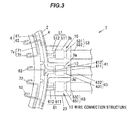
- FIG.3 is an explanatory structural diagram illustrating a wire connection structure at a power supply line-supporting portion of the electricity collection and distribution ring.
- An electricity collection and distribution ring 1 in the first embodiment is configured to, e.g., distribute a driving current to an electric motor mounted on a vehicle and to collect a current generated by the electric motor. Since this electric motor is a well-known three-phase AC motor, illustration thereof is omitted and only basic configuration will be briefly described.
- the electric motor is provided with a rotor and a stator which generates a magnetic field to rotate the rotor.
- the stator has plural teeth arranged at equal intervals in a circumferential direction about a rotational axis of the rotor.
- AC currents of three phases (U-, V- and W-phases), all 120 degrees out of phase with one another, are supplied to the stator.
- U-, V- and W-phase windings are respectively wound around three teeth which are arranged side-by-side in a circumferential direction and form one set, and plural sets of three teeth are radially arranged on the stator.
- the electricity collection and distribution ring 1 in the first embodiment shown in FIGS.1A to 2 is used for, e.g., collecting and distributing electricity from/to an electric motor having a stator on which eight sets of teeth with U-, V- and W-phase windings (eight teeth for each phase) are provided.
- the electricity collection and distribution ring 1 is provided with first to third bus rings 4 to 6 as annular power distribution members, a neutral-phase bus ring 7 and an annular holding member 2 for holding the first to third bus rings 4 to 6 and the neutral-phase bus ring 7 .
- the holding member 2 is molded into a shape adapted to hold the first to third bus rings 4 to 6 and the neutral-phase bus ring 7 . Note that, in FIG.2 , illustration of the holding member 2 is omitted to show the first to third bus rings 4 to 6 and the neutral-phase bus ring 7 which are held thereinside.
- the first bus ring 4 has a first annular wire 41 which is an insulated wire formed annularly around the rotational axis of the rotor of the electric motor, plural first connecting terminals 42 protruding radially inward from the first annular wire 41 , and a first power supply line 43 and a power supply terminal 430 for supplying power to the first annular wire 41 .
- the first annular wire 41 is composed of a metal conductor 411 formed of a highly conductive metal such as copper and an insulation 412 formed of an insulating resin covering the outer periphery of the metal conductor 411 .
- the metal conductor 411 in the first embodiment is a solid wire formed using one linear conductor having a circular cross section.
- the metal conductor 411 is partially exposed by removing the insulation 412 , and the plural first connecting terminals 42 are fixed to the exposed metal conductor 411 by crimping and are thereby electrically connected to the metal conductor 411 .
- the first power supply line 43 is composed of a twisted wire 431 as a core formed by twisting strands made of a highly conductive metal such as copper and an insulation 432 formed of an insulating resin covering the outer periphery of the twisted wire 431 .
- the second bus ring 5 and the third bus ring 6 are configured in the same manner as the first bus ring 4 . That is, the second bus ring 5 has a second annular wire 51 , plural second connecting terminals 52 protruding radially inward from the second annular wire 51 , and a second power supply line 53 and a power supply terminal 530 for supplying power to the second annular wire 51 .
- the second annular wire 51 has a metal conductor 511 formed using a solid wire and an insulation 512 covering the metal conductor 511 , and the plural second connecting terminals 52 are fixed by crimping to portions of the second annular wire 51 where the insulation 512 is removed.
- the second power supply line 53 is composed of a twisted wire 531 as a core and an insulation 532 formed of an insulating resin covering the outer periphery of the twisted wire 531 .
- the third bus ring 6 has a third annular wire 61 , plural third connecting terminals 62 protruding radially inward from the third annular wire 61 , and a third power supply line 63 and a power supply terminal 630 for supplying power to the third annular wire 61 .
- the third annular wire 61 has a metal conductor 611 formed using a solid wire and an insulation 612 covering the metal conductor 611 , and the plural third connecting terminals 62 are fixed by crimping to portions of the third annular wire 61 where the insulation 612 is removed.
- the third power supply line 63 is composed of a twisted wire 631 as a core and an insulation 632 formed of an insulating resin covering the outer periphery of the twisted wire 631 .
- the neutral-phase bus ring 7 is composed of plural arcuate conductors 7 a each having an arc shape, and is formed in an annular shape as a whole by arranging the arcuate conductors 7 a along a circumferential direction of the holding member 2 .
- the arcuate conductor 7 a is formed by plastically deforming a plate-like conductive member having a predetermined shape.
- the arcuate conductor 7 a integrally has an arc portion 71 shaped into an arc shape by bending at plural positions and neutral-phase connecting terminals 72 protruding radially inward from the arc portion 71 .
- the first to third bus rings 4 to 6 are arranged in parallel to each other along the axial direction of the electricity collection and distribution ring 1 .
- the neutral-phase bus ring 7 is arranged inside the first to third bus rings 4 to 6 in a radial direction of the electricity collection and distribution ring 1 .
- the first to third connecting terminals 42 , 52 , 62 and the neutral-phase connecting terminal 72 each have a J-shape, as viewed from the axial direction of the electricity collection and distribution ring 1 , of which curved portion formed by folding back a radially inward end portion protrudes radially inward from the inner peripheral surface of the holding member 2 .
- the first connecting terminal 42 of the first bus ring 4 is crimped and connected at a radially inward end portion to an end portion of the U-phase winding of the non-illustrated electric motor.
- the second connecting terminal 52 of the second bus ring 5 is connected to an end portion of the V-phase winding and the third connecting terminal 62 of the third bus ring 6 is connected to an end portion of the W-phase winding.
- Other end portions of the U-, V- and W-phase windings are connected to the neutral-phase connecting terminals 72 of the neutral-phase bus ring 7 .
- both end portions of the metal conductor 411 of the first annular wire 41 are connected to each other by a first wire connection member 3 a inside a power supply line-supporting portion 23 .
- both end portions of the metal conductor 511 of the second annular wire 51 are connected to each other by a second wire connection member 3 b inside the power supply line-supporting portion 23 and both end portions of the metal conductor 611 of the third annular wire 61 are connected to each other by a third wire connection member 3 c inside the power supply line-supporting portion 23 .
- the structure inside the holding member 2 formed of a molding resin is indicated by a dashed line.
- a wire connection structure 10 inside the power supply line-supporting portion 23 will be described in detail below.
- the first wire connection member 3 a, the second wire connection member 3 b and the third wire connection member 3 c are configured in the same manner and the first wire connection member 3 a will be taken as an example to explain the wire connection structure 10 in the first embodiment.
- the wire connection structure 10 is a connection structure for connecting electric wires to each other and is configured to connect the first annular wire 41 to the first power supply line 43 by the first wire connection member 3 a.
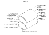
- FIG.4 is a perspective view showing the first wire connection member 3 a.
- FIG.5 is an explanatory diagram for explaining electrical connection between the first annular wire 41 and the first power supply line 43 using the first wire connection member 3 a.
- the first wire connection member 3 a connects the first annular wire 41 as a first wire to the first power supply line 43 as a second wire by crimping.
- both of end portions (tip portions 41 a and 41 b) of the first annular wire 41 formed using a solid wire are connected to a tip portion 431 a of the first power supply line 43 by the first wire connection member 3 a, which practically means that the first wire connection member 3 a connects two solid wires to one twisted wire.
- the twisted wire 431 of the first power supply line 43 is formed by helically twisting plural strands 431 b.
- a diameter of the strand 431 b is, e.g., 0.05 to 0.5 mm and multiple strands 431b (e.g., more than ten strands) are twisted together to form the twisted wire 431 .
- the first power supply line 43 has higher flexibility than the first annular wire 41 . This improves routing properties of the electricity collection and distribution ring 1.
- the first wire connection member 3 a has a partition 33 which divides a first housing space 31 a for housing the tip portions 41 a and 41 b of the first annular wire 41 from a second housing space 32 a for housing the tip portion 431 a of the first power supply line 43 , a first housing portion 31 which, together with the partition 33 , forms the first housing space 31 a, and a second housing portion 32 which, together with the partition 33 , forms the second housing space 32 a.
- the partition 33 is arranged between the first housing portion 31 and the second housing portion 32 which are arranged side-by-side in a radial direction with respect to the axial direction of the tip portions 41 a and 41 b of the first annular wire 41 and the tip portion 431 a of the first power supply line 43 . That is, the first housing portion 31 and the second housing portion 32 are arranged to be overlapped in a direction crossing a direction of inserting (housing) the first annular wire 41 and the first power supply line 43 into the first and second housing portions 31 and 32 .
- the axial direction of the first annular wire 41 is a direction of axes m 1 and m 2 (see FIG.5 ) both of which are the central axis of the metal conductor 411 formed using a solid wire the tip portions 41 a and 41 b.
- the axial direction of the first power supply line 43 is a direction of axis m 3 (see FIG.5 ) which is the central axis of the first power supply line 43 at the tip portion 431 a.
- the tip portions 41 a and 41 b of the first annular wire 41 and the tip portion 431 a of the first power supply line 43 are connected in an overlapping manner via the partition 33 as viewed from a radial direction which is orthogonal to the axes m 1 , m 2 and m 3 .
- the first housing portion 31 , the second housing portion 32 and the partition 33 of the first wire connection member 3 a are integrally formed by bending a plate-like metal member.
- a single-plate metal member having a rectangular shape is bent into an S-shape by plastic deformation, thereby forming the first wire connection member 3 a.
- the metal member can be formed of a conductive metal material such as iron or copper, or an alloy material containing such metals.
- the first housing portion 31 is constructed from a first sidewall 30 a which is curved so that the first housing space 31 a having an ellipse shape is formed between itself and the partition 33 .
- the second housing portion 32 is constructed from a second sidewall 30 b which is curved so that the second housing space 32 a having an ellipse shape is formed between itself and the partition 33 . That is, the first housing portion 31 and the second housing portion 32 are arranged adjacent to each other with a single metal plate as the partition 33 interposed therebetween.
- a portion of the first sidewall 30 a facing the partition 33 in an arrangement direction of the first housing portion 31 and the second housing portion 32 serves as a lower curved portion 310 which has a curved shape with a smaller curvature than other portion of the first sidewall 30 a.
- a portion of the second sidewall 30 b facing the partition 33 in the arrangement direction of the first housing portion 31 and the second housing portion 32 serves as an upper curved portion 320 which has a curved shape with a smaller curvature than other portion of the second sidewall 30 b.
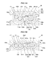
- FIGS.6A and 6B show a crimping process in which the first annular wire 41 is connected to the first power supply line 43 by crimping the first wire connection member 3 a in the arrangement direction of the first housing portion 31 and the second housing portion 32 , wherein FIG.6A shows a state before crimping and FIG.6B shows a state when the crimping is completed.
- FIGS.6A and 6B are cross sectional views showing the first wire connection member 3 a, an upper electrode 80 and a lower electrode 81 taken in line A-A in FIG.5 .
- a crimping electrode 8 shown in FIGS.6A and 6B is used and connection is carried out by fusing (heat crimping) which is solid-state welding to join solid objects to each other.
- fusing heat crimping
- compressing the first housing portion 31 and the second housing portion 32 in the arrangement direction thereof with the partition 33 interposed therebetween causes the first annular wire 41 to come into contact with the first housing portion 31 as well as the partition 33 and the power supply line 43 to come into contact with the second housing portion 32 as well as the partition 33 , thereby electrically connecting the first annular wire 41 to the power supply line 43 .
- This connection method will be described in detail below.
- the first annular wire 41 and the power supply line 43 are inserted into the first wire connection member 3 a respectively from housing directions D 1 and D 2 shown in FIG.5 .
- the housing directions D 1 and D 2 are opposite directions.
- the tip portions 41 a and 41 b of the metal conductor 411 of the first annular wire 41 are inserted into the first wire connection member 3 a from a first end face 34 a side so as to be housed in the first housing space 31 a, and the tip portion 431 a of the twisted wire 431 of the first power supply line 43 is inserted from a second end face 34 b side, which is opposite to the first end face 34 a, so as to be housed in the second housing space 32 a.
- the first wire connection member 3 a is placed on the crimping electrode 8 so that the upper electrode 80 of the crimping electrode 8 is located on the upper curved portion 320 side of the second housing portion 32 of the first wire connection member 3 a and the lower electrode 81 is located on the lower curved portion 310 side of the first housing portion 31 .
- the partition 33 and the lower curved portion 310 are positioned so that at least the center portions thereof in an arrangement direction of the tip portions 41 a and 41 b of the first annular wire 41 are orthogonal to a relative movement direction of the upper electrode 80 and the lower electrode 81 .
- an end face 80 a of the upper electrode 80 and an end face 81 a of the lower electrode 81 are brought close to each other by relatively moving the upper electrode 80 and the lower electrode 81 , and the first wire connection member 3 a is crimped by applying pressure.
- the tip portions 41 a and 41 b of the first annular wire 41 come into contact with the lower curved portion 310 and the partition 33 in the first housing portion 31 and are sandwiched therebetween.
- the tip portion 431 a of the twisted wire 431 of the first power supply line 43 comes into contact with the upper curved portion 320 and the partition 33 in the second housing portion and is sandwiched therebetween.
- an upper recessed portion 80 b to be in contact with the upper curved portion 320 is provided on the upper electrode 80 .
- the upper recessed portion 80 b is a groove formed along a direction of length L of the first wire connection member 3 a shown in FIG.5 , i.e., along an axial direction of the first wire connection member 3 a, and has an inner surface forming a substantially semi-elliptical shape as viewed from the axial direction.
- a lower recessed portion 81 b to be in contact with the lower curved portion 310 is provided on the end face 81 a of the lower electrode 81.
- the lower recessed portion 81 b is a groove formed along the direction of length L of the first wire connection member 3 a and has an inner surface forming a shape which is flat in the middle and is rounded at both ends as viewed from the axial direction.
- the middle portion is made flat since it is easy to align the tip portions 41 a and 41 b of the metal conductor 411 and a crimping force is thus evenly applied thereto.
- an electric current is supplied by a non-illustrated power unit from the upper electrode 80 to the lower electrode 81 or vice versa.
- This electric current generates Joule heat inside the metal conductor 411 of the first annular wire 41 and the twisted wire 431 of the first power supply line 43 as well as at the contact portions between the metal conductor 411 /the twisted wire 431 and the first wire connection member 3 a, and temperature of the metal conductor 411 , the twisted wire 431 and the first wire connection member 3 a thus increases. Then, the metal conductor 411 and the twisted wire 431 are welded to the first wire connection member 3 a due to the increase in temperature.
- the upper electrode 80 and the lower electrode 81 are relatively moved in a direction of separating from each other to take out the first wire connection member 3 a in which the first annular wire 41 and the first power supply line 43 are crimped.
- the first bus ring 4 in which the first annular wire 41 and the first power supply line 43 are connected by the first wire connection member 3 a is obtained.
- the second bus ring 5 and the third bus ring 6 are obtained in the same manner as the first bus ring 4 .
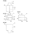
- FIG.7 is a perspective view showing a wire connection member 3 A in the second embodiment of the invention.
- FIGS.8A to 8D are projection views showing the wire connection member 3 A, wherein FIG.8A is a front view, FIG.8B is a plan view, FIG.8C is a right side view and FIG8D is a bottom view.
- FIGS.9A and 9B are schematic views showing a process of crimping the wire connection member 3 A, wherein FIG.9A shows a state before crimping and FIG.9B shows a state after crimping.
- the wire connection member 3 A in the second embodiment integrally has a partition 33 A which divides a first housing space 310 A for housing the tip portions 41 a and 41 b of the first annular wire 41 from a second housing space 320 A for housing the tip portion 431 a of the first power supply line 43 , a first housing portion 31 A which, together with the partition 33 A, forms the first housing space 310 A, and a second housing portion 32 A which, together with the partition 33 A, forms the second housing space 320 A.
- the partition 33 A is arranged between the first housing portion 31 A and the second housing portion 32 A which are arranged side-by-side in a radial direction with respect to the axial direction of the tip portions 41 a and 41 b of the first annular wire 41 and the tip portion 431 a of the first power supply line 43 .
- an inner space of a cylindrical portion 30 A formed into a cylindrical shape by bending a plate-like metal member is divided into two spaces by the partition 33 A which is a single plate, such that the one of the divided inner spaces serves as the first housing space 310 A and another as the second housing space 320 A.
- the cylindrical portion 30 A is formed in a rectangular cylindrical shape with rounded corners.
- the cylindrical portion 30 A is composed of an upper wall portion 301 A, a lower wall portion 302 A and first and second sidewall portions 303 A and 304 A.
- the upper wall portion 301 A has a slit 300 A formed in the middle between end faces of the bent plate-like metal member.
- the lower wall portion 302 A faces the upper wall portion 301 A with the partition 33 A interposed therebetween.
- the first and second sidewall portions 303 A and 304 A face each other and each couple the upper wall portion 301 A to the lower wall portion 302 A.
- the partition 33 A is coupled to and integrated with the cylindrical portion 30 A by a coupling portion 305 A which extends from the lower wall portion 302 A in a curved manner.
- the partition 33 A is formed inside the cylindrical portion 30 A so as to have a wider width than the coupling portion 305 A.
- the first housing portion 31 A has a U-shape formed by the upper wall portion 301 A and portions of the first and second sidewall portions 303 A and 304 A on the upper wall portion 301 A side with respect to the partition 33 A.
- the second housing portion 32 A has a U-shape formed by the lower wall portion 302 A and portions of the first and second sidewall portions 303 A and 304 A on the lower wall portion 302 A side with respect to the partition 33 A.
- the tip portions 41 a and 41 b of the first annular wire 41 are placed in the first housing space 310 A and the tip portion 431 a of the first power supply line 43 is placed in the second housing space 320 A, as shown in FIG.9A .
- the wire connection member 3 A is pressed by a non-illustrated upper jig coming into contact with the upper wall portion 301 A of the cylindrical portion 30 A and a non-illustrated lower jig coming into contact with the lower wall portion 302 A of the cylindrical portion 30 A, thereby compressing the first housing portion 31 A and the second housing portion 32 A with the partition 33 A interposed therebetween in an arrangement direction of the first housing portion 31 A and the second housing portion 32 A.
- the tip portions 41 a and 41 b of the first annular wire 41 come into contact with the upper wall portion 301 A and the partition 33 A and are sandwiched therebetween.
- the tip portion 431 a of the first power supply line 43 comes into contact with the lower wall portion 302 A and the partition 33 A and is sandwiched therebetween.
- the first annular wire 41 is electrically connected to the first power supply line 43 via the wire connection member 3 A.
- the tip portions 41 a and 41 b of the first annular wire 41 and the tip portion 431 a of the first power supply line 43 may be welded to the wire connection member 3 A by supplying an electric current between the upper and lower jigs in a state that the wire connection member 3 A is pressed.
- FIG.10 is a perspective view showing a configuration of a wire connection member 3 B in the third embodiment of the invention.
- the wire connection member 3 B has a partition 33 B which divides a first housing space 310 B for housing the tip portions 41 a and 41 b of the first annular wire 41 from a second housing space 320 B for housing the tip portion 431 a of the first power supply line 43 , a first housing portion 31 B which, together with the partition 33 B, forms the first housing space 310 B, and a second housing portion 32 B which, together with the partition 33 B, forms the second housing space 320 B.
- the partition 33 B is arranged between the first housing portion 31 B and the second housing portion 32 B which are arranged side-by-side in a radial direction with respect to the axial direction of the tip portions 41 a and 41 b of the first annular wire 41 and the tip portion 431 a of the first power supply line 43 .
- the wire connection member 3 B is formed by bending a material which is a plate-like metal member having a band-like shape.
- a first lower curved portion 301 B and a second lower curved portion 302 B are formed by bending both longitudinal end portions of the material in a folded-back manner and the longitudinal middle portion of the material serves as an upper wall portion 303 B which faces the first and second lower curved portions 301 B and 302 B.
- the upper wall portion 303 B has a flat-plate shape, and the first housing space 310 B of the first housing portion 31 B and the second housing space 320 B of the second housing portion 32 B are formed on a lower surface 303 Ba side of the upper wall portion 303 B.
- the end portion 301 Ba of the first lower curved portion 301 B serves as a first partition 33 Ba
- the end portion 302 Ba of the second lower curved portion 302 B serves as a second partition 33 Bb
- the partition 33 B is composed of a combination of the first partition 33 Ba and the second partition 33 Bb.
- FIGS.11A and 11B are schematic views showing a process of crimping the wire connection member 3 B, wherein FIG.11A shows a state before crimping and FIG.11B shows a state after crimping.
- the wire connection member 3 B is crimped by a crimping electrode 8 B in a state that the tip portions 41 a and 41 b of the first annular wire 41 are housed in the first housing portion 31 B and the tip portion 431 a of the first power supply line 43 is housed in the second housing portion 32 B, thereby electrically connecting the first annular wire 41 to the first power supply line 43 .
- connection is carried out by fusing (heat crimping).
- the crimping electrode 8 B is composed of an upper electrode 80 B, a first lower electrode 81 B and a second lower electrode 82 B.
- Each of the first lower electrode 81 B and the second lower electrode 82 B is independently relatively movable in an approaching/separating direction with respect to the upper electrode 80 B.
- An upper recessed portion 80 Bb having a bottom surface 80 Bc to be in contact with the upper wall portion 303 B of the wire connection member 3 B is provided on an upper end face 80 Ba of the upper electrode 80 B.
- the upper recessed portion 80 Bb is a groove formed along a direction of inserting the tip portions 41 a and 41 b of the first annular wire 41 into the first housing portion 31 B.
- the bottom surface 80 Bc located in the middle in a width direction orthogonal to an extending direction thereof is a flat surface and end portions on both sides of the bottom surface 80 Bc are curved in a rounded manner.
- the first lower electrode 81 B is provided with a lower recessed portion 81 Bb on an end face 81 Ba which faces the upper electrode 80 B.
- the lower recessed portion 81 Bb is a groove extending parallel to the upper recessed portion 80 Bb and has a semi-elliptical shape which fits to the first lower curved portion 301 B of the first housing portion 31 B.
- the second lower electrode 82 B is provided with a lower recessed portion 82 Bb on an end face 82 Ba which faces the upper electrode 80 B.
- the lower recessed portion 82 Bb is a groove extending parallel to the upper recessed portion 80 Bb and has a shape in which the widthwise middle portion is a flat surface and both end portions are curved in a rounded manner.
- the first annular wire 41 For connecting the first annular wire 41 to the power supply line 43 by crimping the wire connection member 3 B, firstly, the first annular wire 41 is inserted into the first housing portion 31 B and the power supply line 43 is inserted from the opposite side.
- the wire connection member 3 B is placed on the crimping electrode 8 B so that the upper electrode 80 B of the crimping electrode 8 B is located to face the upper wall portion 303 B of the wire connection member 3 B, the first lower electrode 81 B is located to face the first lower curved portion 301 B of the first housing portion 31 B and the second lower electrode 82 is located to face the second lower curved portion 302 B of the second housing portion 32 B.
- the compression amount of the first housing portion 31 B is not necessarily the same as that of the second housing portion 32 B and may be different.
- a crimping force acting on the first housing portion 31 B may be different from that acting on the second housing portion 32 B.
- an electric current is supplied from the upper electrode 80 B to the first and second lower electrodes 81 B, 82 B or vice versa for fusing.
- This electric current generates Joule heat inside the metal conductor 411 of the first annular wire 41 and the twisted wire 431 of the first power supply line 43 as well as at the contact portions between the metal conductor 411 /the twisted wire 431 and the wire connection member 3 B, and temperature of the metal conductor 411 , the twisted wire 431 and the wire connection member 3 B thus increases.
- the metal conductor 411 and the twisted wire 431 are respectively welded to the wire connection member 3 B due to the increase in temperature.
- the upper electrode 80 B and the first and second lower electrodes 81 B, 82 B are relatively moved in a direction of separating from each other to take out the wire connection member 3 B in which the first annular wire 41 and the first power supply line 43 are crimped.
- the same functions and effects as ( 1 ) to ( 3 ) described in the first embodiment are obtained.
- the compression amount of and crimping force acting on the first housing portion 31 B and those of the second housing portion 32 B can be separately adjusted so that the tip portions 41 a and 4 1b of the first annular wire 41 and the tip portion 431 a of the first power supply line 43 are appropriately connected. As a result, it is possible to reliably connect the first annular wire 41 to the first power supply line 43 .
- a wire connection member (first to third wire connection member 3 a to 3 c, wire connection member 3 A/ 3 B) for connecting a first wire (first to third annular wire 41 , 51 , 61 ) to a second wire (first to third power supply line 43 , 53 , 63 ) by crimping, comprising: a partition ( 33 / 33 A/ 33 B) for dividing a first housing space ( 31 a/ 310 A/ 310 B) for housing tip portions ( 41 a, 41 b) of the first wire (first to third annular wire 41 , 51 , 61 ) from a second housing space ( 32 a/ 320 A/ 320 B) for housing a tip portion ( 431 a) of the second wire (first to third power supply line 43 , 53 , 63 ); a first housing portion ( 31 / 31 A/ 31 B) which, together with the partition ( 33 / 33 A/ 33 B), forms the first housing space ( 31 a/ 310 A/ 310 B); and
- wire connection member first to third wire connection member 3 a to 3 c, wire connection member 3 A/ 3 B described in the [ 1 ] or [ 2 ], wherein the first housing portion ( 31 / 31 A/ 31 B), the second housing portion ( 32 / 32 A/ 32 B) and the partition ( 33 / 33 A/ 33 B) are formed integrally by bending a plate-like metal member.
- wire connection member first to third wire connection member 3 a to 3 c, wire connection member 3 A/ 3 B described in any of the [ 1 ] to [ 3 ], wherein the first housing portion ( 31 / 31 A/ 31 B) and the second housing portion ( 32 / 32 A/ 32 B) are arranged adjacent to each other with the partition ( 33 / 33 A/ 33 B) interposed therebetween, the partition ( 33 / 33 A/ 33 B) comprising a single metal plate.
- An annular power distribution member (first to third bus ring 4 , 5 , 6 ), comprising; an annular wire (first to third annular wire 41 , 51 , 61 ) comprising a solid wire (metal conductor 411 , 511 , 611 ) formed in an annular shape and having connecting terminals (first to third connecting terminals 42 , 52 , 62 ) fixed at a plurality of positions in the circumferential direction; a power supply line (first to third power supply line 43 , 53 , 63 ) comprising a twisted wire ( 431 , 531 , 631 ) and supplying power to the annular wire (first to third annular wire 41 , 51 , 61 ); and a wire connection member (first to third wire connection member 3 a to 3 c, wire connection member 3 A/ 3 B) connecting both end portions (tip portions 41 a, 41 b) of the annular wire (first to third annular wire 41 , 51 , 61 ) to a tip portion
- the invention can be appropriately modified and implemented without departing from the gist thereof.
- plural (two) solid wires (the tip portions 41 a and 41 b of the first annular wire 41 ) are housed in the first housing portion 31 , 31 A or 31 B in the first to third embodiments, it is not limited thereto.
- the number of solid wires housed in the first housing portion 31 , 31 A or 31 B may be one.
- the connection members 3 a to 3 c, 3 A and 3 B in the first to third embodiments are applicable not only to the electricity collection and distribution ring 1 used for collecting and distributing electricity form/to an electric motor but also to connection between wires in various applications.
Landscapes
- Engineering & Computer Science (AREA)
- Power Engineering (AREA)
- Connections Effected By Soldering, Adhesion, Or Permanent Deformation (AREA)
- Insulation, Fastening Of Motor, Generator Windings (AREA)
Applications Claiming Priority (1)
| Application Number | Priority Date | Filing Date | Title |
|---|---|---|---|
| JP2013143880A JP6024609B2 (ja) | 2013-07-09 | 2013-07-09 | 集配電リング |
Publications (1)
| Publication Number | Publication Date |
|---|---|
| EP2824765A1 true EP2824765A1 (de) | 2015-01-14 |
Family
ID=51210266
Family Applications (1)
| Application Number | Title | Priority Date | Filing Date |
|---|---|---|---|
| EP14176236.9A Withdrawn EP2824765A1 (de) | 2013-07-09 | 2014-07-09 | Drahtverbindungselement, Drahtverbindungsstruktur und ringförmiges Leistungsverteilungselement |
Country Status (3)
| Country | Link |
|---|---|
| US (1) | US9318814B2 (de) |
| EP (1) | EP2824765A1 (de) |
| JP (1) | JP6024609B2 (de) |
Cited By (5)
| Publication number | Priority date | Publication date | Assignee | Title |
|---|---|---|---|---|
| CN110912325A (zh) * | 2019-11-19 | 2020-03-24 | 珠海凯邦电机制造有限公司 | 一种电机用推合式出线夹及采用其的电器 |
| EP3716447A1 (de) * | 2019-03-25 | 2020-09-30 | Hamilton Sundstrand Corporation | Generatoren mit flachdrahtwicklungen und verfahren zur herstellung von generatoren mit flachdrahtwicklungen |
| EP3758196A1 (de) * | 2019-06-26 | 2020-12-30 | Atieva, Inc. | Verbindungsring für motorwicklung |
| CN115443583A (zh) * | 2020-04-20 | 2022-12-06 | 株式会社自动网络技术研究所 | 带端子的电线及带连接器的电线 |
| EP4383531A4 (de) * | 2021-08-06 | 2024-11-20 | Lg Innotek Co., Ltd. | Motor und steuerungsvorrichtung |
Families Citing this family (14)
| Publication number | Priority date | Publication date | Assignee | Title |
|---|---|---|---|---|
| DE112016000369T5 (de) * | 2015-03-31 | 2017-09-28 | Aisin Aw Co., Ltd. | Stator |
| KR20170067507A (ko) * | 2015-12-08 | 2017-06-16 | 현대자동차주식회사 | 구동모터의 고정자 및 그의 코일 결선 유닛 |
| DE102015226700A1 (de) * | 2015-12-23 | 2017-06-29 | Robert Bosch Gmbh | Elektrische Verbindungsanordnung zur Verbindung von elektrischen Leitern |
| US10181658B2 (en) | 2016-03-31 | 2019-01-15 | Borgwarner Inc. | Electric machine with electrical connector |
| DE102017121908B4 (de) | 2017-09-21 | 2023-12-07 | Tdk Electronics Ag | Elektrisches Bauelement mit Litzenkontakt und Verfahren zur Herstellung eines Litzenkontakts |
| DE102017121924B3 (de) * | 2017-09-21 | 2019-02-21 | Tdk Electronics Ag | Elektrisches Bauelement mit Anschlussbereich und Verfahren zur Herstellung eines Anschlussbereichs |
| JP7192788B2 (ja) * | 2017-11-27 | 2022-12-20 | 日本電産株式会社 | バスバーユニットおよびモータ |
| JP7124504B2 (ja) * | 2018-07-11 | 2022-08-24 | 中国電力株式会社 | C型スリーブ |
| US11502572B2 (en) * | 2018-10-09 | 2022-11-15 | Ford Global Technologies, Llc | Electric machine stator |
| US11411460B2 (en) * | 2019-01-08 | 2022-08-09 | Ford Global Technologies, Llc | Electric machine assembly and method to assemble |
| US11283323B2 (en) * | 2019-02-28 | 2022-03-22 | Ford Global Technologies, Llc | Self-fixturing jumper bridge for electric machine stator |
| KR102763630B1 (ko) * | 2019-08-23 | 2025-02-07 | 현대모비스 주식회사 | 일체형 구조를 갖는 차량용 구동모터의 터미널 어셈블리 및 그 제조 방법 |
| TWI699075B (zh) | 2019-10-14 | 2020-07-11 | 群光電能科技股份有限公司 | 馬達定子結線裝置 |
| CN121285909A (zh) * | 2023-09-26 | 2026-01-06 | 舍弗勒技术股份两合公司 | 电连接装置和电动驱动机器 |
Citations (6)
| Publication number | Priority date | Publication date | Assignee | Title |
|---|---|---|---|---|
| FR2029310A5 (de) * | 1969-01-24 | 1970-10-16 | Simel | |
| US3715705A (en) * | 1971-03-29 | 1973-02-06 | Thomas & Betts Corp | Multicompartment connector |
| GB2088152A (en) * | 1980-11-15 | 1982-06-03 | Minnesota Mining & Mfg | Crimp connector |
| WO1997026700A1 (en) * | 1996-01-18 | 1997-07-24 | Shibaura Engineering Works Co., Ltd. | A motor mounted in a vehicle |
| JP2011168104A (ja) | 2010-02-16 | 2011-09-01 | Sumitomo Wiring Syst Ltd | 車両用の電線 |
| WO2011108734A1 (en) * | 2010-03-03 | 2011-09-09 | Nidec Corporation | Rotor, method of manufacturing rotor, and motor |
Family Cites Families (13)
| Publication number | Priority date | Publication date | Assignee | Title |
|---|---|---|---|---|
| US2884478A (en) * | 1955-04-20 | 1959-04-28 | Fargo Mfg Co Inc | Strand connector |
| US2965699A (en) * | 1957-02-13 | 1960-12-20 | Minnesota Mining & Mfg | Shear-action wire-connector |
| US3045303A (en) * | 1959-12-22 | 1962-07-24 | American Viscose Corp | Plastic lined seals for strapping |
| US3387080A (en) * | 1966-07-25 | 1968-06-04 | Burndy Corp | Splice connector with locking insert |
| US3514528A (en) * | 1967-11-13 | 1970-05-26 | Jimmy C Ray | Insulation piercing connector for wires |
| US3767841A (en) * | 1972-07-25 | 1973-10-23 | Amp Inc | Conductor in-slot electrical connectors |
| US3916085A (en) * | 1975-01-06 | 1975-10-28 | Essex International Inc | Electrical connector |
| JPS5818458Y2 (ja) * | 1979-07-04 | 1983-04-14 | 株式会社日立製作所 | 電気機械 |
| US5151560A (en) * | 1990-12-10 | 1992-09-29 | Amp Incorporated | Grounding connector |
| US5164545A (en) * | 1990-12-10 | 1992-11-17 | Amp Incorporated | Grounding connector |
| JPH05152011A (ja) * | 1991-11-26 | 1993-06-18 | Sumitomo Wiring Syst Ltd | 圧着端子 |
| JP4914618B2 (ja) * | 2006-02-23 | 2012-04-11 | 矢崎総業株式会社 | ステータ |
| JP5077670B2 (ja) * | 2007-11-09 | 2012-11-21 | 住友電装株式会社 | 機器用コネクタ |
-
2013
- 2013-07-09 JP JP2013143880A patent/JP6024609B2/ja not_active Expired - Fee Related
-
2014
- 2014-07-08 US US14/325,566 patent/US9318814B2/en not_active Expired - Fee Related
- 2014-07-09 EP EP14176236.9A patent/EP2824765A1/de not_active Withdrawn
Patent Citations (6)
| Publication number | Priority date | Publication date | Assignee | Title |
|---|---|---|---|---|
| FR2029310A5 (de) * | 1969-01-24 | 1970-10-16 | Simel | |
| US3715705A (en) * | 1971-03-29 | 1973-02-06 | Thomas & Betts Corp | Multicompartment connector |
| GB2088152A (en) * | 1980-11-15 | 1982-06-03 | Minnesota Mining & Mfg | Crimp connector |
| WO1997026700A1 (en) * | 1996-01-18 | 1997-07-24 | Shibaura Engineering Works Co., Ltd. | A motor mounted in a vehicle |
| JP2011168104A (ja) | 2010-02-16 | 2011-09-01 | Sumitomo Wiring Syst Ltd | 車両用の電線 |
| WO2011108734A1 (en) * | 2010-03-03 | 2011-09-09 | Nidec Corporation | Rotor, method of manufacturing rotor, and motor |
Cited By (7)
| Publication number | Priority date | Publication date | Assignee | Title |
|---|---|---|---|---|
| EP3716447A1 (de) * | 2019-03-25 | 2020-09-30 | Hamilton Sundstrand Corporation | Generatoren mit flachdrahtwicklungen und verfahren zur herstellung von generatoren mit flachdrahtwicklungen |
| EP3758196A1 (de) * | 2019-06-26 | 2020-12-30 | Atieva, Inc. | Verbindungsring für motorwicklung |
| US11133719B2 (en) | 2019-06-26 | 2021-09-28 | Atieva, Inc. | Motor winding connector ring |
| CN110912325A (zh) * | 2019-11-19 | 2020-03-24 | 珠海凯邦电机制造有限公司 | 一种电机用推合式出线夹及采用其的电器 |
| CN110912325B (zh) * | 2019-11-19 | 2021-11-23 | 珠海凯邦电机制造有限公司 | 一种电机用推合式出线夹及采用其的电器 |
| CN115443583A (zh) * | 2020-04-20 | 2022-12-06 | 株式会社自动网络技术研究所 | 带端子的电线及带连接器的电线 |
| EP4383531A4 (de) * | 2021-08-06 | 2024-11-20 | Lg Innotek Co., Ltd. | Motor und steuerungsvorrichtung |
Also Published As
| Publication number | Publication date |
|---|---|
| JP2015018642A (ja) | 2015-01-29 |
| JP6024609B2 (ja) | 2016-11-16 |
| US20150017845A1 (en) | 2015-01-15 |
| US9318814B2 (en) | 2016-04-19 |
Similar Documents
| Publication | Publication Date | Title |
|---|---|---|
| US9318814B2 (en) | Wire connection member, wire connection structure and annular power distribution member | |
| US8922079B2 (en) | Electric motor and centralized power distribution member | |
| US9214843B2 (en) | Method of binding stator coils of motor | |
| US9362796B2 (en) | Electricity collection and distribution ring and electric motor | |
| CN100386948C (zh) | 旋转电机的定子用的集配电环 | |
| CN105027393B (zh) | 汇流条单元 | |
| US9225217B2 (en) | Electric power collection and distribution ring, electric motor and method of manufacturing electric motor | |
| JP5687048B2 (ja) | バスバー装置、ステータ、ブラシレスモータ及びバスバー装置の製造方法 | |
| CN104426276B (zh) | 集配电部件的保持结构、电动机以及电动机的制造方法 | |
| JP5989496B2 (ja) | 回転電機のステータ用のバスリング | |
| US9325214B2 (en) | Electric power collection and distribution ring and electric motor | |
| JP2012110188A (ja) | 中間接続部材、ステータ及びモータ | |
| CN105027392A (zh) | 汇流条单元 | |
| JP5991261B2 (ja) | 電動機の製造方法 | |
| EP3073617A1 (de) | Elektrischer sammel- und verteilring und elektromotor | |
| JP5561415B2 (ja) | 電動機及び集中配電部材 | |
| JP6011437B2 (ja) | 電動機の製造方法 | |
| EP3079233A1 (de) | Stromsammel- und -verteilerring sowie elektromotor | |
| US20150372551A1 (en) | Structure of stator | |
| WO2023054407A1 (ja) | ステータの製造方法 | |
| JP5991173B2 (ja) | 集配電リング及び電動機 | |
| EP3079232A1 (de) | Stromsammel- und -verteilerring sowie elektromotor | |
| JP4112292B2 (ja) | 固定子およびその製造方法 | |
| JP6536932B2 (ja) | 端子金具付き電線の製造方法 | |
| JP6308680B2 (ja) | バスリングの製造方法 |
Legal Events
| Date | Code | Title | Description |
|---|---|---|---|
| 17P | Request for examination filed |
Effective date: 20140709 |
|
| AK | Designated contracting states |
Kind code of ref document: A1 Designated state(s): AL AT BE BG CH CY CZ DE DK EE ES FI FR GB GR HR HU IE IS IT LI LT LU LV MC MK MT NL NO PL PT RO RS SE SI SK SM TR |
|
| AX | Request for extension of the european patent |
Extension state: BA ME |
|
| PUAI | Public reference made under article 153(3) epc to a published international application that has entered the european phase |
Free format text: ORIGINAL CODE: 0009012 |
|
| R17P | Request for examination filed (corrected) |
Effective date: 20150714 |
|
| RBV | Designated contracting states (corrected) |
Designated state(s): AL AT BE BG CH CY CZ DE DK EE ES FI FR GB GR HR HU IE IS IT LI LT LU LV MC MK MT NL NO PL PT RO RS SE SI SK SM TR |
|
| 17Q | First examination report despatched |
Effective date: 20161006 |
|
| STAA | Information on the status of an ep patent application or granted ep patent |
Free format text: STATUS: THE APPLICATION IS DEEMED TO BE WITHDRAWN |
|
| 18D | Application deemed to be withdrawn |
Effective date: 20170217 |