EP2824797A1 - Système de transmission de puissance - Google Patents
Système de transmission de puissance Download PDFInfo
- Publication number
- EP2824797A1 EP2824797A1 EP13755645.2A EP13755645A EP2824797A1 EP 2824797 A1 EP2824797 A1 EP 2824797A1 EP 13755645 A EP13755645 A EP 13755645A EP 2824797 A1 EP2824797 A1 EP 2824797A1
- Authority
- EP
- European Patent Office
- Prior art keywords
- power transmission
- voltage
- unit
- power
- output
- Prior art date
- Legal status (The legal status is an assumption and is not a legal conclusion. Google has not performed a legal analysis and makes no representation as to the accuracy of the status listed.)
- Withdrawn
Links
Images





Classifications
-
- B—PERFORMING OPERATIONS; TRANSPORTING
- B60—VEHICLES IN GENERAL
- B60L—PROPULSION OF ELECTRICALLY-PROPELLED VEHICLES; SUPPLYING ELECTRIC POWER FOR AUXILIARY EQUIPMENT OF ELECTRICALLY-PROPELLED VEHICLES; ELECTRODYNAMIC BRAKE SYSTEMS FOR VEHICLES IN GENERAL; MAGNETIC SUSPENSION OR LEVITATION FOR VEHICLES; MONITORING OPERATING VARIABLES OF ELECTRICALLY-PROPELLED VEHICLES; ELECTRIC SAFETY DEVICES FOR ELECTRICALLY-PROPELLED VEHICLES
- B60L53/00—Methods of charging batteries, specially adapted for electric vehicles; Charging stations or on-board charging equipment therefor; Exchange of energy storage elements in electric vehicles
- B60L53/10—Methods of charging batteries, specially adapted for electric vehicles; Charging stations or on-board charging equipment therefor; Exchange of energy storage elements in electric vehicles characterised by the energy transfer between the charging station and the vehicle
- B60L53/12—Inductive energy transfer
- B60L53/126—Methods for pairing a vehicle and a charging station, e.g. establishing a one-to-one relation between a wireless power transmitter and a wireless power receiver
-
- H—ELECTRICITY
- H01—ELECTRIC ELEMENTS
- H01F—MAGNETS; INDUCTANCES; TRANSFORMERS; SELECTION OF MATERIALS FOR THEIR MAGNETIC PROPERTIES
- H01F38/00—Adaptations of transformers or inductances for specific applications or functions
- H01F38/14—Inductive couplings
-
- H—ELECTRICITY
- H01—ELECTRIC ELEMENTS
- H01M—PROCESSES OR MEANS, e.g. BATTERIES, FOR THE DIRECT CONVERSION OF CHEMICAL ENERGY INTO ELECTRICAL ENERGY
- H01M10/00—Secondary cells; Manufacture thereof
- H01M10/42—Methods or arrangements for servicing or maintenance of secondary cells or secondary half-cells
- H01M10/44—Methods for charging or discharging
-
- H—ELECTRICITY
- H02—GENERATION; CONVERSION OR DISTRIBUTION OF ELECTRIC POWER
- H02J—ELECTRIC POWER NETWORKS; CIRCUIT ARRANGEMENTS OR SYSTEMS FOR SUPPLYING OR DISTRIBUTING ELECTRIC POWER; SYSTEMS FOR STORING ELECTRIC ENERGY
- H02J50/00—Circuit arrangements or systems for wireless supply or distribution of electric power
- H02J50/10—Circuit arrangements or systems for wireless supply or distribution of electric power using inductive coupling
- H02J50/12—Circuit arrangements or systems for wireless supply or distribution of electric power using inductive coupling of the resonant type
-
- H—ELECTRICITY
- H02—GENERATION; CONVERSION OR DISTRIBUTION OF ELECTRIC POWER
- H02J—ELECTRIC POWER NETWORKS; CIRCUIT ARRANGEMENTS OR SYSTEMS FOR SUPPLYING OR DISTRIBUTING ELECTRIC POWER; SYSTEMS FOR STORING ELECTRIC ENERGY
- H02J50/00—Circuit arrangements or systems for wireless supply or distribution of electric power
- H02J50/80—Circuit arrangements or systems for wireless supply or distribution of electric power involving the exchange of data, concerning supply or distribution of electric power, between transmitting devices and receiving devices
-
- H—ELECTRICITY
- H02—GENERATION; CONVERSION OR DISTRIBUTION OF ELECTRIC POWER
- H02J—ELECTRIC POWER NETWORKS; CIRCUIT ARRANGEMENTS OR SYSTEMS FOR SUPPLYING OR DISTRIBUTING ELECTRIC POWER; SYSTEMS FOR STORING ELECTRIC ENERGY
- H02J50/00—Circuit arrangements or systems for wireless supply or distribution of electric power
- H02J50/90—Circuit arrangements or systems for wireless supply or distribution of electric power involving detection or optimisation of position, e.g. alignment
-
- H—ELECTRICITY
- H02—GENERATION; CONVERSION OR DISTRIBUTION OF ELECTRIC POWER
- H02J—ELECTRIC POWER NETWORKS; CIRCUIT ARRANGEMENTS OR SYSTEMS FOR SUPPLYING OR DISTRIBUTING ELECTRIC POWER; SYSTEMS FOR STORING ELECTRIC ENERGY
- H02J7/00—Circuit arrangements for charging or discharging batteries or for supplying loads from batteries
- H02J7/40—Circuit arrangements for charging or discharging batteries or for supplying loads from batteries characterised by the exchange of charge or discharge related data
- H02J7/42—Circuit arrangements for charging or discharging batteries or for supplying loads from batteries characterised by the exchange of charge or discharge related data with electronic devices having internal batteries, e.g. mobile phones
-
- H—ELECTRICITY
- H02—GENERATION; CONVERSION OR DISTRIBUTION OF ELECTRIC POWER
- H02M—APPARATUS FOR CONVERSION BETWEEN AC AND AC, BETWEEN AC AND DC, OR BETWEEN DC AND DC, AND FOR USE WITH MAINS OR SIMILAR POWER SUPPLY SYSTEMS; CONVERSION OF DC OR AC INPUT POWER INTO SURGE OUTPUT POWER; CONTROL OR REGULATION THEREOF
- H02M7/00—Conversion of AC power input into DC power output; Conversion of DC power input into AC power output
- H02M7/42—Conversion of DC power input into AC power output without possibility of reversal
- H02M7/44—Conversion of DC power input into AC power output without possibility of reversal by static converters
- H02M7/48—Conversion of DC power input into AC power output without possibility of reversal by static converters using discharge tubes with control electrode or semiconductor devices with control electrode
- H02M7/53—Conversion of DC power input into AC power output without possibility of reversal by static converters using discharge tubes with control electrode or semiconductor devices with control electrode using devices of a triode or transistor type requiring continuous application of a control signal
- H02M7/537—Conversion of DC power input into AC power output without possibility of reversal by static converters using discharge tubes with control electrode or semiconductor devices with control electrode using devices of a triode or transistor type requiring continuous application of a control signal using semiconductor devices only, e.g. single switched pulse inverters
- H02M7/5387—Conversion of DC power input into AC power output without possibility of reversal by static converters using discharge tubes with control electrode or semiconductor devices with control electrode using devices of a triode or transistor type requiring continuous application of a control signal using semiconductor devices only, e.g. single switched pulse inverters in a bridge configuration
-
- B—PERFORMING OPERATIONS; TRANSPORTING
- B60—VEHICLES IN GENERAL
- B60L—PROPULSION OF ELECTRICALLY-PROPELLED VEHICLES; SUPPLYING ELECTRIC POWER FOR AUXILIARY EQUIPMENT OF ELECTRICALLY-PROPELLED VEHICLES; ELECTRODYNAMIC BRAKE SYSTEMS FOR VEHICLES IN GENERAL; MAGNETIC SUSPENSION OR LEVITATION FOR VEHICLES; MONITORING OPERATING VARIABLES OF ELECTRICALLY-PROPELLED VEHICLES; ELECTRIC SAFETY DEVICES FOR ELECTRICALLY-PROPELLED VEHICLES
- B60L2210/00—Converter types
- B60L2210/20—AC to AC converters
-
- B—PERFORMING OPERATIONS; TRANSPORTING
- B60—VEHICLES IN GENERAL
- B60L—PROPULSION OF ELECTRICALLY-PROPELLED VEHICLES; SUPPLYING ELECTRIC POWER FOR AUXILIARY EQUIPMENT OF ELECTRICALLY-PROPELLED VEHICLES; ELECTRODYNAMIC BRAKE SYSTEMS FOR VEHICLES IN GENERAL; MAGNETIC SUSPENSION OR LEVITATION FOR VEHICLES; MONITORING OPERATING VARIABLES OF ELECTRICALLY-PROPELLED VEHICLES; ELECTRIC SAFETY DEVICES FOR ELECTRICALLY-PROPELLED VEHICLES
- B60L2210/00—Converter types
- B60L2210/30—AC to DC converters
-
- H—ELECTRICITY
- H01—ELECTRIC ELEMENTS
- H01M—PROCESSES OR MEANS, e.g. BATTERIES, FOR THE DIRECT CONVERSION OF CHEMICAL ENERGY INTO ELECTRICAL ENERGY
- H01M10/00—Secondary cells; Manufacture thereof
- H01M10/42—Methods or arrangements for servicing or maintenance of secondary cells or secondary half-cells
- H01M10/46—Accumulators structurally combined with charging apparatus
-
- H—ELECTRICITY
- H01—ELECTRIC ELEMENTS
- H01M—PROCESSES OR MEANS, e.g. BATTERIES, FOR THE DIRECT CONVERSION OF CHEMICAL ENERGY INTO ELECTRICAL ENERGY
- H01M2220/00—Batteries for particular applications
- H01M2220/20—Batteries in motive systems, e.g. vehicle, ship, plane
-
- H—ELECTRICITY
- H01—ELECTRIC ELEMENTS
- H01M—PROCESSES OR MEANS, e.g. BATTERIES, FOR THE DIRECT CONVERSION OF CHEMICAL ENERGY INTO ELECTRICAL ENERGY
- H01M8/00—Fuel cells; Manufacture thereof
- H01M8/04—Auxiliary arrangements, e.g. for control of pressure or for circulation of fluids
- H01M8/04298—Processes for controlling fuel cells or fuel cell systems
- H01M8/04313—Processes for controlling fuel cells or fuel cell systems characterised by the detection or assessment of variables; characterised by the detection or assessment of failure or abnormal function
- H01M8/04664—Failure or abnormal function
- H01M8/04671—Failure or abnormal function of the individual fuel cell
-
- Y—GENERAL TAGGING OF NEW TECHNOLOGICAL DEVELOPMENTS; GENERAL TAGGING OF CROSS-SECTIONAL TECHNOLOGIES SPANNING OVER SEVERAL SECTIONS OF THE IPC; TECHNICAL SUBJECTS COVERED BY FORMER USPC CROSS-REFERENCE ART COLLECTIONS [XRACs] AND DIGESTS
- Y02—TECHNOLOGIES OR APPLICATIONS FOR MITIGATION OR ADAPTATION AGAINST CLIMATE CHANGE
- Y02E—REDUCTION OF GREENHOUSE GAS [GHG] EMISSIONS, RELATED TO ENERGY GENERATION, TRANSMISSION OR DISTRIBUTION
- Y02E60/00—Enabling technologies; Technologies with a potential or indirect contribution to GHG emissions mitigation
- Y02E60/10—Energy storage using batteries
-
- Y—GENERAL TAGGING OF NEW TECHNOLOGICAL DEVELOPMENTS; GENERAL TAGGING OF CROSS-SECTIONAL TECHNOLOGIES SPANNING OVER SEVERAL SECTIONS OF THE IPC; TECHNICAL SUBJECTS COVERED BY FORMER USPC CROSS-REFERENCE ART COLLECTIONS [XRACs] AND DIGESTS
- Y02—TECHNOLOGIES OR APPLICATIONS FOR MITIGATION OR ADAPTATION AGAINST CLIMATE CHANGE
- Y02E—REDUCTION OF GREENHOUSE GAS [GHG] EMISSIONS, RELATED TO ENERGY GENERATION, TRANSMISSION OR DISTRIBUTION
- Y02E60/00—Enabling technologies; Technologies with a potential or indirect contribution to GHG emissions mitigation
- Y02E60/30—Hydrogen technology
- Y02E60/50—Fuel cells
-
- Y—GENERAL TAGGING OF NEW TECHNOLOGICAL DEVELOPMENTS; GENERAL TAGGING OF CROSS-SECTIONAL TECHNOLOGIES SPANNING OVER SEVERAL SECTIONS OF THE IPC; TECHNICAL SUBJECTS COVERED BY FORMER USPC CROSS-REFERENCE ART COLLECTIONS [XRACs] AND DIGESTS
- Y02—TECHNOLOGIES OR APPLICATIONS FOR MITIGATION OR ADAPTATION AGAINST CLIMATE CHANGE
- Y02T—CLIMATE CHANGE MITIGATION TECHNOLOGIES RELATED TO TRANSPORTATION
- Y02T10/00—Road transport of goods or passengers
- Y02T10/60—Other road transportation technologies with climate change mitigation effect
- Y02T10/70—Energy storage systems for electromobility, e.g. batteries
-
- Y—GENERAL TAGGING OF NEW TECHNOLOGICAL DEVELOPMENTS; GENERAL TAGGING OF CROSS-SECTIONAL TECHNOLOGIES SPANNING OVER SEVERAL SECTIONS OF THE IPC; TECHNICAL SUBJECTS COVERED BY FORMER USPC CROSS-REFERENCE ART COLLECTIONS [XRACs] AND DIGESTS
- Y02—TECHNOLOGIES OR APPLICATIONS FOR MITIGATION OR ADAPTATION AGAINST CLIMATE CHANGE
- Y02T—CLIMATE CHANGE MITIGATION TECHNOLOGIES RELATED TO TRANSPORTATION
- Y02T10/00—Road transport of goods or passengers
- Y02T10/60—Other road transportation technologies with climate change mitigation effect
- Y02T10/7072—Electromobility specific charging systems or methods for batteries, ultracapacitors, supercapacitors or double-layer capacitors
-
- Y—GENERAL TAGGING OF NEW TECHNOLOGICAL DEVELOPMENTS; GENERAL TAGGING OF CROSS-SECTIONAL TECHNOLOGIES SPANNING OVER SEVERAL SECTIONS OF THE IPC; TECHNICAL SUBJECTS COVERED BY FORMER USPC CROSS-REFERENCE ART COLLECTIONS [XRACs] AND DIGESTS
- Y02—TECHNOLOGIES OR APPLICATIONS FOR MITIGATION OR ADAPTATION AGAINST CLIMATE CHANGE
- Y02T—CLIMATE CHANGE MITIGATION TECHNOLOGIES RELATED TO TRANSPORTATION
- Y02T90/00—Enabling technologies or technologies with a potential or indirect contribution to GHG emissions mitigation
- Y02T90/10—Technologies relating to charging of electric vehicles
- Y02T90/12—Electric charging stations
-
- Y—GENERAL TAGGING OF NEW TECHNOLOGICAL DEVELOPMENTS; GENERAL TAGGING OF CROSS-SECTIONAL TECHNOLOGIES SPANNING OVER SEVERAL SECTIONS OF THE IPC; TECHNICAL SUBJECTS COVERED BY FORMER USPC CROSS-REFERENCE ART COLLECTIONS [XRACs] AND DIGESTS
- Y02—TECHNOLOGIES OR APPLICATIONS FOR MITIGATION OR ADAPTATION AGAINST CLIMATE CHANGE
- Y02T—CLIMATE CHANGE MITIGATION TECHNOLOGIES RELATED TO TRANSPORTATION
- Y02T90/00—Enabling technologies or technologies with a potential or indirect contribution to GHG emissions mitigation
- Y02T90/10—Technologies relating to charging of electric vehicles
- Y02T90/14—Plug-in electric vehicles
Definitions
- the present invention relates to a wireless electric power transmission system that uses a magnetic resonance antenna of a magnetic resonance method.
- Patent Document 1 Japanese PCT National Publication No. 2009-501510
- a resonance frequency of a power transmission antenna is equal to a resonance frequency of a power receiving antenna. Therefore, from the power transmission antenna to the power receiving antenna, energy can be efficiently transmitted.
- the power transmission distance can be from several tens of centimeters to several meters.
- Patent Document 2 JP2010-68657A ) is: a wireless electric power transmission device, which includes AC power output means for outputting AC power of a predetermined frequency, a first resonance coil, and a second resonance coil that is disposed in such a way as to face the first resonance coil and in which AC power output from the AC power output means is output to the first resonance coil and the AC power is transmitted to the second resonance coil in a non-contact manner through resonance phenomena, is characterized by including frequency setting means for measuring a resonance frequency of the first resonance coil and a resonance frequency of the second resonance coil and setting the frequency of the AC power output from the AC power output means to an intermediate frequency of the resonance frequencies.
- the inventors found, through experiments, that, if a positional change occurs between the power transmission antenna and the power receiving antenna in the above wireless electric power transmission system of the magnetic resonance method, there is an optimum one corresponding to the positional change as a load condition when the power receiving system is viewed totally.
- the invention disclosed in the above Patent Document 2 carries out the transmission of electric power without taking into account the load condition. Therefore, the problem is that the overall electric power transmission efficiency decreases.
- an electric power transmission system which transmits electric energy via an electromagnetic field from a power transmission antenna to a power receiving antenna, is characterized by including: an inverter unit that converts DC voltage to AC voltage of a predetermined frequency to output; a power transmission-side control unit that controls a drive frequency of the inverter unit and a voltage value of DC voltage input to the inverter unit, and controls power output from the inverter unit; the power transmission antenna to which AC voltage is input from the inverter unit; a rectifying unit that rectifies an output of the power receiving antenna to obtain DC voltage, and outputs the DC voltage; a step-up and step-down unit that steps up or down DC voltage output from the rectifying unit to output; a battery that is charged with an output of the step-up and step-down unit; and a power receiving-side control unit that controls the step-up and step-down unit in such a way as to charge the battery with maximum efficiency.
- the electric power transmission system of claim 1 is characterized in that: the power transmission-side control unit controls in such a way as to keep an output power value of the inverter unit at a constant level; and the power receiving-side control unit controls the step-up and step-down unit in such a way as to charge the battery with a maximum power value.
- the electric power transmission system of claim 1 or 2 is characterized in that, as the drive frequency of the inverter unit, a higher extreme-value frequency is used out of two extreme-value frequencies.
- the power transmission system is so controlled as to output a constant level of electric power
- the power receiving system is so controlled as to receive electric power as maximum electric power.
- FIG. 1 is a block diagram of an electric power transmission system according to an embodiment of the present invention.
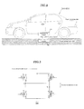
- FIG. 2 is a schematic diagram showing an example in which an electric power transmission system 100 of the embodiment of the present invention is mounted on a vehicle.
- the electric power transmission system 100 of the present invention is suitably used in a system that charges vehicle-mounted batteries, such as those of an electric vehicle (EV) or a hybrid electric vehicle (HEV), for example.
- a power receiving antenna 210 is placed to make it possible to receive electric power.
- the electric power transmission system 100 of the present embodiment electric power is transmitted to the above vehicle in a non-contact manner.
- the power transmission system 100 is therefore provided in a parking space where the vehicle can be stopped.
- a parking space which is a vehicle-charging space
- a power transmission antenna 140 and other components of the electric power transmission system 100 of the present embodiment are buried under the ground.
- a user of the vehicle parks the vehicle in the parking space in which the electric power transmission system of the present embodiment is provided. Electric energy is transmitted from the power transmission antenna 140 to the power receiving antenna 210, which is mounted on the vehicle, via electromagnetic fields.
- the electric power transmission system 100 of the present embodiment is used as described above. Therefore, the positional relationship between the power transmission antenna 140 and the power receiving antenna 210 changes each time the vehicle is parked in the parking space, and a frequency that gives an optimum electric power transmission efficiency would change accordingly. Therefore, after the vehicle is parked, or after the positional relationship between the power transmission antenna 140 and the power receiving antenna 210 is fixed, an optimum frequency is determined based on the relationship between the phase of voltage input to the power transmission antenna and the phase of current before the transmission of charging power actually takes place.
- a rectifying unit 110 is a converter that converts AC voltage from commercial power supply into a constant level of DC voltage.
- the DC voltage from the rectifying unit 110 is input to a step-up and step-down unit 120.
- the step-up and step-down unit 120 steps up or down the DC voltage to a desired voltage value.
- a power transmission-side control unit 150 can control how to set the value of the voltage output from the step-up and step-down unit 120.
- An inverter unit 130 generates, from the DC voltage supplied from the step-up and step-down unit 120, a predetermined level of AC voltage to input to the power transmission antenna 140.
- FIG. 3 is a diagram showing the inverter unit of the electric power transmission system of the embodiment of the present invention. As shown in FIG. 3 , for example, the inverter unit 130 includes four field-effect transistors (FET) Q A to Q D , which are connected in full-bridge configuration.
- FET field-effect transistors
- connection portion T1 which is located between the switching elements Q A and Q B connected in series
- connection portion T2 which is located between the switching elements Q C and Q D connected in series
- the power transmission antenna 140 is connected between a connection portion T1 and T2.
- a drive signal is input from the power transmission-side control unit 150.
- the frequency for driving the inverter unit 130 can be controlled from the power transmission-side control unit 150.
- the output of the above inverter unit 130 is supplied to the power transmission antenna 140.
- the power transmission antenna 140 includes a coil having an inductance component, and resonates with the vehicle-mounted power receiving antenna 210, which is disposed in such a way as to face the power transmission antenna 140. In this manner, electric energy output from the power transmission antenna 140 can be transmitted to the power receiving antenna 210.
- impedance matching may be carried out by a matching unit, which is not shown in the diagrams.
- the matching unit may include a passive element having a predetermined circuit constant.
- a resonance frequency of the power transmission antenna 140 becomes equal to a resonance frequency of the power receiving antenna 210. Therefore, from the power transmission antenna to the power receiving antenna, energy is efficiently transmitted.
- Voltage V 1 and current I 1 which are input to the inverter unit 130, and voltage V 2 and current I 2 , which are output from the inverter unit 130, are measured by the power transmission-side control unit 150.
- the power transmission-side control unit 150 has the above configuration, and therefore can detect the phase of voltage V 2 output from the inverter unit 130 and the phase of current I 2 .
- the power transmission-side control unit 150 includes a general-purpose information processing unit, which includes a CPU, a ROM, which keeps programs that run on the CPU, a RAM, which serves as a work area for the CPU, and the like.
- the power transmission-side control unit 150 calculates a difference in phase between the detected voltage V 2 and current I 2 .
- the power transmission-side control unit 150 performs the actual transmission of charging power by controlling the voltage of the DC voltage output from the step-up and step-down unit 120 and the frequency of the AC voltage output from the inverter unit 130. During such a control process, the frequency and the like are determined by referencing a control program stored in the power transmission-side control unit 150.
- the control program is stored in a storage means, and a calculation unit of the power transmission-side control unit 150 is so configured as to be able to reference the control program.
- a communication unit 170 wirelessly communicates with a vehicle-side communication unit 270 so the transmitting and receiving of data is possible between the power transmission side and the vehicle.
- the data received by the communication unit 170 is transferred to the power transmission-side control unit 150, in which the data is processed.
- the power transmission-side control unit 150 is able to transmit predetermined information to the vehicle side via the communication unit 170.
- the power receiving antenna 210 is designed to resonate with the power transmission antenna 140 to receive electric energy output from the power transmission antenna 140.
- the AC power received by the power receiving antenna 210 is rectified by a rectifying unit 220.
- the output of the rectifying unit 220 is stepped up or down by a step-up and step-down unit 230 to a predetermined voltage value, and is accumulated in a battery 240.
- the step-up and step-down unit 230 controls a process of charging the battery 240 on the basis of a command from a power receiving-side control unit 250.
- Voltage V 3 and current I 3 which are input to the battery 240 from the step-up and step-down unit 230, are measured by the power receiving-side control unit 250. Based on the measured voltage V 3 and current I 3 , the power receiving-side control unit 250 controls the step-up and step-down unit 230, and thereby controls the process of charging the battery 240 in such a way as to follow an appropriate charging profile of the battery 240.
- the step-up and step-down unit 230 includes a current sensor and a voltage sensor; the step-up and step-down unit 230 can select one of charging modes, i.e., a constant current charging mode, a constant power charging mode, or a constant voltage charging mode, to charge the battery 240 by conducting feedback control of an output voltage. As described later, in the constant current charging mode, power maximization control of charging power for the battery 240 can be performed.
- the power receiving-side control unit 250 includes a general-purpose information processing unit, which includes a CPU, a ROM, which keeps programs that run on the CPU, a RAM, which serves as a work area for the CPU, and the like.
- the power receiving-side control unit 250 works cooperatively with each of components connected to the power receiving-side control unit 250 shown in the diagrams.
- FIG. 4 is a diagram showing a charging profile 260 of the battery 240.
- the charging profile 260 is one example of charging profiles for the battery 240. In charging the battery 240, other profiles may be used.
- the charging profile shown in FIG. 4 is used when the amount of electricity stored in the battery 240 is almost zero.
- constant output charging CP control
- P const constant level of power
- CV control constant voltage charging
- the communication unit 270 wirelessly communicates with the communication unit 170 of the vehicle charging equipment side so the transmitting and receiving of data is possible between the power transmission-side system and the vehicle-side system.
- the data received by the communication unit 270 is transferred to the power receiving-side control unit 250, in which the data is processed.
- the power receiving-side control unit 250 is able to transmit predetermined information to the power transmission side via the communication unit 270.
- the power receiving-side control unit 250 is able to transmit, to the vehicle charging equipment-side system, information about which charging mode, i.e., a constant power (CP) charging mode or a constant voltage (CV) charging mode, is being used to charge the battery 240.
- CP constant power
- CV constant voltage
- the inventors found, through experiments, that, if a positional change occurs between the power transmission antenna 140 and the power receiving antenna 210 in the magnetic resonance-type wireless electric power transmission system of the present invention, there is an optimum one corresponding to the positional change as a load condition when the power receiving system is viewed totally.
- FIG. 5 is results of experiments showing that the relationship between load conditions and overall efficiency changes according to a positional change between the power transmission antenna 140 and the power receiving antenna 210.
- FIG. 6 is a diagram illustrating definitions of positional relationship between the power transmission antenna 140 and the power receiving antenna 210.
- Both the power transmission antenna 140 and the power receiving antenna 210 are a substantially rectangular coil that is wound in a spiral shape. Under restriction, which means the power receiving antenna 210 is mounted on the vehicle, the relative position of the power transmission antenna 140 to the power receiving antenna 210 where a coupling coefficient between the power transmission antenna 140 and the power receiving antenna 210 is maximized is defined as an optimum relative position. In this case, a positional change between the power transmission antenna 140 and the power receiving antenna 210 can be defined as a deviation from the optimum relative position. As the positional change between the antennas relative to the optimum relative position becomes larger, the coupling coefficient becomes smaller.
- FIG. 5 shows results of experiments on the relationship between load conditions and overall efficiency when a longitudinal-direction positional change between the power transmission antenna 140 and the power receiving antenna 210, which are substantially rectangular coils, is varied.
- a load is represented by Z in the case of FIG. 1 .
- efficiency is represented by ⁇ in the case of FIG. 1 .
- the load conditions that yield the most efficient outcome vary according to the positional relationship between the power transmission antenna 140 and the power receiving antenna 210.
- the load conditions vary according to the voltage of the battery 240 of the power transmission-side system.
- the power transmission-side system is controlled in such a way as to output a constant level of electric power; the power receiving-side system is controlled in such a way as to receive electric power as maximum electric power.
- the transmission of electric power is possible under optimum load conditions that vary according to the positional change between the power receiving antenna and the power transmission antenna.
- the following describes the flow of a control process of the inverter unit 130 in the electric power transmission system 100 having the above configuration.
- the power transmission-side system carries out control in such a way as to keep a constant level of output from the inverter unit 130 as well as to track the frequency.
- the power receiving-side system carries out control in such a way as to maximize the electric power to be received, thereby making possible the transmission of electric power under optimum load conditions that vary according to the positional change between the power receiving antenna and the power transmission antenna.
- the electric power transmission system of the present invention is not limited to the above-described control operations.
- a command may be issued to the control unit of the power transmission-side system and the control unit of the power receiving-side system in such a way as to apply a comprehensively optimum solution to the entire system, so that the transmission of electric power is carried out under optimum load conditions that vary according to the positional change between the power receiving antenna and the power transmission antenna.
- FIG. 7 is a diagram showing a flowchart of a control process in the power transmission-side system of the electric power transmission system according to the embodiment of the present invention.
- step S100 the process starts.
- step S101 voltage V 2 is set to initial voltage V start .
- step S105 a determination is made as to whether or not the transmission of electric power ends.
- the process proceeds to step S06.
- the determination result is YES, the process proceeds to step S108 and ends.
- step S106 a determination is made as to whether or not the output power W has reached target output power W target .
- the process proceeds to step S102.
- the determination result is NO, the voltage V 2 is stepped up or down, or adjusted, at step S107.
- the following describes power maximization control by the power receiving-side system for the above power transmission-side system.
- the algorithm in order to receive maximized power, the algorithm is so designed that the step-up and step-down unit 230 is optimally operated to charge the battery, or the load of the power receiving side, with maximum efficiency.
- the step-up and step-down unit 230 is controlled in such a way that the power that charges the battery 240 is maximized. Therefore, the flowchart shown in FIG. 8 is one example of such control. Since the step-up and step-down unit 230 is connected to the battery 240, the voltage V 3 measured by the power receiving-side control unit 250 is determined based on the state of the battery 240.
- the step-up and step-down operation of the step-up and step-down unit 230 is not observed as a change in the voltage V 3 in a short time-frame, but is observed as current I 3 .
- a change in the voltage V 3 occurs over the entire charging time. Therefore, it is desirable that W 3 , which is the product of those values, should be observed.
- FIG. 8 is a diagram showing a flowchart of a control process in the power receiving-side system of the electric power transmission system according to the embodiment of the present invention.
- step S203 the step-up operation of the step-up and step-down unit 230 is carried out.
- step S204 current value I 3 and voltage value V 3 are obtained.
- the step-up operation is an operation in which the step-up and step-down unit 230 can increase the output voltage V 3 if the battery 240 is not connected.
- step S206 a determination is made as to whether or not the output power has increased.
- the determination result is YES
- the process goes back to step S203.
- the determination result is NO
- the process proceeds to step S207.
- a current step-up setting value is set in the step-up and step-down unit 230 as a value for giving maximum output.
- step S208 a determination is made as to whether or not the output power has increased during the operation through S206.
- the process proceeds to step S209.
- the determination result is NO, the process proceeds to step S214 and ends.
- the step-down operation is an operation in which the step-up and step-down unit 230 can decrease the output voltage V 3 if the battery 240 is not connected.
- step S212 a determination is made as to whether or not the output power has increased.
- the process goes back to step S209.
- the determination result is NO
- step S213 a current step-down setting value is set in the step-up and step-down unit 230 as a value for giving maximum output.
- step S214 ends.
- the step-up setting value and the step-down setting value are exclusively adopted. After the step-down setting value is set, the step-up setting value, which is set at step S207, is not used.
- the power transmission-side system is controlled in such a way as to output a constant level of electric power
- the power receiving-side system is controlled in such a way as to receive electric power as maximum electric power.
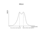
- Frequencies that give extreme values of transmission efficiency in the wireless electric power transmission system will be described. During the power transmission of the system, there might be two frequencies that give extreme values of transmission efficiency. The following describes how to select an optimal one for the system out of the two frequencies.
- FIG. 9 is a diagram showing an example of frequency dependence of transmission efficiency when the power transmission antenna 140 and the power receiving antenna 210 are placed close to each other.
- FIG. 10 is a schematic diagram showing the state of current and electric fields at a first extreme-value frequency.
- the phase of current flowing through a coil of the power transmission antenna 140 is substantially equal to the phase of current flowing through a coil of the power receiving antenna 210.
- the vectors of magnetic fields are aligned at around a middle point of the coil of the power transmission antenna 140 and of the coil of the power receiving antenna 210.
- This state is regarded as generating a magnetic wall whose magnetic field is perpendicular to a symmetry plane located between the power transmission antenna 140 and the power receiving antenna 210.
- FIG. 11 is a schematic diagram showing the state of current and electric fields at a second extreme-value frequency.
- the phase of current flowing through the coil of the power transmission antenna 140 is substantially opposite to the phase of current flowing through the coil of the power receiving antenna 210.
- the vectors of magnetic fields are aligned at around the symmetry plane of the coil of the power transmission antenna 140 and of the coil of the power receiving antenna 210. This state is regarded as generating an electric wall whose magnetic field is horizontal to the symmetry plane located between the power transmission antenna 140 and the power receiving antenna 210.
- an extreme-value frequency at which an electric wall is generated at a symmetry plane between the power transmission antenna 140 and the power receiving antenna 210 is selected when there are two frequencies, i.e., the first and second extreme-value frequencies, as frequencies giving extreme-values.
- FIG. 12 is a diagram showing characteristics at an extreme-value frequency (first frequency) at which a magnetic wall emerges, among the extreme-value frequencies that give two extreme values.
- FIG. 12 (A) is a diagram showing how voltage (V 1 ) and current (I 1 ) vary at the power transmission side when a change or variation of the load of the battery 240 (load) occurs.
- FIG. 12 (B) is a diagram showing how voltage (V 3 ) and current (I 3 ) vary at the power receiving side when a change or variation of the load of the battery 240 (load) occurs. According to the characteristics shown in FIG. 12 , as the load of the battery 240 (load) at the power receiving side increases, the voltage rises.
- the power receiving antenna 210 seems like a constant current source.
- the power receiving antenna 210 works like a constant current source, if an emergency stop occurs due to trouble of the battery 240 or the like at the load side when the transmission of power is performed, the voltages of both end portions of the power receiving antenna 210 will rise.
- FIG. 13 is a diagram showing characteristics at an extreme-value frequency (second frequency) at which an electric wall emerges, among the extreme-value frequencies that give two extreme values.
- FIG. 13(A) is a diagram showing how voltage (V 1 ) and current (I 1 ) vary at the power transmission side when a change or variation of the load of the battery 240 (load) occurs.
- FIG. 13(B) is a diagram showing how voltage (V 3 ) and current (I 3 ) vary at the power receiving side when a change or variation of the load of the battery 240 (load) occurs. According to the characteristics shown in FIG. 13 , as the load of the battery 240 (load) at the power receiving side increases, the current decreases.
- the power receiving antenna 210 seems like a constant voltage source.
- the voltages of both end portions of the power receiving antenna 210 will not rise. Therefore, in the electric power transmission system of the present invention, the voltage does not rise to a high level when the load plunges; the transmission of electric power can be performed in a stable manner.
- the charging circuit seems like a current source.
- the charging circuit seems like a voltage source.
- the characteristics of FIG. 13 are more preferred for the battery 240 (load) because the current decreases. Therefore, according to the present embodiment, when there are two frequencies, i.e., the first and second extreme-value frequencies, an extreme-value frequency at which an electric wall emerges at the symmetry plane between the power transmission antenna 140 and the power receiving antenna 210 is selected.
- the above electric power transmission system of the present invention can quickly determine an optimum frequency for the transmission of electric power, and therefore can perform the transmission of electric power efficiently and in a short time.
- the charging circuit seems like a voltage source. Therefore, the advantage is that, as the output to the battery 240 changes due to charging control, the output of the inverter unit 130 rises or falls accordingly, and therefore it is easy to handle. Moreover, when an emergency shutdown of the power receiving-side control unit 250 occurs, the power to be supplied is automatically minimized. Therefore, there is no need for additional equipment.
- the rectifying unit 220 seems like a voltage source. Therefore, the advantage is that, as the output to the battery 240 changes due to charging control, the output of the step-up and step-down unit 120 rises or falls accordingly, and therefore it is easy to handle.
- the frequency control method of the inverter unit of the electric power transmission system of the present invention is available for both the case where an extreme-value frequency at which an electric wall emerges at the symmetry plane between the power transmission antenna 140 and the power receiving antenna 210 for two extreme values is selected and the case where an extreme-value frequency at which a magnetic wall emerges is selected. Furthermore, the frequency control method may be effectively available for the case where only one extreme value exists at around a resonance point.
- the electric power transmission system of the present invention is suitably used in a magnetic resonance-type wireless electric power transmission system that charges vehicles, such as electric vehicles (EV) or hybrid electric vehicles (HEV), which have rapidly become popular in recent years.
- vehicles such as electric vehicles (EV) or hybrid electric vehicles (HEV)
- EV electric vehicles
- HEV hybrid electric vehicles
- the transmission of electric power be carried out by taking into account a load condition when the power receiving-side system is viewed totally.
- such an operation was not carried out in the past, and the problem was that the overall power transmission efficiency decreased.
Landscapes
- Engineering & Computer Science (AREA)
- Power Engineering (AREA)
- Computer Networks & Wireless Communication (AREA)
- Manufacturing & Machinery (AREA)
- Chemical & Material Sciences (AREA)
- Chemical Kinetics & Catalysis (AREA)
- Electrochemistry (AREA)
- General Chemical & Material Sciences (AREA)
- Transportation (AREA)
- Mechanical Engineering (AREA)
- Charge And Discharge Circuits For Batteries Or The Like (AREA)
- Secondary Cells (AREA)
- Electric Propulsion And Braking For Vehicles (AREA)
Applications Claiming Priority (2)
| Application Number | Priority Date | Filing Date | Title |
|---|---|---|---|
| JP2012044374A JP2013183496A (ja) | 2012-02-29 | 2012-02-29 | 電力伝送システム |
| PCT/JP2013/055077 WO2013129451A1 (fr) | 2012-02-29 | 2013-02-27 | Système de transmission de puissance |
Publications (2)
| Publication Number | Publication Date |
|---|---|
| EP2824797A1 true EP2824797A1 (fr) | 2015-01-14 |
| EP2824797A4 EP2824797A4 (fr) | 2015-11-04 |
Family
ID=49082646
Family Applications (1)
| Application Number | Title | Priority Date | Filing Date |
|---|---|---|---|
| EP13755645.2A Withdrawn EP2824797A4 (fr) | 2012-02-29 | 2013-02-27 | Système de transmission de puissance |
Country Status (5)
| Country | Link |
|---|---|
| US (1) | US20150054456A1 (fr) |
| EP (1) | EP2824797A4 (fr) |
| JP (1) | JP2013183496A (fr) |
| CN (1) | CN104160589A (fr) |
| WO (1) | WO2013129451A1 (fr) |
Cited By (6)
| Publication number | Priority date | Publication date | Assignee | Title |
|---|---|---|---|---|
| WO2017211557A1 (fr) * | 2016-06-07 | 2017-12-14 | Robert Bosch Gmbh | Système de transmission pour transmettre d'énergie sans contact |
| EP3229343A4 (fr) * | 2015-02-06 | 2018-05-02 | IHI Corporation | Système d'alimentation électrique sans contact |
| EP3462564A4 (fr) * | 2017-04-07 | 2019-05-08 | Guangdong Oppo Mobile Telecommunications Corp., Ltd. | Système, appareil et procédé de charge sans fil, et dispositif à charger |
| FR3081266A1 (fr) * | 2018-05-16 | 2019-11-22 | Renault S.A.S | Systeme et procede de transfert de puissance electrique sans contact entre un dispositif fixe au sol et un vehicule |
| US11075542B2 (en) | 2017-04-07 | 2021-07-27 | Guangdong Oppo Mobile Telecommunications Corp., Ltd. | Device to-be-charged, wireless charging apparatus, and wireless charging method |
| US11394250B2 (en) | 2017-04-07 | 2022-07-19 | Guangdong Oppo Mobile Telecommunications Corp., Ltd. | Wireless charging device, wireless charging method and device to be charged |
Families Citing this family (19)
| Publication number | Priority date | Publication date | Assignee | Title |
|---|---|---|---|---|
| KR101697418B1 (ko) | 2012-05-09 | 2017-01-17 | 도요타지도샤가부시키가이샤 | 차량 |
| DE112012006861B4 (de) * | 2012-08-31 | 2024-01-11 | Siemens Aktiengesellschaft | Batterieladesystem und Verfahren zum kabellosen Laden einer Batterie |
| JP6200167B2 (ja) * | 2013-02-27 | 2017-09-20 | デクセリアルズ株式会社 | 受電装置、受電電力調整方法、受電電力調整プログラム、及び半導体装置 |
| JP6206579B2 (ja) | 2014-03-18 | 2017-10-04 | 株式会社Ihi | 給電装置及び非接触給電システム |
| JP2015220933A (ja) * | 2014-05-20 | 2015-12-07 | 株式会社テクノバ | 非接触給電システム |
| KR102332172B1 (ko) * | 2014-09-26 | 2021-11-29 | 삼성전자주식회사 | 무선 전력 송신기 및 무선 전력 수신기 |
| KR20170141254A (ko) * | 2015-05-04 | 2017-12-22 | 마포스 쏘시에타 페르 아지오니 | 인식 시스템을 포함하는 측정 조립체 및 인식 방법 |
| JP5995022B1 (ja) | 2015-09-10 | 2016-09-21 | パナソニックIpマネジメント株式会社 | 無線電力伝送システムおよび送電装置 |
| KR20180101822A (ko) * | 2017-03-06 | 2018-09-14 | 쓰리엠 이노베이티브 프로퍼티즈 컴파니 | 부스트 컨버터와 송전 코일 구조체를 구비한 무선 충전 시스템 |
| US11128175B2 (en) * | 2017-09-14 | 2021-09-21 | Sharp Kabushiki Kaisha | Wireless power transmission apparatus |
| JP6962272B2 (ja) * | 2018-05-18 | 2021-11-05 | トヨタ自動車株式会社 | 非接触送電装置及び電力伝送システム |
| JP6969494B2 (ja) * | 2018-05-18 | 2021-11-24 | トヨタ自動車株式会社 | 非接触送電装置及び電力伝送システム |
| CN111566889B (zh) * | 2018-05-25 | 2024-02-02 | Oppo广东移动通信有限公司 | 无线充电接收装置及移动终端 |
| US11005298B2 (en) * | 2018-08-29 | 2021-05-11 | Integrated Device Technology, Inc. | Wireless power maximum efficiency tracking by system control |
| WO2020202422A1 (fr) * | 2019-04-01 | 2020-10-08 | 三菱電機株式会社 | Système d'alimentation électrique sans fil et dispositif de réception de puissance |
| JP2021002984A (ja) | 2019-06-25 | 2021-01-07 | Tdk株式会社 | ワイヤレス送電装置、及びワイヤレス電力伝送システム |
| CN112448054B (zh) * | 2019-08-30 | 2023-02-17 | 北京小米移动软件有限公司 | 移动终端的充电方法、装置、终端及存储介质 |
| KR102605630B1 (ko) * | 2021-05-31 | 2023-11-24 | (주) 세노텍 | 동적 코일보상 기능을 가지는 무선충전장치 및 이를 이용한 무선충전방법 |
| US20240146105A1 (en) * | 2022-10-28 | 2024-05-02 | Tracy Burnside | Wireless Electric Cord |
Family Cites Families (19)
| Publication number | Priority date | Publication date | Assignee | Title |
|---|---|---|---|---|
| KR101118710B1 (ko) | 2005-07-12 | 2012-03-13 | 메사추세츠 인스티튜트 오브 테크놀로지 | 무선 비-방사성 에너지 전달 |
| US8491159B2 (en) * | 2006-03-28 | 2013-07-23 | Wireless Environment, Llc | Wireless emergency lighting system |
| US7812481B2 (en) * | 2007-06-29 | 2010-10-12 | Seiko Epson Corporation | Power transmission control device, power transmission device, electronic instrument, and non-contact power transmission system |
| US7915858B2 (en) * | 2007-10-30 | 2011-03-29 | City University Of Hong Kong | Localized charging, load identification and bi-directional communication methods for a planar inductive battery charging system |
| US8729734B2 (en) * | 2007-11-16 | 2014-05-20 | Qualcomm Incorporated | Wireless power bridge |
| CN103259344B (zh) * | 2007-12-21 | 2016-08-10 | 捷通国际有限公司 | 用于感应功率传输的电路 |
| JP5288958B2 (ja) | 2008-09-11 | 2013-09-11 | 矢崎総業株式会社 | ワイヤレス電力送信装置及び共鳴周波数調整方法 |
| US8922066B2 (en) * | 2008-09-27 | 2014-12-30 | Witricity Corporation | Wireless energy transfer with multi resonator arrays for vehicle applications |
| US9065423B2 (en) * | 2008-09-27 | 2015-06-23 | Witricity Corporation | Wireless energy distribution system |
| JP5369693B2 (ja) * | 2009-01-15 | 2013-12-18 | 日産自動車株式会社 | 非接触給電装置 |
| JP5417942B2 (ja) * | 2009-03-31 | 2014-02-19 | 富士通株式会社 | 送電装置、送受電装置および送電方法 |
| US8390249B2 (en) * | 2009-11-30 | 2013-03-05 | Broadcom Corporation | Battery with integrated wireless power receiver and/or RFID |
| GB2488086B (en) * | 2010-01-05 | 2014-11-05 | Access Business Group Int Llc | Inductive charging system for electric vehicle |
| JP5016069B2 (ja) * | 2010-01-12 | 2012-09-05 | トヨタ自動車株式会社 | 電力伝送システムおよび車両用給電装置 |
| US9184633B2 (en) * | 2011-02-03 | 2015-11-10 | Denso Corporation | Non-contact power supply control device, non-contact power supply system, and non-contact power charge system |
| JP2013017254A (ja) * | 2011-06-30 | 2013-01-24 | Equos Research Co Ltd | 電力伝送システム |
| JP2013078171A (ja) * | 2011-09-29 | 2013-04-25 | Semiconductor Energy Lab Co Ltd | 受電装置及び非接触給電システム |
| HK1203108A1 (en) * | 2012-02-09 | 2015-10-16 | 株式会社泰库诺瓦 | Bidirectional contactless power supply system |
| JP2013183497A (ja) * | 2012-02-29 | 2013-09-12 | Equos Research Co Ltd | 電力伝送システム |
-
2012
- 2012-02-29 JP JP2012044374A patent/JP2013183496A/ja active Pending
-
2013
- 2013-02-27 EP EP13755645.2A patent/EP2824797A4/fr not_active Withdrawn
- 2013-02-27 US US14/381,793 patent/US20150054456A1/en not_active Abandoned
- 2013-02-27 CN CN201380011188.3A patent/CN104160589A/zh active Pending
- 2013-02-27 WO PCT/JP2013/055077 patent/WO2013129451A1/fr not_active Ceased
Cited By (18)
| Publication number | Priority date | Publication date | Assignee | Title |
|---|---|---|---|---|
| US10454314B2 (en) | 2015-02-06 | 2019-10-22 | Ihi Corporation | Wireless power-supplying system |
| EP3229343A4 (fr) * | 2015-02-06 | 2018-05-02 | IHI Corporation | Système d'alimentation électrique sans contact |
| EP3540912A1 (fr) * | 2015-02-06 | 2019-09-18 | IHI Corporation | Système d'alimentation sans fil |
| WO2017211557A1 (fr) * | 2016-06-07 | 2017-12-14 | Robert Bosch Gmbh | Système de transmission pour transmettre d'énergie sans contact |
| US10804752B2 (en) | 2016-06-07 | 2020-10-13 | Robert Bosch Gmbh | Transmission system for contactlessly transmitting energy |
| US10998751B2 (en) | 2017-04-07 | 2021-05-04 | Guangdong Oppo Mobile Telecommunications Corp., Ltd. | Wireless charging system, wireless charging device, wireless charging method, and device to be charged |
| CN110121824A (zh) * | 2017-04-07 | 2019-08-13 | Oppo广东移动通信有限公司 | 无线充电系统、方法及待充电设备 |
| EP3462564A4 (fr) * | 2017-04-07 | 2019-05-08 | Guangdong Oppo Mobile Telecommunications Corp., Ltd. | Système, appareil et procédé de charge sans fil, et dispositif à charger |
| US11075542B2 (en) | 2017-04-07 | 2021-07-27 | Guangdong Oppo Mobile Telecommunications Corp., Ltd. | Device to-be-charged, wireless charging apparatus, and wireless charging method |
| US11201509B2 (en) | 2017-04-07 | 2021-12-14 | Guangdong Oppo Mobile Telecommunications Corp., Ltd. | Wireless charging device, wireless charging method, and device to-be-charged |
| US11233423B2 (en) | 2017-04-07 | 2022-01-25 | Guangdong Oppo Mobile Telecommunications Corp., Ltd. | Device to-be-charged, wireless charging apparatus, and wireless charging method |
| US11355963B2 (en) | 2017-04-07 | 2022-06-07 | Guangdong Oppo Mobile Telecommunications Corp., Ltd. | Device to-be-charged, wireless charging apparatus, and wireless charging method |
| US11368050B2 (en) | 2017-04-07 | 2022-06-21 | Guangdong Oppo Mobile Telecommunications Corp., Ltd. | Wireless charging device, method, and device to-be-charged |
| US11394250B2 (en) | 2017-04-07 | 2022-07-19 | Guangdong Oppo Mobile Telecommunications Corp., Ltd. | Wireless charging device, wireless charging method and device to be charged |
| US11437865B2 (en) | 2017-04-07 | 2022-09-06 | Guangdong Oppo Mobile Telecommunications Corp., Ltd. | Wireless charging system, wireless charging method, and device to-be-charged |
| US11437848B2 (en) | 2017-04-07 | 2022-09-06 | Guangdong Oppo Mobile Telecommunications Corp., Ltd. | Wireless charging device, device to-be-charged, and method for controlling charging |
| CN110121824B (zh) * | 2017-04-07 | 2024-01-02 | Oppo广东移动通信有限公司 | 无线充电系统、方法及待充电设备 |
| FR3081266A1 (fr) * | 2018-05-16 | 2019-11-22 | Renault S.A.S | Systeme et procede de transfert de puissance electrique sans contact entre un dispositif fixe au sol et un vehicule |
Also Published As
| Publication number | Publication date |
|---|---|
| CN104160589A (zh) | 2014-11-19 |
| JP2013183496A (ja) | 2013-09-12 |
| EP2824797A4 (fr) | 2015-11-04 |
| WO2013129451A1 (fr) | 2013-09-06 |
| US20150054456A1 (en) | 2015-02-26 |
Similar Documents
| Publication | Publication Date | Title |
|---|---|---|
| EP2824797A1 (fr) | Système de transmission de puissance | |
| US9270138B2 (en) | Electric power transmission system | |
| EP2833509A1 (fr) | Système de transmission électrique | |
| JP5988191B2 (ja) | 電力伝送システム | |
| KR101318848B1 (ko) | 비접촉 급전 설비, 차량 및 비접촉 급전 시스템의 제어 방법 | |
| US9067497B2 (en) | Power transmitting device and power transfer system | |
| US10886786B2 (en) | Multi-mode wireless power receiver control | |
| US20140103711A1 (en) | Contactless power receiving device, vehicle equipped with the same, contactless power transmitting device, and contactless power transfer system | |
| WO2013002319A1 (fr) | Système de transmission de courant électrique | |
| EP2693600A1 (fr) | Système de transmission de puissance | |
| EP2866328B1 (fr) | Dispositif de transmission électrique sans contact | |
| KR20140025529A (ko) | 비접촉 급전 장치 | |
| CN104105616A (zh) | 车辆用受电装置、供电设备以及电力传输系统 | |
| EP3026786B1 (fr) | Système pour transmission de puissance électrique | |
| JP2013158188A (ja) | 電力伝送システム | |
| JP2013126307A (ja) | 電力伝送システム | |
| JP2013212033A (ja) | 電力伝送システム | |
| JP2013132141A (ja) | 電力伝送システム | |
| JP2012110211A (ja) | 電力伝送システム | |
| JP2013212034A (ja) | 電力伝送システム | |
| JP2012210116A (ja) | 電力伝送システム | |
| JP2014197935A (ja) | 電力伝送システム |
Legal Events
| Date | Code | Title | Description |
|---|---|---|---|
| PUAI | Public reference made under article 153(3) epc to a published international application that has entered the european phase |
Free format text: ORIGINAL CODE: 0009012 |
|
| 17P | Request for examination filed |
Effective date: 20140828 |
|
| AK | Designated contracting states |
Kind code of ref document: A1 Designated state(s): AL AT BE BG CH CY CZ DE DK EE ES FI FR GB GR HR HU IE IS IT LI LT LU LV MC MK MT NL NO PL PT RO RS SE SI SK SM TR |
|
| AX | Request for extension of the european patent |
Extension state: BA ME |
|
| DAX | Request for extension of the european patent (deleted) | ||
| RA4 | Supplementary search report drawn up and despatched (corrected) |
Effective date: 20151002 |
|
| RIC1 | Information provided on ipc code assigned before grant |
Ipc: H01M 10/46 20060101ALI20150928BHEP Ipc: H02J 7/02 20060101ALI20150928BHEP Ipc: H01M 10/44 20060101ALI20150928BHEP Ipc: B60L 11/18 20060101ALI20150928BHEP Ipc: H02J 5/00 20060101ALI20150928BHEP Ipc: H02J 17/00 20060101AFI20150928BHEP Ipc: H02J 7/00 20060101ALI20150928BHEP |
|
| STAA | Information on the status of an ep patent application or granted ep patent |
Free format text: STATUS: THE APPLICATION HAS BEEN WITHDRAWN |
|
| 18W | Application withdrawn |
Effective date: 20160502 |