EP2824800A1 - Rotorkörper mit Dauermagneten, und elektrisch umlaufende Maschine, die einen solchen Körper umfasst - Google Patents
Rotorkörper mit Dauermagneten, und elektrisch umlaufende Maschine, die einen solchen Körper umfasst Download PDFInfo
- Publication number
- EP2824800A1 EP2824800A1 EP20140175499 EP14175499A EP2824800A1 EP 2824800 A1 EP2824800 A1 EP 2824800A1 EP 20140175499 EP20140175499 EP 20140175499 EP 14175499 A EP14175499 A EP 14175499A EP 2824800 A1 EP2824800 A1 EP 2824800A1
- Authority
- EP
- European Patent Office
- Prior art keywords
- flange
- rotor body
- magnets
- hub
- arms
- Prior art date
- Legal status (The legal status is an assumption and is not a legal conclusion. Google has not performed a legal analysis and makes no representation as to the accuracy of the status listed.)
- Withdrawn
Links
Images
Classifications
-
- H—ELECTRICITY
- H02—GENERATION; CONVERSION OR DISTRIBUTION OF ELECTRIC POWER
- H02K—DYNAMO-ELECTRIC MACHINES
- H02K1/00—Details of the magnetic circuit
- H02K1/06—Details of the magnetic circuit characterised by the shape, form or construction
- H02K1/22—Rotating parts of the magnetic circuit
- H02K1/27—Rotor cores with permanent magnets
- H02K1/2706—Inner rotors
- H02K1/272—Inner rotors the magnetisation axis of the magnets being perpendicular to the rotor axis
- H02K1/274—Inner rotors the magnetisation axis of the magnets being perpendicular to the rotor axis the rotor consisting of two or more circumferentially positioned magnets
- H02K1/2753—Inner rotors the magnetisation axis of the magnets being perpendicular to the rotor axis the rotor consisting of two or more circumferentially positioned magnets the rotor consisting of magnets or groups of magnets arranged with alternating polarity
- H02K1/276—Magnets embedded in the magnetic core, e.g. interior permanent magnets [IPM]
- H02K1/2766—Magnets embedded in the magnetic core, e.g. interior permanent magnets [IPM] having a flux concentration effect
- H02K1/2773—Magnets embedded in the magnetic core, e.g. interior permanent magnets [IPM] having a flux concentration effect consisting of tangentially magnetized radial magnets
-
- H—ELECTRICITY
- H02—GENERATION; CONVERSION OR DISTRIBUTION OF ELECTRIC POWER
- H02K—DYNAMO-ELECTRIC MACHINES
- H02K1/00—Details of the magnetic circuit
- H02K1/06—Details of the magnetic circuit characterised by the shape, form or construction
- H02K1/22—Rotating parts of the magnetic circuit
- H02K1/28—Means for mounting or fastening rotating magnetic parts on to, or to, the rotor structures
Definitions
- the present invention relates to a rotor body with permanent magnets and a rotating electrical machine, including an alternator and / or an electric motor for a motor vehicle, comprising such a body.
- a rotating electrical machine - such as an alternator, a reversible alternator called an alternator / starter or an electric motor - comprises a stator surrounding a rotor having a body, such as a bundle of plates, integral with a rotor shaft.
- the stator comprises a body, such as a bundle of sheets, carrying a coil extending on either side of the stator body.
- the stator winding may comprise a plurality of windings mounted in a star or in a triangle for forming a polyphase winding, for example of the three-phase, pentaphase or hexaphase type.
- a DC rectifier rectifier bridge for example a diode bridge for forming an alternator, or an inverter, for example a transistor bridge of the Mosfet type for forming an alternator or an electric motor, is associated with windings of the stator winding.
- An air gap is present between the inner periphery of the stator body and the outer periphery of the rotor laminations.
- Such an electric machine is described for example in the document WO 02/054566 which will be referred to for more details.
- the machine is internally ventilated and the rotor shaft is driven by the engine of the motor vehicle via a motion transmission device comprising at least one belt.
- the electric machine may be reversible and constitute an alternator-starter operating in alternator mode when the rotor shaft is driving and in electric motor mode to rotate the rotor shaft.
- the rotor has a salient pole rotor body carrying coils and permanent magnets.
- the rotor shaft carries a collector with electrically conductive rings for powering the coils. In addition it is expected brooms to rub on the slip rings for electrically feeding them.
- the magnets are buried axially in the bundle of laminations of the rotor body being axially oriented relative to the axis of axial symmetry of the rotor shaft.
- the body of the rotor has a magnetic part in the form of a pack of sheets interposed between a first flange and a second flange.
- the magnetic part is carried by a central core constituted by the inner periphery of the magnetic part pierced centrally for its connection in rotation to the knurled rotor shaft for its press fit into the central core.
- the present invention aims to meet these wishes.
- One of the aims of the invention is to reduce the costs of the rotating electrical machine without reducing the performance thereof.
- the usual copper winding of the rotor of the prior art is eliminated. as well as the slip rings and the brushes which makes it possible to reduce the axial dimensions as well as the number of parts and the mass of copper.
- the performance of the electrical machine is not reduced because the number of permanent magnets is increased because they are implanted in the radial housings of the magnetic part.
- the magnets may therefore be shorter than the axial distance separating the second flange from the first shoulder after mounting the fasteners.
- the second flange is of simple shape and constitutes a pressure flange, which makes it possible to obtain a good tightening of the magnetic part between the second flange and the first shoulder. It will be noted that the magnets are formed because they are subjected to the action of elastic means with axial action.
- the number of parts is also reduced because the solution according to the invention uses two flanges due to the lack of winding at the rotor.
- the solution according to the invention is simple and economical and makes it possible to create a rotor body manipulable and transportable.
- a rotating electrical machine such as an alternator, a starter-alternator or an electric motor vehicle motor is characterized in that it comprises such a rotor body.
- the solution according to the invention is simple and economical in particular because it uses arms creating less material drop than rings. It makes it possible to create a rotor body that can be handled and transported.
- the rotor body 11 for a rotating electrical machine is, for cost and axial size reductions, without winding and thus with slip rings and brushes, which also makes it possible to reduce the number of parts and to simplify the rotor body.
- This body has permanent magnets.
- the body 11 has centrally an axis of axial symmetry X ( Figures 2 , 6 ). Directions circumferential, radial, transverse and axial will be made with respect to this axis X, which constitutes the axis of rotation of the not shown rotor shaft.
- magnetic material is meant a material capable of transmitting a magnetic flux, such as ferromagnetic material, for example a pack of sheets.
- This body 11 has two flanges 13, 14, a magnetic portion interposed between the two flanges 13, 14 and a central support core of the magnetic part.
- the magnetic part comprises radial housings for permanent magnets, in particular ferrites.
- the magnetic part may be annular and consist of a packet of sheets.
- the magnetic part may comprise a plurality of arm-shaped segments.
- the soul can belong to the magnetic part by constituting the continuous inner periphery thereof.
- the core is constituted by a hub 12, preferably of non-magnetic or slightly magnetic material, carrying the magnetic part.
- One of the flanges may be configured to be rotatably connected to a rotor shaft as described for example in the document FR 2,830,589 , which will be referred to for further details.
- This document describes a rotating electrical machine implanted between the crankshaft of the engine of the motor vehicle and the input shaft of the gearbox thereof.
- the rotor of this electric machine is integral in rotation with a rotor shaft constituting an intermediate shaft carrying in front a friction disk belonging to a first clutch, whose reaction plate is integral with the crankshaft of the engine of the engine. motor vehicle.
- this shaft is configured to be rotatably connected to the reaction plate of a second clutch, whose friction disk is integral in rotation of the input shaft of the gearbox.
- a bearing is inserted radially between the outer periphery of the rear end of the intermediate shaft and the inner periphery of a flange interposed between the first clutch and the rotor of the electric machine.
- the flange belongs to a housing interposed between the crankcase of the engine of the vehicle and the bell of the gearbox.
- This housing partially carries the stator of the electric machine.
- the flange has at its inner periphery an inclined annular internal portion carrying at its free end a bearing surface, such as a bearing.
- the intermediate shaft passes through the disengagement device of the first clutch.
- This device is in one embodiment a self-centering stop with hydraulic control.
- the disengaging device is a self-centering cable-operated stop. The stop is housed inside the inner portion of the flange.
- the rotor comprises a pack of plates carried by a hub integral with the first flange constituting the reaction plate of the second clutch.
- This first flange in the light of this document, may include an inner flange for its connection in rotation to a flange that has the intermediate rotor shaft.
- the rotor body may be rotatably connected to the rotor shaft via its central core belonging to the magnetic part as described in the document. WO 02/054566 supra.
- the rotor body may be rotatably connected to the rotor shaft via its hub constituting the central core of the rotor body.
- the rotor shaft can be knurled for its press fitting into the central bore of the core.
- the rotor shaft may be non-magnetic or slightly magnetic material.
- the outer periphery of the magnetic portion 102 defines the gap with the inner periphery of the stator body of the rotating electrical machine.
- the invention takes advantage of the second flange, which may be less thick than the first flange and the central core.
- This second flange is configured to catch the axial manufacturing tolerances of the magnets and spare them by the presence of elastic means axial action carried by the second flange.
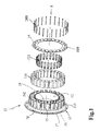
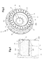
- the magnetic part of the body 11 is in this segmented embodiment and has a plurality of radial arms 102 of magnetic material.
- the arms 102 are in the circumferentially distributed figures in a regular manner being separated from each other by slots. They each consist of a plurality of elementary sheet metal arms stacked on each other for reduction of eddy current. These sheets are ferromagnetic material with possibly a coating. The sheets have a small thickness for example of 0.3 to 0.35 mm. This arrangement reduces material falls and is economical.
- the outer periphery of the arms 102 delimits the gap with the inner periphery of the stator body of the rotating electrical machine.
- the annular sector-shaped arms 102 are each provided at their outer periphery with circumferential extensions 105 extending on either side of each arm 102.
- the extensions 105 limit the magnetic leakage between two adjacent arms, an existing set between the extensions 105 directed towards one another, two adjacent arms 102.
- the body 11 of the rotor is open at its outer periphery and the slots between two adjacent arms have a reduced width at the outer periphery of the arms at level of extensions 105.
- Radially below the extensions 105 the lateral faces 112 screwed opposite two radial arms 105 are in these parallel embodiments (see the figures).
- the slots are closed internally by a central hub 12 of non-magnetic material, such as stainless steel or aluminum.
- the rotor shaft (not visible in the figures) penetrates inside the hub 12.
- the faces 112 facing two adjacent arms 102 delimit with the flanges 105 facing each other and the hub 12 of the housings 113 (see in particular FIG. figures 1 and 6 ) with parallel side faces 112 for mounting permanent magnets 114, which are ferrite in the embodiments.
- These magnets 114 are resistant to centrifugal force and are economical. Magnets here have a generally parallelepipedic shape.
- the section of the magnets 114 is in an embodiment of rectangular shape. In the embodiments the edges of the magnets 114 are rounded, alternatively chamfered so that they are generally rectangular in shape.
- the radial height of the magnets 114 is in these embodiments less than their axial length.
- the housings 113 are of radial orientation.
- the magnets 114 each have two lateral faces defining a North pole and a South pole.
- the two faces 112 thereof are opposite one pole of the two magnets flanking said arm. It is thus formed in a circumferential and alternating manner North magnetic arms and South magnetic arms. This results in a high number of North and South poles in a reduced axial size.
- the number of magnets 114 and arms is here 24. This number depends on the applications.
- the number of arms 102, housings 113 and magnets 114 is equal to at least 10.
- the blind housings 113 are delimited internally by the outer periphery of the hub 12.
- the arms 102 have holes 109 for the passage of fasteners 209, which may be magnetic or non-magnetic material.
- the organs 209 may be metallic and may consist of screws, such as tie rods, studs or bolts. In the embodiments described, the members 209 consist of rivets.
- the body 11 also has a first support flange 13 carrying the hub 12 and a first shoulder 15 for the arms 102.
- a second flange 14 of non-magnetic material such as stainless steel.
- the second flange 14 is a pressure flange of simple shape mounted on the free end of the hub 12 extending axially cantilever relative to the first flange 13, which is a support flange.
- the second flange 14 is of annular shape whose internal bore is a function of the outer diameter of the hub 12 for its assembly by axial threading on the free end of the hub 12.
- Holes are provided in the shoulder 15, carried by the first flange 13, and in the second flange 14. These holes are aligned with the holes 109 of the arms 102 as best seen in the figures 1 , 5 and 8 . They allow the passage of the fasteners 209 and a reliable clamping of the arms 102 between the shoulder 15 and the second flange 14.
- the holes are located near the outer periphery of the arms 102.
- the holes are smooth because the fasteners 209 are rivets whose heads bear against the outer face of the second flange facing away from the arms. It is the same when the members 209 are bolts.
- the holes of the shoulder 15 are threaded when the fasteners consist of screws.
- the shoulder 15 and the flanges 13, 14 are generally of transverse orientation, while the central hub 12 is of axial orientation.
- the second flange 14 is annular.
- the shoulder 15 may belong to the first flange 13, which will then non-magnetic material such as stainless steel or aluminum or cast iron.
- the shoulder 15 may belong to the hub 12 advantageously nonmagnetic material.
- the hub 12 may be in one piece with the first flange 13 then of non-magnetic material, for example by molding.
- the hub 12 and the first flange may be aluminum, aluminum alloy or cast iron. This arrangement reduces the weight of the machine because the hub and the first flange are less dense material than that of the magnetic part here fragmented arm 102.
- the hub 12 may be attached to the first flange 13, for example by welding including the laser type.
- the first flange may be magnetic material and the hub nonmagnetic material. They may each be made of steel having different magnetic properties. All combinations are therefore possible knowing that the shoulder 15 must be non-magnetic material. Note that the number of parts is reduced since it uses two flanges and a hub because the body 11 is devoid of winding.
- the radial heights of the shoulder 15 and the second flange 14 depend on the radial height of the arms 102 so that they bear on the shoulder 15 and the second flange 14.
- the outer diameter of the shoulder 15 here is generally equal to the external diameter of the arms 102.
- a mechanical connection 16 intervenes between the inner periphery of the arms 102 and the outer periphery of the hub 12.
- This connection may consist of a clamping of the inner periphery of the arms 102 on the outer periphery of the hub, for example by press fitting or shrinking.
- the mechanical connection 16 is in a form-fitting manner to facilitate the mounting of the arms 102 on the hub 12.
- This connection may be a splined connection.
- It may be a link of the mortise tenon type, tenons of the arms penetrating complementary manner in the grooves in the form of mortise hub 12.
- the arms may have at their inner periphery of the rectangular section of posts engaged in complementary manner in hub grooves 12.
- this connection is of the dovetail type, with generally trapezoid-shaped tangs penetrating into complementary grooves of the hub.
- the rotating electrical machine can rotate at a high rotational speed.
- Elastic means with radial action 122 are interposed between the inner periphery of the magnets 114 and the outer periphery of the hub 12.
- the elastic means 122 are mounted in the housings 113 and radially bias the magnets 114 in contact with the extensions 105. They alternate circumferentially with the mechanical connection 16, more precisely in these embodiments of the figures, with the mortises of the hub.
- the elastic means 122 can reduce the radial size of the magnets 114 and therefore the volume thereof.
- These elastic means are circumferentially less wide 113. They are advantageously non-magnetic material such as stainless steel.
- the outer periphery of the hub 12 constituting the bottom of the housings 113 may be of circular or flat shape to support the elastic means with radial action 122.
- the first flange 13 comprises at its outer periphery a flange 17 configured to be attached to one of the components of a clutch as described in the document FR 2,830,589 supra.
- the flange 17 is offset axially in the opposite direction relative to the arms 102 and to the first shoulder 15.
- This flange has holes (not referenced) for fixing it with the aid of fasteners, such as rivets, on the flange.
- one of the components of a clutch such as the reaction plate of a friction clutch whose friction disk is rotatably connected to the input shaft of the gearbox as in the document FR 2,830,589 .
- the flange 17 is connected to a guide ring of a torsion damper, the hub is rotatably connected to the input shaft of an automatic gearbox.
- the flange 17 is connected to the outer periphery of the first shoulder 15 by an annular portion 18, which in the figures is inclined.
- the first flange 13 of support is extended radially inwardly by a 19 perforated internal fixing flange for attachment to an intermediate rotor shaft visible in this document FR 2,830,589 .
- Fixing is carried out for example using rivets.
- this flange 19 has teeth for its connection in rotation by splines with the intermediate shaft.
- the flange 19 is configured to be rotatably connected to the intermediate rotor shaft.
- the body 11 is in place of that of the document FR 2,830,589 .
- the axial bulk of the rotor body is reduced as well as the axial size of the stator body and therefore the mass of the winding carried. by the stator body which reduces the cost of the rotating electrical machine.
- the stator body For the same outer diameter of the sheet package can reduce the inner diameter thereof.
- the hub 12 may be welded to the flange 13 at the portion 18.
- the hub 12 may be welded to the flange 13 at its axial end opposite its free end.
- the inner periphery of the hub 12 may be welded to the first flange 13.
- the welding may be advantageously a welding laser type, the laser can penetrate inside the hub 12 and allowing a welding by transparency.
- the hub has shoulders legs, which pass through associated openings of the first flange 13 for connection therewith by crimping, the ends of the legs being crushed.
- the hub 12 and the flange 13 may be cast iron as above.
- the first flange 13-hub 12 is first formed. Then we raise the arms 102 on this set. Next, the magnets 114 are mounted, then the elastic means 122. Lastly, the second flange 14 is threaded onto the free end of the hub 12 while locking the assembly with the aid of the fasteners 209.
- the assembly is simple.
- flexible plates 119 such as thin plastic plates, may be inserted between the inner periphery of the circumferential flanges 105 and the outer periphery of the magnets 114.
- the plates 119 are more flexible than the magnets 114 and may be glued on the outer periphery of the magnets. 114 to further increase flexibility.
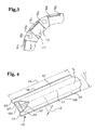
- the elastic means with radial action consist of springs 122 of curved shape or with at least one fold for local contact with the magnets 114.
- the springs 122 have in this embodiment folds for local contact with the outer periphery of the hub 12 and the inner periphery of the magnets 114. These springs are advantageously non-magnetic material, such as stainless steel, to reduce or eliminate magnetic leakage.
- the springs 122 each have a linear contact C1 with one of the hub elements 12-magnet 114 against which is supported the spring 122 and two linear contacts C2, C3 with the other element against which is supported the spring 122 .
- springs 122 each comprise a central rounded portion and two rounded end portions 126 located on either side of the central portion 125.
- the rounded central portion 125 and the rounded end portions 126 have inverted curvatures.
- Each of the springs 122 further has a beveled end 127 in a longitudinal direction, here axial,
- the bevelled end 127 has a slot 129 to reduce the rigidity of the beveled end 127 directed towards the shoulder 15. This end 127 facilitates assembly by axial threading of the springs between the magnets 114 and the hub 12
- the central portion 125 is in contact with the inner periphery of the magnet 114.
- the axial length L3 of the springs 122 is a function of the axial length between the shoulder 15 and the second flange 14 once mounted.
- the radial height between the magnet 114 and the hub 12 is less than the radial height L2 of the spring 122 in the free state.
- the circumferential width L1 of each spring 122 is less than the circumferential length between the two parallel faces 112 of the housings 113. L1 is in this example greater than L2 and less than L3.
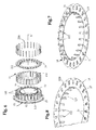
- the second flange 14 carries elastic means with axial action 21 for action on the magnets 114.
- These elastic means with axial action 21 consist in this embodiment in elastic tabs 21 cut in the second flange 14 for axial support on the magnets 114, more precisely on the axial end of the magnets 114 adjacent to the second flange 14, which may be stainless steel.
- These lugs 21 are bulged for local support on the magnets 114.
- the lugs 21 have a crease for local support on the magnets 114.
- the cutting of the tabs 21 reveals closed windows (Not referenced) generally of rectangular shape located in the vicinity of the outer periphery of the second flange 14.
- the tabs 21 each have a rooting zone at the upper edge of each window.
- the tabs 21 are directed radially inward towards the X axis and have a convex portion 23, alternatively a fold, for local support on the magnets 114 in the aforementioned manner.
- These lugs 21 are generally of the same circumferential width as the magnets 114. They are configured so as not to interfere with the arms 102.
- the convex portion 23 extends between the rooting zone of a lug 21 and the free end of it.
- the convex portion 23 or the fold extends in axial projection with respect to the rear face of the second flange facing the arms 102.
- the radial lugs 21 are compressed axially after the second flange 14 is fastened by means of the fasteners 209. Thus, they exert via their part 23 an elastic axial action on the magnets 114 resting on the shoulder 15 constituting a shoulder of reaction, the tabs 21 being pressure tabs.
- the second flange makes it possible to clamp the arms 102 and the magnets 114 independently, the axial length of the magnets 114 being generally less than that of the arms 102.
- the tabs 21 make it possible to catch the manufacturing tolerances of the magnets 114, whose manufacturing tolerances are thus less precise.
- the wafers 119 are therefore optional.
- the elastic means with axial action 122 may be thinner than the second flange 14.
- These elastic means with radial action consist of tabs 222 coming from the inner periphery of the second flange 14 by cutting and folding.
- These tongues 22 are of axial orientation. They are configured for local support on the magnets 114 and are circumferentially narrower than the magnets 114 so as not to interfere with the arms 102. These tongues 222 thus constitute springs with radial action.
- the radial height between the magnet 114 and the hub 12 is less than the radial height of the tongues 222 in the free state.
- the tongues 222 are obtained by cutting and axial folding from the central portion of the second flange 14 of annular shape.
- this central portion constitutes in the previous embodiments a drop of material.
- tabs 222 are derived from this drop of material.
- the solution is therefore economical and takes advantage of the second flange 14 to achieve another additional function to further reduce the number of parts.
- the wafers 119 are therefore optional.
- the axial length of the tongues 222 is a function of the diameter of the internal bore of the second flange 14.
- the tabs 222 are shorter axially than the magnets 114.
- Their axial length is in this embodiment less than the axial distance between the first shoulder 15 and the second flange 14.
- the elastic means with radial action are therefore shorter axially than those of the other embodiments, which makes it possible to reduce the costs and the material consumption.
- Manufacturing tolerances may be greater.
- the magnetic part consists of a pack of sheets so that this magnetic part is continuous at its outer periphery.
- the radial housings 113 blind may be devoid of slots on their outer periphery.
- the housings 113 may be provided with slits of reduced width at their outer periphery with extension presence 105 as in the first and second embodiments.
- the central core may be constituted by the inner periphery of the magnetic part.
- advantageously holes may be present at the inner periphery of the magnetic part to reduce magnetic leakage. These holes may be implanted circumferentially between two magnets and / or radially below the magnets.
- the housings 113 may therefore be delimited internally by the outer periphery of the central core and externally by the outer periphery of the magnetic portion interposed between the first and the second flange.
- the package of sheets may consist of an assembly that can be handled and transported by means of additional fasteners, preferably of non-magnetic material, passing through additional aligned holes made in the sheet package.
- the first flange 13 with internal rim 19 may be retained.
- the first flange 13 has no internal rim, the rotor shaft advantageously knurled, being forced into the internal bore of the central core of the rotor body.
- This first flange may be devoid in this case of external flange as in the document WO 02/054566 supra.
- the elastic means with radial action 21 are preserved as well as the elastic means with radial action, such as the springs 122 or the tongues 222, implanted between the central core and the inner periphery of the magnets 114.
- the package of sheets is tight. axially between the first shoulder and the second flange, the holes 109 and the fasteners 209 being retained.
- the radius of the outer periphery of the arms 102 is not constant for reducing magnetic noise and vibrations. In a variant, the radius of the outer periphery of the arms 102 is constant, as is the gap between the stator and the rotor of the rotating electrical machine. This is applicable to the third embodiment.
- the extensions 105 constitute shoulders for holding the magnets 114 and delimit the reduced width of the staggered slots in circumferential width.
- the first flange 13-hub assembly 12 has a flange 17 offset axially, which constitutes a protective collar of the gap between the rotor and the stator of the rotating electrical machine. This collar prevents dirt or other dirt from polluting the air gap.
- the outer periphery of the first flange 13 is not offset axially with respect to the running portion of the first flange 13 which is thus of transverse orientation.
- the first flange has no internal rim, the rotor shaft, advantageously knurled, being forced into the internal bore of the central core such as the hub 12.
- This first flange may be devoid in this case of outer collar as in the document WO 02/054566 supra.
- the internal bore of the central core such that the hub 12 is frustoconical in shape and the rotor shaft has a complementary frustoconical shape.
- This rotor shaft may be non-magnetic or slightly magnetic material.
- the sheet package may consist of a set that can be handled and transported by means of additional fasteners, preferably of non-magnetic material, passing through additional aligned holes made in the sheet package.
- the elastic means with axial action are attached to the second flange 14. They consist, for example, of a corrugated washer fixed on the second flange 14.
- the magnets belong to a magnetic assembly comprising a magnet and at least a portion of non-magnetic material fixed, for example by gluing, on the inner periphery of the magnet and reduced radial height.
- the elastic means with radial action act on the non-magnetic portion.
- the magnets 114 belong to a magnetic assembly comprising two magnets bonded together. These magnets may not be of the same nature, one being for example ferrite and the other in rare earth. Of course, all combinations are possible.
- the magnetic assembly may comprise at least one ferrite magnet, another magnet and at least a portion of non-magnetic material.
- the magnets are rare earth, for example neodymium-iron-boron.
- Magnetic assemblies can standardize the magnets and according to the applications and the size of the housings 113.
- a magnetic target advantageously provided with North and South poles
- a sensor holder for example Hall effect associated with the magnetic target as described in the document FR 2,745,44 to which we will refer.
- the hub 12 is attached to the first flange by a TIG type welding.
- the convex part of the tongues 222 may be in contact with the outer periphery of the hub 12 and the fold of the tongue 222 in contact with the inner periphery of the magnet 114 concerned.
- tongues 222 may have holes for example of oval shape or keystrokes to facilitate their folding.
- the legs 21 may be directed radially outwardly from the inner edge of the windows of generally rectangular shape.
- the legs 21 may include pleats for local contact with the magnets.
- One or more holes may be made in the tabs 21 or the springs 122, 222 to improve the elasticity.
- the curved shape may have a U-shaped section.
- the folds may have a V shape.
- the rotary electric machine with rotor body 11 may be equipped with a rectifier bridge of ac current in direct current partially visible in the document WO 02/054566 . It will then consist of an alternator for example of a motor vehicle.
- the rotating electric machine with rotor body 11 may be provided with an inverter as described for example in the document FR 2,745,444 .
- the alternator-starter of this document FR 2,830,589 for the flange carrying the bearing to belong to a housing interposed axially between the engine block and the bell of the gearbox so that the rotating electrical machine belongs to a hybrid module comprising the rotating electrical machine with a rotor body according to the invention, the disengaging device and a torsion damper secured to the first flange 13 as described in the application FR 12/58978 filed on 25/152012 , which will be referred to for further details.
- the first flange 13 may alternatively be integral with at least a portion of the reaction plate of the second clutch whose friction disc is rotatably connected to the input shaft of the gearbox visible in the document EN 2,830,589 .
- the flange 13 may belong in one embodiment to the aforementioned hybrid module.
- the hub 12 may be integral with the input shaft of the gearbox.
- the casing carrying the stator may be cooled by a circulation of fluid, such as the cooling fluid of the vehicle.
- This alternator-starter may belong to a range extender of an electric vehicle, said extension comprising a heat engine associated with the alternator-starter to form a generator to recharge the batteries of the electric vehicle.
- the alternator-starter may be rotated by the engine of the motor vehicle via a transmission device to at least one belt and therefore rotate faster so that the rotor body can be equipped, if necessary, platelets 119 .
- the rotary electric machine rotor body 11 may be an electric motor, such as an electric motor of an air conditioning compressor for example of the "scroll" type described in the document EP 1 865 200 .
- the rotating electrical machine such as an alternator, a starter-alternator or a motor vehicle electric motor
- the rotating electrical machine is advantageously of the polyphase type, for example of the three-phase, pentaphase or hexaphase type.
- the stator of the rotating electrical machine may comprise, in a known manner, a stator body provided with teeth, in particular for mounting concentric coils.
- This stator body may comprise a number of teeth greater than the number of magnets, for example 72 teeth for 24 arms 102.
- the axial length of the stator body may be less than the axial length of the arms 102.
- the number of arms 102 is equal to at least 10.
- the present invention makes it possible to reduce the volume of the magnets of the order of 35 to 40% as well as magnetic flux leakages, in particular because the hub 12 is made of a non-magnetic material. It also reduces costs, rotor weight and increases the internal diameter. It may not be possible to use rare earth magnets, simple ferrite magnets being sufficient. The rotor with arms reported resists the action of the centrifugal force.
- the second pressure flange 14 may be thinner than the first reaction flange 13 and the hub 12.
- segmented arms 102 in combination with the hub 12 having a poor magnetic flux conductor 12 make it possible to reduce the magnetic leakage and thus the mass of the rotor.
- the mass of iron due to the presence of the arms 102 is also reduced which reduces the price of the electric machine.
Landscapes
- Engineering & Computer Science (AREA)
- Power Engineering (AREA)
- Permanent Field Magnets Of Synchronous Machinery (AREA)
Applications Claiming Priority (1)
| Application Number | Priority Date | Filing Date | Title |
|---|---|---|---|
| FR1356547A FR3008252B1 (fr) | 2013-07-04 | 2013-07-04 | Corps de rotor a aimants permanents et machine electrique tournante comportant un tel corps |
Publications (1)
| Publication Number | Publication Date |
|---|---|
| EP2824800A1 true EP2824800A1 (de) | 2015-01-14 |
Family
ID=49911596
Family Applications (1)
| Application Number | Title | Priority Date | Filing Date |
|---|---|---|---|
| EP20140175499 Withdrawn EP2824800A1 (de) | 2013-07-04 | 2014-07-03 | Rotorkörper mit Dauermagneten, und elektrisch umlaufende Maschine, die einen solchen Körper umfasst |
Country Status (2)
| Country | Link |
|---|---|
| EP (1) | EP2824800A1 (de) |
| FR (1) | FR3008252B1 (de) |
Cited By (3)
| Publication number | Priority date | Publication date | Assignee | Title |
|---|---|---|---|---|
| EP3657641A1 (de) * | 2018-11-26 | 2020-05-27 | LG Electronics Inc. | Motor |
| CN115986985A (zh) * | 2022-12-20 | 2023-04-18 | 无锡联元达精工机械有限公司 | 一种电机转子及转子加工工艺 |
| EP4333265A1 (de) * | 2022-09-01 | 2024-03-06 | Kanzaki Kokyukoki Mfg. Co., Ltd. | Rotoreinheit und rotorgrundkörper für elektromotor |
Families Citing this family (1)
| Publication number | Priority date | Publication date | Assignee | Title |
|---|---|---|---|---|
| FR3040834B1 (fr) | 2015-09-03 | 2017-08-25 | Valeo Equip Electr Moteur | Corps de rotor a aimants permanents et machine electrique tournante comportant un tel corps |
Citations (9)
| Publication number | Priority date | Publication date | Assignee | Title |
|---|---|---|---|---|
| FR1258978A (fr) | 1960-03-10 | 1961-04-21 | Ile D Etudes Garage Auto Soc C | Perfectionnements aux garages de véhicules |
| DE4423840A1 (de) * | 1994-07-07 | 1996-01-18 | Indramat Gmbh | Radialmagnetmotor |
| FR2745444A1 (fr) | 1996-02-28 | 1997-08-29 | Valeo Electronique | Alternateur de vehicule automobile fonctionnant comme generateur et comme moteur electrique et procede pour la commande d'un tel alternateur |
| WO2002054566A1 (fr) | 2001-01-05 | 2002-07-11 | Valeo Equipements Electriques Moteur | Machine tournante perfectionnee pour vehicule automobile |
| FR2830589A1 (fr) | 2001-10-08 | 2003-04-11 | Valeo | Ensemble de transmission pour vehicule automobile comprenant deux embrayages et une machine electrique |
| EP1865200A1 (de) | 2005-04-01 | 2007-12-12 | Sanden Corporation | Hybridkompressor |
| JP2009177944A (ja) * | 2008-01-24 | 2009-08-06 | Calsonic Kansei Corp | モータ装置 |
| EP2568575A2 (de) * | 2011-09-08 | 2013-03-13 | Samsung Electronics Co., Ltd. | Motor und Waschmaschine damit |
| US20130076198A1 (en) * | 2011-09-24 | 2013-03-28 | Aisin Seiki Kabushiki Kaisha | Rotor for electric rotating machine and method for manufacturing the same |
-
2013
- 2013-07-04 FR FR1356547A patent/FR3008252B1/fr active Active
-
2014
- 2014-07-03 EP EP20140175499 patent/EP2824800A1/de not_active Withdrawn
Patent Citations (9)
| Publication number | Priority date | Publication date | Assignee | Title |
|---|---|---|---|---|
| FR1258978A (fr) | 1960-03-10 | 1961-04-21 | Ile D Etudes Garage Auto Soc C | Perfectionnements aux garages de véhicules |
| DE4423840A1 (de) * | 1994-07-07 | 1996-01-18 | Indramat Gmbh | Radialmagnetmotor |
| FR2745444A1 (fr) | 1996-02-28 | 1997-08-29 | Valeo Electronique | Alternateur de vehicule automobile fonctionnant comme generateur et comme moteur electrique et procede pour la commande d'un tel alternateur |
| WO2002054566A1 (fr) | 2001-01-05 | 2002-07-11 | Valeo Equipements Electriques Moteur | Machine tournante perfectionnee pour vehicule automobile |
| FR2830589A1 (fr) | 2001-10-08 | 2003-04-11 | Valeo | Ensemble de transmission pour vehicule automobile comprenant deux embrayages et une machine electrique |
| EP1865200A1 (de) | 2005-04-01 | 2007-12-12 | Sanden Corporation | Hybridkompressor |
| JP2009177944A (ja) * | 2008-01-24 | 2009-08-06 | Calsonic Kansei Corp | モータ装置 |
| EP2568575A2 (de) * | 2011-09-08 | 2013-03-13 | Samsung Electronics Co., Ltd. | Motor und Waschmaschine damit |
| US20130076198A1 (en) * | 2011-09-24 | 2013-03-28 | Aisin Seiki Kabushiki Kaisha | Rotor for electric rotating machine and method for manufacturing the same |
Cited By (6)
| Publication number | Priority date | Publication date | Assignee | Title |
|---|---|---|---|---|
| EP3657641A1 (de) * | 2018-11-26 | 2020-05-27 | LG Electronics Inc. | Motor |
| US11258321B2 (en) | 2018-11-26 | 2022-02-22 | Lg Electronics Inc. | Motor having rotor frame with magnet fixing jig holes |
| US11349360B2 (en) | 2018-11-26 | 2022-05-31 | Lg Electronics Inc. | Motor |
| US11355979B2 (en) | 2018-11-26 | 2022-06-07 | Lg Electronics Inc. | Motor |
| EP4333265A1 (de) * | 2022-09-01 | 2024-03-06 | Kanzaki Kokyukoki Mfg. Co., Ltd. | Rotoreinheit und rotorgrundkörper für elektromotor |
| CN115986985A (zh) * | 2022-12-20 | 2023-04-18 | 无锡联元达精工机械有限公司 | 一种电机转子及转子加工工艺 |
Also Published As
| Publication number | Publication date |
|---|---|
| FR3008252B1 (fr) | 2015-08-07 |
| FR3008252A1 (fr) | 2015-01-09 |
Similar Documents
| Publication | Publication Date | Title |
|---|---|---|
| EP3259834B1 (de) | Drehende elektrische maschine mit antriebsriemen, riemenscheibe und riemenspannungeinstellvorrichtung | |
| EP1177611B1 (de) | Mehrphasige rotierende elektrische maschine | |
| EP2900507B1 (de) | Getriebeanordnung für ein kraftfahrzeug | |
| EP2856612A1 (de) | Rotor einer elektrischen maschine und zugehörige vorrichtung zum halten eines dauermagneten | |
| EP1993189A2 (de) | Elektrisch umlaufende Maschine, insbesondere Lichtmaschine für Kraftfahrzeug | |
| EP1388197B1 (de) | Drehende elektrische maschine, insbesondere ein fahrzeuggenerator | |
| EP2824800A1 (de) | Rotorkörper mit Dauermagneten, und elektrisch umlaufende Maschine, die einen solchen Körper umfasst | |
| WO2016116678A1 (fr) | Rotor pour machine électromagnétique à flux axial tournant à des vitesses de rotation élevées et machine électromagnétique équipée d'un tel rotor | |
| EP2643918B1 (de) | Einteilige spannungsregler-/bürstenhalteranordnung für eine elektrische drehmaschine und elektrische drehmaschine mit einer derartigen anordnung | |
| EP3139470B1 (de) | Rotorkörper mit dauermagneten, und elektrisch umlaufende maschine, die einen solchen körper umfasst | |
| WO2016132061A1 (fr) | Machine electrique tournante a refroidissement optimise | |
| WO2000056565A1 (fr) | Ensemble constitue d'un embrayage associe a une machine electrique, notamment pour vehicule automobile | |
| WO2017207929A1 (fr) | Machine electrique tournante munie d'un roulement avec une bague intérieure ayant une surface d'extrémité axiale pourvue de micro-picots | |
| EP3127217B1 (de) | Elektrische maschine mit verbesserter vorrichtung zur überwachung der winkelposition des rotors und entsprechende getriebeanordnung | |
| FR2920259A1 (fr) | Machine electrique tournante, en particulier pour un demarreur automobile | |
| FR2991523A1 (fr) | Rotor de machine electrique et ressort pour le maintien radial d'aimant permanent associe | |
| FR3008251A1 (fr) | Corps de rotor a aimants permanents et machine electrique tounante comportant un tel corps | |
| FR2981809A1 (fr) | Element de fixation pour des machines electriques | |
| FR2937390A1 (fr) | Organe de transmission de mouvement et machine tournante equipee d'un tel organe | |
| EP4111574B1 (de) | Rotor für einen elektromotor ausgestattet mit permanentmagneten aus kunststoffmaterial | |
| EP2225819B1 (de) | Elektrische Drehmaschine mit einer Scheibenträgeranordnung auf dem Ventilator montiert | |
| EP4437637A1 (de) | Rotor für eine elektrische drehmaschine | |
| FR3018404A1 (fr) | Support d'elements magnetiques pour rotor a griffes de machine electrique tournante et rotor a griffes de machine electrique tournante comportant un tel support | |
| FR3049782A1 (fr) | Rotor pour machine electrique tournante | |
| FR2486324A1 (fr) | Ventilateur pour machine electrique, notamment pour alternateur ou dynamo de vehicule automobile |
Legal Events
| Date | Code | Title | Description |
|---|---|---|---|
| 17P | Request for examination filed |
Effective date: 20140703 |
|
| AK | Designated contracting states |
Kind code of ref document: A1 Designated state(s): AL AT BE BG CH CY CZ DE DK EE ES FI FR GB GR HR HU IE IS IT LI LT LU LV MC MK MT NL NO PL PT RO RS SE SI SK SM TR |
|
| AX | Request for extension of the european patent |
Extension state: BA ME |
|
| PUAI | Public reference made under article 153(3) epc to a published international application that has entered the european phase |
Free format text: ORIGINAL CODE: 0009012 |
|
| RIN1 | Information on inventor provided before grant (corrected) |
Inventor name: EL BARAKA, KHADIJA Inventor name: JUGOVIC, SVETISLAV |
|
| STAA | Information on the status of an ep patent application or granted ep patent |
Free format text: STATUS: EXAMINATION IS IN PROGRESS |
|
| 17Q | First examination report despatched |
Effective date: 20200423 |
|
| GRAP | Despatch of communication of intention to grant a patent |
Free format text: ORIGINAL CODE: EPIDOSNIGR1 |
|
| STAA | Information on the status of an ep patent application or granted ep patent |
Free format text: STATUS: GRANT OF PATENT IS INTENDED |
|
| INTG | Intention to grant announced |
Effective date: 20220614 |
|
| STAA | Information on the status of an ep patent application or granted ep patent |
Free format text: STATUS: THE APPLICATION IS DEEMED TO BE WITHDRAWN |
|
| 18D | Application deemed to be withdrawn |
Effective date: 20221025 |