EP2824801A1 - Procédé de fabrication d'une machine rotative dynamoélectrique et machine rotative dynamoélectrique - Google Patents
Procédé de fabrication d'une machine rotative dynamoélectrique et machine rotative dynamoélectrique Download PDFInfo
- Publication number
- EP2824801A1 EP2824801A1 EP13176305.4A EP13176305A EP2824801A1 EP 2824801 A1 EP2824801 A1 EP 2824801A1 EP 13176305 A EP13176305 A EP 13176305A EP 2824801 A1 EP2824801 A1 EP 2824801A1
- Authority
- EP
- European Patent Office
- Prior art keywords
- rotor
- stator
- spacers
- coils
- grooves
- Prior art date
- Legal status (The legal status is an assumption and is not a legal conclusion. Google has not performed a legal analysis and makes no representation as to the accuracy of the status listed.)
- Withdrawn
Links
- 238000004519 manufacturing process Methods 0.000 title claims abstract description 9
- 238000000034 method Methods 0.000 title description 11
- 239000004020 conductor Substances 0.000 claims abstract description 42
- 125000006850 spacer group Chemical group 0.000 claims abstract description 36
- 238000004804 winding Methods 0.000 claims abstract description 21
- 238000007493 shaping process Methods 0.000 claims abstract description 12
- 238000002955 isolation Methods 0.000 claims abstract description 8
- 238000010586 diagram Methods 0.000 claims abstract description 3
- 229920001187 thermosetting polymer Polymers 0.000 claims description 4
- 150000001875 compounds Chemical class 0.000 claims description 3
- 238000005538 encapsulation Methods 0.000 claims description 2
- 239000011256 inorganic filler Substances 0.000 claims description 2
- 239000002184 metal Substances 0.000 claims description 2
- 229910052751 metal Inorganic materials 0.000 claims description 2
- 239000012766 organic filler Substances 0.000 claims description 2
- 238000000465 moulding Methods 0.000 claims 2
- 238000003780 insertion Methods 0.000 claims 1
- 230000037431 insertion Effects 0.000 claims 1
- 239000004033 plastic Substances 0.000 claims 1
- 229920003023 plastic Polymers 0.000 claims 1
- 238000009413 insulation Methods 0.000 description 10
- 239000010410 layer Substances 0.000 description 9
- 238000004382 potting Methods 0.000 description 7
- 239000011810 insulating material Substances 0.000 description 5
- 239000011521 glass Substances 0.000 description 4
- 229920001643 poly(ether ketone) Polymers 0.000 description 4
- 239000000853 adhesive Substances 0.000 description 3
- 230000001070 adhesive effect Effects 0.000 description 3
- 230000004323 axial length Effects 0.000 description 3
- 239000000835 fiber Substances 0.000 description 3
- 238000003475 lamination Methods 0.000 description 3
- 239000000463 material Substances 0.000 description 3
- 239000010445 mica Substances 0.000 description 3
- 229910052618 mica group Inorganic materials 0.000 description 3
- 229920001169 thermoplastic Polymers 0.000 description 3
- 238000005266 casting Methods 0.000 description 2
- 229920001971 elastomer Polymers 0.000 description 2
- 239000000806 elastomer Substances 0.000 description 2
- 239000000945 filler Substances 0.000 description 2
- 239000012774 insulation material Substances 0.000 description 2
- 239000000843 powder Substances 0.000 description 2
- 238000003825 pressing Methods 0.000 description 2
- 239000004416 thermosoftening plastic Substances 0.000 description 2
- RYGMFSIKBFXOCR-UHFFFAOYSA-N Copper Chemical compound [Cu] RYGMFSIKBFXOCR-UHFFFAOYSA-N 0.000 description 1
- 229920000180 alkyd Polymers 0.000 description 1
- 239000002131 composite material Substances 0.000 description 1
- 238000010276 construction Methods 0.000 description 1
- 238000007796 conventional method Methods 0.000 description 1
- 229910052802 copper Inorganic materials 0.000 description 1
- 239000010949 copper Substances 0.000 description 1
- 238000006073 displacement reaction Methods 0.000 description 1
- 238000010292 electrical insulation Methods 0.000 description 1
- 238000001125 extrusion Methods 0.000 description 1
- 239000004744 fabric Substances 0.000 description 1
- 239000003365 glass fiber Substances 0.000 description 1
- 239000008187 granular material Substances 0.000 description 1
- 238000005470 impregnation Methods 0.000 description 1
- 238000001746 injection moulding Methods 0.000 description 1
- 229910052500 inorganic mineral Inorganic materials 0.000 description 1
- 238000009434 installation Methods 0.000 description 1
- 230000001788 irregular Effects 0.000 description 1
- 229910044991 metal oxide Inorganic materials 0.000 description 1
- 150000004706 metal oxides Chemical class 0.000 description 1
- 239000011707 mineral Substances 0.000 description 1
- 229920001655 poly(etheretheretherketone) Polymers 0.000 description 1
- 229920001657 poly(etheretherketoneketone) Polymers 0.000 description 1
- 229920001660 poly(etherketone-etherketoneketone) Polymers 0.000 description 1
- 229920001652 poly(etherketoneketone) Polymers 0.000 description 1
- 229920006260 polyaryletherketone Polymers 0.000 description 1
- 229920001296 polysiloxane Polymers 0.000 description 1
- 230000001172 regenerating effect Effects 0.000 description 1
- 230000002787 reinforcement Effects 0.000 description 1
- 239000002356 single layer Substances 0.000 description 1
- 239000007787 solid Substances 0.000 description 1
- 238000007711 solidification Methods 0.000 description 1
- 230000008023 solidification Effects 0.000 description 1
- 239000000243 solution Substances 0.000 description 1
Images

Classifications
-
- H—ELECTRICITY
- H02—GENERATION; CONVERSION OR DISTRIBUTION OF ELECTRIC POWER
- H02K—DYNAMO-ELECTRIC MACHINES
- H02K3/00—Details of windings
- H02K3/46—Fastening of windings on the stator or rotor structure
- H02K3/48—Fastening of windings on the stator or rotor structure in slots
-
- H—ELECTRICITY
- H02—GENERATION; CONVERSION OR DISTRIBUTION OF ELECTRIC POWER
- H02K—DYNAMO-ELECTRIC MACHINES
- H02K1/00—Details of the magnetic circuit
- H02K1/06—Details of the magnetic circuit characterised by the shape, form or construction
- H02K1/12—Stationary parts of the magnetic circuit
-
- H—ELECTRICITY
- H02—GENERATION; CONVERSION OR DISTRIBUTION OF ELECTRIC POWER
- H02K—DYNAMO-ELECTRIC MACHINES
- H02K1/00—Details of the magnetic circuit
- H02K1/06—Details of the magnetic circuit characterised by the shape, form or construction
- H02K1/22—Rotating parts of the magnetic circuit
-
- H—ELECTRICITY
- H02—GENERATION; CONVERSION OR DISTRIBUTION OF ELECTRIC POWER
- H02K—DYNAMO-ELECTRIC MACHINES
- H02K15/00—Processes or apparatus specially adapted for manufacturing, assembling, maintaining or repairing of dynamo-electric machines
- H02K15/02—Processes or apparatus specially adapted for manufacturing, assembling, maintaining or repairing of dynamo-electric machines of stator or rotor bodies
-
- H—ELECTRICITY
- H02—GENERATION; CONVERSION OR DISTRIBUTION OF ELECTRIC POWER
- H02K—DYNAMO-ELECTRIC MACHINES
- H02K15/00—Processes or apparatus specially adapted for manufacturing, assembling, maintaining or repairing of dynamo-electric machines
- H02K15/12—Impregnating, moulding insulation, heating or drying of windings, stators, rotors or machines
-
- H—ELECTRICITY
- H02—GENERATION; CONVERSION OR DISTRIBUTION OF ELECTRIC POWER
- H02K—DYNAMO-ELECTRIC MACHINES
- H02K3/00—Details of windings
- H02K3/32—Windings characterised by the shape, form or construction of the insulation
- H02K3/34—Windings characterised by the shape, form or construction of the insulation between conductors or between conductor and core, e.g. slot insulation
- H02K3/345—Windings characterised by the shape, form or construction of the insulation between conductors or between conductor and core, e.g. slot insulation between conductor and core, e.g. slot insulation
-
- H—ELECTRICITY
- H02—GENERATION; CONVERSION OR DISTRIBUTION OF ELECTRIC POWER
- H02K—DYNAMO-ELECTRIC MACHINES
- H02K3/00—Details of windings
- H02K3/32—Windings characterised by the shape, form or construction of the insulation
- H02K3/38—Windings characterised by the shape, form or construction of the insulation around winding heads, equalising connectors, or connections thereto
-
- H—ELECTRICITY
- H02—GENERATION; CONVERSION OR DISTRIBUTION OF ELECTRIC POWER
- H02K—DYNAMO-ELECTRIC MACHINES
- H02K15/00—Processes or apparatus specially adapted for manufacturing, assembling, maintaining or repairing of dynamo-electric machines
- H02K15/13—Applying slot closure means in the cores; Manufacture of slot closure means
Definitions
- the invention relates to a method for producing a dynamoelectric rotary machine as well as the dynamoelectric rotary machine itself.
- Dynamoelectric machines in particular dynamoelectric rotary machines have a laminated stator and a laminated rotor core in which are preferably in the stator in axially extending grooves electrical conductors which interact electromagnetically with permanent magnets of the rotor or a current-carrying winding of the rotor and thus a drive or ensure a regenerative operation of the dynamoelectric machine.
- the electrical conductors in the axially extending grooves are spaced from the ground potential of the stator or rotor lamination stack by insulation materials. This is called the main insulation.
- the distance is set via the number of layers, the band-shaped insulating materials wound around the conductors, that is to say the shaping coils, and optionally additional surface insulating materials and their respective thickness.
- the wrapped coils are pressed or inserted into the grooves of the stator or rotor, which should then align themselves. To ensure that the inserted coils remain accurate position, they are then radially fixed by means of a Nutver gleichstsammlungs.
- the present invention seeks to provide a method for insulating electrical conductors in grooves, which is less error-prone and comparatively time-saving allows to realize the isolation of windings in particular of the individual coils of a dynamoelectric machine in the grooves.
- a dynamoelectric rotary machine with a stator and / or rotor constructed from axially layered metal sheets, with slots of the stator and / or rotor being provided for an air gap between the stator and the rotor, which are provided with form coils. wherein embedded in the grooves in each case in thermosetting potting form coils are provided which have one-piece electrically conductive material or pre-insulated or painted electrically conductive wires.
- the groove region of the coil is the region of the coil which is located within the axial length of the laminated core of the stator or rotor.
- the distances and number of spacers per groove depend on the total size of the shaping coils of the axial length of the stator or the rotor and their cross sections of the forming coils and / or grooves.
- spacers are characterized in that they are preferably profiled on their lateral flanks so that after inserting the form coils in the slot geometry of the stator or rotor, these spacers can be solved only with considerable effort from the groove.
- This positioning of the spacers in the groove advantageously serves to ensure that no displacement of the shaping coils or other electrical conductors can take place for a subsequent casting process of insulating material into the groove. In the case of operation of the dynamoelectric machine, this could then lead to electrical flashovers and thus failure of the machine.
- the groove is even to design without slot closure.
- the isolation of the individual coils or of the entire winding system is now carried out by a Vakuumvollverguss with thermoset material. This is characterized in particular by high electrical insulation capacity between the electrical conductors and the grounded laminated core, as well as by a good connection to the described spacers the laminated core and the form coils of the entire sub-conductor insulation.
- the spacers themselves are advantageously made of duoplastic or thermoplastic plastics and have u.a. for potential control to a predetermined spatial and quantitative inorganic and / or organic fillers.
- these spacers have a corresponding surface finish.
- the surface is now roughened, porous or coated with adhesive materials as well as, since the spacers no longer necessarily have to be present after hardening of the potting, are formed so as to be soluble against the potting medium.
- mineral highly filled masses for highly compressed dimensionally stable compacts or extruded profiles or extrusion profiles can be used in the spacer. Depending on the circumstances, these are made up to the required length.
- the following high temperature stable thermoplastics and / or elastomers PAEK, PI, PES, PPS, PPA, PAA, PFA and the individual family members of polyether ketones (PEK), such as PEKK, PEEEK, PEEKK and PEKEKK.
- the fillers are each up to 70 percent by volume and have within the high temperature stable thermoplastics and elastomers glass short fiber, Mica powder or metal oxides on.
- the glass short fibers have lengths of 10 ⁇ m to max. 5mm and lead to a mechanical reinforcement. Although longer glass fibers increase the viscosity but complicate processing by injection molding.
- the glass short fibers used can be processed directly with the extruder, so that the production of spacers according to the invention is simplified.
- the granules of the mica powder as a filler with diameters ⁇ 1 mm have an anisometric geometry.
- Connecting the spacers to the laminations in the groove is done by pressing on a hot groove inside, e.g. PEK with laminated core with temperatures above 200 ° to 400 ° C, advantageously above 300 ° C and below 425 ° C and in particular between 325 ° and 400 ° C, as this is particularly advantageous for the PEK.
- a hot groove inside e.g. PEK with laminated core with temperatures above 200 ° to 400 ° C, advantageously above 300 ° C and below 425 ° C and in particular between 325 ° and 400 ° C, as this is particularly advantageous for the PEK.
- the spacers may also be connected to the lamination stack in the groove by using a temperature stable adhesive, e.g. be fixed on silicone (alkyd) base. Likewise, the spacer can be ensured with the laminated core in the groove by frictional forces, e.g. by, pressing into the groove and a solidification by a subsequent impregnation process.
- a temperature stable adhesive e.g. be fixed on silicone (alkyd) base.
- a profiling of the spacer can be done both to the laminated core and / or to the coil out.
- the profiling in addition to increased friction also has the advantage that the potting compound can be distributed in the axial direction.
- FIG. 1 shows the electrically active part of a dynamoelectric rotary machine 1, which has a stator 2, with an axially stacked laminated core and a rotor 5 which is rotatably connected to a shaft 4, wherein the laminated core of the rotor 5 is also constructed axially stacked.
- both the stator 2 and the rotor 5 each have a winding system 3, 6, which is arranged in axially extending grooves 20, not visible in this illustration.
- the winding systems 3, 6 form on the front sides of the stator 2 and the rotor 5 winding heads.
- FIG. 2 shows a cross section of a groove 20 having a winding system 3 of a stator 2, which is constructed in two layers.
- a first layer with a conductor I is located directly at the slot opening 21, which faces the air gap 7 of the dynamoelectric machine 1.
- two conductors I and II are present, each having a plurality of sub-conductors 14, which are arranged radially above one another in this embodiment.
- currents I, V, W flow through conductors I and II.
- the sub-conductors 14 of a conductor I or II are traversed by currents of the same phase. Therefore, the sub-conductor insulation 13 is made comparatively thin, since it is only exposed to voltage differences of different turns of the coil of a conductor I or II.
- each sub-conductor 14 initially has a sub-conductor insulation 13. This is followed, radially outward, by the main insulation 11 of the conductor I or conductor II, which is then further spaced apart from the laminated core of the stator 2 by a glass fabric cover tape 10 and the groove lining 9.
- This construction shows how complicated and complicated the positioning of the electrical conductors I, II in the groove 20 is. A faulty mounting can not be ruled out, since slipping or tearing of the respective layer can definitely occur when the winding system with its insulating layers is inserted.
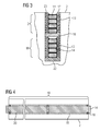
- FIG. 3 now simplifies the process of isolation essential.
- a groove 20 with a two-layer winding with the conductors I and II they are positioned and insulated by spacers according to the invention and a predetermined potting compound.
- a forming coil ie the conductor I or conductor II made of solid conductors or insulated wires, these form coils of the conductor I or conductor II then radially superimposed layered form part of the winding system 3, 6 and in certain sections, as in FIG. 4 shown to be provided with spacers 16.
- the structural design and the method is not limited to two-layer windings, but can also be realized in a single-layer or multi-layer winding.
- the sub-conductors 14 of a conductor can also be arranged next to one another and / or radially one above the other.
- a package with a spacer 16 is now first placed on the groove base 22 of the groove 20 and then a further spacer 16 is positioned with its conductor II on the first layer.
- This positioning ensures that the conductor II in the groove region 18 has an equidistant predetermined distance from the earthed laminated core of the stator 2 or rotor 5 over the entire axial length of the stator 2 or of the rotor 5.
- This can now be introduced by a potting in these remaining cavities of the groove 20, an insulating material, which forms a stable composite of the entire winding system 3.6 after curing. This simplifies the production just opposite to in FIG. 2 shown methodology and is far less error-prone.
- the spacer 16 is as in the present example according to FIG. 3 provided with a profiling, in particular with teeth, which facilitate fixing of the spacers 16 in the groove 20.
- the spacer 16 has - when it is placed on the slot opening - a Einrast researcher 17, wherein at least one tooth of the spacer 16 engages in an axially extending recess of the tooth of the laminated core.
- a slot closure strip 8 for covering the winding system 3, 6 in the groove 20 is therefore not absolutely necessary.
- spacers 16 can also be positioned in the groove 20 by adhesive bonds.
- FIG. 4 shows an electrical conductor in a groove 20 via the groove portion 18 axially distributed spacers 16 in the groove 20 are positioned to fix the conductor for the potting process.
Landscapes
- Engineering & Computer Science (AREA)
- Power Engineering (AREA)
- Manufacturing & Machinery (AREA)
- Insulation, Fastening Of Motor, Generator Windings (AREA)
- Manufacture Of Motors, Generators (AREA)
Priority Applications (5)
| Application Number | Priority Date | Filing Date | Title |
|---|---|---|---|
| EP13176305.4A EP2824801A1 (fr) | 2013-07-12 | 2013-07-12 | Procédé de fabrication d'une machine rotative dynamoélectrique et machine rotative dynamoélectrique |
| US14/904,272 US10424985B2 (en) | 2013-07-12 | 2014-07-08 | Method for producing a dynamoelectric rotary machine, and dynamoelectric rotary machine |
| CN201480036363.9A CN105324919B (zh) | 2013-07-12 | 2014-07-08 | 用于制造电动力旋转机器的方法和电动力旋转机器 |
| PCT/EP2014/064573 WO2015004119A1 (fr) | 2013-07-12 | 2014-07-08 | Procédé de fabrication d'une machine rotative dynamo-électrique et machine rotative dynamo-électrique associée |
| EP14741828.9A EP2992591B1 (fr) | 2013-07-12 | 2014-07-08 | Procédé de fabrication d'une machine rotative dynamoélectrique et machine rotative dynamoélectrique |
Applications Claiming Priority (1)
| Application Number | Priority Date | Filing Date | Title |
|---|---|---|---|
| EP13176305.4A EP2824801A1 (fr) | 2013-07-12 | 2013-07-12 | Procédé de fabrication d'une machine rotative dynamoélectrique et machine rotative dynamoélectrique |
Publications (1)
| Publication Number | Publication Date |
|---|---|
| EP2824801A1 true EP2824801A1 (fr) | 2015-01-14 |
Family
ID=48808172
Family Applications (2)
| Application Number | Title | Priority Date | Filing Date |
|---|---|---|---|
| EP13176305.4A Withdrawn EP2824801A1 (fr) | 2013-07-12 | 2013-07-12 | Procédé de fabrication d'une machine rotative dynamoélectrique et machine rotative dynamoélectrique |
| EP14741828.9A Not-in-force EP2992591B1 (fr) | 2013-07-12 | 2014-07-08 | Procédé de fabrication d'une machine rotative dynamoélectrique et machine rotative dynamoélectrique |
Family Applications After (1)
| Application Number | Title | Priority Date | Filing Date |
|---|---|---|---|
| EP14741828.9A Not-in-force EP2992591B1 (fr) | 2013-07-12 | 2014-07-08 | Procédé de fabrication d'une machine rotative dynamoélectrique et machine rotative dynamoélectrique |
Country Status (4)
| Country | Link |
|---|---|
| US (1) | US10424985B2 (fr) |
| EP (2) | EP2824801A1 (fr) |
| CN (1) | CN105324919B (fr) |
| WO (1) | WO2015004119A1 (fr) |
Cited By (3)
| Publication number | Priority date | Publication date | Assignee | Title |
|---|---|---|---|---|
| US20170104380A1 (en) * | 2015-10-08 | 2017-04-13 | Uqm Technologies, Inc. | Slot liner thermal conductivity for electric motors |
| AT523257A1 (de) * | 2018-05-29 | 2021-06-15 | Miba Emobility Gmbh | Stator mit Isolationsschicht |
| EP3945660A1 (fr) * | 2020-07-28 | 2022-02-02 | Siemens Aktiengesellschaft | Glissière d'un stator d'une machine dynamoélectrique |
Families Citing this family (19)
| Publication number | Priority date | Publication date | Assignee | Title |
|---|---|---|---|---|
| EP3073615A1 (fr) | 2015-03-26 | 2016-09-28 | Siemens Aktiengesellschaft | Dispositif autocollant de fermeture d'encoche pour une machine électrique |
| ES2637748T3 (es) | 2015-03-26 | 2017-10-16 | Siemens Aktiengesellschaft | Cierre de ranura expandible para una máquina eléctrica |
| EP3113334A1 (fr) * | 2015-07-02 | 2017-01-04 | Siemens Aktiengesellschaft | Machine rotative electrique encapsulee |
| KR102714659B1 (ko) | 2016-12-09 | 2024-10-07 | 엘지디스플레이 주식회사 | 전자 기기 |
| JP7218180B2 (ja) * | 2017-01-16 | 2023-02-06 | 本田技研工業株式会社 | 絶縁部材、回転電機のステータおよび回転電機 |
| JP6938933B2 (ja) * | 2017-02-03 | 2021-09-22 | トヨタ自動車株式会社 | 回転電機のステータ |
| GB201705833D0 (en) * | 2017-04-11 | 2017-05-24 | Cummins Generator Tech Ltd | Stator for electrical machine |
| JP6630710B2 (ja) * | 2017-10-05 | 2020-01-15 | 本田技研工業株式会社 | 回転電機のステータ及び絶縁紙 |
| DE102017218451A1 (de) * | 2017-10-16 | 2019-04-18 | Robert Bosch Gmbh | Stator und elektrische Maschine mit Stator |
| DE102017220123A1 (de) * | 2017-11-13 | 2019-05-16 | Audi Ag | Nutwandisolation für einen Stator eines Elektromotors |
| GB2571107A (en) * | 2018-02-16 | 2019-08-21 | Rolls Royce Plc | Metal coil fabrication |
| AT521060A1 (de) * | 2018-03-27 | 2019-10-15 | Miba Ag | Stator |
| AT521301B1 (de) | 2018-05-29 | 2020-04-15 | Miba Ag | Stator mit Isolationsschicht |
| DE102018219819A1 (de) * | 2018-11-19 | 2020-05-20 | Mahle International Gmbh | Elektrische Maschine, insbesondere für ein Fahrzeug |
| JP2022010425A (ja) * | 2020-04-24 | 2022-01-17 | 中川特殊鋼株式会社 | 回転電機のスロットコイル用絶縁材とその成形方法 |
| EP3910761A1 (fr) * | 2020-05-15 | 2021-11-17 | Siemens Aktiengesellschaft | Matière isolante de surface d'une machine dynamoélectrique |
| JP7562829B2 (ja) | 2020-07-31 | 2024-10-07 | コペンハーゲン アトミクス アーエス | 溶融塩原子炉用のキャンド回転動力式流体機械及び溶融塩原子炉用の流体機械用能動型磁気軸受 |
| AT524754A1 (de) * | 2021-03-12 | 2022-09-15 | Miba Emobility Gmbh | Maschinenbauteil |
| CN116094269A (zh) * | 2023-02-16 | 2023-05-09 | 兰州电机股份有限公司 | 一种电机纸盒槽绝缘嵌线工艺及铁芯嵌线结构 |
Citations (6)
| Publication number | Priority date | Publication date | Assignee | Title |
|---|---|---|---|---|
| US4200818A (en) * | 1978-08-01 | 1980-04-29 | Westinghouse Electric Corp. | Resin impregnated aromatic polyamide covered glass based slot wedge for large dynamoelectric machines |
| EP0379012A2 (fr) * | 1989-01-17 | 1990-07-25 | Siemens Aktiengesellschaft | Méthode pour la fabrication de stator d'une grosse machine électrique |
| EP0466893A1 (fr) * | 1990-02-06 | 1992-01-22 | Isovolta | Procede de fabrication de l'isolation electrique du bobinage d'un moteur electrique. |
| US5341561A (en) * | 1990-07-03 | 1994-08-30 | Isovolta Osterreichische Isolierstoffwerke Aktiengesellschaft | Process for producing the electric insulation of electric machine windings |
| DE10063146A1 (de) * | 1999-12-23 | 2001-09-13 | Valeo Equip Electr Moteur | Wechselstromgenerator für Fahrzeuge mit geräuscharmem Betrieb |
| US20090267441A1 (en) * | 2008-02-14 | 2009-10-29 | Hitachi, Ltd. | Rotating Electrical Machine |
Family Cites Families (15)
| Publication number | Priority date | Publication date | Assignee | Title |
|---|---|---|---|---|
| US1279810A (en) * | 1916-12-01 | 1918-09-24 | Allis Chalmers Mfg Co | Retaining-wedge for dynamo-electric machines. |
| DE2130201A1 (de) * | 1971-06-18 | 1972-12-21 | Kraftwerk Union Ag | Anordnung zur Fixierung der Staenderwicklungsstaebe elektrischer Maschinen,insbesondere bei Turbogeneratoren |
| US3943392A (en) | 1974-11-27 | 1976-03-09 | Allis-Chalmers Corporation | Combination slot liner and retainer for dynamoelectric machine conductor bars |
| US4149101A (en) * | 1977-05-12 | 1979-04-10 | Lesokhin Albert Z | Arrangement for locking slot wedges retaining electric windings |
| JPS61189153A (ja) | 1985-02-15 | 1986-08-22 | Hitachi Ltd | 回転電機のコイル固定方法 |
| EP0224694B1 (fr) | 1985-11-25 | 1990-05-16 | BBC Brown Boveri AG | Méthode pour la fabrication de l'enroulement d'une machine électrique |
| JP3621633B2 (ja) * | 2000-08-02 | 2005-02-16 | 三菱電機株式会社 | 回転電機の電機子およびその製造方法 |
| JP2005176482A (ja) | 2003-12-10 | 2005-06-30 | Fanuc Ltd | 電動機 |
| DE102005017111B4 (de) | 2005-04-13 | 2007-06-06 | Siemens Ag | Beschichtungsverfahren für einen Wickelkopf einer elektrischen Maschine |
| DE102005017112A1 (de) | 2005-04-13 | 2006-10-26 | Siemens Ag | Feuchtigkeitsabweisende Schutzschicht für einen Wickelkopf einer elektrischen Maschine |
| DE102005030877A1 (de) | 2005-07-01 | 2007-01-04 | Siemens Ag | Nutverschluss |
| DE102005055290B3 (de) | 2005-11-21 | 2007-05-03 | Siemens Ag | Glimmerverstärkter Isolierschlauch |
| JP2008017639A (ja) | 2006-07-06 | 2008-01-24 | Fanuc Ltd | 電動機および電動機製造方法 |
| JP5590045B2 (ja) | 2009-12-23 | 2014-09-17 | トヨタ自動車株式会社 | 回転電機のステータ構造 |
| JP5682603B2 (ja) * | 2012-08-10 | 2015-03-11 | 株式会社デンソー | 車両用回転電機の固定子 |
-
2013
- 2013-07-12 EP EP13176305.4A patent/EP2824801A1/fr not_active Withdrawn
-
2014
- 2014-07-08 WO PCT/EP2014/064573 patent/WO2015004119A1/fr not_active Ceased
- 2014-07-08 EP EP14741828.9A patent/EP2992591B1/fr not_active Not-in-force
- 2014-07-08 US US14/904,272 patent/US10424985B2/en active Active
- 2014-07-08 CN CN201480036363.9A patent/CN105324919B/zh not_active Expired - Fee Related
Patent Citations (6)
| Publication number | Priority date | Publication date | Assignee | Title |
|---|---|---|---|---|
| US4200818A (en) * | 1978-08-01 | 1980-04-29 | Westinghouse Electric Corp. | Resin impregnated aromatic polyamide covered glass based slot wedge for large dynamoelectric machines |
| EP0379012A2 (fr) * | 1989-01-17 | 1990-07-25 | Siemens Aktiengesellschaft | Méthode pour la fabrication de stator d'une grosse machine électrique |
| EP0466893A1 (fr) * | 1990-02-06 | 1992-01-22 | Isovolta | Procede de fabrication de l'isolation electrique du bobinage d'un moteur electrique. |
| US5341561A (en) * | 1990-07-03 | 1994-08-30 | Isovolta Osterreichische Isolierstoffwerke Aktiengesellschaft | Process for producing the electric insulation of electric machine windings |
| DE10063146A1 (de) * | 1999-12-23 | 2001-09-13 | Valeo Equip Electr Moteur | Wechselstromgenerator für Fahrzeuge mit geräuscharmem Betrieb |
| US20090267441A1 (en) * | 2008-02-14 | 2009-10-29 | Hitachi, Ltd. | Rotating Electrical Machine |
Cited By (5)
| Publication number | Priority date | Publication date | Assignee | Title |
|---|---|---|---|---|
| US20170104380A1 (en) * | 2015-10-08 | 2017-04-13 | Uqm Technologies, Inc. | Slot liner thermal conductivity for electric motors |
| AT523257A1 (de) * | 2018-05-29 | 2021-06-15 | Miba Emobility Gmbh | Stator mit Isolationsschicht |
| EP3945660A1 (fr) * | 2020-07-28 | 2022-02-02 | Siemens Aktiengesellschaft | Glissière d'un stator d'une machine dynamoélectrique |
| WO2022023043A1 (fr) * | 2020-07-28 | 2022-02-03 | Siemens Aktiengesellschaft | Cales d'encoche pour un stator d'une machine dynamo-électrique |
| US12328049B2 (en) | 2020-07-28 | 2025-06-10 | Hottinger Brüel & Kjaer GmbH | Slot wedge for a stator of a dynamo-electric machine |
Also Published As
| Publication number | Publication date |
|---|---|
| CN105324919A (zh) | 2016-02-10 |
| US10424985B2 (en) | 2019-09-24 |
| EP2992591A1 (fr) | 2016-03-09 |
| EP2992591B1 (fr) | 2017-11-29 |
| US20160156241A1 (en) | 2016-06-02 |
| CN105324919B (zh) | 2018-07-17 |
| WO2015004119A1 (fr) | 2015-01-15 |
Similar Documents
| Publication | Publication Date | Title |
|---|---|---|
| EP2992591B1 (fr) | Procédé de fabrication d'une machine rotative dynamoélectrique et machine rotative dynamoélectrique | |
| AT521301B1 (de) | Stator mit Isolationsschicht | |
| EP3871319B1 (fr) | Isolation des conducteurs partiels d'une machine dynamoélectrique | |
| EP2071707A1 (fr) | Machine dynamoélectrique dotée de bobines dentées | |
| DE102017206597A1 (de) | Polzahnmodul für eine elektrische Maschine, Aktivteil mit einem Polzahnmodul und elektrische Maschine | |
| DE102021100304A1 (de) | Elektromotor mit im Spritzgussverfahren umspritzten Stator | |
| EP1573883B1 (fr) | Element d'isolement elastique extrude de conducteurs de machines electriques | |
| DE102020208130A1 (de) | Wicklungssystem für eine elektrische Maschine | |
| DE102014222608A1 (de) | Rotor oder Stator mit gestecktem flachem Wickelkopf | |
| WO2018015055A1 (fr) | Machine synchrone électrique et procédé de fabrication au moins partiellement périphérique d'une machine électrique synchrone | |
| DE102012206039A1 (de) | Elektrische Maschine und Verfahren zur Herstellung einer elektrischen Maschine | |
| EP3073616B1 (fr) | Fermeture à encoche extensible pour une machine électrique | |
| DE102006048967A1 (de) | Stator für eine elektrische Maschine | |
| DE102013205240A1 (de) | Rotor oder Stator für eine elektrische Maschine und Verfahren zu seiner Herstellung | |
| DE102020215611A1 (de) | Verfahren zum Herstellen einer Luftspule sowie eine elektrische Maschine mit einer Luftspule hergestellt nach diesem Verfahren | |
| EP3151248A1 (fr) | Systeme d'isolation pour une machine electrique | |
| EP3621182A1 (fr) | Bobine dentée et procédé de fabrication d'une bobine dentée | |
| DE102022214072A1 (de) | Verfahren zur Herstellung einer elektrischen Maschine | |
| EP2882080B1 (fr) | Machine rotative dynamoélectrique | |
| DE102009046038A1 (de) | Spule aus härtbarem, flexiblen Litzenleiter | |
| EP4231502A1 (fr) | Stator pour une machine électrique et procédé de fabrication d'un tel stator | |
| EP3079242A1 (fr) | Procédé de fabrication de bobine autour d`un pole salisant pour une machine synchrone | |
| DE102023117311A1 (de) | Stator einer elektrischen Rotationsmaschine, Statoranordnung und elektrische Rotationsmaschine | |
| EP3072222A2 (fr) | Composant de machine pour machine électrique | |
| AT523257A1 (de) | Stator mit Isolationsschicht |
Legal Events
| Date | Code | Title | Description |
|---|---|---|---|
| 17P | Request for examination filed |
Effective date: 20130712 |
|
| AK | Designated contracting states |
Kind code of ref document: A1 Designated state(s): AL AT BE BG CH CY CZ DE DK EE ES FI FR GB GR HR HU IE IS IT LI LT LU LV MC MK MT NL NO PL PT RO RS SE SI SK SM TR |
|
| AX | Request for extension of the european patent |
Extension state: BA ME |
|
| PUAI | Public reference made under article 153(3) epc to a published international application that has entered the european phase |
Free format text: ORIGINAL CODE: 0009012 |
|
| STAA | Information on the status of an ep patent application or granted ep patent |
Free format text: STATUS: THE APPLICATION IS DEEMED TO BE WITHDRAWN |
|
| 18D | Application deemed to be withdrawn |
Effective date: 20150715 |