EP2824804A1 - Machine électrique à grande vitesse de rotation - Google Patents
Machine électrique à grande vitesse de rotation Download PDFInfo
- Publication number
- EP2824804A1 EP2824804A1 EP13176314.6A EP13176314A EP2824804A1 EP 2824804 A1 EP2824804 A1 EP 2824804A1 EP 13176314 A EP13176314 A EP 13176314A EP 2824804 A1 EP2824804 A1 EP 2824804A1
- Authority
- EP
- European Patent Office
- Prior art keywords
- rotor
- machine according
- electric machine
- stator
- shaft
- Prior art date
- Legal status (The legal status is an assumption and is not a legal conclusion. Google has not performed a legal analysis and makes no representation as to the accuracy of the status listed.)
- Withdrawn
Links
- 238000005096 rolling process Methods 0.000 claims abstract description 39
- 238000001816 cooling Methods 0.000 claims description 25
- 238000004804 winding Methods 0.000 claims description 15
- 238000003475 lamination Methods 0.000 claims description 13
- 230000007704 transition Effects 0.000 claims description 7
- 230000010355 oscillation Effects 0.000 claims description 6
- 229920002430 Fibre-reinforced plastic Polymers 0.000 claims description 4
- 239000011151 fibre-reinforced plastic Substances 0.000 claims description 4
- 239000000203 mixture Substances 0.000 claims description 4
- 230000001050 lubricating effect Effects 0.000 claims 1
- 238000013016 damping Methods 0.000 description 4
- 239000007921 spray Substances 0.000 description 2
- 230000002238 attenuated effect Effects 0.000 description 1
- 230000005540 biological transmission Effects 0.000 description 1
- 229910052799 carbon Inorganic materials 0.000 description 1
- 239000004918 carbon fiber reinforced polymer Substances 0.000 description 1
- 230000008878 coupling Effects 0.000 description 1
- 238000010168 coupling process Methods 0.000 description 1
- 238000005859 coupling reaction Methods 0.000 description 1
- 230000006378 damage Effects 0.000 description 1
- 230000001419 dependent effect Effects 0.000 description 1
- 238000002474 experimental method Methods 0.000 description 1
- 239000011152 fibreglass Substances 0.000 description 1
- 238000005461 lubrication Methods 0.000 description 1
- 238000000034 method Methods 0.000 description 1
- 239000003595 mist Substances 0.000 description 1
- 238000010248 power generation Methods 0.000 description 1
- 230000008569 process Effects 0.000 description 1
- 230000009467 reduction Effects 0.000 description 1
- 230000001360 synchronised effect Effects 0.000 description 1
Images


Classifications
-
- H—ELECTRICITY
- H02—GENERATION; CONVERSION OR DISTRIBUTION OF ELECTRIC POWER
- H02K—DYNAMO-ELECTRIC MACHINES
- H02K5/00—Casings; Enclosures; Supports
- H02K5/04—Casings or enclosures characterised by the shape, form or construction thereof
- H02K5/16—Means for supporting bearings, e.g. insulating supports or means for fitting bearings in the bearing-shields
- H02K5/173—Means for supporting bearings, e.g. insulating supports or means for fitting bearings in the bearing-shields using bearings with rolling contact, e.g. ball bearings
- H02K5/1732—Means for supporting bearings, e.g. insulating supports or means for fitting bearings in the bearing-shields using bearings with rolling contact, e.g. ball bearings radially supporting the rotary shaft at both ends of the rotor
-
- H—ELECTRICITY
- H02—GENERATION; CONVERSION OR DISTRIBUTION OF ELECTRIC POWER
- H02K—DYNAMO-ELECTRIC MACHINES
- H02K21/00—Synchronous motors having permanent magnets; Synchronous generators having permanent magnets
- H02K21/12—Synchronous motors having permanent magnets; Synchronous generators having permanent magnets with stationary armatures and rotating magnets
- H02K21/22—Synchronous motors having permanent magnets; Synchronous generators having permanent magnets with stationary armatures and rotating magnets with magnets rotating around the armatures, e.g. flywheel magnetos
-
- H—ELECTRICITY
- H02—GENERATION; CONVERSION OR DISTRIBUTION OF ELECTRIC POWER
- H02K—DYNAMO-ELECTRIC MACHINES
- H02K2213/00—Specific aspects, not otherwise provided for and not covered by codes H02K2201/00 - H02K2211/00
- H02K2213/03—Machines characterised by numerical values, ranges, mathematical expressions or similar information
-
- H—ELECTRICITY
- H02—GENERATION; CONVERSION OR DISTRIBUTION OF ELECTRIC POWER
- H02K—DYNAMO-ELECTRIC MACHINES
- H02K9/00—Arrangements for cooling or ventilating
- H02K9/02—Arrangements for cooling or ventilating by ambient air flowing through the machine
- H02K9/04—Arrangements for cooling or ventilating by ambient air flowing through the machine having means for generating a flow of cooling medium
Definitions
- gas turbines For power generation in aircraft gas turbines are often used in the prior art.
- the gas turbines are only energy-efficient if they are operated in the range of their nominal power and thus in the range of their rated speed.
- the rated power is usually required only in very few flight phases, especially at start. It is therefore possible to improve the overall efficiency by having a gas turbine drive a generator.
- the electrical energy generated thereby can be distributed and fed to electric motors, which in turn drive propellers.
- the rated speed of gas turbines varies depending on the size of the gas turbine between a few 1000 revolutions / min to far over 30,000 revolutions / min. Partial rated speeds up to 55,000 revolutions / min are achieved.
- electrical machines for this speed range (30000 revolutions / min and more) are known as drives for dental instruments.
- such electrical machines are operated as electric motors with a low power consumption (a few watts) - so-called micromotors.
- a simple scaling of such an electric machine in the power range nominal power several kilowatts or even over one megawatt) is not possible.
- the biggest problem is that the electrical machine must be operated above some natural frequencies of the system, so that excited natural oscillations must be effectively damped.
- the object of the present invention is to provide an electric machine for the power range, which is operable at extremely high speeds.
- roller bearing against statorfest arranged end shields based on the axis of rotation, axially and radially resiliently biased by means of elastic intermediate elements.
- bearing bushes are arranged between the roller bearings and the end shields and the elastic intermediate elements are arranged between the bearing bushes and the end shields.
- the rolling bearings are each biased by a plurality of elastic intermediate elements radially elastic and each biased axially elastically by means of at least one elastic intermediate element.
- This embodiment has proven to be particularly efficient in experiments.
- the rotor shaft in the region of the rotor has a first shaft diameter and tapers toward the roller bearings in transition sections to a second shaft diameter.
- a stator winding is arranged in the stator, which has axially on both sides of the stator each projecting beyond the stator winding head.
- the transition sections are arranged in the region of the winding heads.
- a turbine shaft of a turbine - When coupling the rotor shaft with a drive shaft - for example, a turbine shaft of a turbine - must be expected that a radial offset and / or an angular offset between the drive shaft and the rotor shaft occurs. Such an offset can lead to radial vibrations and wobbling movements of the rotor shaft. In extreme cases, the excited vibrations can be so strong that the risk of contact of the stator by the rotor is. In such a case, the electric machine would be destroyed.
- catch bearings are preferably arranged in the end shields in addition to the rolling bearings, with respect to the bearing plates at least are arranged radially inelastically.
- the fishing camps limit a tilt and an offset of the rotor shaft to a respective maximum value.
- the backup bearings are designed so that the rotor remains spaced even at the maximum tilt and also at the maximum offset from the stator.
- the safety bearings are arranged in safety bearings.
- the rolling bearings against the - inelastic and stationary held in the bearing shields - Fanglagerhalterungen are axially biased.
- the elastic bias of the rolling bearing is preferably determined such that - based on a period of oscillation of an axial and / or radial vibration - an attenuation of at least 0.15 is achieved.
- the attenuation is even at least 0.20, in particular at least 0.25.
- the rotor has an outer diameter and a length.
- a ratio of the length to the outer diameter is preferably at least 3: 1.
- the rotor comprises, as is common practice, a rotor core, which consists of a plurality of axially rotatably stacked to the rotation axis, annularly shaped rotor laminations.
- the rotor laminated core has a radial extent as seen radially with respect to the axis of rotation.
- the radial extent of the rotor lamination stack is preferably between 5% and 10% of a first shaft diameter which the rotor shaft has in the area of the rotor lamination stack. For example, at a first shaft diameter of 70 mm, the radial extent may be about 5 mm.
- the rotor laminations have a maximum thickness of 0.25 mm in the direction of the axis of rotation, for example a maximum thickness of 0.20 mm, in particular of not more than 0.15 mm.
- the rotor core is usually shrunk onto the rotor shaft.
- the rotor shaft preferably has a projection which is axially adjacent to the rotor laminated core at one end of the rotor.
- the rotor shaft has no such projection. This makes it possible to quickly postpone the rotor laminated core to the projection on the rotor shaft and then to shrink (especially by cooling) on the rotor shaft.
- the projection can rotate in a ring around the rotor shaft.
- the electric machine is preferably designed as a permanently excited electric synchronous machine. Therefore, permanent magnets are arranged on the radial outer side of the rotor laminated core.
- the rotor preferably has a casing of a fiber-reinforced plastic which surrounds the rotor laminated core and the permanent magnets radially on the outside.
- a fiber-reinforced plastic in particular a glass fiber reinforced plastic and a carbon fiber reinforced plastic come into question.
- a radial thickness of the shell is usually in the range of a few millimeters.
- an oil-air mixture is supplied.
- Such oil-air mixtures can be realized in particular in the form of a so-called spray cooling.
- those outlet openings through which the cooling air blown into one of the intermediate spaces is blown out are arranged between the other intermediate space and those outlet openings through which the cooling air blown into the other intermediate space is blown out.
- the cooling of the stator can be further improved in that radial recesses are introduced into the stator, via which the channels are communicatively connected to an air gap between the stator and the rotor.
- the rotor can be cooled with.
- the electrical machine is designed as a sensorless electric machine.
- the electric machine is preferably designed as a two-pole electric machine.
- the gas turbine has a rated speed of at least 40,000 revolutions / min.
- the rated speed may be even greater, for example up to 45,000 revolutions per minute, up to 50,000 revolutions per minute or up to 55,000 revolutions per minute. In some cases even higher rated speeds are possible.
- an electric machine generally designated by the reference numeral 1 has a rotor 2.
- the rotor 2 is rotatably mounted on a rotor shaft 3.
- the rotor shaft 3 in turn is mounted in bearings 4, so that it is rotatable about a rotation axis 5.
- the rolling bearings 4 are according to FIG. 1 designed as a ball bearing. However, this is not mandatory.
- the rolling bearing 4 could alternatively be designed, for example, as a roller bearing or as a needle bearing.
- axial is a direction parallel to the axis of rotation 5.
- Radial is a direction orthogonal to the axis of rotation 5 directly on the axis of rotation 5 to or away from it.
- Tortal is a direction that is orthogonal to both the axial and radial directions. “Tangential” is thus a direction which is directed at a constant axial position and at a constant radial distance from the rotation axis 5 in a circle around the axis of rotation 5 around.
- the rotor 2 is surrounded radially on the outside by a stator 6 of the electric machine 1.
- a stator winding is arranged, from the in FIG. 1 only winding heads 7 visible are axially projecting axially on both sides of the stator 6 via the stator 7.
- the stator 6 in turn is surrounded radially on the outside by a housing 8.
- bearing plates 9 are arranged on the housing 8 bearing plates 9 are arranged.
- the end shields 9 are arranged statorfest due to their arrangement on the housing 8.
- the bearings 4 are compared to the bearing plate 9 by means of elastic intermediate elements 10, 11 axially and radially elastically biased.
- the intermediate elements 10, 11 may be formed for example as O-rings.
- bearing bushes 12 are arranged between the rolling bearings 4 and the bearing plates.
- the rolling bearings 4 are arranged inelastically in the bearing bushes 12.
- the elastic intermediate elements 10, 11 are arranged between the bearing bushes 12 and the end shields 9.
- FIG. 1 are the rolling bearing 4 (or the bearing bushes 12) each biased by a plurality of elastic intermediate elements 10 radially elastic.
- the presence of a plurality of elastic intermediate elements 10 for generating the radially elastic prestress is preferred.
- the axially elastic bias is according to FIG. 1 each effected by means of a single elastic intermediate element 11.
- the rotor shaft 3 has according to FIG. 1 in the region of the rotor 2, a first shaft diameter d1.
- the first shaft diameter d1 may, for example, be in the range between 50 mm and 100 mm, preferably in the range between 60 mm and 80 mm. In particular, the first shaft diameter d1 may, for example, be approximately 70 mm.
- the rotor shaft 3 has a second shaft diameter d2, which is smaller than the first shaft diameter d1.
- the rotor shaft 3 therefore tapers in transition sections 13 from the first shaft diameter d1 to the second shaft diameter d2.
- the second shaft diameter d2 can For example, between 35% and 65% of the first shaft diameter d1, preferably between 40% and 60%, in particular between 45% and 55%.
- the transition sections 13 may be stepped. Alternatively, as shown in FIG FIG. 1 tapered.
- the transition sections 13 can be arranged as needed. In particular, as shown in FIG. 1 be arranged in the axial direction in the region of the winding heads 7.
- the bearing plates 9 preferably have ring-like projections 14, which, viewed in the axial direction, extend to the stator 6.
- the bushings 12 may be arranged in this case in the annular projections 14. Depending on how far the annular projections 14 extend in the axial direction on the stator 6, it is even possible that the rolling bearing 4 as shown in FIG FIG. 1 seen in the axial direction in the region of the winding heads 7 are arranged.
- 9 catch bearings 15 are arranged in addition to the rolling bearings 4 in the bearing plates.
- the fishing camps 15 are arranged at least radially inelastisch with respect to the bearing plates 9. Most of the fishing camp 15 are also arranged axially inelastic with respect to the bearing plates 9.
- the fishing camps 15 are not active during normal operation of the electric machine 1. However, if a tilting and / or an offset of the rotor shaft 3 occur relative to the axis of rotation 5 and reach a maximum value, the backup bearings 15 are active. The fishing camps 15 thereby limit the tilting and the offset of the rotor shaft 3 to the respective maximum value.
- the backup bearings 15 are designed (i.e., the maximum values determined accordingly) so that the rotor 2 remains spaced from the stator 6 even at the maximum tilt and also at the maximum offset.
- the fishing camps 15 are according to FIG. 1 arranged in fishing camp supports 16. If the fishing camps 15 are also axially inelastically held by means of the fishing camp supports 16 with respect to the end shields 9, the rolling bearings 4 are preferably axially biased against the fishing camp supports 16.
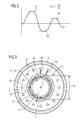
- the elastic bias can according to FIG. 2 in particular be determined such that an attenuation D of at least 0.15 is achieved.
- the damping D is even at least 0.20, in particular at least 0.25.
- the damping D results according to FIG. 2 by the decrease of the elongation of the damped vibration.
- the damping D is thus related to a period of oscillation of an axial and / or radial vibration.
- the possible power output of the electric machine 1 increases with an outer diameter d3 of the rotor 2. With increasing outer diameter d3 of the rotor 2, however, centrifugal forces acting on the rotor 2 also increase.
- the outer diameter d3 of the rotor 2 should therefore be optimally selected.
- the possible power output of the electric machine 1 is proportional to a length 1 of the rotor 2. It has proved to be advantageous that a ratio of the length 1 to the outer diameter d3 is at least 3: 1.
- the length 1 should therefore be at least three times the outer diameter d3. Preferably, it is even at least four times. However, the fivefold should not be exceeded.
- the rotor 2 comprises according to the FIG. 1 and 3 a rotor laminated core 17.
- the rotor core 17 consists of a plurality of rotor plates 18.
- the rotor plates 18 are axially stacked on each other and formed annular.
- the rotor core 17 has a radial extent ⁇ r radially.
- the radial extent ⁇ r is preferably between 5% and 10% of the first shaft diameter d1.
- the rotor laminations 18 are preferably relatively thin, viewed in the axial direction. In particular, they have according to FIG. 1 preferably a thickness d of at most 0.25 mm.
- the thickness d can be a maximum of 0.20 mm, in particular a maximum of 0.15 mm.
- the rotor core 17 is preferably shrunk onto the rotor shaft 3.
- the rotor shaft 3 preferably has a projection 19.
- the rotor laminated core 17 can be pushed up to the projection 19 on the rotor shaft 3 and held there until the Aufschrumpfvorgang is completed. Due to the pushing on of the rotor laminated core 17, one end of the rotor core 17 abuts axially against the projection 19.
- the rotor shaft 3 has no such projection, since otherwise the pushing on of the rotor lamination stack 17 would not be possible.
- permanent magnets 20 are arranged on the radial outer side of the rotor laminated core.
- the rotor core 17 and the permanent magnets 20 are - see also FIG. 1 - Again preferably surrounded radially outwardly by a sheath 21.
- the sheath 21 is preferably made of a fiber-reinforced plastic.
- the rolling bearings 4 are preferably cooled and / or lubricated.
- the rolling bearings 4 according to FIG. 1 via a respective supply line 22, an oil-air mixture 23 is supplied.
- an oil-air mixture 23 is supplied.
- a temperature difference between the bearing inner rings of the rolling bearing 4 and the bearing outer rings of the rolling bearing 4 can be limited to a few ° C, in particular to 10 ° C and less.
- the bearing plates 9 openings 24.
- cooling air is blown into a respective intermediate space 26 between the respective end shield 9 and the stator 6 via a fan 25 from the outside.
- the stator 6 (see FIG. 3 ) axially extending channels 27.
- the cooling air is guided through the channels 27 to respective outlet openings 28 which are arranged in the housing 8. Via the outlet openings 28, the blown in the respective intermediate space 26 cooling air is blown out of the electric machine 1.
- the channels 27 extend, starting from the respective intermediate space 26, beyond the center of the stator 6. Consequently, in the axial direction, those outlet openings 28 through which the cooling air blown into the one space 26 is blown out, as shown in FIG FIG. 4 disposed between the other space 26 and those outlet openings 28 through which the blown in the other space 26 cooling air is blown out.
- the winding heads 7, the stator 6 and also the bearing bushes 12 are efficiently cooled. Cooling of the rotor 2 takes place only indirectly. If an improved cooling of the stator 6 and / or a cooling of the rotor 2 is required, can be in the stator 6 as shown in FIG. 3 additionally radial recesses 29 may be introduced. Via the radial recesses 29, the channels 27 are communicatively connected to an air gap 30. The air gap 30 is formed between the stator 6 and the rotor 2.
- the electric machine 1 is intended for power applications. It is therefore both in terms of their dimensions and in terms of their power rating as well as with respect to their mass M (see FIG. 5 ) not comparable to a micromotor.
- a length L of the electric machine is usually at least 50 cm, often 70 cm and more. Also, a length L of 1 m and more is quite possible.
- a housing diameter d4 is usually at least 15 cm, often 20 cm and more. Also, a housing diameter d4 of 25 cm or 30 cm or even more is quite possible.
- a rated power of the electric machine 1 is often in two or three digits Kilowatt range, in particular at least 50 kW, at least 100 kW or at least 200 kW. Also a nominal power of 1 MW and more is possible. Accordingly, the mass M is worth mentioning. It is usually in the range between at least 6 kg for a small rated power of, for example, 30 kW and up to 250 kg with a high rated power above 1 MW.
- FIG. 5 shows a preferred use of the electric machine according to the invention, namely in the context of a combined turbine-generator unit.
- the turbine-generator unit has a gas turbine 31, which in turn has a turbine shaft 32.
- the turbine-generator unit furthermore has an electrical machine 1.
- the electric machine 1 is formed as explained above.
- the gas turbine 31 is a relatively small, but very high speed running gas turbine 31. In particular, it has a rated speed of at least 40000 revolutions / min. It may also have an even higher rated speed, for example at least 45,000 rpm, at least 50,000 rpm or even up to 55,000 rpm.
- the turbine shaft 32 is directly - so without rotation of a transmission - with the rotor shaft 3 of the electric machine 1 rotatably connected. The turbine shaft 32 and the rotor shaft 3 thus always rotate at the same speed.
- the electric machine 1 is within the scope of the preferred use of FIG. 5 operated only in a single operating point (namely at rated speed or at least near the rated speed). It can therefore be designed as an encoderless electric machine 1. Furthermore, in particular during operation of the electric machine 1 at high rotational speeds, it had proven advantageous to design the electric machine 1 as a two-pole electrical machine 1.
- the present invention relates to an electric machine 1, which has a rotor 2 which is arranged rotationally fixed on a rotor shaft 3.
- the rotor shaft 3 is mounted in rolling bearings 4, so that it is rotatable about a rotation axis 5.
- the rotor 2 is surrounded radially on the outside by a stator 6 of the electric machine.
- the rolling bearing 4 are biased against statorfest arranged bearing plates 9 by means of elastic intermediate elements 10, 11 axially and radially elastic.
- the electric machine 1 has many advantages.
- the electric machine 1 offers a high power-to-weight ratio (more than 5 kW / kg) and can also be operated in continuous operation at very high rotational speeds (40,000 revolutions / min and more).
Landscapes
- Engineering & Computer Science (AREA)
- Power Engineering (AREA)
- Motor Or Generator Frames (AREA)
Priority Applications (1)
| Application Number | Priority Date | Filing Date | Title |
|---|---|---|---|
| EP13176314.6A EP2824804A1 (fr) | 2013-07-12 | 2013-07-12 | Machine électrique à grande vitesse de rotation |
Applications Claiming Priority (1)
| Application Number | Priority Date | Filing Date | Title |
|---|---|---|---|
| EP13176314.6A EP2824804A1 (fr) | 2013-07-12 | 2013-07-12 | Machine électrique à grande vitesse de rotation |
Publications (1)
| Publication Number | Publication Date |
|---|---|
| EP2824804A1 true EP2824804A1 (fr) | 2015-01-14 |
Family
ID=48808174
Family Applications (1)
| Application Number | Title | Priority Date | Filing Date |
|---|---|---|---|
| EP13176314.6A Withdrawn EP2824804A1 (fr) | 2013-07-12 | 2013-07-12 | Machine électrique à grande vitesse de rotation |
Country Status (1)
| Country | Link |
|---|---|
| EP (1) | EP2824804A1 (fr) |
Cited By (2)
| Publication number | Priority date | Publication date | Assignee | Title |
|---|---|---|---|---|
| CN108173381A (zh) * | 2018-02-05 | 2018-06-15 | 宁夏巨能机器人股份有限公司 | 一种用于铸造砂芯搬运桁架机器手的直驱电机 |
| CN113098186A (zh) * | 2021-05-24 | 2021-07-09 | 台州立克科技有限公司 | 一种可调式减震电机 |
Citations (4)
| Publication number | Priority date | Publication date | Assignee | Title |
|---|---|---|---|---|
| US3264503A (en) * | 1965-04-05 | 1966-08-02 | Sandoz Ltd | High speed electric motors |
| WO2007124982A2 (fr) * | 2006-04-28 | 2007-11-08 | Siemens Aktiengesellschaft | Palier d'arrêt pour une machine électrique et machine électrique pourvue d'au moins un palier d'arrêt de ce type |
| WO2011144323A1 (fr) * | 2010-05-19 | 2011-11-24 | Eppendorf Ag | Amortissement de vibrations pour un dispositif électrique |
| EP2602916A1 (fr) * | 2011-12-06 | 2013-06-12 | Hamilton Sundstrand Space Systems International, Inc. | Refroidissement de machine électrique à aimant permanent |
-
2013
- 2013-07-12 EP EP13176314.6A patent/EP2824804A1/fr not_active Withdrawn
Patent Citations (4)
| Publication number | Priority date | Publication date | Assignee | Title |
|---|---|---|---|---|
| US3264503A (en) * | 1965-04-05 | 1966-08-02 | Sandoz Ltd | High speed electric motors |
| WO2007124982A2 (fr) * | 2006-04-28 | 2007-11-08 | Siemens Aktiengesellschaft | Palier d'arrêt pour une machine électrique et machine électrique pourvue d'au moins un palier d'arrêt de ce type |
| WO2011144323A1 (fr) * | 2010-05-19 | 2011-11-24 | Eppendorf Ag | Amortissement de vibrations pour un dispositif électrique |
| EP2602916A1 (fr) * | 2011-12-06 | 2013-06-12 | Hamilton Sundstrand Space Systems International, Inc. | Refroidissement de machine électrique à aimant permanent |
Cited By (4)
| Publication number | Priority date | Publication date | Assignee | Title |
|---|---|---|---|---|
| CN108173381A (zh) * | 2018-02-05 | 2018-06-15 | 宁夏巨能机器人股份有限公司 | 一种用于铸造砂芯搬运桁架机器手的直驱电机 |
| CN108173381B (zh) * | 2018-02-05 | 2024-02-13 | 宁夏巨能机器人股份有限公司 | 一种用于铸造砂芯搬运桁架机器手的直驱电机 |
| CN113098186A (zh) * | 2021-05-24 | 2021-07-09 | 台州立克科技有限公司 | 一种可调式减震电机 |
| CN113098186B (zh) * | 2021-05-24 | 2022-11-04 | 台州立克科技有限公司 | 一种可调式减震电机 |
Similar Documents
| Publication | Publication Date | Title |
|---|---|---|
| DE60116899T2 (de) | Rotierende maschine mit axialem magnetischem anschlag, der einen stromgenerator beinhaltet | |
| WO2007107399A1 (fr) | Machine électrique, notamment générateur | |
| WO2001065670A1 (fr) | Unite de production de courant constituee d'un moteur de commande et d'un generateur | |
| DE2445217A1 (de) | Dynamoelektrische maschine mit supraleitender feldwicklung | |
| EP2991207A1 (fr) | Machine dynamoélectrique équipée de rotor à aimant permanent et à réluctance | |
| DE102015110652B4 (de) | Rotor-stator-anordnung für eine hybriderregte synchronmaschine und ein rotor dafür | |
| DE102016216181B4 (de) | Rotierende elektrische Maschine | |
| EP2770616A1 (fr) | Machine électrique avec stator séparé | |
| EP2989713B1 (fr) | Accumulateur d'énergie cinétique et dispositif d'alimentation d'énergie électrique sans interruptions | |
| DE102021101408A1 (de) | Elektrische maschine, antriebssystem und dessen verwendung | |
| EP1977499A1 (fr) | Moteur à réaction avec support magnétique actif | |
| DE102019214519A1 (de) | Elektrische Maschine mit einstellbarem Luftspalt | |
| EP1936786A2 (fr) | Machine électrique à limitation de couple | |
| EP2697892B1 (fr) | Machine asynchrone | |
| EP2824804A1 (fr) | Machine électrique à grande vitesse de rotation | |
| DE102014223527A1 (de) | Kühlung eines axialen Endbereichs eines Stators einer rotierenden elektrischen Maschine | |
| EP3284157B1 (fr) | Éolienne et empilage de tôles polaires pour un générateur synchrone d'une éolienne ainsi que générateur synchrone | |
| EP0766884A1 (fr) | Systeme de refroidissement pour moteur | |
| AT512853B1 (de) | Differentialantrieb für eine Energiegewinnungsanlage | |
| EP2273651A1 (fr) | Machine électrique | |
| DE102011000420B4 (de) | Turbo-Generator-Einheit | |
| DE102009020092A1 (de) | Elektrische Maschine | |
| AT15743U1 (de) | Elektrische Turbomaschine und Energiewandler | |
| EP3912256B1 (fr) | Moteur électrique | |
| DE102019206064A1 (de) | Rotoranordnung und elektrische Maschine |
Legal Events
| Date | Code | Title | Description |
|---|---|---|---|
| 17P | Request for examination filed |
Effective date: 20130712 |
|
| AK | Designated contracting states |
Kind code of ref document: A1 Designated state(s): AL AT BE BG CH CY CZ DE DK EE ES FI FR GB GR HR HU IE IS IT LI LT LU LV MC MK MT NL NO PL PT RO RS SE SI SK SM TR |
|
| AX | Request for extension of the european patent |
Extension state: BA ME |
|
| PUAI | Public reference made under article 153(3) epc to a published international application that has entered the european phase |
Free format text: ORIGINAL CODE: 0009012 |
|
| R17P | Request for examination filed (corrected) |
Effective date: 20150714 |
|
| RBV | Designated contracting states (corrected) |
Designated state(s): AL AT BE BG CH CY CZ DE DK EE ES FI FR GB GR HR HU IE IS IT LI LT LU LV MC MK MT NL NO PL PT RO RS SE SI SK SM TR |
|
| RAP1 | Party data changed (applicant data changed or rights of an application transferred) |
Owner name: SIEMENS AKTIENGESELLSCHAFT |
|
| GRAP | Despatch of communication of intention to grant a patent |
Free format text: ORIGINAL CODE: EPIDOSNIGR1 |
|
| INTG | Intention to grant announced |
Effective date: 20180306 |
|
| STAA | Information on the status of an ep patent application or granted ep patent |
Free format text: STATUS: THE APPLICATION IS DEEMED TO BE WITHDRAWN |
|
| 18D | Application deemed to be withdrawn |
Effective date: 20180717 |