EP2824811A1 - Enroulement de stator traversant enroulé sur un support de bobine - Google Patents
Enroulement de stator traversant enroulé sur un support de bobine Download PDFInfo
- Publication number
- EP2824811A1 EP2824811A1 EP13176073.8A EP13176073A EP2824811A1 EP 2824811 A1 EP2824811 A1 EP 2824811A1 EP 13176073 A EP13176073 A EP 13176073A EP 2824811 A1 EP2824811 A1 EP 2824811A1
- Authority
- EP
- European Patent Office
- Prior art keywords
- stator
- carrier
- coil
- central axis
- phase
- Prior art date
- Legal status (The legal status is an assumption and is not a legal conclusion. Google has not performed a legal analysis and makes no representation as to the accuracy of the status listed.)
- Withdrawn
Links
Images




Classifications
-
- H—ELECTRICITY
- H02—GENERATION; CONVERSION OR DISTRIBUTION OF ELECTRIC POWER
- H02K—DYNAMO-ELECTRIC MACHINES
- H02K3/00—Details of windings
- H02K3/46—Fastening of windings on the stator or rotor structure
- H02K3/52—Fastening salient pole windings or connections thereto
- H02K3/521—Fastening salient pole windings or connections thereto applicable to stators only
- H02K3/522—Fastening salient pole windings or connections thereto applicable to stators only for generally annular cores with salient poles
-
- H—ELECTRICITY
- H02—GENERATION; CONVERSION OR DISTRIBUTION OF ELECTRIC POWER
- H02K—DYNAMO-ELECTRIC MACHINES
- H02K15/00—Processes or apparatus specially adapted for manufacturing, assembling, maintaining or repairing of dynamo-electric machines
- H02K15/06—Embedding prefabricated windings in the machines
- H02K15/062—Windings in slots; Salient pole windings
- H02K15/065—Windings consisting of complete sections, e.g. coils or waves
-
- H—ELECTRICITY
- H02—GENERATION; CONVERSION OR DISTRIBUTION OF ELECTRIC POWER
- H02K—DYNAMO-ELECTRIC MACHINES
- H02K15/00—Processes or apparatus specially adapted for manufacturing, assembling, maintaining or repairing of dynamo-electric machines
- H02K15/06—Embedding prefabricated windings in the machines
- H02K15/062—Windings in slots; Salient pole windings
- H02K15/065—Windings consisting of complete sections, e.g. coils or waves
- H02K15/066—Windings consisting of complete sections, e.g. coils or waves inserted perpendicularly to the axis of the slots or inter-polar channels
-
- H—ELECTRICITY
- H02—GENERATION; CONVERSION OR DISTRIBUTION OF ELECTRIC POWER
- H02K—DYNAMO-ELECTRIC MACHINES
- H02K3/00—Details of windings
- H02K3/04—Windings characterised by the conductor shape, form or construction, e.g. with bar conductors
- H02K3/28—Layout of windings or of connections between windings
-
- H—ELECTRICITY
- H02—GENERATION; CONVERSION OR DISTRIBUTION OF ELECTRIC POWER
- H02K—DYNAMO-ELECTRIC MACHINES
- H02K3/00—Details of windings
- H02K3/32—Windings characterised by the shape, form or construction of the insulation
- H02K3/325—Windings characterised by the shape, form or construction of the insulation for windings on salient poles, such as claw-shaped poles
-
- H—ELECTRICITY
- H02—GENERATION; CONVERSION OR DISTRIBUTION OF ELECTRIC POWER
- H02K—DYNAMO-ELECTRIC MACHINES
- H02K2203/00—Specific aspects not provided for in the other groups of this subclass relating to the windings
- H02K2203/12—Machines characterised by the bobbins for supporting the windings
Definitions
- the present invention relates to a stator winding manufacturing method of a stator having a plurality of stator teeth projecting radially outward from a connecting structure revolving around a radial axis of a stator center axis about a central axis of the stator.
- Such a stator may for example be the stator of an external rotor.
- the stator may be the inner part of a so-called star yoke package.
- a star yoke package is from the EP 2 549 622 A1 known.
- the coil supports are individually wound with a respective conductor wire. Thereafter, the coil carriers are attached to the stator teeth. In the case of a star yoke package trained stator then the yoke is pushed onto the star. Thereafter, the so-called phase separator are injected, the circuit carrier attached and connected within the circuit substrate, the conductor wires of the individually wound on the coil carrier conductor wires together.
- connection of the conductor wires of the individual coils with each other is technically complex and error prone. If done manually, it is also time consuming and cumbersome.
- the object of the present invention is to provide ways to switch a stator having outwardly projecting stator teeth in a simpler manner.
- the pivoting can be designed as needed.
- the bobbin for pivoting on the stator teeth are pivoted by at least 90 ° about the respective pivot axis. From this angle, the coil carrier for winding with the respective conductor wire are easily accessible. In particular, they can be pivoted through 180 ° about the respective pivot axis.
- This embodiment is particularly compact.
- the bobbins in this case are arranged in a similar configuration as after pivoting on the auxiliary member.
- the pivoting movement may be a pure pivoting movement, so that the last section of the movement of the coil carrier is also a pivoting movement.
- the respective coil carrier can be positioned immediately before the respective stator tooth when the pivoting movement is ended, so that the last movement section is a pushing on of the respective coil carrier onto the respective stator tooth.
- the conductor wires of the phases are preferably guided without crossing in the circuit carrier.
- the conductor wires of the phases in the circuit carrier from phase to phase can alternatively be performed radially or axially offset.
- the circuit carrier preferably has a partial carrier per phase.
- first one of the sub-carriers is arranged on the auxiliary element.
- the respective next subcarrier is placed after the winding of the conductor wire to the coils of the respective phase on the respective preceding subcarrier.
- the coil carriers there is no direct connection of the coil carrier to the circuit carrier.
- the coil carriers each have a hinge, via which they are respectively connected to the circuit carrier.
- the coil carriers each have a first and a second coil carrier flange, wherein in the state swung onto the stator teeth the first coil carrier flange faces the connection structure and the second coil carrier flange faces away from the connection structure.
- the second Spulen39flansch an insertion for insertion of the conductor wire in a limited by the Spulen39flanschen winding region of the respective bobbin, wherein the insertion in the swung-up on the stator teeth state not purely axially to the central axis of the stator, but at least in one section has a tangential component.
- the first bobbin flange is smaller than the second bobbin flange.
- the production method according to the invention can be applied to an external rotor motor.
- the present invention shows its full advantages when applied to a stator designed as a star-yoke package, that is, after pivoting with the coils provided coil carrier on the stator teeth axially to the central axis of the stator, a stator yoke is pushed onto the stator teeth.
- stator having the features of claim 11.
- Advantageous embodiments of the stator according to the invention are the subject of the dependent claims 12 to 18.
- a stator of the aforementioned type is configured such that for each phase of the conductor wire is guided via the circuit carrier in each case from bobbin to coil carrier of the respective phase.
- stator essentially correspond to those of the manufacturing method. Reference is therefore made to the above statements.
- the reference numeral 2 is further used below.
- the bobbin 2 are each assigned to one of several electrical phases a to c.
- the reference number 2 is supplemented below with a lower case letter a to c. The same supplement will also be used in connection with other elements as far as assignment to the respective phase a to c is concerned.
- the arrangement of the bobbin 2 on the auxiliary element 1 is such that the bobbin 2 from a central axis 3 of the auxiliary element 1 have a radial distance r, are thus radially spaced from the central axis 3 of the auxiliary element 1.
- the arrangement of the bobbin 2 to the auxiliary element 1 is further carried out such that viewed tangentially around the central axis 3 of the auxiliary element 1 around the bobbin 2 are evenly distributed around the central axis 3 of the auxiliary element 1 around.
- a circuit substrate 4 is arranged.
- the arrangement of the circuit substrate 4 is such that the circuit substrate 4 radially inside the bobbin 2 is arranged.
- the arrangement of the circuit substrate 4 is further carried out such that the outer edge of the circuit substrate 4 is disposed in the vicinity of one of the ends of the coil carrier 2.
- the auxiliary element 1 has a substantially cylindrical structure, so that the coil carrier 2 are arranged substantially on a cylinder jacket of the auxiliary element 1.
- the auxiliary element 1, as in the FIG. 4 and 5 indicated, have substantially the shape of a truncated cone or a disc.
- the bobbin 2 After arranging the bobbin 2 and the circuit substrate 4 to the auxiliary element 1, the bobbin 2 are wound. The winding of the bobbin 2 takes place separately for each of the phases a to c. The method for winding the bobbins 2 is the same for each phase a to c. It will therefore be explained in more detail below for only one of the phases a to c.
- a conductor wire 5a is wound on one of the bobbin 2a of the phase a.
- the winding of the corresponding individual coil carrier 2a is carried out as in the prior art and therefore requires no further explanation.
- the conductor wire 5a wound on the bobbin 2a forms a coil 6 of a stator winding.
- the conductor wire 5a is guided via the circuit substrate 4 to the next to be wound coil support 2a of the corresponding phase a.
- This process that is, the winding of a single bobbin 2a of the phase a with the conductor wire 5a and subsequent routing of the conductor wire 5a via the circuit substrate 4 to the next bobbin 2a of the corresponding phase a - is repeated until all bobbin 2a of the corresponding phase a with the conductor wire 5a are wound.
- the decisive difference of the procedure according to the invention for The prior art is thus that not the coil carrier 2a phase a individually be wound with its own conductor wire and then a connection of the conductor wires in the circuit substrate 4, but that a single, continuous conductor wire 5a is used, by means of which the coil carrier 2a the corresponding phase a are wound in succession.
- the method for winding the bobbins 2 is, as already mentioned, the same for each phase a to c. It is therefore repeated for the other phases b and c, each with its own conductor wire 5b and 5c for the respective bobbin 2b and 2c of the respective phase b and c.
- stator winding thus produced, ie the entirety of the coils 6, is intended to be incorporated in a stator 7 (see FIG FIGS. 6 to 8 ), which has a connecting structure 8, which rotates at a radial distance r 'from a central axis 9 of the stator 7 about a central axis 9 of the stator 7.
- the stator 7 has a number of stator teeth 10.
- the stator teeth 10 protrude, starting from the connecting structure 8, radially outward.
- the auxiliary element 1 according to the FIGS. 6 to 8 arranged relative to the stator 7, that the central axis 3 of the auxiliary element 1 is aligned with the central axis 9 of the stator 7.
- the central axis 3 of the auxiliary element 1 can thus be regarded in this state as a continuation of the central axis 9 of the stator 7.
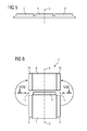
- the bobbin 2 including arranged on the bobbins 2 coils 6 - see in particular FIG. 8 - Are pivoted in this state about a respective pivot axis 11.
- the respective pivot axis 11 is determined individually for the respective bobbin 2. Although the pivot axes 11 run - see in particular the FIG. 6 and 7 - For all bobbin 2 in the circuit board 4. The respective pivot axis 11, however, relative to the respective bobbin 2, in the region of the respective bobbin second tangential to the central axes 3, 9. In FIG. 7 is - purely by way of example - for each of the bobbin 2, the respective pivot axis 11 located.
- the coil carriers 2 are radially spaced from the central axis 9 of the stator 7. Furthermore, they are arranged to be distributed around the central axis 9 of the stator 7 around the central axis 9 of the stator 7 around the central axis 9 of the stator 7, as viewed tangentially around the central axis 9 of the stator 7, similarly to the previous arrangement.
- the coil carrier 2 are arranged after pivoting on stator teeth 10 usually on a cylinder jacket about the central axis 9 of the stator 7 around. Due to the position of the pivot axes 11, the circuit carrier 4 is still arranged after the pivoting of the bobbin 2 on the stator teeth 10 at one axial end of the bobbin 2.
- auxiliary element 1 is positioned with the arranged on the auxiliary element 1 bobbins 2 and arranged on the auxiliary element 1 circuit carrier 4 only after the winding of the bobbin 2 such that the central axis 3 of the auxiliary element 1 is aligned with the central axis 9 of the stator 7 , Alternatively, it is possible that the auxiliary element 1 is already positioned accordingly before the winding of the bobbin 2.
- each a conductor wire 5 is wound so that the wound on the bobbin 2 conductor wire 5 a Coil 6 of the stator winding of the stator 7 forms.
- the technology is used for each phase a to c of the respective conductor wire 5a to 5c via the circuit substrate 4 respectively from bobbin 2 to bobbin 2 of the respective phase a to c performed. A connection of conductor ends of the conductor wires 5a to 5c in the circuit substrate 4 is no longer necessary.
- the bobbin 2 are pivoted to pivot on the stator teeth 10 by 180 ° about the respective pivot axis 11.
- the pivot angle is smaller than 180 °.
- the pivot angle is in accordance with an embodiment of the auxiliary element 1 FIG. 4 between 90 ° and 180 °.
- it can be at 150 °, 135 ° or 120 °.
- the swing angle is 90 °. This value should preferably not be undershot.
- the conductor wires 5a to 5c of the phases a to c are preferably performed without crossing.
- the conductor wires 5a to 5c of the phases a to c in the circuit substrate 4 from phase a to c to phase a to c are guided radially offset.
- One phase for example, the phase a
- another phase for example, the phase b
- another phase for example, the phase c
- the axially offset guide - can in particular the circuit substrate 4 per phase a to c according to FIG. 11 each have a sub-carrier 12a to 12c.
- the partial carrier 12a- is arranged on the auxiliary element 1 in the context of the production of the stator winding.
- the bobbin 2a of the corresponding phase a are wound.
- the next sub-carrier 12b is placed on the sub-carrier 12b, and the bobbin 2b of the next phase b are wound.
- the next subcarrier 12c is placed on the subcarrier 12b, and the bobbin carriers 2c of the next phase c are wound.
- the partial carriers 12a to 12c are stacked in the direction of the central axis 9 of the stator 7, as viewed.
- the coil carrier 2 there is no direct connection of the coil carrier 2 to the circuit carrier 4 before winding the coil carrier 2 with the conductor wires 5.
- the coil carrier 2 it is possible for the coil carrier 2 to move according to FIG. 12 each having a hinge 13.
- the bobbin 2 are connected via the respective hinge 13 in each case with the circuit carrier 4.
- the finished stator winding it is also true for the finished stator winding, so when the bobbin 2 are swung onto the stator teeth 10.
- the respective first coil carrier flange 14 faces the connection structure 8.
- the respective second coil carrier flange 15 faces away from the connection structure 8.
- the respective second Spulen39flansch 15 facing the auxiliary element 1, the respective first Spulenziflansch 14 from Auxiliary element 1 turned away.
- the Spulenryflansche 14, 15 define a winding portion 16 of the respective bobbin 2.
- the second Spulenaboflansch 15 has according to the FIGS. 13 and 14 an insertion groove 17 and a Ausgarnut 18.
- the respective conductor wire 5 is inserted into the winding region 16 of the respective bobbin 2 in the production of the stator winding before winding the respective bobbin 2.
- About the Austechnologynut 18 of the respective conductor wire 5 is performed after the winding of the respective bobbin 2 from the winding region 16 of the respective bobbin 2.
- At least the insertion groove 17 has - based on a main extension direction of the respective bobbin 2 - according to the FIGS. 13 and 14 a not completely straight course.
- the insertion groove 17 extends obliquely to the main extension direction.
- the insertion groove 17 has at least two sections, wherein at least one of the sections is not parallel to the main extension direction of the respective coil carrier 2. In the state swiveled onto the stator teeth 10, the insertion grooves 17 thereby do not extend purely axially to the central axis 9 of the stator 7, but have a tangential component at least in one section.
- the present invention is preferably used in conjunction with a stator 7 designed as a star yoke package.
- the star is formed by the connection structure 8 and the stator teeth 10 protruding radially outward from the connection structure 8.
- FIG. 15 after the pivoting of the coil carrier 2 provided with the coils 6 on the stator teeth 10 axially to the central axis 9 of the stator 7, a stator yoke 19 is pushed onto the stator teeth 10.
- a Sliding direction x is thus directed parallel to the central axis 9 of the stator 7.
- the coil carrier 2 is fixed captive, on the other hand, thereby completing the magnetic inference.
- the present invention has many advantages.
- it is possible to wind the coils 6 per phase a to c by means of a respective continuous conductor wire 5a to 5c. Due to the course of the Ein Industriesnuten 17, it can not happen that upon pivoting of the bobbin 2 on the stator teeth 10 of the conductor wire 5 comes to rest directly on the turns of the respective coil 6. As a result, compliance with clearance and creepage distances is improved in particular.
- 1 coil support 2 are arranged on an auxiliary element, so that they are radially spaced from a central axis 3 of the auxiliary element 1 and are arranged distributed tangentially thereto evenly.
- a circuit carrier 4 is arranged on the auxiliary element 1.
- conductor wires 5a to 5c are wound on coil carriers 2a to 2c assigned to phases a to c.
- the conductor wires 5a to 5c wound on the coil carriers 2a to 2c thereby form coils 6 of the stator winding.
- the lead wires 5a to 5c are passed after winding each of a bobbin 2a to 2c on the circuit substrate 4 to each next to be wound bobbin 2a to 2c of the respective phase a to c.
- the auxiliary element 1 is arranged relative to a stator 7 such that the central axis 3 of the auxiliary element 1 is aligned with the central axis 9 of the stator 7.
- the stator 7 has a number of stator teeth 10 which, starting from a radial distance r 'from a central axis 9 of the stator 7 around this circumferential connecting structure 8, protrude radially outward.
- the coil carriers 2 provided with the coils 6 are pivoted about a respective pivot axis 11 extending tangentially to the central axes 3, 9 in the region of the circuit carrier 4. This will be the ones with the coils 6 provided coil carrier 2 is pivoted from radially outside to one of the stator teeth 10.
Landscapes
- Engineering & Computer Science (AREA)
- Power Engineering (AREA)
- Manufacturing & Machinery (AREA)
- Manufacture Of Motors, Generators (AREA)
- Windings For Motors And Generators (AREA)
- Insulation, Fastening Of Motor, Generator Windings (AREA)
Priority Applications (5)
| Application Number | Priority Date | Filing Date | Title |
|---|---|---|---|
| EP13176073.8A EP2824811A1 (fr) | 2013-07-11 | 2013-07-11 | Enroulement de stator traversant enroulé sur un support de bobine |
| EP13758784.6A EP2994980B1 (fr) | 2013-07-11 | 2013-08-27 | Enroulement de stator traversant enroulé sur un support de bobine |
| PCT/EP2013/067666 WO2015003757A1 (fr) | 2013-07-11 | 2013-08-27 | Enroulement statorique continu bobiné sur des supports de bobines |
| CN201380077765.9A CN105340159B (zh) | 2013-07-11 | 2013-08-27 | 连续的、缠绕在线轴上的定子绕组 |
| US14/903,894 US9450465B2 (en) | 2013-07-11 | 2013-08-27 | Continuous stator winding wound on bobbins |
Applications Claiming Priority (1)
| Application Number | Priority Date | Filing Date | Title |
|---|---|---|---|
| EP13176073.8A EP2824811A1 (fr) | 2013-07-11 | 2013-07-11 | Enroulement de stator traversant enroulé sur un support de bobine |
Publications (1)
| Publication Number | Publication Date |
|---|---|
| EP2824811A1 true EP2824811A1 (fr) | 2015-01-14 |
Family
ID=48783008
Family Applications (2)
| Application Number | Title | Priority Date | Filing Date |
|---|---|---|---|
| EP13176073.8A Withdrawn EP2824811A1 (fr) | 2013-07-11 | 2013-07-11 | Enroulement de stator traversant enroulé sur un support de bobine |
| EP13758784.6A Active EP2994980B1 (fr) | 2013-07-11 | 2013-08-27 | Enroulement de stator traversant enroulé sur un support de bobine |
Family Applications After (1)
| Application Number | Title | Priority Date | Filing Date |
|---|---|---|---|
| EP13758784.6A Active EP2994980B1 (fr) | 2013-07-11 | 2013-08-27 | Enroulement de stator traversant enroulé sur un support de bobine |
Country Status (4)
| Country | Link |
|---|---|
| US (1) | US9450465B2 (fr) |
| EP (2) | EP2824811A1 (fr) |
| CN (1) | CN105340159B (fr) |
| WO (1) | WO2015003757A1 (fr) |
Cited By (1)
| Publication number | Priority date | Publication date | Assignee | Title |
|---|---|---|---|---|
| WO2017038707A1 (fr) * | 2015-08-28 | 2017-03-09 | アイシン・エィ・ダブリュ株式会社 | Procédé de fabrication de stator, et procédé de fabrication de machine électrique tournante |
Families Citing this family (4)
| Publication number | Priority date | Publication date | Assignee | Title |
|---|---|---|---|---|
| EP3203609A1 (fr) | 2016-02-04 | 2017-08-09 | Siemens Aktiengesellschaft | Rotor pour une machine synchrone excitee par un aimant permanent, tige d'espace interpolaire pour un tel rotor et procede de fabrication d'un tel rotor |
| DE102017200314A1 (de) * | 2017-01-11 | 2018-07-12 | Robert Bosch Gmbh | Elektrische Maschine mit einem Stator und ein Verfahren für den Stator |
| GB2571553B (en) | 2018-03-01 | 2020-07-01 | Dyson Technology Ltd | Brushless motor |
| EP4236040A4 (fr) * | 2020-10-23 | 2025-01-01 | Minebea Mitsumi Inc. | Moteur |
Citations (5)
| Publication number | Priority date | Publication date | Assignee | Title |
|---|---|---|---|---|
| EP1783880A2 (fr) * | 2005-11-04 | 2007-05-09 | Denso Corporation | Moteur électrique et pompe à carburant avec celui-ci |
| EP2059991A1 (fr) * | 2006-09-06 | 2009-05-20 | Wilo Ag | Dispositif porte-bobine |
| US20090230793A1 (en) * | 2008-03-12 | 2009-09-17 | Hirao Yasuyuki | Stator mounting method |
| DE102009023231A1 (de) * | 2009-05-29 | 2010-12-02 | Brose Fahrzeugteile GmbH & Co. Kommanditgesellschaft, Würzburg | Stator für einen Elektromotor |
| EP2549622A1 (fr) | 2011-07-22 | 2013-01-23 | Siemens Aktiengesellschaft | Machine électrique dotée d'un élément actif à dents évasées |
Family Cites Families (16)
| Publication number | Priority date | Publication date | Assignee | Title |
|---|---|---|---|---|
| DE10231596A1 (de) | 2002-07-12 | 2004-01-22 | Robert Bosch Gmbh | Elektrische Maschine |
| US7692356B2 (en) | 2003-06-20 | 2010-04-06 | Siemens Aktiengesellschaft | Electric machine with a circuit support |
| EP1578003A1 (fr) | 2004-03-08 | 2005-09-21 | Siemens Aktiengesellschaft | Machine électrique avec un dispositif pour connecter les enroulements |
| DE102005016855A1 (de) | 2005-04-12 | 2006-10-19 | Siemens Ag | Schnittstellenmodul zur Anordnung in oder an einem Motor |
| DE102005032720B4 (de) | 2005-07-13 | 2007-04-05 | Siemens Ag | Schnittstellenmodulvorrichtung für eine elektrische Maschine zur Lebensdauerberechnung eines Lagers |
| JP4797728B2 (ja) * | 2006-03-22 | 2011-10-19 | トヨタ自動車株式会社 | 回転電機の固定子、固定子に用いられる部品および回転電機の固定子の製造方法 |
| CN101694954B (zh) * | 2006-07-04 | 2012-07-25 | 本田技研工业株式会社 | 电动机的定子结构 |
| DE102007013049A1 (de) | 2007-03-19 | 2008-09-25 | Siemens Ag | Verfahren zum Montieren eines Winkelmessgeräts an einem elektrischen Motor |
| DE102007021321A1 (de) | 2007-05-07 | 2008-11-13 | Siemens Ag | Stator mit Stromschienen zum Verschalten der Spulen und entsprechendes Verfahren |
| JP2009033836A (ja) * | 2007-07-26 | 2009-02-12 | Aisin Seiki Co Ltd | モータのヒュージング構造 |
| JP5094505B2 (ja) * | 2008-03-28 | 2012-12-12 | 三洋電機株式会社 | 電動機 |
| EP2151908B1 (fr) | 2008-08-04 | 2010-10-06 | Siemens Aktiengesellschaft | Machine dynamoélectrique dotée d'un boîtier de connexion en plusieurs parties |
| JP5083257B2 (ja) * | 2009-03-23 | 2012-11-28 | アイシン・エィ・ダブリュ株式会社 | ステータの製造装置 |
| JP5537964B2 (ja) * | 2010-01-19 | 2014-07-02 | 株式会社日立製作所 | 回転電機 |
| EP2458715B1 (fr) * | 2010-11-05 | 2014-01-08 | LG Innotek Co., Ltd. | Barre omnibus de moteur EPS |
| JP2012228007A (ja) * | 2011-04-15 | 2012-11-15 | Asmo Co Ltd | バスバー装置、ステータ、モータ及びステータの製造方法 |
-
2013
- 2013-07-11 EP EP13176073.8A patent/EP2824811A1/fr not_active Withdrawn
- 2013-08-27 CN CN201380077765.9A patent/CN105340159B/zh active Active
- 2013-08-27 EP EP13758784.6A patent/EP2994980B1/fr active Active
- 2013-08-27 WO PCT/EP2013/067666 patent/WO2015003757A1/fr not_active Ceased
- 2013-08-27 US US14/903,894 patent/US9450465B2/en active Active
Patent Citations (5)
| Publication number | Priority date | Publication date | Assignee | Title |
|---|---|---|---|---|
| EP1783880A2 (fr) * | 2005-11-04 | 2007-05-09 | Denso Corporation | Moteur électrique et pompe à carburant avec celui-ci |
| EP2059991A1 (fr) * | 2006-09-06 | 2009-05-20 | Wilo Ag | Dispositif porte-bobine |
| US20090230793A1 (en) * | 2008-03-12 | 2009-09-17 | Hirao Yasuyuki | Stator mounting method |
| DE102009023231A1 (de) * | 2009-05-29 | 2010-12-02 | Brose Fahrzeugteile GmbH & Co. Kommanditgesellschaft, Würzburg | Stator für einen Elektromotor |
| EP2549622A1 (fr) | 2011-07-22 | 2013-01-23 | Siemens Aktiengesellschaft | Machine électrique dotée d'un élément actif à dents évasées |
Cited By (3)
| Publication number | Priority date | Publication date | Assignee | Title |
|---|---|---|---|---|
| WO2017038707A1 (fr) * | 2015-08-28 | 2017-03-09 | アイシン・エィ・ダブリュ株式会社 | Procédé de fabrication de stator, et procédé de fabrication de machine électrique tournante |
| JPWO2017038707A1 (ja) * | 2015-08-28 | 2018-02-22 | アイシン・エィ・ダブリュ株式会社 | ステータの製造方法および回転電機の製造方法 |
| CN107925320A (zh) * | 2015-08-28 | 2018-04-17 | 爱信艾达株式会社 | 定子的制造方法和旋转电机的制造方法 |
Also Published As
| Publication number | Publication date |
|---|---|
| EP2994980B1 (fr) | 2017-11-08 |
| CN105340159A (zh) | 2016-02-17 |
| EP2994980A1 (fr) | 2016-03-16 |
| US9450465B2 (en) | 2016-09-20 |
| CN105340159B (zh) | 2017-11-24 |
| US20160156242A1 (en) | 2016-06-02 |
| WO2015003757A1 (fr) | 2015-01-15 |
Similar Documents
| Publication | Publication Date | Title |
|---|---|---|
| EP2148410A1 (fr) | Machine électrique dotée d'une construction d'enroulement à gradins | |
| DE102014208909A1 (de) | Rotierende elektrische Vorrichtung | |
| EP3534498B1 (fr) | Procédé et dispositif de fabrication d'un stator doté d'un enroulement à bobines à air réduites | |
| EP2994980B1 (fr) | Enroulement de stator traversant enroulé sur un support de bobine | |
| DE102019117966A1 (de) | Verfahren zur Herstellung einer Spulenwicklung zum Einlegen in radial offene Nuten von Statoren oder Rotoren von Elektromaschinen | |
| DE112015005324T5 (de) | Statormontageverfahren und Statormontagevorrichtung | |
| DE102015225586A1 (de) | Spulenkörper für eine elektrische Spule | |
| EP3624314A1 (fr) | Insertion d'enroulements dans un paquet de tôles de stator | |
| DE102015211836A1 (de) | Verfahren zum Bewickeln eines Stators, sowie ein Stator und eine elektrische Maschine beinhaltend einen solchen Stator | |
| DE102014217289A1 (de) | Wicklungsanordnung und Verfahren zur Herstellung einer Wicklungsanordnung | |
| DE102016223003A1 (de) | Stator für eine elektrische Maschine sowie eine elektrische Maschine mit solch einem Stator | |
| DE102018206003A1 (de) | Vorrichtung und Verfahren zur Ausrichtung einer Hairpinwicklung | |
| DE102010043976A1 (de) | Komponente zum Herstellen einer Maschinenkomponente für eine elektrische Maschine | |
| DE102012209442A1 (de) | Elektrische Maschine mit radial versetzt angeordneten Teilwicklungsköpfen | |
| DE102019203272A1 (de) | Elektronisch kommutierter Motor | |
| DE102015208414A1 (de) | Wicklungszahn einer elektrischen Maschine | |
| EP0809345B1 (fr) | Méthode de fabrication d'un rotor pour indicateur de position angulaire avec transformateur rotatif et corps de bobine à utiliser dans ce procédé | |
| DE10237096A1 (de) | Wickelverfahren und Aufbau für Statorwicklungen | |
| EP2790298B1 (fr) | Stator d'un moteur électrique | |
| DE102013223727B4 (de) | Elektromotor mit einem segmentierten Stator | |
| EP3429063A1 (fr) | Enroulement monocouche de support pour des machines électriques | |
| DE102016004903A1 (de) | Stator mit Lackzufuhrdurchgang und Motor | |
| EP2858212B1 (fr) | Procédé d'enroulement pour un enroulement de stator et stator correspondant | |
| DE102014213435A1 (de) | Verfahren zum Herstellen einer elektrischen Maschine mit Formspulen sowie elektrische Maschine und Herstellungswerkzeug | |
| EP4029121A1 (fr) | Unité d'enroulement en forme de bande pour un enroulement de stator et procédé de fabrication d'une unité d'enroulement en forme de bande |
Legal Events
| Date | Code | Title | Description |
|---|---|---|---|
| 17P | Request for examination filed |
Effective date: 20130711 |
|
| AK | Designated contracting states |
Kind code of ref document: A1 Designated state(s): AL AT BE BG CH CY CZ DE DK EE ES FI FR GB GR HR HU IE IS IT LI LT LU LV MC MK MT NL NO PL PT RO RS SE SI SK SM TR |
|
| AX | Request for extension of the european patent |
Extension state: BA ME |
|
| PUAI | Public reference made under article 153(3) epc to a published international application that has entered the european phase |
Free format text: ORIGINAL CODE: 0009012 |
|
| STAA | Information on the status of an ep patent application or granted ep patent |
Free format text: STATUS: THE APPLICATION IS DEEMED TO BE WITHDRAWN |
|
| 18D | Application deemed to be withdrawn |
Effective date: 20150715 |