EP2824842A2 - Verfahren und Anordnung zur Durchführung von Intrarahmenverschachtelung - Google Patents
Verfahren und Anordnung zur Durchführung von Intrarahmenverschachtelung Download PDFInfo
- Publication number
- EP2824842A2 EP2824842A2 EP20140172435 EP14172435A EP2824842A2 EP 2824842 A2 EP2824842 A2 EP 2824842A2 EP 20140172435 EP20140172435 EP 20140172435 EP 14172435 A EP14172435 A EP 14172435A EP 2824842 A2 EP2824842 A2 EP 2824842A2
- Authority
- EP
- European Patent Office
- Prior art keywords
- information symbols
- order
- component streams
- stream
- spreading codes
- Prior art date
- Legal status (The legal status is an assumption and is not a legal conclusion. Google has not performed a legal analysis and makes no representation as to the accuracy of the status listed.)
- Withdrawn
Links
- 238000000034 method Methods 0.000 title claims abstract description 16
- 238000013507 mapping Methods 0.000 claims abstract description 18
- 230000005540 biological transmission Effects 0.000 claims abstract description 6
- 238000000926 separation method Methods 0.000 claims description 7
- 230000011218 segmentation Effects 0.000 description 4
- 238000010586 diagram Methods 0.000 description 2
- 238000005516 engineering process Methods 0.000 description 2
- 230000004048 modification Effects 0.000 description 2
- 238000012986 modification Methods 0.000 description 2
- 238000010276 construction Methods 0.000 description 1
Images



Classifications
-
- H—ELECTRICITY
- H03—ELECTRONIC CIRCUITRY
- H03M—CODING; DECODING; CODE CONVERSION IN GENERAL
- H03M13/00—Coding, decoding or code conversion, for error detection or error correction; Coding theory basic assumptions; Coding bounds; Error probability evaluation methods; Channel models; Simulation or testing of codes
- H03M13/27—Coding, decoding or code conversion, for error detection or error correction; Coding theory basic assumptions; Coding bounds; Error probability evaluation methods; Channel models; Simulation or testing of codes using interleaving techniques
-
- H—ELECTRICITY
- H04—ELECTRIC COMMUNICATION TECHNIQUE
- H04L—TRANSMISSION OF DIGITAL INFORMATION, e.g. TELEGRAPHIC COMMUNICATION
- H04L1/00—Arrangements for detecting or preventing errors in the information received
- H04L1/004—Arrangements for detecting or preventing errors in the information received by using forward error control
- H04L1/0056—Systems characterized by the type of code used
- H04L1/0071—Use of interleaving
-
- H—ELECTRICITY
- H03—ELECTRONIC CIRCUITRY
- H03M—CODING; DECODING; CODE CONVERSION IN GENERAL
- H03M13/00—Coding, decoding or code conversion, for error detection or error correction; Coding theory basic assumptions; Coding bounds; Error probability evaluation methods; Channel models; Simulation or testing of codes
- H03M13/27—Coding, decoding or code conversion, for error detection or error correction; Coding theory basic assumptions; Coding bounds; Error probability evaluation methods; Channel models; Simulation or testing of codes using interleaving techniques
- H03M13/2703—Coding, decoding or code conversion, for error detection or error correction; Coding theory basic assumptions; Coding bounds; Error probability evaluation methods; Channel models; Simulation or testing of codes using interleaving techniques the interleaver involving at least two directions
- H03M13/271—Row-column interleaver with permutations, e.g. block interleaving with inter-row, inter-column, intra-row or intra-column permutations
-
- H—ELECTRICITY
- H03—ELECTRONIC CIRCUITRY
- H03M—CODING; DECODING; CODE CONVERSION IN GENERAL
- H03M13/00—Coding, decoding or code conversion, for error detection or error correction; Coding theory basic assumptions; Coding bounds; Error probability evaluation methods; Channel models; Simulation or testing of codes
- H03M13/27—Coding, decoding or code conversion, for error detection or error correction; Coding theory basic assumptions; Coding bounds; Error probability evaluation methods; Channel models; Simulation or testing of codes using interleaving techniques
- H03M13/2757—Interleaver with an interleaving rule not provided for in the subgroups H03M13/2703 - H03M13/2753
Definitions
- the invention concerns generally the technology of interleaving transmission symbols in a radio transceiver in time domain. Especially the invention concerns the technology of implementing intra-frame interleaving in multicode transceivers of the proposed UTRA (Universal Terrestrial Radio Access) system.
- UTRA Universal Terrestrial Radio Access
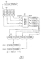
- Fig. 1 illustrates the transport channel multiplexing structure for uplink as defined in said document.
- CRC attachment 101 CRC attachment 101
- transport block concatenation and code block segmentation 102 channel coding 103
- radio frame equalisation 104 first interleaving 105
- radio frame segmentation 106 radio frame segmentation 106 and rate matching 107.
- Several entities of the above-described kind may be coupled to the inputs of a transport channel multiplexing stage 108, the output of which is further coupled to the serial connection of physical channel segmentation 109, second interleaving 110 and physical channel mapping 111.
- the aim of the second interleaving 110 is to permutate the bits in time domain so that bits that originally were close to each other in the bit stream to be transmitted are separated from each other in the time domain for the duration of their travel over the radio interface. This way a short interval of extremely bad interference conditions at the radio interface should not cause any bursts of several consecutive erroneous bits in the received and decoded bit stream.
- the second interleaving 110 takes place in intra-frame manner meaning that the data entity subjected to interleaving is one radio frame.
- Fig. 2 illustrates the operation of the second interleaving stage.
- the bits that come as an input stream 201 to the interleaver are written into a bit array 202 which has a certain number of rows and a certain number of columns.
- the numbers shown in the input stream and the bit array are simply the serial numbers of the bits in the radio frame.
- the number of columns is shown to be 32, with column numbers ranging from 0 to 31.
- the columns are fed into an intercolumn permutator 203 which rearranges them into a different order.
- the 0th column remains 0th
- the 17th column comes 1st
- the 14th column comes 30th
- the 31th column remains 31th after the intercolumn permutator 203.
- the bits are read from the permutated columns to the output of the second interleaving stage column by column.
- the bit stream 204 with the serial number of certain bits is shown as the output of the second interleaving stage.
- the TDD or Time Division Duplex mode with its possibility of simultaneously using several spreading codes brings about some complications to the presented arrangement.
- the bit stream 204 is transmitted by using that spreading code.
- the transmitting device has at least two spreading codes at its disposal, and it transmits by using these parallel spreading codes simultaneously during a single time slot.
- the presently defined physical channel mapping arrangement is such that the parallel spreading codes are filled one at a time with bits taken from the bit stream 204. This may lead to the situation shown at the bottom of Fig. 2 where, during a certain time slot, e.g. bits 0 and 14, bits 32 and 46 and so on of a certain frame are transmitted simultaneously.
- the number of parallel spreading codes may vary between 2 and 9.
- the arrangement according to Fig. 2 has the drawback of in the multicode situation canceling much of the advantages usually obtained through the second interleaving, because certain bits that are near to each other in the frame are practically not separated at all in the time domain at the radio interface.
- the nature of the interference occurring in UTRA systems is such that it may occur e.g. that a part of a time slot either from the very beginning or from the very end of the time slot gets erased due to interference, especially inter-operator interference.
- the result of such an erasure, taken the arrangement of Fig. 2 is a burst of errors very close to each other in a received frame.
- the objects of the invention are achived by modifying the order in which the bits are mapped into the spreading codes after the second interleaving stage.
- the method according to the invention is meant for interleaving a stream of data consisting of digital information symbols prior to transmission over a radio interface. It comprises the steps of
- It is characterized in that it comprises the step of reversing the order of information symbols in at least one component stream prior to mapping it into a spreading code.
- the invention also applies to a transmitter arrangement which comprises
- radio device comprises means for reversing the order of information symbols in at least one component stream prior to mapping it into a spreading code.
- the present invention is based on a finding that the mapping of bits into the parallel spreading codes has a key role in maintaining the separation of bits in the time domain.
- An advantageous way to eliminate the drawbacks of the existing arrangements is to modify the order in which the bits are mapped at least to a part of the spreading codes.
- the invention requires only a minor change in the existing proposed arrangements, and yet it provides a significant relief to the problem of maintaining sufficient separation in time domain between bits that are close to each other in the frame.
- Fig. 3 The upper part of Fig. 3 is similar to that of Fig. 2 :
- the bits that come as an input stream 201 to a second interleaver are written into a bit array 202 which has a certain number of rows and a certain number of columns.
- the number of columns is again 32, with column numbers ranging from 0 to 31.
- the columns are fed into an intercolumn permutator 203 which rearranges them into a different order.
- the present invention does not change the operation of the intercolumn permutator, so the 0th column remains 0th, the 17th column comes 1st, the 14th column comes 30th and the 31th column remains 31th after the intercolumn permutator 203 just as in the prior art arrangement of Fig. 2 .
- the invention pertains to the order in which the bits are read from the permutated columns to the output of the second interleaving stage, which is also the input of the physical channel mapping stage.
- the bit stream 204 with the serial number of certain bits is shown as the known output form of the second interleaving stage.
- the bits are mapped therefrom to the parallel spreading codes of which there are two in Fig. 3 , the order of bits in the component bit stream that goes into the second spreading code is reversed.
- Fig. 3 The principle shown in Fig. 3 is easily generalized to the case of N parallel spreading codes, where N is a positive integer greater than 2, by stating that the bit order in every second component bit stream is reversed before mapping that component bit stream into the corresponding spreading code.
- the invention does not limit the choice of the actual physical step in which the inverting of bit order is made for every second component bit stream.
- the system specifications of communications systems like the UTRA do not usually specify any particular hardware implementation for performing the standardized operations, but these are left into the discretion of transceiver designers.
- One advantageous way to perform the reversing is to integrate it into the step in which the bits are read from the bit array 202 after column permutation: the step of permutating columns does not mean anything else than correctly selecting the order in which bits are read from the memory locations where they are stored when they are said to be in the bit array.
- the transceiver may reorganize this reading order that in addition to the permutated order of columns, it takes into account the fact that those columns that go to the bit streams destined to be reversed are read in an inverted order and from bottom to top in the array representation.
- Fig. 4 illustrates a method according to an advantageous embodiment of the invention in the form of a flow diagram.
- the steps shown in Fig. 4 belong functionally to the second interleaving stage 110 shown in Fig. 1 .
- Step 401 corresponds to writing the input bits into a bit array
- step 402 corresponds to permutating the columns.
- the transceiver checks the number of spreading codes it has at its disposal for transmitting this particular frame. If the number of codes is only one, the permutated columns are output in the known order so that they can be correctly mapped into the spreading code at step 406. If, however, there is a positive finding at step 403, component streams are (at least conceptually) composed at step 404 and in every second one of these the bit order is reversed at step 405.
- Fig. 5 illustrates the structure of a mobile terminal or base station where the parts from the CRC attacher 101 to the physical channel segmentator 109 may be similar as in known devices that conform to the TS 25.212 document mentioned in the description of prior art.
- the second interleaver 510 and the physical channel mapper 511 together are arranged to implement the method illustrated in Fig. 4 ; the physical implementation of the method is straightforward and within the capabilities of a person skilled in the art on the basis of the above-given instructions.
Landscapes
- Engineering & Computer Science (AREA)
- Physics & Mathematics (AREA)
- Probability & Statistics with Applications (AREA)
- Theoretical Computer Science (AREA)
- Computer Networks & Wireless Communication (AREA)
- Signal Processing (AREA)
- Error Detection And Correction (AREA)
- Detection And Prevention Of Errors In Transmission (AREA)
- Transmission Systems Not Characterized By The Medium Used For Transmission (AREA)
- Television Signal Processing For Recording (AREA)
- Holo Graphy (AREA)
- Reverberation, Karaoke And Other Acoustics (AREA)
Applications Claiming Priority (3)
| Application Number | Priority Date | Filing Date | Title |
|---|---|---|---|
| FI992561A FI114766B (fi) | 1999-11-30 | 1999-11-30 | Menetelmä ja järjestelmä kehyksen sisäisen lomituksen toteuttamiseksi |
| EP00983366A EP1247344B1 (de) | 1999-11-30 | 2000-11-29 | Verfahren und anordnung zur durchführung von intrarahmenverschachtelung |
| EP08159169.5A EP1968199B1 (de) | 1999-11-30 | 2000-11-29 | Verfahren und Vorrichtung zur Durchführung von Intrarahmenverschachtelung |
Related Parent Applications (3)
| Application Number | Title | Priority Date | Filing Date |
|---|---|---|---|
| EP08159169.5A Division-Into EP1968199B1 (de) | 1999-11-30 | 2000-11-29 | Verfahren und Vorrichtung zur Durchführung von Intrarahmenverschachtelung |
| EP08159169.5A Division EP1968199B1 (de) | 1999-11-30 | 2000-11-29 | Verfahren und Vorrichtung zur Durchführung von Intrarahmenverschachtelung |
| EP00983366A Division EP1247344B1 (de) | 1999-11-30 | 2000-11-29 | Verfahren und anordnung zur durchführung von intrarahmenverschachtelung |
Publications (2)
| Publication Number | Publication Date |
|---|---|
| EP2824842A2 true EP2824842A2 (de) | 2015-01-14 |
| EP2824842A3 EP2824842A3 (de) | 2015-04-08 |
Family
ID=8555666
Family Applications (3)
| Application Number | Title | Priority Date | Filing Date |
|---|---|---|---|
| EP00983366A Expired - Lifetime EP1247344B1 (de) | 1999-11-30 | 2000-11-29 | Verfahren und anordnung zur durchführung von intrarahmenverschachtelung |
| EP20140172435 Withdrawn EP2824842A3 (de) | 1999-11-30 | 2000-11-29 | Verfahren und Anordnung zur Durchführung von Intrarahmenverschachtelung |
| EP08159169.5A Expired - Lifetime EP1968199B1 (de) | 1999-11-30 | 2000-11-29 | Verfahren und Vorrichtung zur Durchführung von Intrarahmenverschachtelung |
Family Applications Before (1)
| Application Number | Title | Priority Date | Filing Date |
|---|---|---|---|
| EP00983366A Expired - Lifetime EP1247344B1 (de) | 1999-11-30 | 2000-11-29 | Verfahren und anordnung zur durchführung von intrarahmenverschachtelung |
Family Applications After (1)
| Application Number | Title | Priority Date | Filing Date |
|---|---|---|---|
| EP08159169.5A Expired - Lifetime EP1968199B1 (de) | 1999-11-30 | 2000-11-29 | Verfahren und Vorrichtung zur Durchführung von Intrarahmenverschachtelung |
Country Status (15)
| Country | Link |
|---|---|
| US (1) | US6904077B2 (de) |
| EP (3) | EP1247344B1 (de) |
| JP (1) | JP3331209B2 (de) |
| KR (1) | KR100680120B1 (de) |
| CN (1) | CN1402910B (de) |
| AT (1) | ATE435528T1 (de) |
| AU (1) | AU773939B2 (de) |
| BR (1) | BR0014627A (de) |
| CA (1) | CA2392707C (de) |
| DE (1) | DE60042495D1 (de) |
| ES (2) | ES2500492T3 (de) |
| FI (1) | FI114766B (de) |
| MX (1) | MXPA02005332A (de) |
| PT (1) | PT1247344E (de) |
| WO (1) | WO2001041314A1 (de) |
Families Citing this family (18)
| Publication number | Priority date | Publication date | Assignee | Title |
|---|---|---|---|---|
| JP2001285077A (ja) * | 2000-03-31 | 2001-10-12 | Mitsubishi Electric Corp | 通信装置および通信方法 |
| AU2002212563A1 (en) * | 2000-08-25 | 2002-03-04 | T. Kiran | A technique for reducing processing power in 3g systems |
| GB0120535D0 (en) * | 2001-08-23 | 2001-10-17 | Roke Manor Research | Space-time interleaving transmit diversity |
| US7292552B2 (en) | 2002-03-14 | 2007-11-06 | Qualcomm Incorporated | Method and apparatus for reducing interference in a wireless communication system |
| US7035284B2 (en) | 2002-03-14 | 2006-04-25 | Qualcomm Incorporated | Method and apparatus for reducing inter-channel interference in a wireless communication system employing a non-periodic interleaver |
| GB2387515A (en) * | 2002-04-08 | 2003-10-15 | Ipwireless Inc | Mapping bits to at least two channels using two interleavers, one for systematic bits, and the other for parity bits |
| US6919829B2 (en) † | 2003-06-20 | 2005-07-19 | Nokia Corporation | Bit swapping for different interleaving depths |
| CN1655488B (zh) * | 2004-02-11 | 2010-12-15 | 诺基亚西门子通信系统技术(北京)有限公司 | 一种无线通信系统中增长交织时间的方法 |
| JP2005318291A (ja) * | 2004-04-28 | 2005-11-10 | Yamaha Corp | データ伝送方法、サーバ装置、データ受信装置、および、データ伝送システム。 |
| US7570698B2 (en) * | 2004-11-16 | 2009-08-04 | Intel Corporation | Multiple output multicarrier transmitter and methods for spatial interleaving a plurality of spatial streams |
| US7542410B2 (en) * | 2004-12-06 | 2009-06-02 | Intel Corporation | Interleaver and associated methods |
| US20070044126A1 (en) * | 2005-08-18 | 2007-02-22 | Rockwell Collins, Inc. | Wireless video entertainment system |
| US8769365B2 (en) | 2010-10-08 | 2014-07-01 | Blackberry Limited | Message rearrangement for improved wireless code performance |
| CA2814069C (en) * | 2010-10-08 | 2016-07-19 | Research In Motion Limited | Message rearrangement for improved code performance |
| US8850276B2 (en) * | 2011-09-22 | 2014-09-30 | Lsi Corporation | Systems and methods for efficient data shuffling in a data processing system |
| US9043667B2 (en) | 2011-11-04 | 2015-05-26 | Blackberry Limited | Method and system for up-link HARQ-ACK and CSI transmission |
| WO2013169330A1 (en) | 2012-05-11 | 2013-11-14 | Research In Motion Limited | Method and system for uplink harq and csi multiplexing for carrier aggregation |
| KR102383060B1 (ko) * | 2021-02-09 | 2022-04-08 | 어메이징썬 주식회사 | 충격흡수장치가 구비되어 선 채로 체중이 지지되는 전동킥보드 |
Family Cites Families (14)
| Publication number | Priority date | Publication date | Assignee | Title |
|---|---|---|---|---|
| US4547887A (en) * | 1983-11-30 | 1985-10-15 | The United States Of America As Represented By The Secretary Of The Army | Pseudo-random convolutional interleaving |
| US5056112A (en) * | 1989-07-28 | 1991-10-08 | At&T Bell Laboratories | Interleaving in coded modulation for mobile radio |
| JP3258022B2 (ja) * | 1993-12-29 | 2002-02-18 | ゼニス、エレクトロニクス コーポレーション | 可変サイズデータ配列のためのデータ・フレーム・フォーマット |
| US5602875A (en) * | 1995-01-13 | 1997-02-11 | Motorola, Inc. | Method and apparatus for encoding and decoding information in a digtial communication system |
| US5796755A (en) * | 1995-10-10 | 1998-08-18 | Eastman Kodak Company | Error minimization in interleaved error correcting codes |
| US5996104A (en) | 1996-09-13 | 1999-11-30 | Herzberg; Hanan | System for coding system |
| US6373831B1 (en) * | 1997-03-26 | 2002-04-16 | Nortel Networks Ltd. | Systems and methods of channel coding and inverse-multiplexing for multi-carrier CDMA systems |
| US6421333B1 (en) | 1997-06-21 | 2002-07-16 | Nortel Networks Limited | Channel coding and interleaving for transmission on a multicarrier system |
| US6631491B1 (en) * | 1997-11-10 | 2003-10-07 | Ntt Mobile Communications Network, Inc. | Interleaving method, interleaving apparatus, and recording medium in which interleave pattern generating program is recorded |
| US6304581B1 (en) * | 1999-02-16 | 2001-10-16 | Motorola, Inc. | Interleaving method and apparatus for orthogonal transmit diversity and multi-carriers CDMA communication systems |
| FR2792128B1 (fr) | 1999-04-07 | 2001-09-07 | Mitsubishi Electric France | Procede et dispositif pour entrelacement de canal et multiplexage |
| CA2742096C (en) | 1999-04-13 | 2015-01-06 | Ericsson Ab | Rate matching and channel interleaving for a communications system |
| US6311306B1 (en) * | 1999-04-26 | 2001-10-30 | Motorola, Inc. | System for error control by subdividing coded information units into subsets reordering and interlacing the subsets, to produce a set of interleaved coded information units |
| US6259744B1 (en) * | 1999-06-01 | 2001-07-10 | Motorola, Inc. | Method and apparatus for mapping bits to an information burst |
-
1999
- 1999-11-30 FI FI992561A patent/FI114766B/fi not_active IP Right Cessation
-
2000
- 2000-11-28 JP JP2000361468A patent/JP3331209B2/ja not_active Expired - Fee Related
- 2000-11-29 EP EP00983366A patent/EP1247344B1/de not_active Expired - Lifetime
- 2000-11-29 MX MXPA02005332A patent/MXPA02005332A/es active IP Right Grant
- 2000-11-29 PT PT00983366T patent/PT1247344E/pt unknown
- 2000-11-29 ES ES08159169.5T patent/ES2500492T3/es not_active Expired - Lifetime
- 2000-11-29 CN CN008165033A patent/CN1402910B/zh not_active Expired - Lifetime
- 2000-11-29 ES ES00983366T patent/ES2325876T3/es not_active Expired - Lifetime
- 2000-11-29 EP EP20140172435 patent/EP2824842A3/de not_active Withdrawn
- 2000-11-29 WO PCT/FI2000/001037 patent/WO2001041314A1/en not_active Ceased
- 2000-11-29 KR KR1020027005554A patent/KR100680120B1/ko not_active Expired - Fee Related
- 2000-11-29 US US09/726,079 patent/US6904077B2/en not_active Expired - Lifetime
- 2000-11-29 AU AU20132/01A patent/AU773939B2/en not_active Ceased
- 2000-11-29 CA CA002392707A patent/CA2392707C/en not_active Expired - Fee Related
- 2000-11-29 DE DE60042495T patent/DE60042495D1/de not_active Expired - Lifetime
- 2000-11-29 BR BR0014627-7A patent/BR0014627A/pt active Search and Examination
- 2000-11-29 EP EP08159169.5A patent/EP1968199B1/de not_active Expired - Lifetime
- 2000-11-29 AT AT00983366T patent/ATE435528T1/de not_active IP Right Cessation
Non-Patent Citations (1)
| Title |
|---|
| "TS 25.212 V3.0.0", 3RD GENERATION PARTNERSHIP PROJECT (3GPP, October 1999 (1999-10-01) |
Also Published As
| Publication number | Publication date |
|---|---|
| KR20020048998A (ko) | 2002-06-24 |
| WO2001041314A1 (en) | 2001-06-07 |
| EP1247344A2 (de) | 2002-10-09 |
| ES2325876T3 (es) | 2009-09-23 |
| EP1968199B1 (de) | 2014-07-30 |
| MXPA02005332A (es) | 2002-12-06 |
| ES2500492T3 (es) | 2014-09-30 |
| CN1402910A (zh) | 2003-03-12 |
| HK1118646A1 (en) | 2009-02-13 |
| BR0014627A (pt) | 2002-06-11 |
| EP1968199A3 (de) | 2009-06-10 |
| CN1402910B (zh) | 2010-05-05 |
| WO2001041314A8 (en) | 2001-09-07 |
| EP1968199A2 (de) | 2008-09-10 |
| CA2392707A1 (en) | 2001-06-07 |
| AU2013201A (en) | 2001-06-12 |
| AU773939B2 (en) | 2004-06-10 |
| PT1247344E (pt) | 2009-07-20 |
| EP1247344B1 (de) | 2009-07-01 |
| EP2824842A3 (de) | 2015-04-08 |
| US6904077B2 (en) | 2005-06-07 |
| DE60042495D1 (de) | 2009-08-13 |
| JP2001197035A (ja) | 2001-07-19 |
| ATE435528T1 (de) | 2009-07-15 |
| FI114766B (fi) | 2004-12-15 |
| US20010053173A1 (en) | 2001-12-20 |
| JP3331209B2 (ja) | 2002-10-07 |
| CA2392707C (en) | 2008-09-09 |
| KR100680120B1 (ko) | 2007-02-07 |
| FI19992561L (fi) | 2001-05-31 |
Similar Documents
| Publication | Publication Date | Title |
|---|---|---|
| EP1968199B1 (de) | Verfahren und Vorrichtung zur Durchführung von Intrarahmenverschachtelung | |
| CN100499442C (zh) | 通信系统中发送和接收数据的设备和方法 | |
| JP3657254B2 (ja) | 符号分割多重接続移動通信システムで符号化およびレートマッチング装置および方法 | |
| EP1495569B1 (de) | Kanalzuordnung in einem drahtlosen kommunikationssystem | |
| KR100605811B1 (ko) | 고속 패킷 전송 시스템에서 디레이트 매칭 방법 및 그 장치 | |
| KR101498052B1 (ko) | 무선 이동 통신 시스템에서 데이터 정보와 제어 정보를 다중화 하는 방법 | |
| KR100494884B1 (ko) | 터보 코더에 공급될 데이터 블록을 정합시키기 위한 방법및 이에 상응하는 통신기기 | |
| CN101325739A (zh) | 传输上行数据和上行控制信令的方法 | |
| KR20040064604A (ko) | 변조 전 컨벌루션 부호화된 비트들을 심볼들로 할당하는방법 및 시스템 | |
| US20010024451A1 (en) | Processing methods and devices for sending information symbols over multiplexed channels, and corresponding processing methods and devices for reception | |
| RU2365035C1 (ru) | Устройство и способ для перемежения канала в системе связи | |
| KR100720772B1 (ko) | 전송 속도를 매칭시키기 위한 방법 및 장치 | |
| KR100735991B1 (ko) | 데이터 프레임을 전송하고 데이터 비율을 매칭하는 방법및 장치 | |
| CN1276112A (zh) | 具有码分,频分和时分多址组成部分的无线通信系统,尤其是具有混合多址技术的“联合检测码分多址通信系统” | |
| HK1118646B (en) | Method and device for implementing intra-frame interleaving | |
| FI109569B (fi) | Menetelmä ja järjestely aikavälien osoittamiseksi täydentävälle ohjauskanavalle | |
| KR20120023190A (ko) | 인코더 출력 버퍼들에 대하여 선형 메모리 모델을 사용하는 장치 및 방법 | |
| EP0465144A2 (de) | Verfahren und Gerät zur Symbolverschachtelung in einem zellularen Übertragungskanal | |
| CN101060382B (zh) | 一种多时隙联合编码方法 | |
| KR20010036487A (ko) | 이중 인터리빙 방법 | |
| CN115801054A (zh) | 一种跳频系统的Turbo码的发送方法 | |
| Li et al. | Hybrid Type-II ARQ Schemes with Scheduling for Packet Data Transmission over Rayleigh Fading Channels | |
| KR20040061470A (ko) | 블록 인터리버 및 그를 이용한 블록 인터리빙 방법 | |
| WO2008054124A1 (en) | Method and apparatus for transmitting for data rate matching | |
| EP1404045A2 (de) | Verfahren zur effizienten Verwaltung einer Kanalkodierungsvorrichtung |
Legal Events
| Date | Code | Title | Description |
|---|---|---|---|
| 17P | Request for examination filed |
Effective date: 20140613 |
|
| AC | Divisional application: reference to earlier application |
Ref document number: 1247344 Country of ref document: EP Kind code of ref document: P Ref document number: 1968199 Country of ref document: EP Kind code of ref document: P |
|
| AK | Designated contracting states |
Kind code of ref document: A2 Designated state(s): AT BE CH CY DE DK ES FI FR GB GR IE IT LI LU MC NL PT SE TR |
|
| PUAI | Public reference made under article 153(3) epc to a published international application that has entered the european phase |
Free format text: ORIGINAL CODE: 0009012 |
|
| PUAL | Search report despatched |
Free format text: ORIGINAL CODE: 0009013 |
|
| AK | Designated contracting states |
Kind code of ref document: A3 Designated state(s): AT BE CH CY DE DK ES FI FR GB GR IE IT LI LU MC NL PT SE TR |
|
| RIC1 | Information provided on ipc code assigned before grant |
Ipc: H03M 13/27 20060101AFI20150303BHEP |
|
| STAA | Information on the status of an ep patent application or granted ep patent |
Free format text: STATUS: THE APPLICATION IS DEEMED TO BE WITHDRAWN |
|
| 18D | Application deemed to be withdrawn |
Effective date: 20151009 |