EP2824936B1 - Projektor, Projektorsteuerungsverfahren und Aufzeichnungsmedium mit darauf gespeichertem Projektorsteuerungsprogramm - Google Patents
Projektor, Projektorsteuerungsverfahren und Aufzeichnungsmedium mit darauf gespeichertem Projektorsteuerungsprogramm Download PDFInfo
- Publication number
- EP2824936B1 EP2824936B1 EP14175137.0A EP14175137A EP2824936B1 EP 2824936 B1 EP2824936 B1 EP 2824936B1 EP 14175137 A EP14175137 A EP 14175137A EP 2824936 B1 EP2824936 B1 EP 2824936B1
- Authority
- EP
- European Patent Office
- Prior art keywords
- projection
- image
- projector
- superimposed
- menu
- Prior art date
- Legal status (The legal status is an assumption and is not a legal conclusion. Google has not performed a legal analysis and makes no representation as to the accuracy of the status listed.)
- Not-in-force
Links
Images





Classifications
-
- G—PHYSICS
- G09—EDUCATION; CRYPTOGRAPHY; DISPLAY; ADVERTISING; SEALS
- G09G—ARRANGEMENTS OR CIRCUITS FOR CONTROL OF INDICATING DEVICES USING STATIC MEANS TO PRESENT VARIABLE INFORMATION
- G09G5/00—Control arrangements or circuits for visual indicators common to cathode-ray tube indicators and other visual indicators
- G09G5/36—Control arrangements or circuits for visual indicators common to cathode-ray tube indicators and other visual indicators characterised by the display of a graphic pattern, e.g. using an all-points-addressable [APA] memory
- G09G5/37—Details of the operation on graphic patterns
- G09G5/377—Details of the operation on graphic patterns for mixing or overlaying two or more graphic patterns
-
- H—ELECTRICITY
- H04—ELECTRIC COMMUNICATION TECHNIQUE
- H04N—PICTORIAL COMMUNICATION, e.g. TELEVISION
- H04N9/00—Details of colour television systems
- H04N9/12—Picture reproducers
- H04N9/31—Projection devices for colour picture display, e.g. using electronic spatial light modulators [ESLM]
- H04N9/3179—Video signal processing therefor
- H04N9/3185—Geometric adjustment, e.g. keystone or convergence
-
- G—PHYSICS
- G06—COMPUTING OR CALCULATING; COUNTING
- G06F—ELECTRIC DIGITAL DATA PROCESSING
- G06F3/00—Input arrangements for transferring data to be processed into a form capable of being handled by the computer; Output arrangements for transferring data from processing unit to output unit, e.g. interface arrangements
- G06F3/01—Input arrangements or combined input and output arrangements for interaction between user and computer
- G06F3/048—Interaction techniques based on graphical user interfaces [GUI]
- G06F3/0481—Interaction techniques based on graphical user interfaces [GUI] based on specific properties of the displayed interaction object or a metaphor-based environment, e.g. interaction with desktop elements like windows or icons, or assisted by a cursor's changing behaviour or appearance
- G06F3/0482—Interaction with lists of selectable items, e.g. menus
-
- G—PHYSICS
- G09—EDUCATION; CRYPTOGRAPHY; DISPLAY; ADVERTISING; SEALS
- G09G—ARRANGEMENTS OR CIRCUITS FOR CONTROL OF INDICATING DEVICES USING STATIC MEANS TO PRESENT VARIABLE INFORMATION
- G09G5/00—Control arrangements or circuits for visual indicators common to cathode-ray tube indicators and other visual indicators
- G09G5/36—Control arrangements or circuits for visual indicators common to cathode-ray tube indicators and other visual indicators characterised by the display of a graphic pattern, e.g. using an all-points-addressable [APA] memory
- G09G5/37—Details of the operation on graphic patterns
- G09G5/373—Details of the operation on graphic patterns for modifying the size of the graphic pattern
-
- H—ELECTRICITY
- H04—ELECTRIC COMMUNICATION TECHNIQUE
- H04N—PICTORIAL COMMUNICATION, e.g. TELEVISION
- H04N21/00—Selective content distribution, e.g. interactive television or video on demand [VOD]
- H04N21/40—Client devices specifically adapted for the reception of or interaction with content, e.g. set-top-box [STB]; Operations thereof
- H04N21/43—Processing of content or additional data, e.g. demultiplexing additional data from a digital video stream; Elementary client operations, e.g. monitoring of home network or synchronising decoder's clock; Client middleware
- H04N21/431—Generation of visual interfaces for content selection or interaction; Content or additional data rendering
- H04N21/4312—Generation of visual interfaces for content selection or interaction; Content or additional data rendering involving specific graphical features, e.g. screen layout, special fonts or colors, blinking icons, highlights or animations
-
- H—ELECTRICITY
- H04—ELECTRIC COMMUNICATION TECHNIQUE
- H04N—PICTORIAL COMMUNICATION, e.g. TELEVISION
- H04N21/00—Selective content distribution, e.g. interactive television or video on demand [VOD]
- H04N21/40—Client devices specifically adapted for the reception of or interaction with content, e.g. set-top-box [STB]; Operations thereof
- H04N21/43—Processing of content or additional data, e.g. demultiplexing additional data from a digital video stream; Elementary client operations, e.g. monitoring of home network or synchronising decoder's clock; Client middleware
- H04N21/442—Monitoring of processes or resources, e.g. detecting the failure of a recording device, monitoring the downstream bandwidth, the number of times a movie has been viewed, the storage space available from the internal hard disk
- H04N21/44209—Monitoring of downstream path of the transmission network originating from a server, e.g. bandwidth variations of a wireless network
-
- H—ELECTRICITY
- H04—ELECTRIC COMMUNICATION TECHNIQUE
- H04N—PICTORIAL COMMUNICATION, e.g. TELEVISION
- H04N9/00—Details of colour television systems
- H04N9/12—Picture reproducers
- H04N9/31—Projection devices for colour picture display, e.g. using electronic spatial light modulators [ESLM]
- H04N9/3179—Video signal processing therefor
- H04N9/3188—Scale or resolution adjustment
Definitions
- the present invention relates to a projector, a projector control method, and a recording medium storing a projector control program.
- projectors Aside from images input from information processing apparatuses such as personal computers (PCs) connected to the projectors and which the projector projects on a screen, projectors also have an On Screen Display (OSD) function that projects a menu, etc., that enables various operations and settings to be input to the projectors.
- OSD On Screen Display
- OSD function On the menu displayed by the OSD function, various settings such as display language, display mode, image adjustment, and power management can be configured manually.
- error display screens, etc. are also displayed by the OSD function.
- a menu, dialog, or error screen, etc. is referred to as an OSD screen.
- the OSD screen displayed by the OSD function is generally displayed at a predetermined position (e.g., upper left corner) on the projection image input from the information processing apparatus and projected on the screen.
- the initial resolution of the projection image is 1024x768, the OSD screen (menu) is displayed in the upper left on the projection screen, and the resolution of the input signal is changed to 800x600.
- some projectors also modify the display area of the OSD screen accordingly.
- a projector that modifies the display position of the menu so that the menu fits into the projection image after the correction in case of correcting keystone distortion of the input image is known (e.g., JP-2005-323389-A ).
- the display area of the OSD screen is modified when the coordinates of the projection image are modified, such as modifying the aspect setting, etc.
- the selected option is displayed in a highlighted or inverted way so that it can be distinguished from other unselected options.
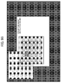
- FIG. 11B if the image projection area is modified by modifying resolution of the input signal, etc., and the display position of the menu is modified, the position of the selected option (option t) moves as indicated by the white arrow in FIG. 11B .
- US2011/017002A discloses displaying a menu by an OSD function in a projector and adjusting it according to variations in the main image.
- the invention is in the projector of Claim 1 and the method of Claim 6.
- a projector that can keep the displacement of the selected option to a minimum is provided, and it is possible to distinguish the selected option in the projection area after the modification without losing sight of the selected option.
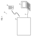
- FIG. 1 is a schematic diagram illustrating an image projection system 100.
- the image projection system 100 includes a projector 110 and a video source apparatus 120, and the projector 110 is connected to the video source apparatus 120 via a cable 130.
- the projector 110 in this embodiment generates the projection image based on the video signal and projects the projection image on the projection surface.
- the projector 110 includes a superimposed image projection unit (main controller 300, OSD generator 301, and projection unit 303) that superimposes a predetermined superimposed screen (OSD screen) on the generated projection image based on the video signal and projects the projection image and a signal control unit (signal controller 304) that detects variation of a projection area of the projection image based on the video signal.
- the superimposed image projection unit modifies the projection position of the superimposed image in accordance with the fluctuation of the projection area if the signal controller detects the fluctuation of the projection area of the projection image (e.g., change of screen resolution), generates a superimposed image that a display position of a part selected in the superimposed image before modifying and displayed differently from other parts is adjusted based on amount of variation of the projection position of the superimposed image along with the fluctuation, and the generated superimposed image is projected as the superimposed image after being modified.
- the signal controller detects the fluctuation of the projection area of the projection image (e.g., change of screen resolution)
- the signal controller detects the fluctuation of the projection area of the projection image (e.g., change of screen resolution)
- generates a superimposed image that a display position of a part selected in the superimposed image before modifying and displayed differently from other parts is adjusted based on amount of variation of the projection position of the superimposed image along with the fluctuation, and the generated superimposed image is projected as the superimposed image
- the projector 110 projects an image provided by the video source apparatus 120 on a projection surface such as a screen etc.
- the projector 110 projects an OSD screen (superimposed screen) such as a menu configurable manually along with the image provided by the video source apparatus 120. It should be noted that the OSD screen can be projected even if the video source apparatus 120 does not provide images.
- the projector 110 receives operation requests from a remote control 140 and performs various operations that implements functions that the projector 110 includes.
- the projector 110 includes video input ports such as a D-Sub connector as a Video Graphics Array (VGA) input port, a High-Definition Multimedia Interface (HDMI) port, a S-Video port, and a RCA port as interfaces for inputting video signals and receives the video signal from the video source apparatus 120 via the cable 130 connected to those ports.
- video input ports such as a D-Sub connector as a Video Graphics Array (VGA) input port, a High-Definition Multimedia Interface (HDMI) port, a S-Video port, and a RCA port as interfaces for inputting video signals and receives the video signal from the video source apparatus 120 via the cable 130 connected to those ports.
- VGA Video Graphics Array
- HDMI High-Definition Multimedia Interface
- S-Video port S-Video port
- RCA port RCA port
- the projector can receive the video signal from the video source apparatus 120 using wireless communication in conformity with wireless communication protocols such as Bluetooth and Wi-Fi etc.
- the video source apparatus 120 provides images that the projector 110 projects.
- the image providing apparatus 120 includes interfaces to output video signals and transfers the video signal that forms display images of the video source apparatus 120 to the projector 110 at a predetermined transfer rate (e.g., from 30 frame per second (fps) to 60 fps).
- the video source apparatus 120 also includes video output ports such as a VGA output port, the HDMI port, the S-Video port, and the RCA port as interfaces for outputting video signals and transfers the video signal to the projector 110 via the cable 130 connected to those ports.
- video output ports such as a VGA output port, the HDMI port, the S-Video port, and the RCA port as interfaces for outputting video signals and transfers the video signal to the projector 110 via the cable 130 connected to those ports.
- the video source apparatus 120 can transfer the video signal to the projector 110 using wireless communication.
- a notebook PC information processing apparatus
- the information processing apparatus that can provide the video signals such as a desktop PC, a tablet PC and a PDA can be adopted as the video source apparatus 120.
- the video source apparatus 120 while one video source apparatus 120 is connected to the projector 110, two or more video source apparatus 120 can be connected to the projector 110.
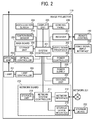
- FIG. 2 is a block diagram illustrating a configuration of the projector 110 in this embodiment.
- the projector 110 includes a main board 200, a network board (expansion board) 210, an optical unit 220, a lamp (light source) 221, a power supply 228, and a video signal input interface 230.
- the main board 200 is a printed-circuit board that controls the projector 110.
- the main board 200 includes a system controller 201, a video signal processor 202, a power supply controller 203, a storage device 204, an optical controller 205 and can be configured using integrated circuits that implement the functional units described above such as Application Specific Integrated Circuit (ASIC) etc.
- ASIC Application Specific Integrated Circuit
- the system controller 201 controls the projector 110.
- the system controller 201 is connected to the video signal processor 202, the power supply controller 203, the storage device 204, and the optical controller 205 via a bus and controls each of these functional units.
- the video signal processor 202 processes the video signal that the video source apparatus 120 provides.
- the video processor 202 receives the video signal via the video signal input interface 230 and performs various processes such as serial-parallel conversion and voltage level conversion etc.
- the power supply controller 203 controls the power supply 228 that supplies electric power to the projector 110.
- the power supply controller 203 turns on and off the power supply 228 under the control of the system controller 201.
- the storage device 204 is nonvolatile memory that stores various data that the system controller 201 processes.
- Various nonvolatile semiconductor memory devices including EPROM, EEPROM, and flash memory can be adopted as the storage device 204.
- the optical controller 205 controls the optical unit 220 that forms the video.
- the optical controller 205 supplies the image data that the system controller 201 generates to the optical unit 220 and forms the video of the image data.
- the optical unit 220 forms the video of the image data projects the image data on the projection surface by illuminating the optical unit 220 with the light generated by the lamp 221.
- the projector 110 is a liquid crystal projector, it is possible to adopt a liquid crystal as the optical unit 220.
- the projector 110 is a Digital Light Processing (DLP) projector, it is possible to adopt a DMD or a color wheel as the optical unit 220.
- DLP Digital Light Processing
- the lamp controller (light source controller) 222 controls the lamp 221 and adjust the amount of light of the lamp 221 under the control of the system controller 201. It is possible to use a high-pressure mercury vapor lamp etc. as the lamp 221.
- the network board 210 is a printed-circuit board that controls network communication and an external storage device.
- the network board 210 includes a network system controller 211, a network interface 212, a storage device interface 213, and a storage unit 214, and the network board 210 can be configured by integrated circuits such as ASIC that implements the function.
- the network system controller 211 controls communication via the network 231 and the storage device 232.
- the network system controller 211 is connected to the network interface 212, the storage device interface 213, and the storage unit 214 via a bus.
- the network interface 212 communicates data via the network 231.
- the network interface 212 provides the data received from the network 231 to the network system controller 211 and sends the data received from the network system controller 211 to the network 231.
- the network interface 212 includes a port that can be connected to a network cable such as a LAN cable etc. and performs wired communication via the network cable.
- the network interface 212 also includes a wireless communication function such as Bluetooth and Wi-Fi and performs data communication by wireless communication.
- the storage device interface 213 is an interface that connects to the portable storage device 232 such as a USB memory.
- the storage device interface 213 acquires image data such as an image and video and provides it to the network system controller 211.
- the storage unit 214 is a nonvolatile memory that stores various data processed by the network system controller 211.
- various nonvolatile semiconductor memory devices such as EPROM, EEPROM, and flash memory, etc., as the storage unit 214.
- the projector 110 includes a thermal sensor 223, an acceleration sensor, a display unit 225, an operational unit (main unit keys) 226, a receiver 227, and a cooling device 229, and these functional units are connected to the system controller 201 via a bus.
- the thermal sensor 223 detects temperature of the projector 110.
- the thermal sensor 223 reports the detected temperature to the system controller 201.
- the acceleration sensor 224 detects acceleration of the projector 110.
- the acceleration sensor 224 reports the detected temperature to the system controller 201
- the display unit 225 displays various information, and the display unit 225 is comprised of a LED indicator and a liquid crystal panel.
- the display unit 225 displays information to be displayed received from the system controller 201 on the LED indicator and the liquid crystal panel.
- the operational panel 226 accepts various operational requests manually and comprises key buttons (main unit keys) etc. laid out on the outside surface of the projector 110.
- the operational requests include a request to modify aspect ratio of the projected video, a request to turn off the projector 110, a request to change the lamp power to adjust the amount of light of the light source, a request to switch input that changes the image providing apparatus whose display image is to be projected if the multiple image providing apparatuses are connected, a request to change a video mode that changes quality of the projected video (e.g., bright, standard, and natural), a request to freeze that pauses the video to be projected, a request to change input type as type of port from which the image to be projected is acquired, a request to display the main menu or the sub-menu, a request to modify aspect ratio, and a request to close the sub-menu.
- the operational unit 226 reports the operational request to the system controller 201.
- the receiver 227 receives an operational signal from the remote control 140. After receiving the operational signal, the receiver 227 reports the operational signal to the system controller 201.
- the cooling device 229 cools down the projector 110 and is comprised of components such as a cooling fan, etc.
- the cooling device 229 is driven under the control of the system controller 201 and cools down the projector 110.
- FIG. 3 is a block diagram illustrating a configuration of the main board 200 included in the projector 110.
- the system controller 201 includes the main controller 300, the OSD generator 301, the main unit key/remote control controlling unit 302, the projection unit 303, and the signal controller 304.
- the main controller 300 controls the system controller 201.
- the main controller 300 controls the system controller 201 and functional units described above.
- the OSD generator 301 generates OSD screens such as menus, dialog boxes, message windows, icons, and help menus that the main board 200 generates.
- the OSD generator 301 reads menu settings information displayed on the main menu from the storage device 204 and generates the main menu that reflects the menu settings information.
- the OSD generator 301 transfers a video signal that forms the main menu to the projection unit 303.
- the main unit key/remote control controlling unit 302 accepts various operational requests from the operational unit 226 and the remote control 140 and reports the operational request that corresponds to each operational request.
- the projection unit 303 projects image data by controlling the optical controller 205.
- the projection unit 303 transfers a video signal that forms an image received from the image providing apparatus 120, a video signal that forms the menu etc. acquired from the OSD generator 301, and a video signal that forms a sub-menu acquired from the network board 210 to the optical controller 205 and projects those image data.
- the main controller 300, the OSD generator 301, and the projection unit 303 function as a superimposed image projection unit that superimposes the OSD screen (superimposed screen) on the generated projection screen based on the video signal and projects the superimposed image.
- the projector 110 includes the network board 210, a network board interface that performs data communication between the main board 200 and the network board 210.
- the network board interface transfers a request to display the sub-menu and close the sub-menu to the network board 210 and receives a response signal to these requests and a video signal that forms the sub-menu from the network board 210.
- the signal controller 304 functions as a signal controlling unit and determines the input video signal. That.is, if the video signal includes a modified image area (projection area), the signal controller 304 determines an image area that corresponds to the modified video signal.
- a process that modifies the image area means a process that changes coordinates of the projection image. Examples of that kind of process are changing resolution, changing an input type, adjusting keystone distortion, changing an aspect, and zooming in/out etc.
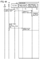
- FIGS. 4A , 4B and 4C are sequence charts illustrating a process executed by the projector 110.
- the OSD screen e.g., a menu
- the operational unit 226 manually in S101 (operation to display the menu).
- the receiver 227 transfers content of the operation to the main unit key/remote control controlling unit 302 in S 102 (instructing to display the menu), and the main unit key/remote control controlling unit 302 transfers the instruction to display the menu to the main controller 300 in S103 (instructing to display the menu).
- the main controller 300 instructs the OSD generator 301 to display the menu using the predetermined menu settings in S104 (instructing to display the menu).
- the OSD generator 301 acquires the projected image area from the main controller 300 in S107 (acquiring the projection area) and calculates coordinates of each component in the OSD screen (e.g., options and icons) from the coordinates of the image area in S108 (calculating the OSD coordinates).
- coordinates of each component in the OSD screen e.g., options and icons
- All components in the OSD screen hold coordinate positions (points of origin) if the image area starts at (x:0, y:0), e.g., the resolution is 1024x768, as their coordinate positions.
- the coordinate position for a component A is held as (x:50, y:50).
- sizes of each component are predetermined.
- the OSD generator 301 transfers the menu image to the projection unit 303 in S109 (displaying the OSD), and the projection unit 303 transfers a video signal for the menu image to the optical controller 205.
- the optical controller 205 projects the video signal in S110 (projecting the video). As described above, on the projection surface where the video from the video providing apparatus 120 is projected, it is possible to project the OSD screen corresponding to the image area of the video. How the coordinate positions are adjusted is described in detail below.
- the video signal processor 202 receives the video signal from the video providing apparatus 120 in S201 (modifying the video signal).
- the video signal processor 202 transfers the video signal to the main controller 300 in S202 (modifying the input signal). After receiving that, the main controller 300 instructs the signal controller 304 to examine the signal in S203 (examining the signal).
- the signal controller 304 examines the modified video signal and determines the projection area that corresponds to the resolution of the modified video signal in S204 (examining the signal and determining the projection area (signal controlling process)).
- the main controller 300 instructs the OSD generator 301 to adjust the display position of the menu in S205 (adjusting the menu position).
- the OSD generator 301 acquires the projection area from the main controller 300 in S206 (acquiring the projection area).
- the OSD generator 301 adjusts the coordinates of the menu in S207 (adjusting the OSD coordinates) and transfers the menu to the projection unit 303 in S208 (displaying the OSD).
- the steps in S207 and S208 are described in detail later.
- the main controller 300 instructs the projection unit 303 to display the video in S209 (projecting the video), and the projection unit 303 transfers the video signal of the menu image to the optical controller 205.
- the optical controller 205 projects the video signal in S210 (projecting the video).
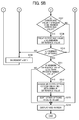
- FIGS. 5A and 5B are flowcharts illustrating steps from S205 to S208 (projecting the superimposed image) shown in FIG. 4 in detail. How the coordinates in the OSD screen are adjusted in modifying the image area is described below in detail with reference to the flowchart shown in FIG. 5 .
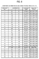
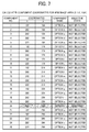
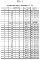
- FIGS. 6 , 7 , and 8 are tables illustrating component information such as coordinates of the components that comprise the OSD screen.
- FIG. 6 is a table illustrating component information in the case that the maximum projectable resolution is 1024x768, the origin of the image area (the upper left corner) is (x:0, y:0), and the endpoint of the image area (the lower right corner) is (x:1024, y:768).
- the OSD generator 301 stores the component information table.
- the component information table includes fields such as coordinates (origin), allocated name of component (option from a to y), and information that indicates whether or not the component is selected if the component is the option (hereinafter referred to as "selection information") for components that comprise the OSD screen (the components from No. 1 to No. 25) and holds each information.
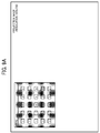
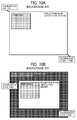
- FIG. 9A is a diagram illustrating the menu that an option t is selected and highlighted OSD-displayed on the upper left of the projection image whose resolution is 1024x768.
- the option t corresponds to the component No. 20, and its selective status indicates "selected".
- a new image area is acquired from the main controller 300 in S302 (S206).
- the origin of the new image area (its resolution is 800x600) is (x:112, y:84), and the endpoint is (x:912, y:684).
- FIG. 7 is a table illustrating component information in the case that the maximum projectable resolution is 800x600, the origin of the image area is (x:112, y:84), and the endpoint of the image area is (x:912, y:684).
- the OSD generator 301 calculates new coordinates of the components in the modified image area in S303.
- the coordinates of the components after modifying can be calculated by adding the coordinates of the origin to the coordinates of the components shown in FIG. 6 .
- the coordinates of the option is adjusted in S305 to S313. If there is no selected option (NO in S304), the OSD screen is displayed based on the component information table shown in FIG. 7 .
- the difference between the old coordinates (x:210, y:170) of the selected component (component No. 20, option t) shown in FIG. 6 and the new coordinates of the components shown in FIG. 7 are calculated below.
- 12.
- the minimum difference is 12 for the component No. 7.
- the calculated minimum difference is equal to or less than a predetermined threshold value (e.g., 100) in S311.
- a predetermined threshold value e.g. 100
- the optimal threshold value can be predetermined depending on the design of the OSD screen. In addition, it is preferable that the threshold value can be configured manually.
- the selected option (option t) is allotted to the component with the minimum difference (component No. 7) in S312.
- the other options are sorted and displayed so that the order of the other options from the upper left (options from a to y) shown in FIG. 9A is maintained in S313. That is, as shown in FIG. 8 , the option t is allotted to the component No. 7, the option u is allotted to the component No. 8, and the option m is allotted to the component No. 25 sequentially. Subsequently, the order returns to the upper left, the option n is allotted to the component No. 1, and the option s is allotted to the component No. 6. Accordingly, as shown in FIG. 9B , the coordinates for the options are adjusted. As described above, by maintaining the order of the options, it is possible that the user does not lose sight of the selected option.
- the coordinates of the selected option are adjusted to the position where the displacement is minimal.
- the adjustment that is easy to be recognized by the user.
- the option t is selected as shown in FIG. 9
- the position of the allotted selected option is determined based on the difference of the coordinates between before modifying and after modifying and the minimum difference as the calculation of the displacement of the selected option between before modifying and after modifying.
- the way of calculating the displacement is not limited to that.
- the button options from a to y are set in array on the menu as shown in FIG. 9 .
- the menu is displayed using bars, it is possible to adjust the coordinates so that the displacement of the selected bar is minimal.
- the options are sorted so that the order of the options is maintained in S313.
- the units from 300 to 304 included in the system controller 201 as described above can be configured by running software (control program), e.g., by the CPU on the projector.
- this invention may be implemented as convenient using a conventional general-purpose digital computer programmed according to the teachings of the present specification.
- Appropriate software coding can readily be prepared by skilled programmers based on the teachings of the present disclosure, as will be apparent to those skilled in the software arts.
- the present invention may also be implemented by the preparation of application-specific integrated circuits or by interconnecting an appropriate network of conventional component circuits, as will be readily apparent to those skilled in the relevant art.
- a processing circuit includes a programmed processor, as a processor includes circuitry.
- a processing circuit also includes devices such as an application specific integrated circuit (ASIC) and conventional circuit components arranged to perform the recited functions.
- ASIC application specific integrated circuit
Landscapes
- Engineering & Computer Science (AREA)
- Multimedia (AREA)
- Signal Processing (AREA)
- Physics & Mathematics (AREA)
- Theoretical Computer Science (AREA)
- General Physics & Mathematics (AREA)
- General Engineering & Computer Science (AREA)
- Computer Networks & Wireless Communication (AREA)
- Computer Hardware Design (AREA)
- Databases & Information Systems (AREA)
- Human Computer Interaction (AREA)
- Geometry (AREA)
- Controls And Circuits For Display Device (AREA)
- Projection Apparatus (AREA)
- Transforming Electric Information Into Light Information (AREA)
Claims (7)
- Projektor (110), umfassend:eine ein überlagertes Bild projizierende Projektoreinheit (300, 301, 303), welche zum Projizieren eines Projektionsbildes konfiguriert ist, basierend auf einem Videosignal, wobei das Projektionsbild ein darauf überlagertes vorbestimmtes überlagertes Bild aufweist, wobei das überlagerte Bild eine Anordnung von Darstellungen von benutzerauswählbaren Optionen (a - y in den Figuren 9A und 9B) umfasst, wobei jede Option anzeigt, ob sie ausgewählt worden ist; undeine Signalsteuerung (304), welche zum Erfassen von Änderungen im Projektionsbereich des projizierten Bildes auf der Basis des Videosignals konfiguriert ist;wobei die ein überlagertes Bild projizierende Projektoreinheit (300, 301, 303) zum Verändern der Projektionsposition des überlagerten Bildes gemäß der von der Signalsteuerung (304) erfassten Änderung im Projektionsbereich des projizierten Bildes und zum Umordnen der Positionen der Darstellungen der benutzerauswählbaren Optionen in der Anordnung konfiguriert ist, als Teil des Vorgangs des Veränderns der Projektionsposition des überlagerten Bildes, um so die Verlagerung einer ausgewählten der Optionen, aus ihrer Ausgangsposition bis zu ihrer geänderten Position im Projektionsbild, zu minimieren.
- Projektor nach Anspruch 1, wobei die Anordnung Reihen und Spalten der Darstellungen umfasst, und die ein überlagertes Bild projizierende Projektionseinheit (300, 301, 303) zum Umordnen der Positionen der Darstellungen, durch Sortieren in Einheiten von Reihen oder Spalten, konfiguriert ist.
- Projektor nach Anspruch 1, wobei die ein überlagertes Bild projizierende Projektionseinheit (300, 301, 303) zum Sortieren der Darstellungen der nicht ausgewählten Optionen konfiguriert ist, um so die Ordnung aller Optionen, von oben links nach unten rechts in der Anordnung, zu behalten.
- Projektor nach einem der Ansprüche 1 bis 3, wobei die ein überlagertes Bild projizierende Projektionseinheit (300, 301, 303) zum Ändern der Projektionsposition und zum Minimieren der Verlagerung der ausgewählten Option auf der Basis von Koordinatenpositionen im Projektionsbild konfiguriert ist.
- Projektor (110) nach einem der Ansprüche 1 bis 4, wobei die Signalsteuerung (304) zum Erfassen der Änderung des Projektionsbereiches des Projektionsbildes als Reaktion auf eine Änderung der Auflösung des Projektionsbildes, auf eine Änderung des Seitenverhältnis des Projektionsbildes oder auf ein Zoomen des Projektionsbildes konfiguriert ist.
- Verfahren zum Steuern eines Projektionsbildes, umfassend die Schritte:Projizieren eines Projektionsbildes, welches auf der Basis eines Videosignals erzeugt wird, wobei das Projektionsbild ein darauf überlagertes vorbestimmtes überlagertes Bild aufweist, wobei das überlagerte Bild eine Anordnung von Darstellungen von benutzerauswählbaren Optionen (a - y in den Figuren 9A und 9B) umfasst, wobei jede Option anzeigt, ob sie ausgewählt worden ist;Erfassen einer Änderung in einem Projektionsbereich des Projektionsbildes auf der Basis des Videosignals;Verändern einer Projektionsposition des überlagerten Bildes gemäß der Änderung im Projektionsbereich des Projektionsbildes;und Umordnen der Positionen der Darstellungen der benutzerauswählbaren Optionen in der Anordnung, als Teil des Vorgangs zum Verändern der Projektionsposition des überlagerten Bildes, um so die Verlagerung einer ausgewählten der Optionen, aus ihrer Ausgangsposition bis zu ihrer geänderten Position im Projektionsbild, zu minimieren.
- Computerlesbares Aufzeichnungsmedium, das ein Programm speichert, welches, wenn es von einem Projektor (110) ausgeführt wird, den Projektor (110) veranlasst, das Verfahren zum Steuern eines Projektionsbildes nach Anspruch 6 auszuführen.
Applications Claiming Priority (1)
| Application Number | Priority Date | Filing Date | Title |
|---|---|---|---|
| JP2013144437A JP6263881B2 (ja) | 2013-07-10 | 2013-07-10 | 画像投射装置、画像投射装置の制御方法、および画像投射装置の制御プログラム |
Publications (2)
| Publication Number | Publication Date |
|---|---|
| EP2824936A1 EP2824936A1 (de) | 2015-01-14 |
| EP2824936B1 true EP2824936B1 (de) | 2016-06-15 |
Family
ID=51033029
Family Applications (1)
| Application Number | Title | Priority Date | Filing Date |
|---|---|---|---|
| EP14175137.0A Not-in-force EP2824936B1 (de) | 2013-07-10 | 2014-07-01 | Projektor, Projektorsteuerungsverfahren und Aufzeichnungsmedium mit darauf gespeichertem Projektorsteuerungsprogramm |
Country Status (4)
| Country | Link |
|---|---|
| US (1) | US20150015583A1 (de) |
| EP (1) | EP2824936B1 (de) |
| JP (1) | JP6263881B2 (de) |
| CN (1) | CN104284117B (de) |
Families Citing this family (7)
| Publication number | Priority date | Publication date | Assignee | Title |
|---|---|---|---|---|
| EP3196871B1 (de) * | 2014-09-16 | 2019-11-06 | Ricoh Company, Ltd. | Anzeigevorrichtung, anzeigesystem und anzeigesteuerungsprogramm |
| JP2016161820A (ja) * | 2015-03-03 | 2016-09-05 | 株式会社リコー | 画像表示制御装置、画像表示制御プログラム、画像表示制御システム |
| CN107979748A (zh) * | 2016-10-21 | 2018-05-01 | 中强光电股份有限公司 | 投影机、投影系统以及影像投影方法 |
| JP6897191B2 (ja) * | 2017-03-17 | 2021-06-30 | セイコーエプソン株式会社 | プロジェクターおよびプロジェクターの制御方法 |
| US10349025B2 (en) * | 2017-07-27 | 2019-07-09 | Seiko Epson Corporation | Projector and method of controlling projector |
| WO2019043854A1 (ja) * | 2017-08-31 | 2019-03-07 | 三菱電機株式会社 | 光学機器制御装置、光学機器制御方法、及び光学機器制御プログラム |
| CN108737805B (zh) * | 2018-07-09 | 2020-03-27 | 北京一数科技有限公司 | 一种光机投影方法、装置及智能手表 |
Family Cites Families (11)
| Publication number | Priority date | Publication date | Assignee | Title |
|---|---|---|---|---|
| JP2002330364A (ja) * | 2001-04-27 | 2002-11-15 | Matsushita Electric Ind Co Ltd | オンスクリーン表示装置 |
| US7500186B2 (en) * | 2004-08-30 | 2009-03-03 | Microsoft Corporation | Systems and methods for efficiently generating table layouts using moveable items |
| WO2006098402A1 (ja) * | 2005-03-17 | 2006-09-21 | Brother Kogyo Kabushiki Kaisha | プロジェクタ |
| JP4079163B2 (ja) | 2005-05-30 | 2008-04-23 | ソニー株式会社 | 投影型画像表示装置 |
| JP4886300B2 (ja) * | 2006-01-20 | 2012-02-29 | 株式会社東芝 | 投射型表示装置、およびosd表示方法 |
| JP4884867B2 (ja) * | 2006-07-25 | 2012-02-29 | 任天堂株式会社 | 情報処理装置および情報処理プログラム |
| JP2009216815A (ja) * | 2008-03-07 | 2009-09-24 | Sanyo Electric Co Ltd | 投写型映像表示装置 |
| US8312387B2 (en) * | 2009-08-10 | 2012-11-13 | Microsoft Corporation | Target element zoom |
| JP5177120B2 (ja) * | 2009-11-10 | 2013-04-03 | 株式会社デンソー | 遠隔操作デバイス用表示制御装置 |
| JP2011142597A (ja) * | 2010-01-09 | 2011-07-21 | Seiko Epson Corp | プロジェクター及びその制御方法 |
| JP5832119B2 (ja) * | 2011-04-06 | 2015-12-16 | キヤノン株式会社 | 投影装置、その制御方法及びプログラム |
-
2013
- 2013-07-10 JP JP2013144437A patent/JP6263881B2/ja not_active Expired - Fee Related
-
2014
- 2014-06-27 US US14/317,187 patent/US20150015583A1/en not_active Abandoned
- 2014-07-01 EP EP14175137.0A patent/EP2824936B1/de not_active Not-in-force
- 2014-07-09 CN CN201410325242.8A patent/CN104284117B/zh not_active Expired - Fee Related
Also Published As
| Publication number | Publication date |
|---|---|
| CN104284117B (zh) | 2018-03-27 |
| JP6263881B2 (ja) | 2018-01-24 |
| EP2824936A1 (de) | 2015-01-14 |
| JP2015019195A (ja) | 2015-01-29 |
| CN104284117A (zh) | 2015-01-14 |
| US20150015583A1 (en) | 2015-01-15 |
Similar Documents
| Publication | Publication Date | Title |
|---|---|---|
| EP2824936B1 (de) | Projektor, Projektorsteuerungsverfahren und Aufzeichnungsmedium mit darauf gespeichertem Projektorsteuerungsprogramm | |
| JP5849560B2 (ja) | 表示装置、プロジェクター、及び、表示方法 | |
| EP1455267A2 (de) | Bildverarbeitungsvorrichtung und Programm | |
| US8462273B2 (en) | Image display device, projector, control method and computer program product | |
| JP6866591B2 (ja) | 表示システム、表示システムの制御方法、及びプログラム | |
| KR20100035924A (ko) | 디스플레이장치 및 외부입력장치를 가지는 디스플레이 시스템과 그 제어 방법 | |
| US9307210B2 (en) | Image output apparatus, method, and medium | |
| US9300905B2 (en) | Projector, projector control method, and recording medium storing projector control program | |
| US11528455B2 (en) | Control device, and control method | |
| JP2020035176A (ja) | 投影装置、投影装置の制御方法、プログラム、および記憶媒体 | |
| JP6349886B2 (ja) | 画像投射装置、画像投射装置の制御方法、および画像投射装置の制御プログラム | |
| JP7224799B2 (ja) | 画像投影装置、画像投影装置の制御方法、プログラム | |
| US20190065130A1 (en) | Display device and method for controlling display device | |
| US10397531B2 (en) | Projector, display device, and display method | |
| JP5944000B2 (ja) | 画像表示システム、情報端末、情報端末の制御方法及び制御プログラム | |
| US11276372B2 (en) | Method of operation of display device and display device | |
| JP4957009B2 (ja) | ネットワーク機能を有するプロジェクタを使用したプレゼンテーションシステムおよびプレゼンテーション方法 | |
| JP6894801B2 (ja) | 被制御装置およびその制御方法、プログラム並びに記憶媒体 | |
| JP2007212619A (ja) | 投射型画像表示装置 | |
| US20080174746A1 (en) | Method for projecting an image from one of a plurality of hosts and projection device thereof | |
| JP2016224291A (ja) | 表示装置、表示システム、及び、表示装置の制御方法 | |
| JP2013195659A (ja) | 表示装置、及び、表示制御方法 | |
| JP2006171853A (ja) | 表示装置、表示システム、表示制御方法、プログラムおよび記憶媒体 | |
| JP2010170423A (ja) | 情報処理装置およびプログラム | |
| JP2015155990A (ja) | 画像投影装置、画像投影システム、および画像投影装置の制御方法 |
Legal Events
| Date | Code | Title | Description |
|---|---|---|---|
| 17P | Request for examination filed |
Effective date: 20140701 |
|
| AK | Designated contracting states |
Kind code of ref document: A1 Designated state(s): AL AT BE BG CH CY CZ DE DK EE ES FI FR GB GR HR HU IE IS IT LI LT LU LV MC MK MT NL NO PL PT RO RS SE SI SK SM TR |
|
| AX | Request for extension of the european patent |
Extension state: BA ME |
|
| PUAI | Public reference made under article 153(3) epc to a published international application that has entered the european phase |
Free format text: ORIGINAL CODE: 0009012 |
|
| GRAP | Despatch of communication of intention to grant a patent |
Free format text: ORIGINAL CODE: EPIDOSNIGR1 |
|
| INTG | Intention to grant announced |
Effective date: 20160318 |
|
| GRAS | Grant fee paid |
Free format text: ORIGINAL CODE: EPIDOSNIGR3 |
|
| GRAA | (expected) grant |
Free format text: ORIGINAL CODE: 0009210 |
|
| AK | Designated contracting states |
Kind code of ref document: B1 Designated state(s): AL AT BE BG CH CY CZ DE DK EE ES FI FR GB GR HR HU IE IS IT LI LT LU LV MC MK MT NL NO PL PT RO RS SE SI SK SM TR |
|
| REG | Reference to a national code |
Ref country code: CH Ref legal event code: EP Ref country code: GB Ref legal event code: FG4D |
|
| REG | Reference to a national code |
Ref country code: IE Ref legal event code: FG4D |
|
| REG | Reference to a national code |
Ref country code: AT Ref legal event code: REF Ref document number: 807032 Country of ref document: AT Kind code of ref document: T Effective date: 20160715 |
|
| REG | Reference to a national code |
Ref country code: FR Ref legal event code: PLFP Year of fee payment: 3 |
|
| REG | Reference to a national code |
Ref country code: DE Ref legal event code: R096 Ref document number: 602014002304 Country of ref document: DE |
|
| REG | Reference to a national code |
Ref country code: LT Ref legal event code: MG4D |
|
| REG | Reference to a national code |
Ref country code: NL Ref legal event code: MP Effective date: 20160615 |
|
| PG25 | Lapsed in a contracting state [announced via postgrant information from national office to epo] |
Ref country code: NO Free format text: LAPSE BECAUSE OF FAILURE TO SUBMIT A TRANSLATION OF THE DESCRIPTION OR TO PAY THE FEE WITHIN THE PRESCRIBED TIME-LIMIT Effective date: 20160915 Ref country code: LT Free format text: LAPSE BECAUSE OF FAILURE TO SUBMIT A TRANSLATION OF THE DESCRIPTION OR TO PAY THE FEE WITHIN THE PRESCRIBED TIME-LIMIT Effective date: 20160615 Ref country code: FI Free format text: LAPSE BECAUSE OF FAILURE TO SUBMIT A TRANSLATION OF THE DESCRIPTION OR TO PAY THE FEE WITHIN THE PRESCRIBED TIME-LIMIT Effective date: 20160615 |
|
| REG | Reference to a national code |
Ref country code: AT Ref legal event code: MK05 Ref document number: 807032 Country of ref document: AT Kind code of ref document: T Effective date: 20160615 |
|
| PG25 | Lapsed in a contracting state [announced via postgrant information from national office to epo] |
Ref country code: RS Free format text: LAPSE BECAUSE OF FAILURE TO SUBMIT A TRANSLATION OF THE DESCRIPTION OR TO PAY THE FEE WITHIN THE PRESCRIBED TIME-LIMIT Effective date: 20160615 Ref country code: GR Free format text: LAPSE BECAUSE OF FAILURE TO SUBMIT A TRANSLATION OF THE DESCRIPTION OR TO PAY THE FEE WITHIN THE PRESCRIBED TIME-LIMIT Effective date: 20160916 Ref country code: NL Free format text: LAPSE BECAUSE OF FAILURE TO SUBMIT A TRANSLATION OF THE DESCRIPTION OR TO PAY THE FEE WITHIN THE PRESCRIBED TIME-LIMIT Effective date: 20160615 Ref country code: HR Free format text: LAPSE BECAUSE OF FAILURE TO SUBMIT A TRANSLATION OF THE DESCRIPTION OR TO PAY THE FEE WITHIN THE PRESCRIBED TIME-LIMIT Effective date: 20160615 Ref country code: LV Free format text: LAPSE BECAUSE OF FAILURE TO SUBMIT A TRANSLATION OF THE DESCRIPTION OR TO PAY THE FEE WITHIN THE PRESCRIBED TIME-LIMIT Effective date: 20160615 Ref country code: SE Free format text: LAPSE BECAUSE OF FAILURE TO SUBMIT A TRANSLATION OF THE DESCRIPTION OR TO PAY THE FEE WITHIN THE PRESCRIBED TIME-LIMIT Effective date: 20160615 |
|
| PG25 | Lapsed in a contracting state [announced via postgrant information from national office to epo] |
Ref country code: BE Free format text: LAPSE BECAUSE OF NON-PAYMENT OF DUE FEES Effective date: 20160731 |
|
| PG25 | Lapsed in a contracting state [announced via postgrant information from national office to epo] |
Ref country code: EE Free format text: LAPSE BECAUSE OF FAILURE TO SUBMIT A TRANSLATION OF THE DESCRIPTION OR TO PAY THE FEE WITHIN THE PRESCRIBED TIME-LIMIT Effective date: 20160615 Ref country code: SK Free format text: LAPSE BECAUSE OF FAILURE TO SUBMIT A TRANSLATION OF THE DESCRIPTION OR TO PAY THE FEE WITHIN THE PRESCRIBED TIME-LIMIT Effective date: 20160615 Ref country code: IT Free format text: LAPSE BECAUSE OF FAILURE TO SUBMIT A TRANSLATION OF THE DESCRIPTION OR TO PAY THE FEE WITHIN THE PRESCRIBED TIME-LIMIT Effective date: 20160615 Ref country code: IS Free format text: LAPSE BECAUSE OF FAILURE TO SUBMIT A TRANSLATION OF THE DESCRIPTION OR TO PAY THE FEE WITHIN THE PRESCRIBED TIME-LIMIT Effective date: 20161015 Ref country code: CZ Free format text: LAPSE BECAUSE OF FAILURE TO SUBMIT A TRANSLATION OF THE DESCRIPTION OR TO PAY THE FEE WITHIN THE PRESCRIBED TIME-LIMIT Effective date: 20160615 Ref country code: RO Free format text: LAPSE BECAUSE OF FAILURE TO SUBMIT A TRANSLATION OF THE DESCRIPTION OR TO PAY THE FEE WITHIN THE PRESCRIBED TIME-LIMIT Effective date: 20160615 |
|
| PG25 | Lapsed in a contracting state [announced via postgrant information from national office to epo] |
Ref country code: AT Free format text: LAPSE BECAUSE OF FAILURE TO SUBMIT A TRANSLATION OF THE DESCRIPTION OR TO PAY THE FEE WITHIN THE PRESCRIBED TIME-LIMIT Effective date: 20160615 Ref country code: BE Free format text: LAPSE BECAUSE OF FAILURE TO SUBMIT A TRANSLATION OF THE DESCRIPTION OR TO PAY THE FEE WITHIN THE PRESCRIBED TIME-LIMIT Effective date: 20160615 Ref country code: ES Free format text: LAPSE BECAUSE OF FAILURE TO SUBMIT A TRANSLATION OF THE DESCRIPTION OR TO PAY THE FEE WITHIN THE PRESCRIBED TIME-LIMIT Effective date: 20160615 Ref country code: PL Free format text: LAPSE BECAUSE OF FAILURE TO SUBMIT A TRANSLATION OF THE DESCRIPTION OR TO PAY THE FEE WITHIN THE PRESCRIBED TIME-LIMIT Effective date: 20160615 Ref country code: SM Free format text: LAPSE BECAUSE OF FAILURE TO SUBMIT A TRANSLATION OF THE DESCRIPTION OR TO PAY THE FEE WITHIN THE PRESCRIBED TIME-LIMIT Effective date: 20160615 Ref country code: PT Free format text: LAPSE BECAUSE OF FAILURE TO SUBMIT A TRANSLATION OF THE DESCRIPTION OR TO PAY THE FEE WITHIN THE PRESCRIBED TIME-LIMIT Effective date: 20161017 |
|
| REG | Reference to a national code |
Ref country code: DE Ref legal event code: R097 Ref document number: 602014002304 Country of ref document: DE |
|
| PG25 | Lapsed in a contracting state [announced via postgrant information from national office to epo] |
Ref country code: MC Free format text: LAPSE BECAUSE OF FAILURE TO SUBMIT A TRANSLATION OF THE DESCRIPTION OR TO PAY THE FEE WITHIN THE PRESCRIBED TIME-LIMIT Effective date: 20160615 |
|
| PLBE | No opposition filed within time limit |
Free format text: ORIGINAL CODE: 0009261 |
|
| STAA | Information on the status of an ep patent application or granted ep patent |
Free format text: STATUS: NO OPPOSITION FILED WITHIN TIME LIMIT |
|
| REG | Reference to a national code |
Ref country code: IE Ref legal event code: MM4A |
|
| 26N | No opposition filed |
Effective date: 20170316 |
|
| PG25 | Lapsed in a contracting state [announced via postgrant information from national office to epo] |
Ref country code: DK Free format text: LAPSE BECAUSE OF FAILURE TO SUBMIT A TRANSLATION OF THE DESCRIPTION OR TO PAY THE FEE WITHIN THE PRESCRIBED TIME-LIMIT Effective date: 20160615 |
|
| REG | Reference to a national code |
Ref country code: FR Ref legal event code: PLFP Year of fee payment: 4 |
|
| PG25 | Lapsed in a contracting state [announced via postgrant information from national office to epo] |
Ref country code: IE Free format text: LAPSE BECAUSE OF NON-PAYMENT OF DUE FEES Effective date: 20160701 |
|
| PG25 | Lapsed in a contracting state [announced via postgrant information from national office to epo] |
Ref country code: LU Free format text: LAPSE BECAUSE OF NON-PAYMENT OF DUE FEES Effective date: 20160701 Ref country code: SI Free format text: LAPSE BECAUSE OF FAILURE TO SUBMIT A TRANSLATION OF THE DESCRIPTION OR TO PAY THE FEE WITHIN THE PRESCRIBED TIME-LIMIT Effective date: 20160615 |
|
| REG | Reference to a national code |
Ref country code: CH Ref legal event code: PL |
|
| PG25 | Lapsed in a contracting state [announced via postgrant information from national office to epo] |
Ref country code: CH Free format text: LAPSE BECAUSE OF NON-PAYMENT OF DUE FEES Effective date: 20170731 Ref country code: LI Free format text: LAPSE BECAUSE OF NON-PAYMENT OF DUE FEES Effective date: 20170731 |
|
| PG25 | Lapsed in a contracting state [announced via postgrant information from national office to epo] |
Ref country code: HU Free format text: LAPSE BECAUSE OF FAILURE TO SUBMIT A TRANSLATION OF THE DESCRIPTION OR TO PAY THE FEE WITHIN THE PRESCRIBED TIME-LIMIT; INVALID AB INITIO Effective date: 20140701 |
|
| PG25 | Lapsed in a contracting state [announced via postgrant information from national office to epo] |
Ref country code: CY Free format text: LAPSE BECAUSE OF FAILURE TO SUBMIT A TRANSLATION OF THE DESCRIPTION OR TO PAY THE FEE WITHIN THE PRESCRIBED TIME-LIMIT Effective date: 20160615 Ref country code: MT Free format text: LAPSE BECAUSE OF NON-PAYMENT OF DUE FEES Effective date: 20160731 Ref country code: MK Free format text: LAPSE BECAUSE OF FAILURE TO SUBMIT A TRANSLATION OF THE DESCRIPTION OR TO PAY THE FEE WITHIN THE PRESCRIBED TIME-LIMIT Effective date: 20160615 |
|
| REG | Reference to a national code |
Ref country code: FR Ref legal event code: PLFP Year of fee payment: 5 |
|
| PG25 | Lapsed in a contracting state [announced via postgrant information from national office to epo] |
Ref country code: BG Free format text: LAPSE BECAUSE OF FAILURE TO SUBMIT A TRANSLATION OF THE DESCRIPTION OR TO PAY THE FEE WITHIN THE PRESCRIBED TIME-LIMIT Effective date: 20160615 |
|
| PG25 | Lapsed in a contracting state [announced via postgrant information from national office to epo] |
Ref country code: TR Free format text: LAPSE BECAUSE OF FAILURE TO SUBMIT A TRANSLATION OF THE DESCRIPTION OR TO PAY THE FEE WITHIN THE PRESCRIBED TIME-LIMIT Effective date: 20160615 Ref country code: AL Free format text: LAPSE BECAUSE OF FAILURE TO SUBMIT A TRANSLATION OF THE DESCRIPTION OR TO PAY THE FEE WITHIN THE PRESCRIBED TIME-LIMIT Effective date: 20160615 |
|
| PGFP | Annual fee paid to national office [announced via postgrant information from national office to epo] |
Ref country code: GB Payment date: 20200727 Year of fee payment: 7 Ref country code: FR Payment date: 20200723 Year of fee payment: 7 Ref country code: DE Payment date: 20200721 Year of fee payment: 7 |
|
| REG | Reference to a national code |
Ref country code: DE Ref legal event code: R119 Ref document number: 602014002304 Country of ref document: DE |
|
| GBPC | Gb: european patent ceased through non-payment of renewal fee |
Effective date: 20210701 |
|
| PG25 | Lapsed in a contracting state [announced via postgrant information from national office to epo] |
Ref country code: GB Free format text: LAPSE BECAUSE OF NON-PAYMENT OF DUE FEES Effective date: 20210701 Ref country code: DE Free format text: LAPSE BECAUSE OF NON-PAYMENT OF DUE FEES Effective date: 20220201 |
|
| PG25 | Lapsed in a contracting state [announced via postgrant information from national office to epo] |
Ref country code: FR Free format text: LAPSE BECAUSE OF NON-PAYMENT OF DUE FEES Effective date: 20210731 |