EP2825123B1 - Oszillierendes zahnärztliches winkelstück - Google Patents
Oszillierendes zahnärztliches winkelstück Download PDFInfo
- Publication number
- EP2825123B1 EP2825123B1 EP13723209.6A EP13723209A EP2825123B1 EP 2825123 B1 EP2825123 B1 EP 2825123B1 EP 13723209 A EP13723209 A EP 13723209A EP 2825123 B1 EP2825123 B1 EP 2825123B1
- Authority
- EP
- European Patent Office
- Prior art keywords
- angle handpiece
- dental
- oscillating
- tool
- driven holder
- Prior art date
- Legal status (The legal status is an assumption and is not a legal conclusion. Google has not performed a legal analysis and makes no representation as to the accuracy of the status listed.)
- Not-in-force
Links
- 230000008878 coupling Effects 0.000 claims description 7
- 238000010168 coupling process Methods 0.000 claims description 7
- 238000005859 coupling reaction Methods 0.000 claims description 7
- 229920002994 synthetic fiber Polymers 0.000 claims description 5
- 230000010355 oscillation Effects 0.000 claims description 4
- 230000003247 decreasing effect Effects 0.000 claims 1
- 238000011282 treatment Methods 0.000 description 4
- 238000005498 polishing Methods 0.000 description 2
- 239000004677 Nylon Substances 0.000 description 1
- 239000004696 Poly ether ether ketone Substances 0.000 description 1
- 239000004952 Polyamide Substances 0.000 description 1
- JUPQTSLXMOCDHR-UHFFFAOYSA-N benzene-1,4-diol;bis(4-fluorophenyl)methanone Chemical compound OC1=CC=C(O)C=C1.C1=CC(F)=CC=C1C(=O)C1=CC=C(F)C=C1 JUPQTSLXMOCDHR-UHFFFAOYSA-N 0.000 description 1
- 230000001419 dependent effect Effects 0.000 description 1
- 238000004519 manufacturing process Methods 0.000 description 1
- 239000000463 material Substances 0.000 description 1
- 239000007769 metal material Substances 0.000 description 1
- 238000012986 modification Methods 0.000 description 1
- 230000004048 modification Effects 0.000 description 1
- 238000000465 moulding Methods 0.000 description 1
- 229920001778 nylon Polymers 0.000 description 1
- 239000004033 plastic Substances 0.000 description 1
- 229920002647 polyamide Polymers 0.000 description 1
- 239000004417 polycarbonate Substances 0.000 description 1
- 229920000515 polycarbonate Polymers 0.000 description 1
- 229920002530 polyetherether ketone Polymers 0.000 description 1
- 238000011321 prophylaxis Methods 0.000 description 1
- 239000012763 reinforcing filler Substances 0.000 description 1
Images




Classifications
-
- A—HUMAN NECESSITIES
- A61—MEDICAL OR VETERINARY SCIENCE; HYGIENE
- A61C—DENTISTRY; APPARATUS OR METHODS FOR ORAL OR DENTAL HYGIENE
- A61C1/00—Dental machines for boring or cutting ; General features of dental machines or apparatus, e.g. hand-piece design
- A61C1/08—Machine parts specially adapted for dentistry
- A61C1/14—Tool-holders, i.e. operating tool holders, e.g. burr holders
- A61C1/148—Non-rotating tool holders, e.g. vibrating, oscillating, nutating
-
- A—HUMAN NECESSITIES
- A61—MEDICAL OR VETERINARY SCIENCE; HYGIENE
- A61C—DENTISTRY; APPARATUS OR METHODS FOR ORAL OR DENTAL HYGIENE
- A61C1/00—Dental machines for boring or cutting ; General features of dental machines or apparatus, e.g. hand-piece design
- A61C1/08—Machine parts specially adapted for dentistry
- A61C1/12—Angle hand-pieces
-
- A—HUMAN NECESSITIES
- A61—MEDICAL OR VETERINARY SCIENCE; HYGIENE
- A61C—DENTISTRY; APPARATUS OR METHODS FOR ORAL OR DENTAL HYGIENE
- A61C15/00—Devices for cleaning between the teeth
- A61C15/04—Dental floss; Floss holders
- A61C15/046—Flossing tools
- A61C15/048—Flossing tools with heads removable from handle, e.g. interchangeable heads
-
- A—HUMAN NECESSITIES
- A61—MEDICAL OR VETERINARY SCIENCE; HYGIENE
- A61C—DENTISTRY; APPARATUS OR METHODS FOR ORAL OR DENTAL HYGIENE
- A61C17/00—Devices for cleaning, polishing, rinsing or drying teeth, teeth cavities or prostheses; Saliva removers; Dental appliances for receiving spittle
- A61C17/005—Devices for dental prophylaxis
-
- A—HUMAN NECESSITIES
- A61—MEDICAL OR VETERINARY SCIENCE; HYGIENE
- A61C—DENTISTRY; APPARATUS OR METHODS FOR ORAL OR DENTAL HYGIENE
- A61C15/00—Devices for cleaning between the teeth
- A61C15/04—Dental floss; Floss holders
- A61C15/046—Flossing tools
- A61C15/047—Flossing tools power-driven
Definitions
- the present invention refers to a dental angle handpiece equipped with oscillating movement for dental tools. More specifically, the invention refers to an oscillating dental angle handpiece suitable for being used as a disposable angle handpiece.
- Oscillating dental handpieces transmit an alternating back-and-forth linear oscillating movement to the tool.
- Non-limiting examples of such tools are files, strips and polishing tools.
- Such oscillating movement tools are particularly useful in interproximal prophylaxis, restorative or orthodontics treatments.
- Documents US 5 340 310 A and US 3 552 022 A1 disclose a dental angle handpiece equipped with oscillating movement for dental tools according to the preamble of claim 1.
- the purpose of the present invention is to make an oscillating dental angle handpiece that can be used as a disposable angle handpiece.
- Another purpose of the present invention is to make an oscillating dental angle handpiece to which it is possible to fix different types of tools.
- a further purpose of the present invention is to make an oscillating dental angle handpiece that allows the tools to be oriented.
- Another purpose of the present invention is to make an oscillating dental angle handpiece that is particularly simple and functional, with low costs.
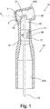
- an oscillating dental angle handpiece equipped with oscillating movement for dental tools is shown wholly indicated with 10 and comprising a hollow housing body 12, that defines a first longitudinal cavity 12A suitable for containing inside it, in a coaxial manner, a driving shaft 13 and a second transversal cavity 12B, 112B, arranged at an end of the first cavity 12A and having its axis incident with the axis of the first cavity 12A, suitable for containing a driven holder 20, schematically shown in figure 1 , the different variant embodiments of which 20', 20", 20'" not forming part of the invention and 120 of the invention are shown for example in figures 5 - 9 .
- the driving shaft 13 is suitable for being set in rotation by an external micromotor, not shown.
- the transfer of the rotary motion from the micromotor to the driving shaft 13 takes place through an adapter handle 11, shown as an example only in figure 5 , able to be connected to any of the angle handpieces 10 according to the invention.
- the angle handpiece 10 could also be directly connected to the micromotor.
- the driving shaft 13 comprises a plurality of annular projections 14, having a diameter slightly smaller than the diameter of the portion of the hollow housing body coupled with them, which keep the driving shaft 13 coaxial with the hollow body 12 during rotation.
- the annular projections 14 also constitute coupling elements for a locking cap 16, which is positioned in a hole 17 of the hollow body 12 after the axial mounting of the driving shaft 13 in the hollow body 12 to keep the driving shaft 13 axially in position.
- annular seat 15 for the engagement of the end of the locking cap 16 ( figures 2 and 3 ) or one of the annular projections 14 themselves is received between two projecting teeth of the locking cap 16 ( figure 6 ).
- the rotary movement of the driving shaft 13 is transformed into alternating back-and-forth linear oscillating movement of the tool through a cam connection between a cam 18, made in the form of a cylinder arranged at the end of the driving shaft 13 in non-coaxial position, in other words offset with respect to the rotation axis of the driving shaft 13, and the driven holder 20, equipped with a suitable seat 21, 121, having width x slightly greater than the diameter of the cam 18, measured in the direction parallel to the translation axis F of the linear oscillating movement.
- the cam 18 pulls the driven holder 20 with it, forcing it to carry out an oscillating back-and-forth movement along an axis F.
- the driven holder 20 is driven in its oscillating movement by the walls of the second cavity 12B, 112B of the hollow housing body 12, which in the example shown as an example and not for limiting purposes is arranged with a non-perpendicular angle with respect to the axis of the driving shaft 13.
- the oscillation axis is also arranged with a non-perpendicular angle with respect to the rotation axis of the driving shaft 13.
- the handpiece 10 generates an alternating linear oscillating movement of the driven holder 20 that can have different lengths, for example comprised between 0.1mm and 5mm.
- the driven holder 20, according to the invention, is not subject to any rotary movement about the translation axis.
- the driven holder 20 is schematically shown in figure 1 , without the tool itself.
- the tool can be removably connectable to the driven holder ( figures 2 , 3 and 5-9 ) or according to an embodiment not forming part of the invention it can be made as an enbloc with it ( figure 4 ).
- the angle handpiece 10 is made entirely from synthetic material, for example polycarbonate, polyamide (such as Nylon), PEEK, possibly containing reinforcing fillers.
- the angle handpiece made from synthetic material can optionally also be sterilizable, which is not strictly necessary for a disposable angle handpiece.
- Figure 2 shows a section of an embodiment of the oscillating angle handpiece 10, not forming part of the invention, coinciding with what is shown and described for the angle handpiece 10 of figure 1 , equipped with a first embodiment of the driven holder 20' suitable for receiving the tool in a removable manner.
- the driven holder 20' is provided with a hole 22, parallel to the direction of oscillation, suitable for receiving a shank 30 of a dental tool in removable engagement.
- the shank 30 can be made as an enbloc with the tool, according to an example not shown, or, as shown in figure 2 , it can be suitable for receiving, in removable engagement in a suitable seat 31, a dental tool, non-limiting examples of which are shown in international application WO 2010095017 A1 , which should be integrally referred to here.
- the engagement seat 31 for the dental tool is further provided with an elastic retaining tooth 32 for snap-locking with the fastening portion of the tool.
- the removable shank 30 can be rotated inside its seat, consisting of the hole 22, by 360° in order to orient the dental tool with respect to the most suitable position for the specific dental treatment, according to any desired angle, in other words according to continuous positions.
- a retaining ring 23 (O-ring) ensures sufficient friction with respect to the rotation, so that the dental tool, in use, is not subject to rotation with respect to the handpiece 10.
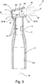
- FIG 3 shows a section of an embodiment of the oscillating angle handpiece 10, not forming part of the invention, coinciding with what is shown and described for the angle handpiece 10 of figures 1 and 2 , equipped with a second embodiment of the driven holder 20" also suitable for removably receiving the tool 33.
- the driven holder 20" is made in two portions, a front portion 20"A suitable for carrying the tool and a rear portion 20"B coupled with the driving shaft 13. The two portions are connected together through an articulation 24 so as to allow a mutual rotation substantially equal to 360° in order to orient the dental tool with respect to the most suitable position for the specific dental treatment, according to any desired angle, in other words according to continuous positions.
- the retaining ring 23, of the O-ring type, positioned near the articulation, ensures sufficient friction with respect to the rotation, so that the dental tool, in use, is not subject to rotation with respect to the handpiece 10.
- the front portion 20"A in the example shown in figure 3 , comprises a piece of shank 30', made as an enbloc with such a front portion 20"A and equipped with the seat 31 for the removal engagement with a dental tool, of the type described for the embodiment of figure 2 , in particular equipped with the elastic retaining tooth 32 for the snap-locking with the fastening portion of the tool.
- the driven holder 20'" comprises a front portion 20'"A directly carrying a dental tool 33 made as an enbloc with the angle handpiece 10, in other words not removable with respect to the driven holder 20'".
- the tool made as an enbloc with the driven holder could have a fixed orientation, in other words not be rotatable about the axis parallel to the direction of oscillation, or such a rotation could be carried out with other equivalent means to the articulation 24 to carry out a continuous or discrete adjustment of the position.
- the driven holder 20', 20", 20'" and the second cavity 12B of the hollow housing body 12 that receives it have a matching cylindrical shape.
- the hollow housing body 112B and the driven holder 120 have, along their shell, a matching conical shape, preferable in order to simplify the production by moulding of the pieces made from synthetic material, with the exception of a flat coupling portion parallel to the translation axis F.
- the driven holder 120 has, on the outer shell, a flat portion 25 oriented according to the translation axis F of the linear oscillating movement and arranged on the diametrically opposite side with respect to the seat for the cam 121.
- the second cavity 112B of the hollow housing body 12 is consequently equipped with a matching plane 19, projecting inside the cavity and also oriented according to the translation axis F of the linear oscillating movement.
- the cam 18, according to this embodiment, is received in a seat 121, the height y of which measured in the direction perpendicular to the translation axis F is progressively shorter in the direction of the end with a larger diameter of the conical driven holder 120, in other words at the end suitable for receiving the tool.
- the seat 121 has a bottom wall that when the angle handpiece is mounted is parallel to the front wall of the cam 18 facing it.
- This particular coupling between the cam 18 and the seat 121 is selected to act jointly with the coupling between the driven holder 120 and the cavity 112B on a plane parallel to the direction of translation F to ensure that the movement of the tool is exclusively alternating linear oscillating. Indeed, during the rotation of the driving shaft 13, the cam 18 keeps the driven holder 120 constantly in contact with the cavity 112B along the flat coupling.
- the two characteristics could also have application separately.
- the hole 22 of the driven holder 120, which receives the shank 30, is made axially centred.
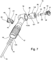
- the shank 30 preferably provides a seat 34 for holding the O-Ring 23 and a slit 35 at the opposite end with respect to the engagement seat 31 of the tool for the removable engagement with the projecting pin 41 of the safety cap 40.
- the safety cap 40 which holds the shank 30 in the holder when the angle handpiece 10 is operating, is shown in figures 5-9 in the removable embodiment.
- the safety cap 40 comprises two opposite pins 42 suitable for engaging in suitable seats 26 of the driven holder 120 constituting a bayonet locking mechanism.
- the clockwise or anticlockwise rotation given to the safety cap 40 acting on an external grip element 43 allows the locking or the release of the bayonet mechanism.
- the oscillating dental angle handpiece 10 according to the invention can be combined with any dental tool to be moved with oscillating motion, like for example files, strips, and polishing tools.
- any dental tool to be moved with oscillating motion like for example files, strips, and polishing tools.
- the tools described and shown should be taken as examples and not for limiting purposes.
- the oscillating dental angle handpiece 10 is assembled by firstly inserting the driven holder 20, 120 inside the second cavity 12B, 112B of the hollow housing body 12 and then axially introducing the driving shaft 13 inside the first cavity 12A of the hollow housing body 12 until the cam 18 is introduced into the seat 21.
- the locking cap 16 inserted from the outside into the hole 17 of the hollow housing body 12 and engaged in the annular seat 15 determines the stable axial positioning of the driving shaft 13 in the hollow housing body 12.
- the annular configuration of the seat 15 allows the relative rotation between the driving shaft 13 and the hollow housing body 12.
- the shank 30 made as a separate piece, it is thus inserted in the driven holder and removably or fixedly coupled with it.
- the oscillating dental angle handpiece according to the present invention has the advantage of being made entirely from plastic. Therefore, advantageously, the oscillating dental angle handpiece according to the invention is suitable for being used as a disposable angle handpiece.
- a further advantage consists of the possibility of easily replacing the driven holder to allow the operator to select the type of fastening of the dental tool that is preferred on each occasion, keeping the other components of the oscillating angle handpiece unchanged. As a result it has great versatility with respect to the possible combinations without penalizing the number of single components to be bought by the operator and to be kept in storage.
- the oscillating dental angle handpiece according to the invention is also advantageously equipped with exclusively alternating linear oscillating movement that allows the maximum precision in carrying out dental treatment.
- oscillating angle handpiece thus conceived can undergo numerous modifications and variants, all of which are covered by the invention; moreover, all of the details can be replaced by technically equivalent elements.
- the materials used, as well as the sizes, can be whatever according to the technical requirements.
Landscapes
- Health & Medical Sciences (AREA)
- Oral & Maxillofacial Surgery (AREA)
- Dentistry (AREA)
- Epidemiology (AREA)
- Life Sciences & Earth Sciences (AREA)
- Animal Behavior & Ethology (AREA)
- General Health & Medical Sciences (AREA)
- Public Health (AREA)
- Veterinary Medicine (AREA)
- Dental Tools And Instruments Or Auxiliary Dental Instruments (AREA)
Claims (4)
- Oszillierendes zahnärztliches Winkelstück für Dentalinstrumente, das vollständig aus synthetischem Material hergestellt ist und ein hohles Aufnahmegehäuse (12) umfasst, das einen ersten längslaufenden Hohlraum (12A) definiert, der geeignet ist, im Inneren auf koaxiale Weise eine Antriebswelle (13) aufzunehmen, und einen zweiten querlaufenden Hohlraum (112B), der an einem Endabschnitt des ersten Hohlraums (12A) angeordnet ist und eine Achse aufweist, die mit der Achse des ersten Hohlraums (12A) zusammenfällt, sowie einen antreibbaren Halter (120), der austauschbar ist, wobei eine Drehbewegung der Antriebswelle (13) in eine lineare, alternierende oszillierende Bewegung umgewandelt wird mittels einer Nockenverbindung zwischen einer Nocke (18), in Form eines am Ende der Antriebswelle (13) in einer nicht-koaxialen Position hierzu angeordneten Zylinders, und einem Sitz (121) des antreibbaren Halters (120) des Instruments, dessen Breite (x), gemessen in Parallelrichtung zur Translationsachse (F) der linearen oszillierenden Bewegung, etwas größer als der Durchmesser der Nocke (18) ist, und wobei der antreibbare Halter (120) mit einer axial zentrierten Bohrung (22) - parallel zur Oszillationsrichtung - versehen ist, die einen Schaft (30) eines Dentalinstruments lösbar in Eingriff nimmt, dadurch gekennzeichnet, dass das oszillierende zahnärztliche Winkelstück weiter eine Sicherheitskappe (40) umfasst, die in den Schaft (30) auf lösbare Weise einkuppelbar ist, wobei die Sicherheitskappe (40) einen auskragenden Stift (41) umfasst, in dem ein Haltering (23), beispielsweise ein O-Ring, zwischen die Bohrung (22) und den Schaft (30) eingefügt ist, wodurch eine Ausrichtung des Schafts in stufenlose Positionen ermöglicht wird, wobei der Schaft (30) mit einem Schlitz (35) am entgegengesetzten Ende in Bezug auf das Instrument zur lösbaren Ineingriffnahme des auskragenden Stifts (41) der Sicherheitskappe (40) versehen ist, wobei das hohle Aufnahmegehäuse (12) und der antreibbare Halter (120) eine übereinstimmende konische Form längs ihres Mantels aufweisen, mit Ausnahme eines flachen Kupplungsabschnitts (19, 25), der parallel zur Translationsachse (F) auf der diametral gegenüberliegenden Seite des antreibbaren Halters (120) in Bezug auf den Sitz (121) für die Nocke (18) angeordnet ist, und wobei der Sitz (121) eine in rechtwinkliger Richtung zur Translationsachse (F) gemessene Höhe (y) aufweist, die zum Instrument hin abnimmt.
- Winkelstück nach Anspruch 1, dadurch gekennzeichnet, dass die Kappe (40) durch einen Bajonett-Verriegelungsmechanismus lösbar mit dem antreibbaren Halter (120) verbunden werden kann.
- Winkelstück nach einem der vorstehenden Ansprüche, dadurch gekennzeichnet, dass die Antriebswelle (13) eine Mehrzahl von ringförmigen Auskragungen (14) umfasst, die einen etwas kleineren Durchmesser als der Durchmesser eines Abschnitts des hohlen Aufnahmegehäuses (12) aufweisen, der mit ihnen gekuppelt ist, wobei die ringförmigen Auskragungen (14) auch Kupplungselemente für eine Verriegelungskappe (16) bilden, die in einer Bohrung (17) des hohlen Gehäuses (12) angeordnet ist.
- Winkelstück nach einem der vorstehenden Ansprüche, dadurch gekennzeichnet, dass das synthetische Material sterilisiert werden kann.
Applications Claiming Priority (2)
| Application Number | Priority Date | Filing Date | Title |
|---|---|---|---|
| US201261609799P | 2012-03-12 | 2012-03-12 | |
| PCT/IB2013/051937 WO2013136262A1 (en) | 2012-03-12 | 2013-03-12 | Oscillating dental angle handpiece |
Publications (2)
| Publication Number | Publication Date |
|---|---|
| EP2825123A1 EP2825123A1 (de) | 2015-01-21 |
| EP2825123B1 true EP2825123B1 (de) | 2018-08-08 |
Family
ID=48446413
Family Applications (1)
| Application Number | Title | Priority Date | Filing Date |
|---|---|---|---|
| EP13723209.6A Not-in-force EP2825123B1 (de) | 2012-03-12 | 2013-03-12 | Oszillierendes zahnärztliches winkelstück |
Country Status (6)
| Country | Link |
|---|---|
| US (1) | US9398938B2 (de) |
| EP (1) | EP2825123B1 (de) |
| JP (1) | JP2015509809A (de) |
| KR (1) | KR20140143400A (de) |
| CA (1) | CA2866265A1 (de) |
| WO (1) | WO2013136262A1 (de) |
Families Citing this family (17)
| Publication number | Priority date | Publication date | Assignee | Title |
|---|---|---|---|---|
| USD776815S1 (en) * | 2015-06-11 | 2017-01-17 | Avid, Inc. | Dental handpiece nosecone |
| USD776814S1 (en) * | 2015-06-11 | 2017-01-17 | Avid, Inc. | Dental prophy angle nosecone attachment feature |
| EP3202363B1 (de) | 2016-02-04 | 2023-07-19 | KaVo Dental GmbH | Zahnärztliches werkzeug und zahnärztliches system |
| US10034723B2 (en) * | 2016-10-29 | 2018-07-31 | Abdolhossein Mozaffari | Tooth bracket extraction device and methods for extracting a bracket section from teeth |
| CN107212935B (zh) * | 2017-05-27 | 2020-09-04 | 重庆医科大学附属口腔医院 | 一种牙科全冠牙体预备用装置 |
| EP3427691B1 (de) * | 2017-07-14 | 2019-12-04 | W & H Dentalwerk Bürmoos GmbH | Dentale prophylaxe-behandlungseinheit |
| KR101968477B1 (ko) | 2018-03-14 | 2019-04-12 | 두나미스덴탈 주식회사 | 치아 교정용 연마 시스템 |
| JP7077743B2 (ja) * | 2018-03-31 | 2022-05-31 | 計芳 鈴木 | 噛合調整用電動やすり及びやすり紙付きの噛合調整用電動やすり |
| JP7279912B2 (ja) * | 2018-10-05 | 2023-05-23 | 医療法人社団プレシャスワン | 歯間のスペースメイキング装置およびスペースメイキング方法 |
| USD901777S1 (en) * | 2019-08-02 | 2020-11-10 | Allstar Marketing Group, Llc | Floss head |
| USD901778S1 (en) * | 2019-09-05 | 2020-11-10 | Allstar Marketing Group, Llc | Floss head shaft |
| USD902492S1 (en) * | 2019-09-06 | 2020-11-17 | Allstar Marketing Group, Llc | Clasp member |
| US11666427B2 (en) * | 2019-09-14 | 2023-06-06 | Feimo Shen | Portable simultaneous tooth polishing and bleaching system using a full-contact swinging mechanism |
| CN110721001B (zh) * | 2019-11-19 | 2025-01-14 | 中国人民解放军第四军医大学 | 一种手持式牙齿邻面自动抛光装置 |
| US11346430B2 (en) * | 2020-03-29 | 2022-05-31 | Xudong Ma | Mechanical adapter to transfer motion from rotational to swinging via a slotted cam structure |
| USD1013873S1 (en) * | 2022-06-17 | 2024-02-06 | Young Dental Manufacturing I, Llc | Prophy angle body |
| IT202300001794A1 (it) * | 2023-02-03 | 2024-08-03 | Peter Rek | Motore senza fili per uso odontoiatrico |
Citations (1)
| Publication number | Priority date | Publication date | Assignee | Title |
|---|---|---|---|---|
| US3552022A (en) * | 1968-07-05 | 1971-01-05 | Axel Torbjorn Axelsson | Apparatus for cleaning or polishing of teeth |
Family Cites Families (11)
| Publication number | Priority date | Publication date | Assignee | Title |
|---|---|---|---|---|
| GB1211150A (en) | 1968-06-28 | 1970-11-04 | Axel Torbjorn Axelsson | Apparatus for cleaning or polishing teeth |
| US5040977A (en) | 1988-04-08 | 1991-08-20 | Bernard Weissman | Self powered dental plaque-removing device |
| US4954082A (en) | 1988-04-08 | 1990-09-04 | Bernard Weissman | Reciprocating dental tool |
| US5340310A (en) * | 1993-10-12 | 1994-08-23 | Bifulk Edward J | Dental prophy angle |
| US7255559B2 (en) * | 2004-08-30 | 2007-08-14 | Pac-Dent International, Inc. | Disposable dental prophy angle with secure retention mechanism |
| US8123523B2 (en) * | 2005-07-26 | 2012-02-28 | Angstrom Manufacturing, Inc. | Prophy angle and adapter |
| DE102006051510A1 (de) | 2006-03-09 | 2007-09-13 | Kaltenbach & Voigt Gmbh | Zahnärztliches, zahnmedizinisches oder dentaltechnisches Handstück mit Elektromotor |
| KR100871315B1 (ko) * | 2006-09-15 | 2008-12-05 | 이광선 | 정량의 치약을 자체에서 공급하는 일회용 치과용 치면세마앵글 |
| ITMI20090239A1 (it) | 2009-02-20 | 2010-08-21 | Sdc Switzerland Gmbh | Lima per la lavorazione dello spazio interprossimale nell'ortodonzia come pure nella conservativa di denti e relativo dispositivo collegabile ad un manipolo oscillatorio |
| US20120258418A1 (en) * | 2011-04-05 | 2012-10-11 | Feimo Shen | Portable Simultaneous Tooth Prophylaxis And Bleaching System |
| US9017073B2 (en) * | 2012-11-21 | 2015-04-28 | Young Dental Manufacturing I, Llc | Disposable prophylaxis angle with improved gear retainer |
-
2013
- 2013-03-12 EP EP13723209.6A patent/EP2825123B1/de not_active Not-in-force
- 2013-03-12 CA CA2866265A patent/CA2866265A1/en not_active Abandoned
- 2013-03-12 KR KR1020147028606A patent/KR20140143400A/ko not_active Withdrawn
- 2013-03-12 WO PCT/IB2013/051937 patent/WO2013136262A1/en not_active Ceased
- 2013-03-12 US US14/384,633 patent/US9398938B2/en not_active Expired - Fee Related
- 2013-03-12 JP JP2014561569A patent/JP2015509809A/ja active Pending
Patent Citations (1)
| Publication number | Priority date | Publication date | Assignee | Title |
|---|---|---|---|---|
| US3552022A (en) * | 1968-07-05 | 1971-01-05 | Axel Torbjorn Axelsson | Apparatus for cleaning or polishing of teeth |
Also Published As
| Publication number | Publication date |
|---|---|
| US20150079540A1 (en) | 2015-03-19 |
| EP2825123A1 (de) | 2015-01-21 |
| WO2013136262A1 (en) | 2013-09-19 |
| CA2866265A1 (en) | 2013-09-19 |
| KR20140143400A (ko) | 2014-12-16 |
| US9398938B2 (en) | 2016-07-26 |
| JP2015509809A (ja) | 2015-04-02 |
Similar Documents
| Publication | Publication Date | Title |
|---|---|---|
| EP2825123B1 (de) | Oszillierendes zahnärztliches winkelstück | |
| US5924864A (en) | Handpiece for medical purposes, in particular for a medical or dental treatment device, preferably for a cutting treatment of a dental root canal | |
| US9198777B2 (en) | Manipulating tool for a medical implant, medical implant and kit of parts comprising a manipulating tool and implant | |
| US7955079B2 (en) | Dental prophylaxis angle and handpiece assembly | |
| EP2742876B1 (de) | Chirurgisches Säge | |
| JP2023040019A (ja) | 穿孔の深さを測定可能な手術用ハンドピースおよび関連付属品 | |
| US8858559B2 (en) | Saw blade stability and collet system mechanism | |
| EP2922493B1 (de) | Wegwerfbares prophylaxewinkelstück mit verbesserter zahnradhalterung | |
| GB2446514A (en) | A surgical tool holder and flat reamer forming a debris collection cavity | |
| JP2012166042A (ja) | 外科工具取付け具 | |
| JP2016537167A (ja) | 連続可変角度部を含む側方研削ドリル及びその駆動部品 | |
| ES2784338T3 (es) | Mango de agarre para herramienta quirúrgica y método y máquina para la fabricación de tal mango de agarre | |
| CA2288450A1 (en) | Dental tool with controlled simultaneous reciprocal and oscillating motion | |
| CA2830785A1 (en) | Mechanized surgical equipment comprising an instrument and an instrument holder, corresponding packaging and instrument holder | |
| US20230000500A1 (en) | Adjustable reamer driver and impactor, and methods of preparing said driver and impactor | |
| EP2482751B1 (de) | Adaptersystem für eine dentale vorrichtung, dentalsystem und verfahren für den betrieb eines dentalsystems | |
| KR200394529Y1 (ko) | 발열부의 탈부착이 용이한 헤어스타일링 아이론 | |
| RU2005120073A (ru) | Инструмент с электрическим приводом | |
| JP4497307B2 (ja) | 歯科用動力装置 | |
| KR102748029B1 (ko) | 치내 치료 도구를 위한 핸들 시스템 및 방법 | |
| EP2898853B1 (de) | Mechanisches werkzeug | |
| CA2838601C (en) | Medical, in particular dental, handpiece | |
| WO2017143382A1 (en) | An adaptor for oral hygiene devices | |
| JP3553113B2 (ja) | 歯ブラシ | |
| US20230330322A1 (en) | Device for motorizing the movements of the piston of a fluid tank used in the medical environment |
Legal Events
| Date | Code | Title | Description |
|---|---|---|---|
| PUAI | Public reference made under article 153(3) epc to a published international application that has entered the european phase |
Free format text: ORIGINAL CODE: 0009012 |
|
| 17P | Request for examination filed |
Effective date: 20140903 |
|
| AK | Designated contracting states |
Kind code of ref document: A1 Designated state(s): AL AT BE BG CH CY CZ DE DK EE ES FI FR GB GR HR HU IE IS IT LI LT LU LV MC MK MT NL NO PL PT RO RS SE SI SK SM TR |
|
| AX | Request for extension of the european patent |
Extension state: BA ME |
|
| DAX | Request for extension of the european patent (deleted) | ||
| STAA | Information on the status of an ep patent application or granted ep patent |
Free format text: STATUS: EXAMINATION IS IN PROGRESS |
|
| 17Q | First examination report despatched |
Effective date: 20170323 |
|
| GRAP | Despatch of communication of intention to grant a patent |
Free format text: ORIGINAL CODE: EPIDOSNIGR1 |
|
| STAA | Information on the status of an ep patent application or granted ep patent |
Free format text: STATUS: GRANT OF PATENT IS INTENDED |
|
| INTG | Intention to grant announced |
Effective date: 20180305 |
|
| GRAS | Grant fee paid |
Free format text: ORIGINAL CODE: EPIDOSNIGR3 |
|
| GRAA | (expected) grant |
Free format text: ORIGINAL CODE: 0009210 |
|
| STAA | Information on the status of an ep patent application or granted ep patent |
Free format text: STATUS: THE PATENT HAS BEEN GRANTED |
|
| AK | Designated contracting states |
Kind code of ref document: B1 Designated state(s): AL AT BE BG CH CY CZ DE DK EE ES FI FR GB GR HR HU IE IS IT LI LT LU LV MC MK MT NL NO PL PT RO RS SE SI SK SM TR |
|
| REG | Reference to a national code |
Ref country code: GB Ref legal event code: FG4D |
|
| REG | Reference to a national code |
Ref country code: CH Ref legal event code: EP Ref country code: AT Ref legal event code: REF Ref document number: 1026096 Country of ref document: AT Kind code of ref document: T Effective date: 20180815 |
|
| REG | Reference to a national code |
Ref country code: IE Ref legal event code: FG4D |
|
| REG | Reference to a national code |
Ref country code: DE Ref legal event code: R096 Ref document number: 602013041588 Country of ref document: DE |
|
| REG | Reference to a national code |
Ref country code: NL Ref legal event code: MP Effective date: 20180808 |
|
| REG | Reference to a national code |
Ref country code: LT Ref legal event code: MG4D |
|
| REG | Reference to a national code |
Ref country code: AT Ref legal event code: MK05 Ref document number: 1026096 Country of ref document: AT Kind code of ref document: T Effective date: 20180808 |
|
| PG25 | Lapsed in a contracting state [announced via postgrant information from national office to epo] |
Ref country code: NL Free format text: LAPSE BECAUSE OF FAILURE TO SUBMIT A TRANSLATION OF THE DESCRIPTION OR TO PAY THE FEE WITHIN THE PRESCRIBED TIME-LIMIT Effective date: 20180808 Ref country code: AT Free format text: LAPSE BECAUSE OF FAILURE TO SUBMIT A TRANSLATION OF THE DESCRIPTION OR TO PAY THE FEE WITHIN THE PRESCRIBED TIME-LIMIT Effective date: 20180808 Ref country code: SE Free format text: LAPSE BECAUSE OF FAILURE TO SUBMIT A TRANSLATION OF THE DESCRIPTION OR TO PAY THE FEE WITHIN THE PRESCRIBED TIME-LIMIT Effective date: 20180808 Ref country code: BG Free format text: LAPSE BECAUSE OF FAILURE TO SUBMIT A TRANSLATION OF THE DESCRIPTION OR TO PAY THE FEE WITHIN THE PRESCRIBED TIME-LIMIT Effective date: 20181108 Ref country code: IS Free format text: LAPSE BECAUSE OF FAILURE TO SUBMIT A TRANSLATION OF THE DESCRIPTION OR TO PAY THE FEE WITHIN THE PRESCRIBED TIME-LIMIT Effective date: 20181208 Ref country code: GR Free format text: LAPSE BECAUSE OF FAILURE TO SUBMIT A TRANSLATION OF THE DESCRIPTION OR TO PAY THE FEE WITHIN THE PRESCRIBED TIME-LIMIT Effective date: 20181109 Ref country code: PL Free format text: LAPSE BECAUSE OF FAILURE TO SUBMIT A TRANSLATION OF THE DESCRIPTION OR TO PAY THE FEE WITHIN THE PRESCRIBED TIME-LIMIT Effective date: 20180808 Ref country code: NO Free format text: LAPSE BECAUSE OF FAILURE TO SUBMIT A TRANSLATION OF THE DESCRIPTION OR TO PAY THE FEE WITHIN THE PRESCRIBED TIME-LIMIT Effective date: 20181108 Ref country code: LT Free format text: LAPSE BECAUSE OF FAILURE TO SUBMIT A TRANSLATION OF THE DESCRIPTION OR TO PAY THE FEE WITHIN THE PRESCRIBED TIME-LIMIT Effective date: 20180808 Ref country code: RS Free format text: LAPSE BECAUSE OF FAILURE TO SUBMIT A TRANSLATION OF THE DESCRIPTION OR TO PAY THE FEE WITHIN THE PRESCRIBED TIME-LIMIT Effective date: 20180808 Ref country code: FI Free format text: LAPSE BECAUSE OF FAILURE TO SUBMIT A TRANSLATION OF THE DESCRIPTION OR TO PAY THE FEE WITHIN THE PRESCRIBED TIME-LIMIT Effective date: 20180808 |
|
| PG25 | Lapsed in a contracting state [announced via postgrant information from national office to epo] |
Ref country code: LV Free format text: LAPSE BECAUSE OF FAILURE TO SUBMIT A TRANSLATION OF THE DESCRIPTION OR TO PAY THE FEE WITHIN THE PRESCRIBED TIME-LIMIT Effective date: 20180808 Ref country code: AL Free format text: LAPSE BECAUSE OF FAILURE TO SUBMIT A TRANSLATION OF THE DESCRIPTION OR TO PAY THE FEE WITHIN THE PRESCRIBED TIME-LIMIT Effective date: 20180808 Ref country code: HR Free format text: LAPSE BECAUSE OF FAILURE TO SUBMIT A TRANSLATION OF THE DESCRIPTION OR TO PAY THE FEE WITHIN THE PRESCRIBED TIME-LIMIT Effective date: 20180808 |
|
| PG25 | Lapsed in a contracting state [announced via postgrant information from national office to epo] |
Ref country code: IT Free format text: LAPSE BECAUSE OF FAILURE TO SUBMIT A TRANSLATION OF THE DESCRIPTION OR TO PAY THE FEE WITHIN THE PRESCRIBED TIME-LIMIT Effective date: 20180808 Ref country code: ES Free format text: LAPSE BECAUSE OF FAILURE TO SUBMIT A TRANSLATION OF THE DESCRIPTION OR TO PAY THE FEE WITHIN THE PRESCRIBED TIME-LIMIT Effective date: 20180808 Ref country code: EE Free format text: LAPSE BECAUSE OF FAILURE TO SUBMIT A TRANSLATION OF THE DESCRIPTION OR TO PAY THE FEE WITHIN THE PRESCRIBED TIME-LIMIT Effective date: 20180808 Ref country code: CZ Free format text: LAPSE BECAUSE OF FAILURE TO SUBMIT A TRANSLATION OF THE DESCRIPTION OR TO PAY THE FEE WITHIN THE PRESCRIBED TIME-LIMIT Effective date: 20180808 Ref country code: RO Free format text: LAPSE BECAUSE OF FAILURE TO SUBMIT A TRANSLATION OF THE DESCRIPTION OR TO PAY THE FEE WITHIN THE PRESCRIBED TIME-LIMIT Effective date: 20180808 |
|
| REG | Reference to a national code |
Ref country code: DE Ref legal event code: R097 Ref document number: 602013041588 Country of ref document: DE |
|
| PG25 | Lapsed in a contracting state [announced via postgrant information from national office to epo] |
Ref country code: SM Free format text: LAPSE BECAUSE OF FAILURE TO SUBMIT A TRANSLATION OF THE DESCRIPTION OR TO PAY THE FEE WITHIN THE PRESCRIBED TIME-LIMIT Effective date: 20180808 Ref country code: DK Free format text: LAPSE BECAUSE OF FAILURE TO SUBMIT A TRANSLATION OF THE DESCRIPTION OR TO PAY THE FEE WITHIN THE PRESCRIBED TIME-LIMIT Effective date: 20180808 Ref country code: SK Free format text: LAPSE BECAUSE OF FAILURE TO SUBMIT A TRANSLATION OF THE DESCRIPTION OR TO PAY THE FEE WITHIN THE PRESCRIBED TIME-LIMIT Effective date: 20180808 |
|
| PLBE | No opposition filed within time limit |
Free format text: ORIGINAL CODE: 0009261 |
|
| STAA | Information on the status of an ep patent application or granted ep patent |
Free format text: STATUS: NO OPPOSITION FILED WITHIN TIME LIMIT |
|
| 26N | No opposition filed |
Effective date: 20190509 |
|
| PG25 | Lapsed in a contracting state [announced via postgrant information from national office to epo] |
Ref country code: SI Free format text: LAPSE BECAUSE OF FAILURE TO SUBMIT A TRANSLATION OF THE DESCRIPTION OR TO PAY THE FEE WITHIN THE PRESCRIBED TIME-LIMIT Effective date: 20180808 |
|
| PGFP | Annual fee paid to national office [announced via postgrant information from national office to epo] |
Ref country code: CH Payment date: 20190613 Year of fee payment: 7 |
|
| REG | Reference to a national code |
Ref country code: DE Ref legal event code: R119 Ref document number: 602013041588 Country of ref document: DE |
|
| PG25 | Lapsed in a contracting state [announced via postgrant information from national office to epo] |
Ref country code: MC Free format text: LAPSE BECAUSE OF FAILURE TO SUBMIT A TRANSLATION OF THE DESCRIPTION OR TO PAY THE FEE WITHIN THE PRESCRIBED TIME-LIMIT Effective date: 20180808 |
|
| GBPC | Gb: european patent ceased through non-payment of renewal fee |
Effective date: 20190312 |
|
| PG25 | Lapsed in a contracting state [announced via postgrant information from national office to epo] |
Ref country code: LU Free format text: LAPSE BECAUSE OF NON-PAYMENT OF DUE FEES Effective date: 20190312 |
|
| REG | Reference to a national code |
Ref country code: BE Ref legal event code: MM Effective date: 20190331 |
|
| PG25 | Lapsed in a contracting state [announced via postgrant information from national office to epo] |
Ref country code: GB Free format text: LAPSE BECAUSE OF NON-PAYMENT OF DUE FEES Effective date: 20190312 Ref country code: DE Free format text: LAPSE BECAUSE OF NON-PAYMENT OF DUE FEES Effective date: 20191001 Ref country code: IE Free format text: LAPSE BECAUSE OF NON-PAYMENT OF DUE FEES Effective date: 20190312 |
|
| PG25 | Lapsed in a contracting state [announced via postgrant information from national office to epo] |
Ref country code: FR Free format text: LAPSE BECAUSE OF NON-PAYMENT OF DUE FEES Effective date: 20190331 Ref country code: BE Free format text: LAPSE BECAUSE OF NON-PAYMENT OF DUE FEES Effective date: 20190331 |
|
| PG25 | Lapsed in a contracting state [announced via postgrant information from national office to epo] |
Ref country code: TR Free format text: LAPSE BECAUSE OF FAILURE TO SUBMIT A TRANSLATION OF THE DESCRIPTION OR TO PAY THE FEE WITHIN THE PRESCRIBED TIME-LIMIT Effective date: 20180808 |
|
| PG25 | Lapsed in a contracting state [announced via postgrant information from national office to epo] |
Ref country code: PT Free format text: LAPSE BECAUSE OF FAILURE TO SUBMIT A TRANSLATION OF THE DESCRIPTION OR TO PAY THE FEE WITHIN THE PRESCRIBED TIME-LIMIT Effective date: 20181208 Ref country code: MT Free format text: LAPSE BECAUSE OF NON-PAYMENT OF DUE FEES Effective date: 20190312 |
|
| REG | Reference to a national code |
Ref country code: CH Ref legal event code: PL |
|
| PG25 | Lapsed in a contracting state [announced via postgrant information from national office to epo] |
Ref country code: LI Free format text: LAPSE BECAUSE OF NON-PAYMENT OF DUE FEES Effective date: 20200331 Ref country code: CH Free format text: LAPSE BECAUSE OF NON-PAYMENT OF DUE FEES Effective date: 20200331 |
|
| PG25 | Lapsed in a contracting state [announced via postgrant information from national office to epo] |
Ref country code: CY Free format text: LAPSE BECAUSE OF FAILURE TO SUBMIT A TRANSLATION OF THE DESCRIPTION OR TO PAY THE FEE WITHIN THE PRESCRIBED TIME-LIMIT Effective date: 20180808 |
|
| PG25 | Lapsed in a contracting state [announced via postgrant information from national office to epo] |
Ref country code: HU Free format text: LAPSE BECAUSE OF FAILURE TO SUBMIT A TRANSLATION OF THE DESCRIPTION OR TO PAY THE FEE WITHIN THE PRESCRIBED TIME-LIMIT; INVALID AB INITIO Effective date: 20130312 |
|
| PG25 | Lapsed in a contracting state [announced via postgrant information from national office to epo] |
Ref country code: MK Free format text: LAPSE BECAUSE OF FAILURE TO SUBMIT A TRANSLATION OF THE DESCRIPTION OR TO PAY THE FEE WITHIN THE PRESCRIBED TIME-LIMIT Effective date: 20180808 |