EP2825155B1 - System und verfahren zur erzeugung von emulsionen mit geringer zwischenflächenspannung - Google Patents
System und verfahren zur erzeugung von emulsionen mit geringer zwischenflächenspannung Download PDFInfo
- Publication number
- EP2825155B1 EP2825155B1 EP13760719.8A EP13760719A EP2825155B1 EP 2825155 B1 EP2825155 B1 EP 2825155B1 EP 13760719 A EP13760719 A EP 13760719A EP 2825155 B1 EP2825155 B1 EP 2825155B1
- Authority
- EP
- European Patent Office
- Prior art keywords
- fluid
- capillary
- microfluidic device
- phase
- outlet
- Prior art date
- Legal status (The legal status is an assumption and is not a legal conclusion. Google has not performed a legal analysis and makes no representation as to the accuracy of the status listed.)
- Active
Links
Images






Classifications
-
- B—PERFORMING OPERATIONS; TRANSPORTING
- B01—PHYSICAL OR CHEMICAL PROCESSES OR APPARATUS IN GENERAL
- B01F—MIXING, e.g. DISSOLVING, EMULSIFYING OR DISPERSING
- B01F23/00—Mixing according to the phases to be mixed, e.g. dispersing or emulsifying
- B01F23/40—Mixing liquids with liquids; Emulsifying
- B01F23/41—Emulsifying
- B01F23/411—Emulsifying using electrical or magnetic fields, heat or vibrations
- B01F23/4111—Emulsifying using electrical or magnetic fields, heat or vibrations using vibrations
-
- B—PERFORMING OPERATIONS; TRANSPORTING
- B01—PHYSICAL OR CHEMICAL PROCESSES OR APPARATUS IN GENERAL
- B01F—MIXING, e.g. DISSOLVING, EMULSIFYING OR DISPERSING
- B01F23/00—Mixing according to the phases to be mixed, e.g. dispersing or emulsifying
- B01F23/40—Mixing liquids with liquids; Emulsifying
- B01F23/41—Emulsifying
-
- B—PERFORMING OPERATIONS; TRANSPORTING
- B01—PHYSICAL OR CHEMICAL PROCESSES OR APPARATUS IN GENERAL
- B01F—MIXING, e.g. DISSOLVING, EMULSIFYING OR DISPERSING
- B01F33/00—Other mixers; Mixing plants; Combinations of mixers
- B01F33/30—Micromixers
- B01F33/301—Micromixers using specific means for arranging the streams to be mixed, e.g. channel geometries or dispositions
- B01F33/3011—Micromixers using specific means for arranging the streams to be mixed, e.g. channel geometries or dispositions using a sheathing stream of a fluid surrounding a central stream of a different fluid, e.g. for reducing the cross-section of the central stream or to produce droplets from the central stream
-
- B—PERFORMING OPERATIONS; TRANSPORTING
- B01—PHYSICAL OR CHEMICAL PROCESSES OR APPARATUS IN GENERAL
- B01F—MIXING, e.g. DISSOLVING, EMULSIFYING OR DISPERSING
- B01F35/00—Accessories for mixers; Auxiliary operations or auxiliary devices; Parts or details of general application
- B01F35/71—Feed mechanisms
- B01F35/717—Feed mechanisms characterised by the means for feeding the components to the mixer
- B01F35/71755—Feed mechanisms characterised by the means for feeding the components to the mixer using means for feeding components in a pulsating or intermittent manner
-
- C—CHEMISTRY; METALLURGY
- C09—DYES; PAINTS; POLISHES; NATURAL RESINS; ADHESIVES; COMPOSITIONS NOT OTHERWISE PROVIDED FOR; APPLICATIONS OF MATERIALS NOT OTHERWISE PROVIDED FOR
- C09K—MATERIALS FOR MISCELLANEOUS APPLICATIONS, NOT PROVIDED FOR ELSEWHERE
- C09K23/00—Use of substances as emulsifying, wetting, dispersing, or foam-producing agents
-
- G—PHYSICS
- G01—MEASURING; TESTING
- G01H—MEASUREMENT OF MECHANICAL VIBRATIONS OR ULTRASONIC, SONIC OR INFRASONIC WAVES
- G01H3/00—Measuring characteristics of vibrations by using a detector in a fluid
- G01H3/04—Frequency
Definitions
- the present invention relates generally to a system and method for producing simple and double emulsions when the different liquid phases have low interfacial tension. More specifically, the method relies on pressure fluctuation or perturbation from mechanical vibration and/or electric field modulation to form the single or double emulsions.
- Emulsions form as a result of many forms of processing and are used extensively by the food, cosmetic and coating industries.
- microgels and liposomes which are used for drug delivery
- polymersomes used for encapsulating and protecting sensitive molecules, such as drugs, enzymes, other proteins and peptides, and DNA and RNA fragments
- colloidosomes which are hollow elastic shells whose permeability and elasticity can be precisely controlled.
- the generality and robustness of colloidosomes makes them a potential candidate for cellular immunoisolation.
- Double emulsions can provide advantages over simple emulsions (e.g. oil-in-water, water-in-oil or water-in-water) for encapsulation, such as the ability to carry both polar and non-polar cargos, and improved control over the release of therapeutic molecules.
- the preparation of double emulsions typically requires mixtures of surfactants for stability and the formation of double nanoemulsions, where both inner and outer droplets are less than 100 nm.
- double nanoemulsions have not yet been achieved in the prior art.
- the fluids used in the prior art for the generation of a simple water-in-water emulsion are combinations of dextran and polyethylene glycol (PEG), or PEG and sodium citrate, or PEG and potassium phosphate, which are characterized by an interfacial tension on the order of 0.1 mN/m.
- PEG polyethylene glycol
- PEG and sodium citrate or PEG and potassium phosphate
- the currently used techniques employ a method based on a Polydimethylsiloxane (PDMS) device with a piezoelectric actuator.
- the piezoelectric actuator is set in a flexible microchannel to bring in the inner fluid (the encapsulated fluid) and a given voltage amplitude together with a well-chosen frequency are used to control the formation of droplets in the outer fluid.
- EP1510250 discloses a microfluidic system with a Y-junction where the supply lines are vibrated.
- WO2008/121342 discloses a microfluidic system with concentric supply lines.
- the present apparatus and method are directed to use of microfluidic devices to produce simple and double emulsion drops, which are liquid drops suspended in another immiscible liquid. Furthermore, the present invention provides for the creation of simple and double emulsions employing prior art microfluidic devices such as co-flow or flow focusing devices, and generating emulsion droplets between two immiscible phases having a low interfacial tension, sporadically and with a non-uniform droplet size distribution. Another aspect of the present invention is the production of monodisperse emulsions. In particular, the present invention provides for external forcing of the inlet flow at a given frequency to induce the breakup of the jet into droplets of a desired size.
- Another object of the present invention is to provide a method for generation of simple emulsion of two immiscible phases with a low interfacial tension when electric fields cannot be used or when the device material is not flexible.
- the present invention also provides a method based on pressure perturbation that does not necessitate any alteration of the process of device fabrication. Furthermore, the present invention provides a method for the generation of double emulsions where the different phases have a low interfacial tension, and without the necessity to generate the inner drop using a phase-separation process. Therefore, the present invention allows the direct generation of double emulsions through classical droplet microfluidic approaches, where the species to be encapsulated are separated from the continuous phase by a middle shell phase.
- the method and apparatus of the present invention can be applied to generate water-in-water-in-water emulsions (W/W/W).
- W/W/W water-in-water-in-water emulsions
- the generation of simple emulsions using two immiscible phases with a low interfacial tension can be achieved by the introduction of a mechanical vibrator connected to the flexible tubing bringing the dispersed phase into the microfluidic device.
- the generation of double emulsion (W/W) using two or more immiscible phases with a low interfacial tension can be achieved by the introduction of a middle phase tubing along with the mechanical vibrator connected to the flexible tubing functioning as the inner capillary of the microfluidic device.
- the invention provides a method for producing a simple emulsion as set forth in the accompanying claim 1.
- the invention provides a method for producing a double emulsion as set forth in the accompanying claim 2.
- the invention provides a device for producing an all-aqueous double emulsion as set forth in the accompanying claim 6.
- the invention provides a method for producing an all-aqueous double emulsion as set forth in the accompanying claim 11.
- the invention provides a device for the production a double emulsion as set forth in the accompanying claim 12.
- the present invention provides for the formation of an emulsion consisting of droplets of one inner phase aqueous fluid (dispersed phase) in a second immiscible outer or continuous phase fluid.
- the present invention is also directed at the formation of emulsions incorporating two or more fluids arranged in a more complex structure than a typical two-phase single emulsion.
- the current method and apparatus provide for a mechanical vibrator connected to an external generator configured to allow low cost and simple production of emulsions by way of mechanical perturbation.
- the present invention provides for an efficient method and apparatus for the encapsulation of material as it provides a way to directly generate water-in-water-in water (W/W/W) double emulsions without using a phase separation method.
- the present invention employs two phase fluids to generate simple water-in-water emulsions such as Polysaccharide-Protein Systems (Dextran-gelatin; xanthangum-whey protein; oxidized starch-gelatin; sodium alginate-sodium caseinate; gum Arabic-gelatin; pectin-whey protein; pectin-casein; alginate-caseinate).
- the present invention provides two fluids to generate simple water-in-water emulsion using Polysaccharide-Polysaccharide Systems (Dextran-dextran sulfate; dextran-hydroxypropyldextran; fiscoll-dextran).
- the present invention is configured to provide two fluids to generate simple water-in-water emulsion using Polyethyleneglycol (PEG)-based Systems (PEG-dextran; PEG-dextran HEMA; PEG-methyacrylated-dextran; PEG-tripotassium phosphate).
- PEG Polyethyleneglycol
- the described system and apparatus is configured to use three-phase fluids to generate water-in-water-in-water double emulsions using Dextran as an inner (or dispersed) and outer phases and Polyethylene Glycol (PEG) as a middle phase.
- the two immiscible aqueous fluids described in this invention typically have a low interfacial tension ranging from 0.1 mN/m to 1 mN/m.
- a droplet of PEG phase with low density is dispersed in the continuous phase of sodium citrate solution.
- the PEG droplet is then rotated with different speed, and thus it is horizontally pulled by centrifugal force into an elliptical shape with different diameters, as shown in FIG.1a .
- the value of interfacial tension can be estimated according to the diameter of the droplet and the spinning speed, as shown in FIG.1b .
- the generation of all-aqueous simple and double emulsion can be achieved by the use of any aqueous two-phase system (ATPS) using the present method adapted with the present apparatus.
- the present invention and apparatus includes the introduction of controlled perturbations in the microcapillary devices for simple emulsion generation without perturbing the entire flow. This is achieved by connecting a mechanical vibrator to the flexible tubing that brings the inner fluid into the system.
- the present apparatus and method are configured to provide the introduction of controlled perturbation in microcapillary devices for double emulsion generation without perturbing the entire flow, which is achieved by connecting two mechanical vibrators.
- a flexible tubing that brings the inner fluid into the system is vibrated, and another flexible tubing that brings the middle fluid into the system is also subject to vibration.
- the vibration generator for the inner fluid and middle fluid can operate in concert or independently of one another.
- the present invention is directed to a microfluidic device used to produce emulsion drops, including liquid drops suspended in another immiscible liquid.
- the simple emulsion made of two immiscible phases with a low interfacial tension obtained by the method and apparatus described in which the inner phase is mechanically perturbed and controlled for droplet size.
- the size of the emulsion can be adjusted by tuning the two fluid flow rates and the frequency of perturbation of the inner jet.
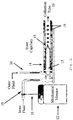
- FIG. 2 provides an inner tube 10 through which the inner fluid flows. This tube 10 is fastened to an armature 11 of a mechanical vibrator 12 that creates mechanical perturbations of the flow of fluid through tube 10.
- the inner fluid in tube 10 flows into an inner channel of capillary system 14.
- an outer fluid flows through a tube 16 into an outer channel of capillary system.
- the forked areas where tubes 10, 16 contact the capillary system 12 schematically represent the stubs of syringe needles that are used for connecting the device with syringes for injecting the fluids. Even though the details are not shown, they are arranged so that fluid in tube 10 goes to the inner part of capillary system 14 and fluid in tube 16 goes to the outer part.
- the inner phase fluid is positioned within the outer phase fluid to form the emulsion at the tip of inner capillary 15.
- the tube 10 transporting the inner phase fluid is subject to mechanical perturbations by vibrator 12 prior to its drops being encapsulated by the outer fluid. The result is the generation of encapsulated drops 19 at the output of the inner capillary 15 of capillary system 14. These drops are directed to a collection tube 18.
- the controlled droplets of the present invention are micrometer in scale and are formed by the applied perturbation of the tube 10.
- the inner capillary apparatus 15 is made up of two coaxially aligned capillary tubes.
- the inner capillary tube is cylindrical, with a tip of approximately 30 ⁇ m.
- the outer capillary is square, with an inner dimension of 1 mm.
- the coaxial alignment of the capillaries is ensured by matching the outer diameter of the inner capillary to the inner dimension of the square capillary.
- the two flexible tubes 10, 16 bring the inner and outer fluids in the capillaries at the flow rates Qin and Qout, respectively.
- PEG polyethylene glycol
- the droplets produced by the present invention have a narrow size distribution, with a typical polydispersity of less than 5%.
- a 15wt% dextran solution is injected through apparatus 10 as the inner fluid
- a 8% PEG solution is injected through apparatus 16 as the outer fluid.
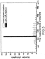
- the inner fluid is perturbed by a mechanical vibrator at a frequency of 5 Hz, and the resultant droplets 19 has a polydispersity of 3% in diameter, statistically measured in FIG.5 ,
- droplets produced without perturbing the inner fluid have a broad size distribution, with a size polydispersity of 16%.
- the mechanical vibrator 12 connected to the tube 10 agitates the inner fluid.
- the vibrator is controlled by an external generator that tunes the frequency in the range [0.1; 5000] Hz with a sinusoidal variation.
- the lack of vibration of the tip or outlet of the inner capillary 15 ensures that the effect induced by the mechanical vibrator 12 is only due to variations of the pressure at the imposed frequency.
- the apparatus enables precise control of the frequency of the pressure perturbation, which allows for precise control over the dimensions of the droplets 19 and their characteristics, given a specific flow rate of the outer and inner phases.
- flexible tube 10 directs the inner fluid into a capillary microfluidic device (not shown) which is connected to a mechanical vibrator that induces a controlled pressure variation at the entrance of the inner capillary 15.
- a microcapillary device for double emulsion generation is used to obtain simple emulsions.
- a mechanical vibrator is connected to the tubing for injecting the inner fluid. By tuning the frequency of perturbation as well as the flow rates of the different phases, all-aqueous double emulsions with different size can be obtained and the number of encapsulated droplets can be controlled (See also FIG. 6 ).
- the polydispersity of the resultant droplets is less than 5%.
- the interfacial tension between the two phases is low, about 0.7 mN/m..
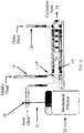
- the microfluidic device of FIG. 4 is similar to the device of FIG. 2 , but accommodates a middle fluid so as to be capable of forming W/W/W double emulsion.
- the device includes at least two coaxially aligned capillary tubes 10, 16 (as see in FIG. 2 ). Additionally, a cylindrical inner capillary 15, with an approximate tip diameter of 30 ⁇ m, is coaxially inserted in a square outer capillary, with an inner dimension of 1 mm.
- the two flexible tubings bring the inner and outer (or middle) fluids into the capillaries at the flow rates Qin and Qout, respectively.
- a mechanical vibrator 12 (such as PASCO Model SF-9324) is connected to the tubing 10 which injects the inner fluid. The vibrator is controlled by an external generator for tuning the frequency in the range of 0.1 to 5000 Hz with a sinusoidal waveform. By tuning the frequency of perturbation, a monodisperse emulsion is obtained as seen in FIG 2 .
- f 3 Hz
- f 4 Hz
- f 6 Hz
- the interfacial tension between the two phases is 1.2 mN/m.
- the fabrication of controlled W/W (water/water) emulsions can be adapted for the formation of W/W/W double emulsion using a modified glass microcapillary device 14'.
- the double emulsion is made of two or more immiscible phases with a low interfacial tension.
- the number of encapsulated droplets as well as the size of the outer and inner droplets can be controlled by adjusting the different flow rates as well as the frequency of the mechanical vibrator.
- an aqueous PEG solution forms the middle phase introduced to the capillary device 14' through tube 16
- aqueous dextran solution forms both the inner phase from inner fluid introduced through tube 10 and outer phases from outer fluid introduced to capillary device 14' through tube 20.
- the mechanical vibrator 12 is connected to the inner plastic tubing 10 as in the formation of simple W/W emulsion. By tuning the frequency and the amplitude of pressure perturbation as well as the flow rates of both phases, control can be exercised over the size for the inner droplets and the number of the inner droplets encapsulated in the middle fluid as demonstrated in FIG. 6 .
- an additional mechanical vibrator (not shown) is coupled to the tubing 16 directing the middle phase liquid. The use of two perturbations allows for the generation of double emulsions whose properties can be defined as a function of flow rate and vibration frequency.
- the present invention provides a method of using mechanical perturbations to form both water-in-water and water-in-water-in-water emulsions.
- the method described provides an advantage in generating all-aqueous emulsions by broadening the range of droplets that the microfluidic techniques typically can generate from oil-water-based liquid-liquid systems to all-aqueous systems.
- the present invention achieves the generation of the droplets by applying the perturbations to the tubing in which the fluids for injection into the devices flow, without modifying the design of the devices currently used in the art. Therefore, the approach provided by the present method and apparatus are configured to be easily incorporated into current droplet mass production devices.
- FIG. 7 is a schematic of the setup for the generation of a double emulsion in a microfluidic device.
- the flexible tubing 15 directs the inner fluid 30 into the capillary microfluidic device 14' and is connected to a mechanical vibrator (not shown) that induces controlled pressure variation at the entrance of the inner capillary.
- An additional vibrator is used to provide pressure variation for the middle fluid 33 to achieve controlled generation of double emulsion drops 31 located within the outer fluid 35.
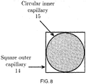
- the relative orientations of the square outer capillary (tubing) 14 relative to the circular inner capillary (tubing) 15 is such that the fluid flow is not impeded through the outer capillary.
- the dimensions of both the inner and outer capillaries can be optimized to allow the maximum amount of inner fluid relative to the outer fluid.
- a single emulsion may first be produced by mechanical vibration, followed by triggering a third phase inside the single emulsion.
- the third phase could be triggered by extracting water from the inner fluid that contains two or multiple incompatible solutes. Therefore, when the concentration of the incompatible solutes increases upon extraction of water, the originally miscible inner fluid separates into one or more immiscible phase(s).
- the apparatus of FIG. 9 shows this.
- a fluid injector 40 injects the outer fluid into tube 16, which in turn injects it into the capillary system 14 of the microfluidic device.
- FIG. 9B The details of this embodiment of the capillary system 14 are shown in FIG. 9B .
- a second fluid injector 42 injects the inner fluid into tube 10, which is subject to vibrations by mechanical vibrator 12, typically in sinusoidal fashion as shown in FIG. 9A .
- Fluid in tube 10 enters the capillary system 14 as the inner fluid as shown in FIG. 9B .
- the interfacial tension between the two phases is as low as 0.1 mN/m.
- the inner fluid phase breaks up into a single emulsion, with a polydispersity of only 3%.
- the inner phase loses water and separates a liquid core from the original single emulsion.
- the polydispersity of the double emulsion is around 6%.
- the schematic in FIG. 9B illustrates the formation of a double emulsion by inducing a phase separation inside the single emulsion template.
- the third phase could also be triggered by forcing an outer fluid solution that contains charged solutes or macromolecules to migrate into the inner fluid under an electrical field (e.g. D.C.), as shown in FIG. 8 .
- the inner phase is 10 wt % PEG solution
- the inner and outer phase fluids, with an interfacial tension of around 0.5mN/m, are oppositely charged by connecting the structures 46, 48 of the capillary system 14 for each fluid to a direct current power supply 42 set at 200 volts.
- dextran sulfate in the outer phase migrates into the inner phase under the electrostatic force, forming an immiscible phase inside the PEG solution.
- the inner phase of the PEG solution breaks up with the triggered phase and forms double emulsion, shown schematically in FIG. 8 .
- the all-aqueous emulsions can be used as liquid templates to synthesize materials with controllable sizes, such as particles and capsules.
- the size of these particles and microspheres depends on the size of the emulsion.
- the methods to synthesize these materials include evaporation of water solvent, polymerization of monomer solutions, or gelation of the liquid phases.
- the continuous phase could be water with 15wt% potassium phosphate.
- the flow rate of the emulsion phase and continuous phases could be 20 ul/h and 1000 ⁇ l/h, respectively.
- emulsion droplets When the perturbation frequency of the emulsion phase is 4 Hz, emulsion droplets with a diameter of 138 ⁇ m form. By irradiating these droplets with ultraviolet light of appropriate wavelength (e.g. 255nm) for a certain period of time (e.g. 10 seconds), the emulsion drops solidify into hydrogel particles with a diameter dictated by that of the emulsion droplet precursors.
- Capsules with controllable sizes can be fabricated by solidifying or gelating the shell phase of W/W/W double emulsions generated using this invention.
- the middle phase could be PEGDA, or other hydrogels, and the emulsion and continuous phases could be water with dextran.
- the size of the capsule depends on the dimension of the double emulsion.
- a method according to another aspect of the invention allows for the measurement of the frequency of vibrations that created a particular emulsion.
- the mechanical vibrator is replaced with a vibrating source 12' whose vibration is to be detected.
- the flow rate of the inner flow is larger and the interface forms a diverging profile, by observing the deformation of the interface, it is possible to determine the perturbation that is applied to the inner flow.
- Interfacial tension is important in this method because higher interfacial tension will suppress the deformation, while lower interfacial tension helps to magnify the perturbation and gives larger deformation.
- the interface is shown in FIG. 12 , where the scale bar is 100 ⁇ m.
- the inner fluid flows out from the nozzle and meets the outer fluid, which flows in the square capillary. (The wall of square outer capillary is not shown in FIG. 12 .)
- the flow of the two fluids forms the interface.
- the interface deforms and provides regular ripples.
- the perturbation is manifested in the emulsion.
- the corresponding frequency of the perturbation can be measured on the interface.
- the agreement between the applied and measured frequencies confirms that the perturbation is indeed the source of the ripples on the interface.
- the observed frequency can easily be measured and/or set using image analysis.
- the diameter of the device's nozzle is 45 ⁇ m, and the square outer capillary's dimension is 1mm ⁇ 1mm.
- a perturbation whose frequency is 500 Hz is applied to the inner tube.
- the perturbation that is applied to the tubing with a low interfacial tension system is manifested in the emulsion.
Landscapes
- Chemical & Material Sciences (AREA)
- Chemical Kinetics & Catalysis (AREA)
- Engineering & Computer Science (AREA)
- Materials Engineering (AREA)
- Organic Chemistry (AREA)
- Physics & Mathematics (AREA)
- General Physics & Mathematics (AREA)
- Colloid Chemistry (AREA)
- Manufacturing Of Micro-Capsules (AREA)
Claims (13)
- Verfahren zum Herstellen einer einfachen Emulsion, die zwei verschiedene nicht mischbare fluide Phasen mit einer niedrigen Grenzflächenspannung mit einem hohen Grad an Gleichförmigkeit enthält, unter Verwendung einer mikrofluidischen Vorrichtung (14), die konzentrische Kapillaren aufweist, umfassend die folgenden Schritte:Einleiten eines Außenphasenfluids durch einen Schlauch (16) in eine äußere Kapillare der mikrofluidischen Vorrichtung;Einführen eines Innenphasenfluids durch einen flexiblen Schlauch (10) in eine innere Kapillare (15) der mikrofluidischen Vorrichtung, wobei das innere Fluid an einem Auslass der inneren Kapillare in das äußere Fluid in der mikrofluidischen Vorrichtung (14) eingespritzt wird; gekennzeichnet durchmechanisches Vibrieren des flexiblen Schlauchs (10), der das Innenphasenfluid in die mikrofluidische Vorrichtung (14) bringt, um darin eine Druckstörung zu erzeugen, wodurch an dem Ausgang der mikrofluidischen Vorrichtung (14) eingekapselte Tropfen (19) gebildet werden, wobei der flexible Schlauch (10) vor dem Ausgang vibriert wird, ohne den Ausgang zu vibrieren.
- Verfahren zum Herstellen einer einfachen Emulsion, die zwei verschiedene nicht mischbare fluide Phasen enthält, wie es in Anspruch 1 beansprucht ist, wobei sowohl das innere als auch das äußere Fluid wässrige Phasen sind.
- Verfahren zum Herstellen einer doppelten Emulsion, die zwei oder mehrere nicht mischbare Phasen mit einer niedrigen Grenzflächenspannung und einem hohen Grad an Gleichförmigkeit enthält, unter Verwendung einer mikrofluidischen Vorrichtung (14'), die konzentrische Kapillaren aufweist, umfassend die folgenden Schritte:Einleiten eines Außenphasenfluids (35) durch einen Schlauch (20) in eine äußere Kapillare der mikrofluidischen Vorrichtung;Einleiten eines Innenphasenfluids (30) durch einen flexiblen Schlauch (10) in eine innere Kapillare (15) der mikrofluidischen Vorrichtung;Einführen eines Mittelphasenfluids (33) durch einen Schlauch (16) in eine mittlere Kapillare der mikrofluidischen Vorrichtung, wobei das innere Fluid (30) an einem Auslass der inneren Kapillare in das mittlere Fluid (33) in der mikrofluidischen Vorrichtung eingespritzt wird und das Resultat des kombinierten inneren und mittleren Fluids in das äußere Fluid (35) in der mikrofluidischen Vorrichtung (14') eingespritzt wird;gekennzeichnet durch mechanisches Vibrieren des flexiblen Schlauchs (10), der das Innenphasenfluid (30) in die mikrofluidische Vorrichtung (14') bringt, um darin eine Druckstörung zu erzeugen, wodurch am Ausgang der mikrofluidischen Vorrichtung (14') doppelt eingekapselte Tropfen (31) gebildet werden, wobei der flexible Schlauch (10) vor dem Auslass vibriert wird, ohne den Auslass zu vibrieren.
- Verfahren zum Herstellen einer doppelten Emulsion, die zwei oder mehrere nicht mischbare Phasen enthält, wie es in Anspruch 3 beansprucht ist, wobei das innere (30), das äußere (35) und das mittlere (33) Fluid wässrige Phasen sind.
- Verfahren zum Herstellen einer doppelten Emulsion, die zwei oder mehrere nicht mischbare Phasen enthält, wie es in Anspruch 3 beansprucht ist, wobei der Schlauch (16), der das mittlere Fluid (33) in die mikrofluidische Vorrichtung (14') bringt, flexibel ist und ferner umfassend den folgenden Schritt:
Vibrieren des Schlauchs (16), der die mittlere Flüssigkeit (33) in die mikrofluidische Vorrichtung (14') zuführt. - Vorrichtung zum Herstellen einer vollwässrigen doppelten Emulsion, die zwei oder mehrere nicht mischbare wässrige Phasen enthält, umfassend:eine mikrofluidische Vorrichtung (14');eine äußere Fluidkapillare, eine innere Fluidkapillare (15), die sich innerhalb der äußeren Fluidkapillare der mikrofluidischen Vorrichtung befindet, und ferner konfiguriert ist, um Fluid (30) durch einen Auslass in die äußere Fluidkapillare zu leiten;einen flexiblen Schlauch (10), der mit der inneren Kapillare (15) gekoppelt ist, um das innere Fluid (30) darin einzuleiten; gekennzeichnet durcheinen mechanischen Vibrator (12), wobei der mechanische Vibrator konfiguriert ist, um den flexiblen Schlauch (10) an einem Punkt vor dem Auslass mechanisch zu stören, ohne den Auslass zu vibrieren.
- Vorrichtung zum Herstellen einer vollwässrigen doppelten Emulsion nach Anspruch 6, wobei:
eine mittlere Fluidkapillare zwischen der inneren und der äußeren Kapillare angeordnet ist, wobei die mittlere Fluidkapillare konfiguriert ist, sodass Fluid (30), das durch den inneren Kapillarauslass geleitet wird, in einen mittleren Kapillareinlass geleitet wird, sodass inneres Fluid (30) von dem mittleren Fluid (33) eingekapselt ist und das mittlere Fluid von dem äußeren Fluid (35) eingekapselt ist. - Vorrichtung zum Herstellen einer vollwässrigen doppelten Emulsion nach Anspruch 7, ferner umfassend einen Schlauch (16), der mit der mittleren Kapillare gekoppelt ist, um das mittlere Fluid (33) in diese einzuführen, wobei ein zweiter mechanischer Vibrator mit dem Schlauch (16) verbunden ist.
- Vorrichtung nach Anspruch 6, ferner umfassend:
einen Flüssigkeitsextraktor, der eine dritte Phase innerhalb der einzelnen Emulsion auslöst, wenn das innere Fluid (30) zwei oder mehrere inkompatible gelöste Stoffe enthält, indem er Wasser aus der inneren Flüssigkeit (30) extrahiert, sodass die Konzentration der inkompatiblen gelösten Stoffe ansteigt, bis sich das innere Fluid in eine oder mehrere nicht mischbare Phasen trennt. - Vorrichtung nach Anspruch 9, wobei das innere Fluid (30) ein Gemisch aus etwa 5 Gewichtsprozent Dextran (Mw=500.000) und etwa 1 % PEG (Mw=8000) ist, und das äußere Fluid (35) etwa 8 Gewichtsprozent PEG (Mw=8000) ist.
- Verfahren zum Herstellen einer vollwässrigen doppelten Emulsion, die zwei oder mehrere nicht mischbare wässrige Phasen enthält, in einer mikrofluidischen Vorrichtung (14; 14'), dadurch gekennzeichnet, dass es die folgenden Schritte umfasst:Vibrieren eines oder mehrerer flexibler Schläuche (10, 16, 20), die eines der Wässrigphasenfluide (30, 33, 35) in die Vorrichtung (14; 14') zuführen, um eine Druckstörung zu erzeugen, wodurch eine einzelne Emulsion geschaffen wird;und Auslösen einer dritten Phase innerhalb der einzelnen Emulsion durch Extrahieren von Wasser aus dem inneren Fluid (30), wenn es zwei oder mehrere inkompatible gelöste Stoffe enthält, sodass die Konzentration der inkompatiblen gelösten Stoffe ansteigt, bis sich das innere Fluid (30) in zwei oder mehrere nicht mischbare Phasen trennt.
- Vorrichtung zur Herstellung einer doppelten Emulsion, die zwei oder mehrere nicht mischbare wässrige Phasen enthält, umfassend:eine mikrofluidische Vorrichtung (14');eine äußere Fluidkapillare, eine innere Fluidkapillare (15), die sich innerhalb der äußeren Fluidkapillare der mikrofluidischen Vorrichtung befindet, und ferner konfiguriert ist, um Fluid durch einen Auslass in die äußere Fluidkapillare zu leiten;einen flexiblen Schlauch (10), der mit der inneren Kapillare (15) gekoppelt ist, um das innere Fluid (30) darin einzuleiten;gekennzeichnet durch einen mechanischen Vibrator (12), wobei der mechanische Vibrator konfiguriert ist, um den flexiblen Schlauch (10) an einem Punkt vor dem Auslass mechanisch zu stören, ohne den Auslass zu vibrieren; undeine Stromversorgung, die das innere (30) und das äußere (35) Fluid entgegengesetzt auflädt, sodass das äußere Fluid (35) unter elektrostatischer Kraft in das innere Fluid (30) wandert und eine nicht mischbare Phase innerhalb des äußeren Fluids bildet.
- Vorrichtung nach Anspruch 12, wobei das innere Fluid (30) eine PEG-Lösung von etwa 10 Gewichtsprozent ist und das äußere Fluid (35) ein Gemisch aus eine Lösung von etwa 10 Gewichtsprozent Dextran (Mw=500.000) und etwa 10 Gewichtsprozent Dextransulfat (Mw=500.000) ist, und wobei die Stromversorgung auf etwa 200 Volt eingestellt ist, wodurch das Vibrieren des Schlauchs (20) der äußeren Phase (35) bewirkt, dass die innere Phase (30) der PEG-Lösung mit der ausgelösten Phase aufbricht und eine Doppelemulsion bildet.
Applications Claiming Priority (2)
| Application Number | Priority Date | Filing Date | Title |
|---|---|---|---|
| US201261611886P | 2012-03-16 | 2012-03-16 | |
| PCT/CN2013/072806 WO2013135211A1 (en) | 2012-03-16 | 2013-03-18 | System and method for generation of emulsions with low interfacial tension and measuring frequency vibrations in the system |
Publications (3)
| Publication Number | Publication Date |
|---|---|
| EP2825155A1 EP2825155A1 (de) | 2015-01-21 |
| EP2825155A4 EP2825155A4 (de) | 2016-04-13 |
| EP2825155B1 true EP2825155B1 (de) | 2021-03-17 |
Family
ID=49160264
Family Applications (1)
| Application Number | Title | Priority Date | Filing Date |
|---|---|---|---|
| EP13760719.8A Active EP2825155B1 (de) | 2012-03-16 | 2013-03-18 | System und verfahren zur erzeugung von emulsionen mit geringer zwischenflächenspannung |
Country Status (4)
| Country | Link |
|---|---|
| US (2) | US10080997B2 (de) |
| EP (1) | EP2825155B1 (de) |
| CN (2) | CN104284654A (de) |
| WO (1) | WO2013135211A1 (de) |
Families Citing this family (20)
| Publication number | Priority date | Publication date | Assignee | Title |
|---|---|---|---|---|
| CN105979938A (zh) * | 2013-12-09 | 2016-09-28 | 香港大学 | 用于包封粒子、胶体和细胞的芯-壳胶囊 |
| CN110075308B (zh) * | 2013-12-09 | 2023-05-23 | 港大科桥有限公司 | 稳定化的全水乳液及其制备和使用方法 |
| CN103721655B (zh) * | 2014-01-06 | 2015-12-09 | 武汉理工大学 | 一种尺寸均一且大小可控的壳聚糖微胶囊的制备方法 |
| CN104084247B (zh) * | 2014-06-30 | 2017-02-08 | 北京工业大学 | 基于t形微通道的弹性壁面微流控芯片 |
| CN106622407A (zh) * | 2016-09-29 | 2017-05-10 | 东南大学 | 一种用于固体内核包裹的毛细管微流控装置及制备方法 |
| CN106540638A (zh) * | 2016-11-25 | 2017-03-29 | 复旦大学 | 一种基于液滴微/毫流控技术制备胶囊的方法 |
| CN107029640B (zh) * | 2017-05-23 | 2023-04-21 | 中国科学技术大学 | 基于液驱流动聚焦射流扰动的微液滴主动制备装置及方法 |
| CN109647547A (zh) * | 2017-10-12 | 2019-04-19 | 中国科学院大连化学物理研究所 | 一种基于微流控技术的可控双水相液滴的制备方法 |
| CN107638836B (zh) * | 2017-11-09 | 2023-10-03 | 东南大学 | 一种多重乳液制备系统 |
| CN108465447B (zh) * | 2018-06-05 | 2024-01-23 | 扬州大学 | 多层微胶囊异形化装置、制备装置及制备方法 |
| FR3085121B1 (fr) * | 2018-08-23 | 2020-11-20 | Capsum | Dispositif de production d'une dispersion, ensemble et procede associes |
| TR201818352A2 (tr) * | 2018-12-02 | 2020-06-22 | Bursa Teknik Ueniversitesi | Mi̇kroenkapsülasyon yöntemleri̇nde parti̇kül boyutunu küçülten damlatma düzeneği̇ |
| US11860076B2 (en) * | 2019-06-20 | 2024-01-02 | Vilnius University | Systems and methods for encapsulation and multi-step processing of biological samples |
| GB2610116A (en) * | 2020-02-18 | 2023-02-22 | Bennubio Inc | Method and apparatus for large-scale spheroid generation |
| CN113403697B (zh) * | 2021-07-29 | 2022-05-27 | 南京鼓楼医院 | 一种可编程仿蛛丝纤维及其制备方法 |
| CN113499697B (zh) * | 2021-08-04 | 2022-07-26 | 西南交通大学 | 一种水包水包水单分散双重乳液及其制备方法 |
| CN113604344B (zh) * | 2021-08-11 | 2024-03-22 | 北京慧智医疗器械有限公司 | 一种高通量一体式微液滴数字pcr的实现系统 |
| CN116060143B (zh) * | 2022-09-08 | 2025-12-12 | 浙江大学 | 基于双矩形通道毛细管的液滴尺寸可调节的液滴制备装置 |
| CN117443470A (zh) * | 2023-10-08 | 2024-01-26 | 浙江万里学院 | 一种脂质体的微流控制备装置及制备方法 |
| NL2038460B1 (en) | 2024-08-19 | 2026-03-02 | Univ Twente | On-chip microfluidics |
Family Cites Families (24)
| Publication number | Priority date | Publication date | Assignee | Title |
|---|---|---|---|---|
| GB1502561A (en) * | 1977-01-05 | 1978-03-01 | Nat Res Dev | Solvent extraction of copper between organic and aqueous phases |
| US5175093A (en) * | 1989-11-07 | 1992-12-29 | Lehigh University | Bioactive cells immobilized in alginate beads containing voids formed with polyethylene glycol |
| JP3361131B2 (ja) * | 1992-11-18 | 2003-01-07 | フロイント産業株式会社 | シームレスカプセル製造装置 |
| US6248378B1 (en) * | 1998-12-16 | 2001-06-19 | Universidad De Sevilla | Enhanced food products |
| CA2365847A1 (en) * | 1999-04-06 | 2000-10-12 | Gregg M. Duthaler | Methods for producing droplets for use in capsule-based electrophoretic displays |
| US7393501B2 (en) * | 2002-05-29 | 2008-07-01 | Nano Vibronix Inc | Method, apparatus and system for treating biofilms associated with catheters |
| CN101115468A (zh) * | 2002-06-03 | 2008-01-30 | 金拓 | 用于结构易变的试剂的无副作用微囊包封技术及水相-水相乳剂的应用 |
| JP2006507921A (ja) * | 2002-06-28 | 2006-03-09 | プレジデント・アンド・フェロウズ・オブ・ハーバード・カレッジ | 流体分散のための方法および装置 |
| WO2005021151A1 (en) * | 2003-08-27 | 2005-03-10 | President And Fellows Of Harvard College | Electronic control of fluidic species |
| JP2005077219A (ja) * | 2003-08-29 | 2005-03-24 | Fuji Photo Film Co Ltd | マイクロデバイスの流体混合反応促進方法及びマイクロデバイス |
| WO2006051153A2 (en) * | 2004-11-09 | 2006-05-18 | Nanolab Systems Oy | Methods and devices for facile fabrication of nanoparticles and their applications |
| WO2006096571A2 (en) * | 2005-03-04 | 2006-09-14 | President And Fellows Of Harvard College | Method and apparatus for forming multiple emulsions |
| US20090306231A1 (en) * | 2006-05-15 | 2009-12-10 | Satish Venkata Akella | Process for preparing an emulsion |
| WO2008044459A1 (en) * | 2006-10-11 | 2008-04-17 | Freund Corporation | Apparatus for manufacturing seamless capsule |
| EP2136786B8 (de) * | 2007-03-28 | 2012-11-14 | President and Fellows of Harvard College | Vorrichtung zur Formung von Tröpfchen |
| JP5262064B2 (ja) * | 2007-10-30 | 2013-08-14 | 富士ゼロックス株式会社 | マイクロリアクターを用いた反応方法及びマイクロリアクター |
| EP2303246A1 (de) * | 2008-06-05 | 2011-04-06 | President and Fellows of Harvard College | Polymersome, kolloidosome, liposome und andere spezies im zusammenhang mit fluidtröpfchen |
| FR2937884A1 (fr) * | 2008-11-05 | 2010-05-07 | Osmooze | Procede de formation d'une emulsion a partir de liquides non miscibles en eux et application a l'alimentation en liquide d'un dispositif de nebulisation |
| WO2010148106A1 (en) * | 2009-06-16 | 2010-12-23 | Washington State University Research Foundation | Systems and methods involving calcium phosphate based materials |
| CN102483424B (zh) * | 2009-06-26 | 2014-11-05 | 哈佛学院院长等 | 用于流体操作的方法以及微流体装置 |
| ES2533498T3 (es) * | 2009-08-28 | 2015-04-10 | Georgia Tech Research Corporation | Método y dispositivo electro-fluídico para producir emulsiones y suspensión de partículas |
| US20110223314A1 (en) * | 2010-03-10 | 2011-09-15 | Xiaoxiao Zhang | Efficient microencapsulation |
| JP5858451B2 (ja) * | 2010-06-29 | 2016-02-10 | 国立大学法人 岡山大学 | ヒドロゲルカプセルの製造方法 |
| US9695390B2 (en) * | 2010-08-23 | 2017-07-04 | President And Fellows Of Harvard College | Acoustic waves in microfluidics |
-
2013
- 2013-03-15 US US13/839,072 patent/US10080997B2/en active Active
- 2013-03-18 CN CN201380014220.3A patent/CN104284654A/zh active Pending
- 2013-03-18 CN CN202010205853.4A patent/CN111521525A/zh active Pending
- 2013-03-18 WO PCT/CN2013/072806 patent/WO2013135211A1/en not_active Ceased
- 2013-03-18 EP EP13760719.8A patent/EP2825155B1/de active Active
-
2018
- 2018-08-22 US US16/109,626 patent/US11154824B2/en active Active
Non-Patent Citations (1)
| Title |
|---|
| None * |
Also Published As
| Publication number | Publication date |
|---|---|
| US11154824B2 (en) | 2021-10-26 |
| EP2825155A1 (de) | 2015-01-21 |
| EP2825155A4 (de) | 2016-04-13 |
| US20180361328A1 (en) | 2018-12-20 |
| WO2013135211A1 (en) | 2013-09-19 |
| CN111521525A (zh) | 2020-08-11 |
| US20130274353A1 (en) | 2013-10-17 |
| US10080997B2 (en) | 2018-09-25 |
| CN104284654A (zh) | 2015-01-14 |
Similar Documents
| Publication | Publication Date | Title |
|---|---|---|
| EP2825155B1 (de) | System und verfahren zur erzeugung von emulsionen mit geringer zwischenflächenspannung | |
| US11141731B2 (en) | Formation and control of fluidic species | |
| JP5841937B2 (ja) | 流体注入 | |
| Ziemecka et al. | All-aqueous core-shell droplets produced in a microfluidic device | |
| Zhu et al. | Free‐boundary microfluidic platform for advanced materials manufacturing and applications | |
| Davies et al. | Formation of liposomes using a 3D flow focusing microfluidic device with spatially patterned wettability by corona discharge | |
| Karyappa et al. | Electroemulsification in a uniform electric field | |
| Montanero et al. | Tip Streaming of Simple and Complex Fluids | |
| EP3187252A1 (de) | Verfahren und vorrichtung zur herstellung einfacher und zusammengesetzter emulsionen im mikrometergrössenbereich | |
| Tan et al. | Controlled fission of droplet emulsion in bifurcating microfluidic channels | |
| AU2018204623B2 (en) | Fluid injection | |
| Jeyhani | Controlled Formation of Oil-Free Soft Biomaterials Using All-Aqueous Fluid Systems | |
| Arjanaki et al. | Experimental investigation of surfactant influence on the viscoelastic coaxial electrospray | |
| Minardi et al. | Reagent delivery by partial coalescence and noncoalescence of aqueous microdroplets in oil | |
| Kothandaraman | Experimental and computational analysis of bubble generation combining oscillating fields and microfluidics | |
| Cheng et al. | Microdroplets Produced Through an AC Electrospraying Method in Microfluidic Channels | |
| Link et al. | Formation and Control of Fluidic Species | |
| Utada | Drop formation in multi-phase microfluidic flows |
Legal Events
| Date | Code | Title | Description |
|---|---|---|---|
| PUAI | Public reference made under article 153(3) epc to a published international application that has entered the european phase |
Free format text: ORIGINAL CODE: 0009012 |
|
| 17P | Request for examination filed |
Effective date: 20140805 |
|
| AK | Designated contracting states |
Kind code of ref document: A1 Designated state(s): AL AT BE BG CH CY CZ DE DK EE ES FI FR GB GR HR HU IE IS IT LI LT LU LV MC MK MT NL NO PL PT RO RS SE SI SK SM TR |
|
| AX | Request for extension of the european patent |
Extension state: BA ME |
|
| DAX | Request for extension of the european patent (deleted) | ||
| RIC1 | Information provided on ipc code assigned before grant |
Ipc: B01F 13/00 20060101ALI20151021BHEP Ipc: B01F 3/08 20060101ALI20151021BHEP Ipc: B01F 17/00 20060101ALI20151021BHEP Ipc: G01H 3/04 20060101ALI20151021BHEP Ipc: B01F 15/02 20060101ALI20151021BHEP Ipc: A61K 9/113 20060101AFI20151021BHEP |
|
| RA4 | Supplementary search report drawn up and despatched (corrected) |
Effective date: 20151106 |
|
| RIC1 | Information provided on ipc code assigned before grant |
Ipc: G01H 3/04 20060101ALI20151102BHEP Ipc: B01F 15/02 20060101ALI20151102BHEP Ipc: A61K 9/113 20060101AFI20151102BHEP Ipc: B01F 13/00 20060101ALI20151102BHEP Ipc: B01F 17/00 20060101ALI20151102BHEP Ipc: B01F 3/08 20060101ALI20151102BHEP |
|
| DA4 | Supplementary search report drawn up and despatched (deleted) | ||
| RA4 | Supplementary search report drawn up and despatched (corrected) |
Effective date: 20160316 |
|
| RIC1 | Information provided on ipc code assigned before grant |
Ipc: B01F 3/08 20060101ALI20160310BHEP Ipc: A61K 9/113 20060101AFI20160310BHEP Ipc: B01F 15/02 20060101ALI20160310BHEP Ipc: G01H 3/04 20060101ALI20160310BHEP Ipc: B01F 17/00 20060101ALI20160310BHEP Ipc: B01F 13/00 20060101ALI20160310BHEP |
|
| RAP1 | Party data changed (applicant data changed or rights of an application transferred) |
Owner name: VERSITECH LIMITED |
|
| STAA | Information on the status of an ep patent application or granted ep patent |
Free format text: STATUS: EXAMINATION IS IN PROGRESS |
|
| 17Q | First examination report despatched |
Effective date: 20190403 |
|
| GRAP | Despatch of communication of intention to grant a patent |
Free format text: ORIGINAL CODE: EPIDOSNIGR1 |
|
| STAA | Information on the status of an ep patent application or granted ep patent |
Free format text: STATUS: GRANT OF PATENT IS INTENDED |
|
| GRAS | Grant fee paid |
Free format text: ORIGINAL CODE: EPIDOSNIGR3 |
|
| GRAA | (expected) grant |
Free format text: ORIGINAL CODE: 0009210 |
|
| STAA | Information on the status of an ep patent application or granted ep patent |
Free format text: STATUS: THE PATENT HAS BEEN GRANTED |
|
| INTG | Intention to grant announced |
Effective date: 20210120 |
|
| AK | Designated contracting states |
Kind code of ref document: B1 Designated state(s): AL AT BE BG CH CY CZ DE DK EE ES FI FR GB GR HR HU IE IS IT LI LT LU LV MC MK MT NL NO PL PT RO RS SE SI SK SM TR |
|
| REG | Reference to a national code |
Ref country code: GB Ref legal event code: FG4D |
|
| REG | Reference to a national code |
Ref country code: CH Ref legal event code: EP |
|
| REG | Reference to a national code |
Ref country code: DE Ref legal event code: R096 Ref document number: 602013076321 Country of ref document: DE |
|
| REG | Reference to a national code |
Ref country code: IE Ref legal event code: FG4D |
|
| REG | Reference to a national code |
Ref country code: AT Ref legal event code: REF Ref document number: 1371579 Country of ref document: AT Kind code of ref document: T Effective date: 20210415 |
|
| REG | Reference to a national code |
Ref country code: LT Ref legal event code: MG9D |
|
| PG25 | Lapsed in a contracting state [announced via postgrant information from national office to epo] |
Ref country code: HR Free format text: LAPSE BECAUSE OF FAILURE TO SUBMIT A TRANSLATION OF THE DESCRIPTION OR TO PAY THE FEE WITHIN THE PRESCRIBED TIME-LIMIT Effective date: 20210317 Ref country code: FI Free format text: LAPSE BECAUSE OF FAILURE TO SUBMIT A TRANSLATION OF THE DESCRIPTION OR TO PAY THE FEE WITHIN THE PRESCRIBED TIME-LIMIT Effective date: 20210317 Ref country code: GR Free format text: LAPSE BECAUSE OF FAILURE TO SUBMIT A TRANSLATION OF THE DESCRIPTION OR TO PAY THE FEE WITHIN THE PRESCRIBED TIME-LIMIT Effective date: 20210618 Ref country code: BG Free format text: LAPSE BECAUSE OF FAILURE TO SUBMIT A TRANSLATION OF THE DESCRIPTION OR TO PAY THE FEE WITHIN THE PRESCRIBED TIME-LIMIT Effective date: 20210617 Ref country code: NO Free format text: LAPSE BECAUSE OF FAILURE TO SUBMIT A TRANSLATION OF THE DESCRIPTION OR TO PAY THE FEE WITHIN THE PRESCRIBED TIME-LIMIT Effective date: 20210617 |
|
| REG | Reference to a national code |
Ref country code: AT Ref legal event code: MK05 Ref document number: 1371579 Country of ref document: AT Kind code of ref document: T Effective date: 20210317 |
|
| REG | Reference to a national code |
Ref country code: NL Ref legal event code: MP Effective date: 20210317 |
|
| PG25 | Lapsed in a contracting state [announced via postgrant information from national office to epo] |
Ref country code: SE Free format text: LAPSE BECAUSE OF FAILURE TO SUBMIT A TRANSLATION OF THE DESCRIPTION OR TO PAY THE FEE WITHIN THE PRESCRIBED TIME-LIMIT Effective date: 20210317 Ref country code: LV Free format text: LAPSE BECAUSE OF FAILURE TO SUBMIT A TRANSLATION OF THE DESCRIPTION OR TO PAY THE FEE WITHIN THE PRESCRIBED TIME-LIMIT Effective date: 20210317 Ref country code: RS Free format text: LAPSE BECAUSE OF FAILURE TO SUBMIT A TRANSLATION OF THE DESCRIPTION OR TO PAY THE FEE WITHIN THE PRESCRIBED TIME-LIMIT Effective date: 20210317 |
|
| PG25 | Lapsed in a contracting state [announced via postgrant information from national office to epo] |
Ref country code: NL Free format text: LAPSE BECAUSE OF FAILURE TO SUBMIT A TRANSLATION OF THE DESCRIPTION OR TO PAY THE FEE WITHIN THE PRESCRIBED TIME-LIMIT Effective date: 20210317 |
|
| PG25 | Lapsed in a contracting state [announced via postgrant information from national office to epo] |
Ref country code: SM Free format text: LAPSE BECAUSE OF FAILURE TO SUBMIT A TRANSLATION OF THE DESCRIPTION OR TO PAY THE FEE WITHIN THE PRESCRIBED TIME-LIMIT Effective date: 20210317 Ref country code: AT Free format text: LAPSE BECAUSE OF FAILURE TO SUBMIT A TRANSLATION OF THE DESCRIPTION OR TO PAY THE FEE WITHIN THE PRESCRIBED TIME-LIMIT Effective date: 20210317 Ref country code: CZ Free format text: LAPSE BECAUSE OF FAILURE TO SUBMIT A TRANSLATION OF THE DESCRIPTION OR TO PAY THE FEE WITHIN THE PRESCRIBED TIME-LIMIT Effective date: 20210317 Ref country code: EE Free format text: LAPSE BECAUSE OF FAILURE TO SUBMIT A TRANSLATION OF THE DESCRIPTION OR TO PAY THE FEE WITHIN THE PRESCRIBED TIME-LIMIT Effective date: 20210317 Ref country code: LT Free format text: LAPSE BECAUSE OF FAILURE TO SUBMIT A TRANSLATION OF THE DESCRIPTION OR TO PAY THE FEE WITHIN THE PRESCRIBED TIME-LIMIT Effective date: 20210317 |
|
| PG25 | Lapsed in a contracting state [announced via postgrant information from national office to epo] |
Ref country code: ES Free format text: LAPSE BECAUSE OF FAILURE TO SUBMIT A TRANSLATION OF THE DESCRIPTION OR TO PAY THE FEE WITHIN THE PRESCRIBED TIME-LIMIT Effective date: 20210317 Ref country code: PL Free format text: LAPSE BECAUSE OF FAILURE TO SUBMIT A TRANSLATION OF THE DESCRIPTION OR TO PAY THE FEE WITHIN THE PRESCRIBED TIME-LIMIT Effective date: 20210317 Ref country code: PT Free format text: LAPSE BECAUSE OF FAILURE TO SUBMIT A TRANSLATION OF THE DESCRIPTION OR TO PAY THE FEE WITHIN THE PRESCRIBED TIME-LIMIT Effective date: 20210719 Ref country code: SK Free format text: LAPSE BECAUSE OF FAILURE TO SUBMIT A TRANSLATION OF THE DESCRIPTION OR TO PAY THE FEE WITHIN THE PRESCRIBED TIME-LIMIT Effective date: 20210317 Ref country code: RO Free format text: LAPSE BECAUSE OF FAILURE TO SUBMIT A TRANSLATION OF THE DESCRIPTION OR TO PAY THE FEE WITHIN THE PRESCRIBED TIME-LIMIT Effective date: 20210317 Ref country code: IS Free format text: LAPSE BECAUSE OF FAILURE TO SUBMIT A TRANSLATION OF THE DESCRIPTION OR TO PAY THE FEE WITHIN THE PRESCRIBED TIME-LIMIT Effective date: 20210717 |
|
| REG | Reference to a national code |
Ref country code: BE Ref legal event code: MM Effective date: 20210331 |
|
| REG | Reference to a national code |
Ref country code: DE Ref legal event code: R097 Ref document number: 602013076321 Country of ref document: DE |
|
| PLBE | No opposition filed within time limit |
Free format text: ORIGINAL CODE: 0009261 |
|
| STAA | Information on the status of an ep patent application or granted ep patent |
Free format text: STATUS: NO OPPOSITION FILED WITHIN TIME LIMIT |
|
| PG25 | Lapsed in a contracting state [announced via postgrant information from national office to epo] |
Ref country code: DK Free format text: LAPSE BECAUSE OF FAILURE TO SUBMIT A TRANSLATION OF THE DESCRIPTION OR TO PAY THE FEE WITHIN THE PRESCRIBED TIME-LIMIT Effective date: 20210317 Ref country code: IE Free format text: LAPSE BECAUSE OF NON-PAYMENT OF DUE FEES Effective date: 20210318 Ref country code: AL Free format text: LAPSE BECAUSE OF FAILURE TO SUBMIT A TRANSLATION OF THE DESCRIPTION OR TO PAY THE FEE WITHIN THE PRESCRIBED TIME-LIMIT Effective date: 20210317 Ref country code: MC Free format text: LAPSE BECAUSE OF FAILURE TO SUBMIT A TRANSLATION OF THE DESCRIPTION OR TO PAY THE FEE WITHIN THE PRESCRIBED TIME-LIMIT Effective date: 20210317 Ref country code: LU Free format text: LAPSE BECAUSE OF NON-PAYMENT OF DUE FEES Effective date: 20210318 |
|
| 26N | No opposition filed |
Effective date: 20211220 |
|
| PG25 | Lapsed in a contracting state [announced via postgrant information from national office to epo] |
Ref country code: SI Free format text: LAPSE BECAUSE OF FAILURE TO SUBMIT A TRANSLATION OF THE DESCRIPTION OR TO PAY THE FEE WITHIN THE PRESCRIBED TIME-LIMIT Effective date: 20210317 |
|
| PG25 | Lapsed in a contracting state [announced via postgrant information from national office to epo] |
Ref country code: IT Free format text: LAPSE BECAUSE OF FAILURE TO SUBMIT A TRANSLATION OF THE DESCRIPTION OR TO PAY THE FEE WITHIN THE PRESCRIBED TIME-LIMIT Effective date: 20210317 |
|
| PG25 | Lapsed in a contracting state [announced via postgrant information from national office to epo] |
Ref country code: IS Free format text: LAPSE BECAUSE OF FAILURE TO SUBMIT A TRANSLATION OF THE DESCRIPTION OR TO PAY THE FEE WITHIN THE PRESCRIBED TIME-LIMIT Effective date: 20210717 |
|
| PG25 | Lapsed in a contracting state [announced via postgrant information from national office to epo] |
Ref country code: BE Free format text: LAPSE BECAUSE OF NON-PAYMENT OF DUE FEES Effective date: 20210331 |
|
| PG25 | Lapsed in a contracting state [announced via postgrant information from national office to epo] |
Ref country code: HU Free format text: LAPSE BECAUSE OF FAILURE TO SUBMIT A TRANSLATION OF THE DESCRIPTION OR TO PAY THE FEE WITHIN THE PRESCRIBED TIME-LIMIT; INVALID AB INITIO Effective date: 20130318 |
|
| PG25 | Lapsed in a contracting state [announced via postgrant information from national office to epo] |
Ref country code: CY Free format text: LAPSE BECAUSE OF FAILURE TO SUBMIT A TRANSLATION OF THE DESCRIPTION OR TO PAY THE FEE WITHIN THE PRESCRIBED TIME-LIMIT Effective date: 20210317 |
|
| PG25 | Lapsed in a contracting state [announced via postgrant information from national office to epo] |
Ref country code: MK Free format text: LAPSE BECAUSE OF FAILURE TO SUBMIT A TRANSLATION OF THE DESCRIPTION OR TO PAY THE FEE WITHIN THE PRESCRIBED TIME-LIMIT Effective date: 20210317 |
|
| PG25 | Lapsed in a contracting state [announced via postgrant information from national office to epo] |
Ref country code: TR Free format text: LAPSE BECAUSE OF FAILURE TO SUBMIT A TRANSLATION OF THE DESCRIPTION OR TO PAY THE FEE WITHIN THE PRESCRIBED TIME-LIMIT Effective date: 20210317 |
|
| PG25 | Lapsed in a contracting state [announced via postgrant information from national office to epo] |
Ref country code: MT Free format text: LAPSE BECAUSE OF FAILURE TO SUBMIT A TRANSLATION OF THE DESCRIPTION OR TO PAY THE FEE WITHIN THE PRESCRIBED TIME-LIMIT Effective date: 20210317 |
|
| PGFP | Annual fee paid to national office [announced via postgrant information from national office to epo] |
Ref country code: CH Payment date: 20250401 Year of fee payment: 13 |
|
| REG | Reference to a national code |
Ref country code: CH Ref legal event code: U11 Free format text: ST27 STATUS EVENT CODE: U-0-0-U10-U11 (AS PROVIDED BY THE NATIONAL OFFICE) Effective date: 20260401 |
|
| PGFP | Annual fee paid to national office [announced via postgrant information from national office to epo] |
Ref country code: GB Payment date: 20260202 Year of fee payment: 14 |
|
| PGFP | Annual fee paid to national office [announced via postgrant information from national office to epo] |
Ref country code: DE Payment date: 20260204 Year of fee payment: 14 |
|
| PGFP | Annual fee paid to national office [announced via postgrant information from national office to epo] |
Ref country code: FR Payment date: 20260209 Year of fee payment: 14 |