EP2825746B1 - Système d'équilibrage de rotor de turbomachine, rotor de turbomachine et procédé d'utilisation de ce système - Google Patents
Système d'équilibrage de rotor de turbomachine, rotor de turbomachine et procédé d'utilisation de ce système Download PDFInfo
- Publication number
- EP2825746B1 EP2825746B1 EP13761712.2A EP13761712A EP2825746B1 EP 2825746 B1 EP2825746 B1 EP 2825746B1 EP 13761712 A EP13761712 A EP 13761712A EP 2825746 B1 EP2825746 B1 EP 2825746B1
- Authority
- EP
- European Patent Office
- Prior art keywords
- rotor
- aft
- mounting
- weight
- circumferential array
- Prior art date
- Legal status (The legal status is an assumption and is not a legal conclusion. Google has not performed a legal analysis and makes no representation as to the accuracy of the status listed.)
- Active
Links
Images


Classifications
-
- F—MECHANICAL ENGINEERING; LIGHTING; HEATING; WEAPONS; BLASTING
- F01—MACHINES OR ENGINES IN GENERAL; ENGINE PLANTS IN GENERAL; STEAM ENGINES
- F01D—NON-POSITIVE DISPLACEMENT MACHINES OR ENGINES, e.g. STEAM TURBINES
- F01D5/00—Blades; Blade-carrying members; Heating, heat-insulating, cooling or antivibration means on the blades or the members
- F01D5/02—Blade-carrying members, e.g. rotors
- F01D5/027—Arrangements for balancing
-
- F—MECHANICAL ENGINEERING; LIGHTING; HEATING; WEAPONS; BLASTING
- F04—POSITIVE - DISPLACEMENT MACHINES FOR LIQUIDS; PUMPS FOR LIQUIDS OR ELASTIC FLUIDS
- F04D—NON-POSITIVE-DISPLACEMENT PUMPS
- F04D29/00—Details, component parts, or accessories
- F04D29/66—Combating cavitation, whirls, noise, vibration or the like; Balancing
- F04D29/661—Combating cavitation, whirls, noise, vibration or the like; Balancing especially adapted for elastic fluid pumps
- F04D29/662—Balancing of rotors
-
- F—MECHANICAL ENGINEERING; LIGHTING; HEATING; WEAPONS; BLASTING
- F16—ENGINEERING ELEMENTS AND UNITS; GENERAL MEASURES FOR PRODUCING AND MAINTAINING EFFECTIVE FUNCTIONING OF MACHINES OR INSTALLATIONS; THERMAL INSULATION IN GENERAL
- F16F—SPRINGS; SHOCK-ABSORBERS; MEANS FOR DAMPING VIBRATION
- F16F15/00—Suppression of vibrations in systems; Means or arrangements for avoiding or reducing out-of-balance forces, e.g. due to motion
- F16F15/32—Correcting- or balancing-weights or equivalent means for balancing rotating bodies, e.g. vehicle wheels
- F16F15/34—Fastening arrangements therefor
-
- F—MECHANICAL ENGINEERING; LIGHTING; HEATING; WEAPONS; BLASTING
- F05—INDEXING SCHEMES RELATING TO ENGINES OR PUMPS IN VARIOUS SUBCLASSES OF CLASSES F01-F04
- F05D—INDEXING SCHEME FOR ASPECTS RELATING TO NON-POSITIVE-DISPLACEMENT MACHINES OR ENGINES, GAS-TURBINES OR JET-PROPULSION PLANTS
- F05D2260/00—Function
- F05D2260/15—Load balancing
Definitions
- This disclosure relates to balancing of turbine rotors by the addition of weights, and more particularly to rotor flanges to which the weights are mounted.
- Each rotor may have, at one or more longitudinal locations, a circumferential array of mounting features permitting the installation of one or more balance weights.
- the computer outputs an identification of a particular combination of balance weights to balance the rotor.
- the computer may identify particular weight masses to be installed at one to all of the individual mounting locations defined by the mounting features.
- US 2011/0044816 discloses a balancing apparatus for a rotor assembly of the prior art and US 2011/0027085 discloses an axial balancing clip weight for a rotor assembly of the prior art.
- turbomachine rotor balancing system as set forth in claim 1.
- turbomachine rotor as set forth in claim 15.
- the rotor may be a gas turbine engine rotor, more particularly a compressor rotor, and yet more particularly, a low pressure compressor rotor.
- the circumferential array of mounting features may comprise any circumferential array of locations along a single flange or a circumferential array of radially inwardly projecting tongues.
- each said fastener may be a rivet.
- the abutment surface may comprise an inboard end of a radially inwardly projecting abutment flange.
- at least one said relieved area may accommodate the head of an associated button weight, the button weight having a shank extending through the associated mounting hole.
- At least one button-head counter rivet extending through the hole of an associated said mounting feature and having a head accommodated in a radial relief in the abutment flange.
- the inboard wall of the balance weight is spaced apart from the inboard end of the mounting feature by a gap.
- the tongue extends directly from an inboard surface of a rim of a disk.
- the abutment surface may comprise an inboard end of a radially inwardly projecting abutment flange; there may be a plurality of relieved areas in the abutment flange, each relieved area radially aligned with the mounting hole of an associated said mounting feature; and the installing may comprise: inserting a button weight so that a said relieved areas accommodates a head of said button weight, the button weight having a shank extending through the associated mounting hole .
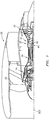
- FIG. 1 shows an exemplary turbomachine as a turbine engine, namely a turbofan engine 20.
- the exemplary engine 20 has a centerline or central longitudinal axis 500. From forward to aft and upstream to downstream, the engine comprises various sections including a fan 22, a low pressure compressor (LPC) 24, a high pressure compressor (HPC) 26, a combustor 28, a high pressure turbine (HPT) 30, and a low pressure turbine (LPT) 32.
- LPC low pressure compressor
- HPC high pressure compressor
- HPT high pressure turbine
- LPT low pressure turbine
- Each of the LPC, HPC, HPT, and LPT comprise multiple stages of blades interspersed with associated stages of vanes.
- the blade stages of the LPC are coupled to the blade stages of the LPT via a shaft 40 to be driven by the LPT.
- the blade stages of the HPC are coupled to the blade stages of the HPT via a shaft 42.
- the LPT and LPC blade stages and their associated shaft may form a low pressure spool.
- the HPC and HPT blade stages and their associated shaft may form a high pressure spool.
- the spools may be mounted for rotation about the centerline 500 via bearing systems (not shown). The rotating portions of the LPC, HPC, HPT, and LPT may form associated rotors.
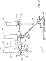
- FIG. 2 shows a portion of the LPC rotor 58 comprising three blade stages 60, 62, and 64 and an associated hub 66.
- Each exemplary blade stage is formed by an exemplary single piece disk.
- Each exemplary disk is formed out of an alloy (e.g., a titanium alloy or aluminum alloy) such as via machining.
- Each exemplary disk comprises an essentially full hoop rim structure 70 having an outboard/outer diameter (OD) surface/face 72 and an inboard/inner diameter (ID) surface/face 73.
- the disk further comprises a circumferential array of blade airfoils 74 extending from inboard ends at the rim 70 to outboard ends or tips 76.
- the exemplary airfoils each further extend from a leading edge 78 to a trailing edge 80 and have respective pressure sides and suction sides.
- the disk rim structure 70 itself has forward and aft rim surfaces or extremities 86 and 88.
- Each exemplary disk further includes an inboard/inner diameter (ID) annular protuberance or "bore” 90 having an inboard/inner diameter (ID) surface 92 defining a central aperture 94.
- the bore 90 is connected to the rim via an annular radial web 96 and provides structural integrity when the disk is under centrifugal load.
- the disk of the upstreammost first blade stage 60 further includes a rearwardly-extending sealing sleeve/spacer 100 which has a distal end bolted (via a bolt circle) to the web of the second stage disk.
- a pair of annular sealing edges 102 extend radially outward from the OD surface of the sleeve to engage seals of the intervening vane stage.
- a similar sleeve/spacer extends forward from the disk of the third blade stage.
- the exemplary hub 66 has an outboard flange similarly bolted to the second stage disk for transmitting torque from the LPT thereto.
- the rotor includes one or more places for mounting balance weights.
- a first location 120 is along the first stage rim; whereas, the second location 122 is along the third stage rim.
- the second location 122 features one of several conventional balancing systems.
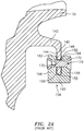
- the location 122 comprises a radially inwardly-directed flange 140 ( FIG. 2A ) extending inward from the distal end of a sleeve 142.
- the sleeve 142 extends aft and inward from an underside of the rim 70.
- the flange 140 may be partially scalloped or segmented to define individual tongues between the scallops. This segmentation reduces circumferential stress associated with balance weight mounting holes 150.
- the flange 140 has a forward surface/face 144 and an aft surface/face 146 between which the holes 150 extend.
- the inner diameter (ID) rim surface of the flange forms inboard ends 152 of the tongues.
- a conventional saddle weight 154 may be mounted at one or more of these holes 150.
- the exemplary saddle weight is generally U-shaped in longitudinal cross-section comprising a front wall 156 and an aft wall 158.
- An inboard wall 160 joins the front and aft walls and defines a channel therebetween which receives the flange.
- the front and aft walls have respective outboard ends 162 and 164.
- the inboard wall 160 has an upper surface 166 along the channel (forming a base of the channel) contacting the tongue inboard end 152.
- the front and aft walls have respective apertures 170 and 172 therethrough.
- An attachment rivet 176 extends through the apertures 170 and 172 and hole 150 to mount the weight to the flange.
- a computer spin balancing method may involve the computer controlling rotation of the rotor on a balancing machine and measuring vibratory forces. Based on the measured forces, the computer instructs the user to put one or more weights of given mass(s) at given tongue(s). The user does this and rivets the weight(s) to the tongue(s).
- one or more of the tongues of the flange may have weights mounted thereto and the weights may have different masses.
- Exemplary weight materials are metallic (e.g., stainless steel).
- One example involves twelve mass increments with the smallest weights having an average mass of 1.851 gram and the largest having an average mass of 4.434 grams. Thus an exemplary range of such increments provides a largest mass at least twice the smallest mass.
- the centrifugal loading of the weight is borne by the interaction between the tongue end 152 and channel base 166.
- the tongue end and channel base may be slightly spaced apart, contacting only under load. To facilitate this, there may be enough static play between the rivet shank and tongue hole.
- the securing of the weight to the tongue may alter the frequency response of the tongue.
- An unweighted tongue may have a given frequency response (e.g., one or more resonance frequencies).
- the existence of such resonance frequencies creates design/engineering considerations. For example, it is desirable to avoid having such resonance frequencies coincident with resonance frequencies of the airfoils of the blades of the associated disk so as to avoid adverse effects of coupling.
- FIG. 2B shows the forward balancing location 120 wherein a flange 200 is immediately along the underside 73 (inboard surface) of the rim of the first stage disk just forward of the web and immediately below the leading edge of the associated airfoils. This physical proximity of flange to airfoils greatly increases the potential significance of resonant behavior.
- the exemplary flange 200 has a circumferential array of scallops 204 ( FIG. 3 ) dividing the flange into interspersed circumferential arrays of first tongues 206 and second tongues 208.
- the exemplary first tongues 206 form weight mounting features/locations having associated mounting apertures/holes 210 extending between a forward surface 212 of the associated tongue and an aft surface 214 ( FIG. 2B ) thereof.
- Each of the holes has an exemplary axis 510.
- the exemplary holes 210 are defined by their perimeter surfaces 216.
- FIGS. 2B and 3 further show inboard ends 220 of the tongues (e.g., as annular cylindrical segments beveled at fore and aft junctions with the respective surfaces 212 and 214).
- FIG. 2B also shows an outboard root portion 222 of the flange and its tongues.
- FIG. 2B and 3 further show a saddle weight 154 at one such mounting location.
- An exemplary rotor has in excess of twenty such mounting locations. In a typical balancing situation, a small number of them will contain balance weights (e.g., 1-10).
- the exemplary balance weight 154 is a conventional saddle balance weight. However, additional modifications might be made.
- the exemplary attachment rivet 176 may be an otherwise conventional attachment rivet.
- Exemplary saddle weight bodies consist essentially of a metallic substrate (e.g., optionally coated). Exemplary substrate materials are metallic (e.g., stainless steel) and may be more dense than a density of the adjacent rotor material.
- exemplary attachment rivets are metallic (e.g., nickel alloy such as AMS 7232).
- the tongue 206 may be deliberately radially foreshortened or otherwise configured to provide a gap 230 by which the inboard end 220 is radially spaced apart from the channel base or inboard wall upper surface 166 in a normal range of operation.
- the exemplary balance location 120 has one or more abutment surfaces 232, 234 for engaging the outboard ends/rims 162, 164 of at least one of the front wall 156 and aft wall 158 of the balance weight 154.
- the exemplary abutment surfaces are formed as the inboard rims of radially inwardly extending flanges 236 (forward/fore) and 238 (aft/rear) projecting inward from the rim underside 73 (separated from the flange 200 by associated inwardly facing/open annular grooves/channels 240, 242, respectively).
- there are no grooves/channels 240, 242 so that the abutment surfaces are merely a longitudinally widened root portion of the flange 200.
- the exemplary hole 210 may be slightly oversized (e.g., defining an annular gap surrounding the shank of the rivet).
- the exemplary FIG. 2B neutral condition shows the shank (axis 512) and hole 210 (axis 510) to be coaxial.
- this may be departures from this either statically or under load.
- non-circular holes are also possible. This allows the rivet to avoid taking any centrifugal shear load.
- the exemplary weights have channel dimensions that are effective so that when installed with corresponding rivet tightness are in light frictional contact with the respective faces of the associated tongue. This light frictional contact may provide a damping and avoidance of rattling while not affecting the majority of radial load transmission.
- FIG. 3 also shows a conventional button weight 300 mounted at another of the mounting locations.
- the exemplary button weight 300 has a generally cylindrical head 302 and a shank 304.
- An exemplary button weight 300 consists essentially of a unitary metallic substrate (e.g., optionally coated) such as a nickel alloy (e.g., AMS 5665). This may be more dense than the density of the adjacent rotor material.
- the shank 304 extends through the associated hole 210 and has a perimeter/side surface 306 contacting the hole perimeter surface 206 to radially retain the button weight.
- the head has an underside 308 along the front surface 212.
- a deformed distal end portion 310 of the shank has an underside 312 clamping the weight against the aft surface 214.
- the exemplary hole and shank axes 510 and 514 are coincident.
- the exemplary head 302 has a lateral perimeter surface 320 (e.g., cylindrical).
- the exemplary forward abutment flange 236 has associated relieved areas (radial reliefs) 330 ( FIG. 3 ).
- a plurality of different masses of button weight are available sharing shank dimensions and head diameters but differing in mass and head length.
- the button weights have a range of masses lower than and not overlapping with the range of masses of the saddle weights.
- a smallest button weight has an average mass of 0.454 gram while a largest weight has a mass of 0.794 gram.
- an exemplary range of button weights has a largest mass at least 50% higher than a smallest.
- the FIG. 3 example shows a weight 300 of sufficient mass and head length so that, in the installed/mounted condition, the head 302 of the weight 300 is partially accommodated in the associated relieved area 330.
- the combination may be sufficiently close so that, under centrifugal load, the head contacts the surface of the relieved area to be radially supported thereby. This radial support would correspondingly reduce the torque applied by the button weight to the mounting flange and thereby reduce load on the mounting flange.
- the head may be short enough to be clear of the relieved area 330 when installed but may be accommodated by (pass through) the relieved area during insertion/installation.
- the exemplary shank 304 may have, along a majority of its length, sufficient radial clearance relative to the mounting hole so as to accommodate an anticipated range of differential thermal expansion (so as to avoid interference between the shank and the hole and thereby avoid associated stresses).
- the engagement may be borne by the deformed distal end portion whose thinned section may provide sufficient mechanical flexibility to accommodate differential thermal expansion with relatively small engagement forces.
- the relieved areas 330 may be formed via drilling/boring (e.g., at the same time as the drilling/boring of the holes 210 or before or after).
- the exemplary boring is of sufficient diameter to provide a slight radial gap 332 between the head 302 and the abutment flange 236. This also leaves the abutment surface engaging any weight 154 as two distinct circumferentially spaced surface portions on either circumferential side of the recess 330.
- the gross features are machined (e.g., turned) out of a titanium alloy billet. In one or more stages, this may machine all the rotationally symmetric features.
- the perimeter of the billet may then be machined to define the individual airfoils.
- the holes 210 and recesses 330 may, in turn, be machined. In one example, machining may otherwise be the same as conventionally used to machine a rotor with a turning step forming the ID at the flange 200. A subsequent turning step may define the ID of the flanges 236 and 238 and the channels separating them from the flange 200.
- the various rivet holes may be machined (e.g., using a back tapered end mill).
- the recesses 330 may than be machined.
- the recesses 204 may also be machined. The edges of the rivet holes and other features may then be broken.
- An exemplary balancing procedure involves: assemble the rotor stack together and place it in the balance machine (not shown); 2. spin to a balancing speed (e.g., 900 rpm); 3. measure (and record) balance (e.g., angle and amount of unbalance); 4. optionally repeat the spinning/measuring/recording one or more times for an average; apply weight(s) to correct measured (or avg.
- a balancing speed e.g., 900 rpm
- measure (and record) balance e.g., angle and amount of unbalance
- measured imbalance e.g., based upon computer or manual look-up table or computed best weight combination for a given imbalance
- re-spin and re-measure balance if balance not within target apply further weights to correct (may be done after additional re-spins/re-measurings to provide an average and may include replacing a given weight if more or less mass is indicated for a given weight position); once balance is within target, discontinue and remove from machine.
- this may involve merely modifying an existing manufacturing process via including the forming of the abutment flanges 236, 238 in the same step or sequence of steps as the main flange 200 and adding the formation of the recess 330.
Landscapes
- Engineering & Computer Science (AREA)
- General Engineering & Computer Science (AREA)
- Mechanical Engineering (AREA)
- Physics & Mathematics (AREA)
- Acoustics & Sound (AREA)
- Aviation & Aerospace Engineering (AREA)
- Turbine Rotor Nozzle Sealing (AREA)
Claims (15)
- Système d'équilibrage de rotor de turbomachine comprenant :
un réseau circonférentiel d'éléments de montage (206), chaque élément de montage comportant :une face avant (212) ;une face arrière (214) ;une extrémité intérieure (220) ; etun trou de montage (210) entre la face avant et la face arrière ;un ou plusieurs poids d'équilibrage (154), chaque poids d'équilibrage étant monté sur un élément de montage associé respectif (206) et comprenant :une paroi avant (156) le long de la face avant de l'élément de montage et comportant un trou (170) ;une paroi arrière (158) le long de la face arrière de l'élément de montage et comportant un trou (172) ; etune paroi radialement intérieure (160) à l'intérieur de l'extrémité intérieure de l'élément de montage ;une ou plusieurs attaches (176), chacune desdites attaches s'étendant au moins partiellement à travers les trous (170, 172) de la paroi avant (156) et de la paroi arrière (158) d'un desdits poids d'équilibrage associé (154) et à travers le trou (210) de l'élément de montage associé (206) ; etune surface de butée (232, 234) du rotor positionnée pour venir en prise avec une extrémité extérieure (162, 164) de l'une au moins de la paroi avant (156) et de la paroi arrière (158) de chacun desdits poids d'équilibrage (154). - Système selon la revendication 1, dans lequel le réseau circonférentiel d'éléments de montage comprend un réseau circonférentiel d'emplacements le long d'une bride unique (200) .
- Système selon la revendication 1 ou 2, dans lequel le réseau circonférentiel d'éléments de montage comprend un réseau circonférentiel de languettes faisant saillie radialement vers l'intérieur.
- Système selon la revendication 1, 2 ou 3, dans lequel il y a une surface avant de ladite surface de butée (232) venant en prise avec la paroi avant (156) et une surface arrière de ladite surface de butée (234) venant en prise avec la paroi arrière (158).
- Système selon une quelconque revendication précédente, dans lequel chacune desdites attaches (176) est un rivet.
- Système selon une quelconque revendication précédente, dans lequel il y a une pluralité desdits poids d'équilibrage (154) .
- Système selon une quelconque revendication précédente, dans lequel la surface de butée (232, 234) comprend une extrémité interne d'une bride de butée faisant saillie radialement vers l'intérieur (236, 238).
- Système selon la revendication 7, dans lequel il y a une pluralité de zones dégagées (330) dans la bride de butée (236, 238), chaque zone dégagée (330) étant alignée radialement avec le trou de montage (210) d'un dudit élément de montage associé.
- Système selon la revendication 8, dans lequel une ou plusieurs desdites zones dégagées (330) reçoivent une tête (302) d'un poids de bouton associé (300), le poids de bouton comportant une tige (304) s'étendant à travers le trou de montage associé (210).
- Système selon la revendication 7 ou 8, comprenant en outre au moins un contre-rivet à tête bouton (300) s'étendant à travers le trou d'un desdits éléments de montage associés et comportant une tête (302) logée dans un évidement radial (330) dans la bride de butée (236, 238).
- Système selon une quelconque revendication précédente, dans lequel la paroi intérieure du poids d'équilibrage (154) est espacée de l'extrémité intérieure de l'élément de montage par un intervalle (230).
- Système selon la revendication 1, dans lequel la surface de butée (232, 234) est positionnée pour venir en prise avec l'extrémité extérieure afin de résister au mouvement radial extérieur du poids (154).
- Système selon une quelconque revendication précédente, dans lequel le rotor (58) est un rotor de moteur à turbine à gaz, de préférence le rotor (58) est un rotor de compresseur d'un moteur à turbine à gaz et, de manière davantage préférée, le rotor (58) est un rotor de compresseur basse pression d'un moteur à turbine à gaz.
- Procédé d'utilisation du système selon une quelconque revendication précédente, le procédé comprenant :la rotation du rotor (58) autour d'un axe ;la mesure des paramètres de vibration du rotor en rotation ;l'installation desdits un ou plusieurs poids d'équilibrage (154) pour améliorer l'équilibre du rotor (58) ; etla rotation du rotor (58) pour provoquer la mise en prise des poids d'équilibrage installés (154) sur la surface de butée (232, 234).
- Rotor de turbomachine (58) comprenant :
un réseau circonférentiel d'éléments de montage de poids d'équilibrage (206), chaque élément de montage (206) comportant :une face avant (212) ;une face arrière (214) ;une extrémité intérieure (220) ; etun trou de montage (210) entre la face avant et la face arrière ;une bride de butée avant (236) faisant saillie radialement vers l'intérieur, espacée immédiatement devant le réseau circonférentiel d'éléments de montage (206) ; etune bride de butée arrière (238) faisant saillie radialement vers l'intérieur, espacée immédiatement derrière le réseau circonférentiel d'éléments de montage (206).
Applications Claiming Priority (2)
| Application Number | Priority Date | Filing Date | Title |
|---|---|---|---|
| US13/417,454 US8888458B2 (en) | 2012-03-12 | 2012-03-12 | Turbomachine rotor balancing system |
| PCT/US2013/026631 WO2013138023A1 (fr) | 2012-03-12 | 2013-02-19 | Système d'équilibrage de rotor de turbomachine |
Publications (3)
| Publication Number | Publication Date |
|---|---|
| EP2825746A1 EP2825746A1 (fr) | 2015-01-21 |
| EP2825746A4 EP2825746A4 (fr) | 2015-10-28 |
| EP2825746B1 true EP2825746B1 (fr) | 2019-10-02 |
Family
ID=49114274
Family Applications (1)
| Application Number | Title | Priority Date | Filing Date |
|---|---|---|---|
| EP13761712.2A Active EP2825746B1 (fr) | 2012-03-12 | 2013-02-19 | Système d'équilibrage de rotor de turbomachine, rotor de turbomachine et procédé d'utilisation de ce système |
Country Status (4)
| Country | Link |
|---|---|
| US (1) | US8888458B2 (fr) |
| EP (1) | EP2825746B1 (fr) |
| SG (1) | SG11201404464YA (fr) |
| WO (1) | WO2013138023A1 (fr) |
Families Citing this family (33)
| Publication number | Priority date | Publication date | Assignee | Title |
|---|---|---|---|---|
| US9410427B2 (en) * | 2012-06-05 | 2016-08-09 | United Technologies Corporation | Compressor power and torque transmitting hub |
| US9388697B2 (en) * | 2012-07-17 | 2016-07-12 | Solar Turbines Incorporated | First stage compressor disk configured for balancing the compressor rotor assembly |
| FR3001515B1 (fr) * | 2013-01-25 | 2015-03-20 | Snecma | Assemblage de masselotte d'equilibrage a un element de rotor |
| US9567857B2 (en) * | 2013-03-08 | 2017-02-14 | Rolls-Royce North American Technologies, Inc. | Turbine split ring retention and anti-rotation method |
| EP3058175B1 (fr) * | 2013-09-26 | 2019-06-19 | United Technologies Corporation | Composant rotatif équilibré pour une turbine à gaz |
| FR3011575B1 (fr) * | 2013-10-09 | 2018-02-16 | Safran Aircraft Engines | Disque pour l'equilibrage d'un rotor, et rotor |
| FR3021066B1 (fr) * | 2014-05-19 | 2019-05-10 | Safran Aircraft Engines | Disque de rotor equilibre, et procede d'equilibrage |
| FR3021065B1 (fr) * | 2014-05-19 | 2016-11-25 | Snecma | Module equilibre comprenant un disque de rotor, et procede d'equilibrage |
| EP3091177B1 (fr) * | 2015-05-07 | 2017-12-20 | MTU Aero Engines GmbH | Rotor pour une turbomachine et compresseur |
| US10024165B2 (en) * | 2015-11-20 | 2018-07-17 | United Technologies Corporation | De-oiler balance weights for turbomachine rotors and systems for removing excess oil from turbomachine rotors |
| US10323519B2 (en) * | 2016-06-23 | 2019-06-18 | United Technologies Corporation | Gas turbine engine having a turbine rotor with torque transfer and balance features |
| DE102017207283A1 (de) * | 2017-04-28 | 2018-10-31 | Rolls-Royce Deutschland Ltd & Co Kg | Rotoranordnung mit Wuchtelement und Verfahren zur Montage eines Wuchtelements |
| US20180320522A1 (en) * | 2017-05-04 | 2018-11-08 | Rolls-Royce Corporation | Turbine assembly with auxiliary wheel |
| US10774678B2 (en) | 2017-05-04 | 2020-09-15 | Rolls-Royce Corporation | Turbine assembly with auxiliary wheel |
| US10968744B2 (en) | 2017-05-04 | 2021-04-06 | Rolls-Royce Corporation | Turbine rotor assembly having a retaining collar for a bayonet mount |
| US10865646B2 (en) | 2017-05-04 | 2020-12-15 | Rolls-Royce Corporation | Turbine assembly with auxiliary wheel |
| DE102017109952A1 (de) * | 2017-05-09 | 2018-11-15 | Rolls-Royce Deutschland Ltd & Co Kg | Rotorvorrichtung einer Strömungsmaschine |
| US10697300B2 (en) | 2017-12-14 | 2020-06-30 | Raytheon Technologies Corporation | Rotor balance weight system |
| WO2019182832A1 (fr) * | 2018-03-23 | 2019-09-26 | Dana Automotive Systems Group, Llc | Correction d'un déséquilibre dans un arbre rotatif |
| FR3081495B1 (fr) * | 2018-05-24 | 2020-05-29 | Safran Aircraft Engines | Dispositif d'equilibrage pour un rotor de turbomachine d'aeronef et rotor le comprenant |
| US10907477B2 (en) * | 2018-06-18 | 2021-02-02 | Raytheon Technologies Corporation | Clip and pin balance for rotor |
| FR3091721B1 (fr) * | 2019-01-10 | 2021-01-15 | Safran Aircraft Engines | Rotor de turbomachine a masselotte |
| US10954861B2 (en) * | 2019-03-14 | 2021-03-23 | Raytheon Technologies Corporation | Seal for a gas turbine engine |
| US11448081B2 (en) | 2019-10-18 | 2022-09-20 | Raytheon Technologies Corporation | Balanced circumferential seal |
| US11480071B2 (en) * | 2020-06-02 | 2022-10-25 | Pratt & Whitney Canada Corp. | Balancing ring geometry |
| US11578599B2 (en) * | 2021-02-02 | 2023-02-14 | Pratt & Whitney Canada Corp. | Rotor balance assembly |
| FR3119647B1 (fr) | 2021-02-11 | 2023-01-13 | Safran Aircraft Engines | Procédé de réparation d’une bride de rotor de turbomachine |
| US11976564B1 (en) | 2023-03-30 | 2024-05-07 | Rolls-Royce North American Technologies Inc. | Splined balance weight for rotating components in gas turbine engines |
| US12228052B2 (en) * | 2023-07-19 | 2025-02-18 | Pratt & Whitney Canada Corp. | Integrally bladed rotor with increased rim bending stiffness |
| US12018579B1 (en) | 2023-08-08 | 2024-06-25 | Rolls-Royce North American Technologies Inc. | Clocking balance weight rotor assembly for gas turbine engines |
| US12018580B1 (en) | 2023-08-08 | 2024-06-25 | Rolls-Royce North American Technologies Inc. | Rotor assembly for gas turbine engines with replaceable balance weight pins |
| US12305528B2 (en) | 2023-08-08 | 2025-05-20 | Rolls-Royce North American Technologies Inc. | Rotor assembly for gas turbine engines with replaceable balance weight bands |
| US12352177B2 (en) | 2023-11-29 | 2025-07-08 | Pratt & Whitney Canada Corp. | Unbalanced rotor for unbalance testing of aircraft power plant |
Family Cites Families (16)
| Publication number | Priority date | Publication date | Assignee | Title |
|---|---|---|---|---|
| FR2404212A1 (fr) | 1977-09-23 | 1979-04-20 | Snecma | Dispositif d'equilibrage d'un rotor |
| US4485678A (en) | 1982-09-27 | 1984-12-04 | Mechanical Technology Incorporated | Rotor diagnostic and balancing system |
| US4879792A (en) | 1988-11-07 | 1989-11-14 | Unitedtechnologies Corporation | Method of balancing rotors |
| US5412583A (en) | 1993-06-10 | 1995-05-02 | Dynamics Research Corp. | Computer implemented balancer |
| US5724271A (en) | 1994-03-25 | 1998-03-03 | General Electric Company | Model-based method for optimized field balancing of rotating machinery |
| US6893222B2 (en) | 2003-02-10 | 2005-05-17 | United Technologies Corporation | Turbine balancing |
| FR2868807B1 (fr) | 2004-04-09 | 2008-12-05 | Snecma Moteurs Sa | Dispositif d'equilibrage d'une piece en rotation en particulier d'un rotor de turboreacteur |
| US7371042B2 (en) | 2004-12-21 | 2008-05-13 | General Electric Company | Method and apparatus for balancing gas turbine engines |
| FR2885196B1 (fr) | 2005-04-29 | 2007-06-29 | Snecma Moteurs Sa | Dispositif d'equilibrage d'un rotor de turbomachine |
| FR2907498B1 (fr) | 2006-10-24 | 2009-01-23 | Snecma Sa | Systeme d'equilibrage pour rotor de turbomachine |
| FR2907497B1 (fr) | 2006-10-24 | 2009-01-23 | Snecma Sa | Systeme d'equilibrage pour rotor de turbomachine |
| US7685876B2 (en) | 2006-12-20 | 2010-03-30 | General Electric Company | Methods and systems for balancing a rotatable member |
| DE102008016329A1 (de) * | 2008-03-28 | 2009-10-01 | Rolls-Royce Deutschland Ltd & Co Kg | Anordnung zum Auswuchten eines Rotors |
| US8353670B2 (en) | 2009-07-30 | 2013-01-15 | Pratt & Whitney Canada Corp. | Axial balancing clip weight for rotor assembly and method for balancing a rotor assembly |
| US8506253B2 (en) * | 2009-08-19 | 2013-08-13 | Pratt & Whitney Canada Corp. | Balancing apparatus for rotor assembly |
| US8631578B2 (en) | 2009-10-01 | 2014-01-21 | Pratt & Whitney Canada Corp. | Radial balancing clip weight for rotor assembly |
-
2012
- 2012-03-12 US US13/417,454 patent/US8888458B2/en active Active
-
2013
- 2013-02-19 EP EP13761712.2A patent/EP2825746B1/fr active Active
- 2013-02-19 WO PCT/US2013/026631 patent/WO2013138023A1/fr not_active Ceased
- 2013-02-19 SG SG11201404464YA patent/SG11201404464YA/en unknown
Non-Patent Citations (1)
| Title |
|---|
| None * |
Also Published As
| Publication number | Publication date |
|---|---|
| EP2825746A1 (fr) | 2015-01-21 |
| US20130236310A1 (en) | 2013-09-12 |
| WO2013138023A1 (fr) | 2013-09-19 |
| SG11201404464YA (en) | 2014-10-30 |
| EP2825746A4 (fr) | 2015-10-28 |
| US8888458B2 (en) | 2014-11-18 |
Similar Documents
| Publication | Publication Date | Title |
|---|---|---|
| US8888458B2 (en) | Turbomachine rotor balancing system | |
| EP3093435B1 (fr) | Amortisseur de rotor | |
| EP3809022B1 (fr) | Joint d'étanchéité circonférentiel équilibré | |
| EP2169181B1 (fr) | Rotor de turbine à gaz et masse d'équilibrage associée | |
| US8092183B2 (en) | Fan rotor for a turbomachine or a test engine | |
| EP2540980B1 (fr) | Ammortisseur pour rotor aubagé intégral | |
| US6354780B1 (en) | Eccentric balanced blisk | |
| EP2264280B1 (fr) | Correction de balourd de turbines | |
| US10570741B2 (en) | Method of balancing a gas turbine engine rotor | |
| EP3026212B1 (fr) | Dégagement de face de grille monobloc | |
| US10436224B2 (en) | Method and apparatus for balancing a rotor | |
| EP3054088B1 (fr) | Équilibrage de disque de rotor de moteur à turbine à gaz | |
| EP3318737B1 (fr) | Ensemble de cône d'entrée de faible poids | |
| EP3318738B1 (fr) | Ensemble de cône d'entrée sans élément de fixation | |
| EP4036428B1 (fr) | Asymétrie dans un ressort de centrage annulaire | |
| EP1111193A2 (fr) | Système de verrouillage axial des aubes de turbomachines | |
| US10024165B2 (en) | De-oiler balance weights for turbomachine rotors and systems for removing excess oil from turbomachine rotors | |
| US20080050226A1 (en) | Methods and apparatus for fabricating a rotor for a steam turbine | |
| EP4667710A1 (fr) | Support de palier frangible à rayons de flambage |
Legal Events
| Date | Code | Title | Description |
|---|---|---|---|
| PUAI | Public reference made under article 153(3) epc to a published international application that has entered the european phase |
Free format text: ORIGINAL CODE: 0009012 |
|
| 17P | Request for examination filed |
Effective date: 20131223 |
|
| AK | Designated contracting states |
Kind code of ref document: A1 Designated state(s): AL AT BE BG CH CY CZ DE DK EE ES FI FR GB GR HR HU IE IS IT LI LT LU LV MC MK MT NL NO PL PT RO RS SE SI SK SM TR |
|
| AX | Request for extension of the european patent |
Extension state: BA ME |
|
| RIN1 | Information on inventor provided before grant (corrected) |
Inventor name: BILLINGS, SCOTT, C. Inventor name: WU, ZHEN Inventor name: GIANNAKOPOULOS, KONSTANTINOS, P. |
|
| RIN1 | Information on inventor provided before grant (corrected) |
Inventor name: BILLINGS, SCOTT, C. Inventor name: WU, ZHEN Inventor name: GIANNAKOPOULOS, KONSTANTINOS, P. |
|
| DAX | Request for extension of the european patent (deleted) | ||
| RA4 | Supplementary search report drawn up and despatched (corrected) |
Effective date: 20150930 |
|
| RIC1 | Information provided on ipc code assigned before grant |
Ipc: F04D 29/66 20060101ALI20150924BHEP Ipc: F16F 15/34 20060101ALI20150924BHEP Ipc: G01M 1/30 20060101ALI20150924BHEP Ipc: F01D 5/02 20060101AFI20150924BHEP Ipc: F01D 25/04 20060101ALI20150924BHEP |
|
| RAP1 | Party data changed (applicant data changed or rights of an application transferred) |
Owner name: UNITED TECHNOLOGIES CORPORATION |
|
| REG | Reference to a national code |
Ref country code: DE Ref legal event code: R079 Ref document number: 602013061241 Country of ref document: DE Free format text: PREVIOUS MAIN CLASS: F02C0007000000 Ipc: F01D0005020000 |
|
| GRAP | Despatch of communication of intention to grant a patent |
Free format text: ORIGINAL CODE: EPIDOSNIGR1 |
|
| STAA | Information on the status of an ep patent application or granted ep patent |
Free format text: STATUS: GRANT OF PATENT IS INTENDED |
|
| RIC1 | Information provided on ipc code assigned before grant |
Ipc: F04D 29/66 20060101ALI20190305BHEP Ipc: G01M 1/30 20060101ALI20190305BHEP Ipc: F16F 15/34 20060101ALI20190305BHEP Ipc: F01D 25/04 20060101ALI20190305BHEP Ipc: F01D 5/02 20060101AFI20190305BHEP |
|
| INTG | Intention to grant announced |
Effective date: 20190409 |
|
| GRAS | Grant fee paid |
Free format text: ORIGINAL CODE: EPIDOSNIGR3 |
|
| GRAA | (expected) grant |
Free format text: ORIGINAL CODE: 0009210 |
|
| STAA | Information on the status of an ep patent application or granted ep patent |
Free format text: STATUS: THE PATENT HAS BEEN GRANTED |
|
| AK | Designated contracting states |
Kind code of ref document: B1 Designated state(s): AL AT BE BG CH CY CZ DE DK EE ES FI FR GB GR HR HU IE IS IT LI LT LU LV MC MK MT NL NO PL PT RO RS SE SI SK SM TR |
|
| REG | Reference to a national code |
Ref country code: GB Ref legal event code: FG4D |
|
| REG | Reference to a national code |
Ref country code: CH Ref legal event code: EP Ref country code: AT Ref legal event code: REF Ref document number: 1186372 Country of ref document: AT Kind code of ref document: T Effective date: 20191015 |
|
| REG | Reference to a national code |
Ref country code: DE Ref legal event code: R096 Ref document number: 602013061241 Country of ref document: DE |
|
| REG | Reference to a national code |
Ref country code: IE Ref legal event code: FG4D |
|
| REG | Reference to a national code |
Ref country code: NL Ref legal event code: MP Effective date: 20191002 |
|
| REG | Reference to a national code |
Ref country code: LT Ref legal event code: MG4D |
|
| REG | Reference to a national code |
Ref country code: AT Ref legal event code: MK05 Ref document number: 1186372 Country of ref document: AT Kind code of ref document: T Effective date: 20191002 |
|
| PG25 | Lapsed in a contracting state [announced via postgrant information from national office to epo] |
Ref country code: PT Free format text: LAPSE BECAUSE OF FAILURE TO SUBMIT A TRANSLATION OF THE DESCRIPTION OR TO PAY THE FEE WITHIN THE PRESCRIBED TIME-LIMIT Effective date: 20200203 Ref country code: FI Free format text: LAPSE BECAUSE OF FAILURE TO SUBMIT A TRANSLATION OF THE DESCRIPTION OR TO PAY THE FEE WITHIN THE PRESCRIBED TIME-LIMIT Effective date: 20191002 Ref country code: BG Free format text: LAPSE BECAUSE OF FAILURE TO SUBMIT A TRANSLATION OF THE DESCRIPTION OR TO PAY THE FEE WITHIN THE PRESCRIBED TIME-LIMIT Effective date: 20200102 Ref country code: GR Free format text: LAPSE BECAUSE OF FAILURE TO SUBMIT A TRANSLATION OF THE DESCRIPTION OR TO PAY THE FEE WITHIN THE PRESCRIBED TIME-LIMIT Effective date: 20200103 Ref country code: LV Free format text: LAPSE BECAUSE OF FAILURE TO SUBMIT A TRANSLATION OF THE DESCRIPTION OR TO PAY THE FEE WITHIN THE PRESCRIBED TIME-LIMIT Effective date: 20191002 Ref country code: SE Free format text: LAPSE BECAUSE OF FAILURE TO SUBMIT A TRANSLATION OF THE DESCRIPTION OR TO PAY THE FEE WITHIN THE PRESCRIBED TIME-LIMIT Effective date: 20191002 Ref country code: NO Free format text: LAPSE BECAUSE OF FAILURE TO SUBMIT A TRANSLATION OF THE DESCRIPTION OR TO PAY THE FEE WITHIN THE PRESCRIBED TIME-LIMIT Effective date: 20200102 Ref country code: AT Free format text: LAPSE BECAUSE OF FAILURE TO SUBMIT A TRANSLATION OF THE DESCRIPTION OR TO PAY THE FEE WITHIN THE PRESCRIBED TIME-LIMIT Effective date: 20191002 Ref country code: NL Free format text: LAPSE BECAUSE OF FAILURE TO SUBMIT A TRANSLATION OF THE DESCRIPTION OR TO PAY THE FEE WITHIN THE PRESCRIBED TIME-LIMIT Effective date: 20191002 Ref country code: PL Free format text: LAPSE BECAUSE OF FAILURE TO SUBMIT A TRANSLATION OF THE DESCRIPTION OR TO PAY THE FEE WITHIN THE PRESCRIBED TIME-LIMIT Effective date: 20191002 Ref country code: LT Free format text: LAPSE BECAUSE OF FAILURE TO SUBMIT A TRANSLATION OF THE DESCRIPTION OR TO PAY THE FEE WITHIN THE PRESCRIBED TIME-LIMIT Effective date: 20191002 Ref country code: ES Free format text: LAPSE BECAUSE OF FAILURE TO SUBMIT A TRANSLATION OF THE DESCRIPTION OR TO PAY THE FEE WITHIN THE PRESCRIBED TIME-LIMIT Effective date: 20191002 |
|
| PG25 | Lapsed in a contracting state [announced via postgrant information from national office to epo] |
Ref country code: IS Free format text: LAPSE BECAUSE OF FAILURE TO SUBMIT A TRANSLATION OF THE DESCRIPTION OR TO PAY THE FEE WITHIN THE PRESCRIBED TIME-LIMIT Effective date: 20200224 Ref country code: CZ Free format text: LAPSE BECAUSE OF FAILURE TO SUBMIT A TRANSLATION OF THE DESCRIPTION OR TO PAY THE FEE WITHIN THE PRESCRIBED TIME-LIMIT Effective date: 20191002 Ref country code: RS Free format text: LAPSE BECAUSE OF FAILURE TO SUBMIT A TRANSLATION OF THE DESCRIPTION OR TO PAY THE FEE WITHIN THE PRESCRIBED TIME-LIMIT Effective date: 20191002 Ref country code: HR Free format text: LAPSE BECAUSE OF FAILURE TO SUBMIT A TRANSLATION OF THE DESCRIPTION OR TO PAY THE FEE WITHIN THE PRESCRIBED TIME-LIMIT Effective date: 20191002 |
|
| PG25 | Lapsed in a contracting state [announced via postgrant information from national office to epo] |
Ref country code: AL Free format text: LAPSE BECAUSE OF FAILURE TO SUBMIT A TRANSLATION OF THE DESCRIPTION OR TO PAY THE FEE WITHIN THE PRESCRIBED TIME-LIMIT Effective date: 20191002 |
|
| REG | Reference to a national code |
Ref country code: DE Ref legal event code: R097 Ref document number: 602013061241 Country of ref document: DE |
|
| PG2D | Information on lapse in contracting state deleted |
Ref country code: IS |
|
| PG25 | Lapsed in a contracting state [announced via postgrant information from national office to epo] |
Ref country code: EE Free format text: LAPSE BECAUSE OF FAILURE TO SUBMIT A TRANSLATION OF THE DESCRIPTION OR TO PAY THE FEE WITHIN THE PRESCRIBED TIME-LIMIT Effective date: 20191002 Ref country code: DK Free format text: LAPSE BECAUSE OF FAILURE TO SUBMIT A TRANSLATION OF THE DESCRIPTION OR TO PAY THE FEE WITHIN THE PRESCRIBED TIME-LIMIT Effective date: 20191002 Ref country code: RO Free format text: LAPSE BECAUSE OF FAILURE TO SUBMIT A TRANSLATION OF THE DESCRIPTION OR TO PAY THE FEE WITHIN THE PRESCRIBED TIME-LIMIT Effective date: 20191002 Ref country code: IS Free format text: LAPSE BECAUSE OF FAILURE TO SUBMIT A TRANSLATION OF THE DESCRIPTION OR TO PAY THE FEE WITHIN THE PRESCRIBED TIME-LIMIT Effective date: 20200202 |
|
| PLBE | No opposition filed within time limit |
Free format text: ORIGINAL CODE: 0009261 |
|
| STAA | Information on the status of an ep patent application or granted ep patent |
Free format text: STATUS: NO OPPOSITION FILED WITHIN TIME LIMIT |
|
| PG25 | Lapsed in a contracting state [announced via postgrant information from national office to epo] |
Ref country code: IT Free format text: LAPSE BECAUSE OF FAILURE TO SUBMIT A TRANSLATION OF THE DESCRIPTION OR TO PAY THE FEE WITHIN THE PRESCRIBED TIME-LIMIT Effective date: 20191002 Ref country code: SM Free format text: LAPSE BECAUSE OF FAILURE TO SUBMIT A TRANSLATION OF THE DESCRIPTION OR TO PAY THE FEE WITHIN THE PRESCRIBED TIME-LIMIT Effective date: 20191002 Ref country code: SK Free format text: LAPSE BECAUSE OF FAILURE TO SUBMIT A TRANSLATION OF THE DESCRIPTION OR TO PAY THE FEE WITHIN THE PRESCRIBED TIME-LIMIT Effective date: 20191002 |
|
| 26N | No opposition filed |
Effective date: 20200703 |
|
| REG | Reference to a national code |
Ref country code: CH Ref legal event code: PL |
|
| REG | Reference to a national code |
Ref country code: BE Ref legal event code: MM Effective date: 20200229 |
|
| PG25 | Lapsed in a contracting state [announced via postgrant information from national office to epo] |
Ref country code: MC Free format text: LAPSE BECAUSE OF FAILURE TO SUBMIT A TRANSLATION OF THE DESCRIPTION OR TO PAY THE FEE WITHIN THE PRESCRIBED TIME-LIMIT Effective date: 20191002 Ref country code: LU Free format text: LAPSE BECAUSE OF NON-PAYMENT OF DUE FEES Effective date: 20200219 |
|
| PG25 | Lapsed in a contracting state [announced via postgrant information from national office to epo] |
Ref country code: CH Free format text: LAPSE BECAUSE OF NON-PAYMENT OF DUE FEES Effective date: 20200229 Ref country code: LI Free format text: LAPSE BECAUSE OF NON-PAYMENT OF DUE FEES Effective date: 20200229 Ref country code: SI Free format text: LAPSE BECAUSE OF FAILURE TO SUBMIT A TRANSLATION OF THE DESCRIPTION OR TO PAY THE FEE WITHIN THE PRESCRIBED TIME-LIMIT Effective date: 20191002 |
|
| PG25 | Lapsed in a contracting state [announced via postgrant information from national office to epo] |
Ref country code: IE Free format text: LAPSE BECAUSE OF NON-PAYMENT OF DUE FEES Effective date: 20200219 |
|
| PG25 | Lapsed in a contracting state [announced via postgrant information from national office to epo] |
Ref country code: BE Free format text: LAPSE BECAUSE OF NON-PAYMENT OF DUE FEES Effective date: 20200229 |
|
| PG25 | Lapsed in a contracting state [announced via postgrant information from national office to epo] |
Ref country code: TR Free format text: LAPSE BECAUSE OF FAILURE TO SUBMIT A TRANSLATION OF THE DESCRIPTION OR TO PAY THE FEE WITHIN THE PRESCRIBED TIME-LIMIT Effective date: 20191002 Ref country code: MT Free format text: LAPSE BECAUSE OF FAILURE TO SUBMIT A TRANSLATION OF THE DESCRIPTION OR TO PAY THE FEE WITHIN THE PRESCRIBED TIME-LIMIT Effective date: 20191002 Ref country code: CY Free format text: LAPSE BECAUSE OF FAILURE TO SUBMIT A TRANSLATION OF THE DESCRIPTION OR TO PAY THE FEE WITHIN THE PRESCRIBED TIME-LIMIT Effective date: 20191002 |
|
| PG25 | Lapsed in a contracting state [announced via postgrant information from national office to epo] |
Ref country code: MK Free format text: LAPSE BECAUSE OF FAILURE TO SUBMIT A TRANSLATION OF THE DESCRIPTION OR TO PAY THE FEE WITHIN THE PRESCRIBED TIME-LIMIT Effective date: 20191002 |
|
| REG | Reference to a national code |
Ref country code: DE Ref legal event code: R081 Ref document number: 602013061241 Country of ref document: DE Owner name: RAYTHEON TECHNOLOGIES CORPORATION (N.D.GES.D.S, US Free format text: FORMER OWNER: UNITED TECHNOLOGIES CORPORATION, FARMINGTON, CONN., US Ref country code: DE Ref legal event code: R081 Ref document number: 602013061241 Country of ref document: DE Owner name: RTX CORPORATION (N.D.GES.D. STAATES DELAWARE),, US Free format text: FORMER OWNER: UNITED TECHNOLOGIES CORPORATION, FARMINGTON, CONN., US |
|
| P01 | Opt-out of the competence of the unified patent court (upc) registered |
Effective date: 20230520 |
|
| REG | Reference to a national code |
Ref country code: DE Ref legal event code: R081 Ref document number: 602013061241 Country of ref document: DE Owner name: RTX CORPORATION (N.D.GES.D. STAATES DELAWARE),, US Free format text: FORMER OWNER: RAYTHEON TECHNOLOGIES CORPORATION (N.D.GES.D.STAATES DELAWARE), ARLINGTON, VA, US |
|
| PGFP | Annual fee paid to national office [announced via postgrant information from national office to epo] |
Ref country code: GB Payment date: 20260121 Year of fee payment: 14 |
|
| PGFP | Annual fee paid to national office [announced via postgrant information from national office to epo] |
Ref country code: DE Payment date: 20260121 Year of fee payment: 14 |
|
| PGFP | Annual fee paid to national office [announced via postgrant information from national office to epo] |
Ref country code: FR Payment date: 20260121 Year of fee payment: 14 |