EP2825923B1 - Verfahren zum ermitteln und optimieren eines energieverbrauchs eines produktionssystems - Google Patents
Verfahren zum ermitteln und optimieren eines energieverbrauchs eines produktionssystems Download PDFInfo
- Publication number
- EP2825923B1 EP2825923B1 EP12722125.7A EP12722125A EP2825923B1 EP 2825923 B1 EP2825923 B1 EP 2825923B1 EP 12722125 A EP12722125 A EP 12722125A EP 2825923 B1 EP2825923 B1 EP 2825923B1
- Authority
- EP
- European Patent Office
- Prior art keywords
- production system
- energy
- load
- determined
- energy consumption
- Prior art date
- Legal status (The legal status is an assumption and is not a legal conclusion. Google has not performed a legal analysis and makes no representation as to the accuracy of the status listed.)
- Not-in-force
Links
Images

Classifications
-
- G—PHYSICS
- G01—MEASURING; TESTING
- G01R—MEASURING ELECTRIC VARIABLES; MEASURING MAGNETIC VARIABLES
- G01R21/00—Arrangements for measuring electric power or power factor
- G01R21/133—Arrangements for measuring electric power or power factor by using digital technique
-
- G—PHYSICS
- G05—CONTROLLING; REGULATING
- G05B—CONTROL OR REGULATING SYSTEMS IN GENERAL; FUNCTIONAL ELEMENTS OF SUCH SYSTEMS; MONITORING OR TESTING ARRANGEMENTS FOR SUCH SYSTEMS OR ELEMENTS
- G05B15/00—Systems controlled by a computer
- G05B15/02—Systems controlled by a computer electric
-
- G—PHYSICS
- G05—CONTROLLING; REGULATING
- G05B—CONTROL OR REGULATING SYSTEMS IN GENERAL; FUNCTIONAL ELEMENTS OF SUCH SYSTEMS; MONITORING OR TESTING ARRANGEMENTS FOR SUCH SYSTEMS OR ELEMENTS
- G05B13/00—Adaptive control systems, i.e. systems automatically adjusting themselves to have a performance which is optimum according to some preassigned criterion
- G05B13/02—Adaptive control systems, i.e. systems automatically adjusting themselves to have a performance which is optimum according to some preassigned criterion electric
- G05B13/04—Adaptive control systems, i.e. systems automatically adjusting themselves to have a performance which is optimum according to some preassigned criterion electric involving the use of models or simulators
-
- G—PHYSICS
- G05—CONTROLLING; REGULATING
- G05B—CONTROL OR REGULATING SYSTEMS IN GENERAL; FUNCTIONAL ELEMENTS OF SUCH SYSTEMS; MONITORING OR TESTING ARRANGEMENTS FOR SUCH SYSTEMS OR ELEMENTS
- G05B17/00—Systems involving the use of models or simulators of said systems
- G05B17/02—Systems involving the use of models or simulators of said systems electric
-
- G—PHYSICS
- G06—COMPUTING OR CALCULATING; COUNTING
- G06Q—INFORMATION AND COMMUNICATION TECHNOLOGY [ICT] SPECIALLY ADAPTED FOR ADMINISTRATIVE, COMMERCIAL, FINANCIAL, MANAGERIAL OR SUPERVISORY PURPOSES; SYSTEMS OR METHODS SPECIALLY ADAPTED FOR ADMINISTRATIVE, COMMERCIAL, FINANCIAL, MANAGERIAL OR SUPERVISORY PURPOSES, NOT OTHERWISE PROVIDED FOR
- G06Q10/00—Administration; Management
- G06Q10/04—Forecasting or optimisation specially adapted for administrative or management purposes, e.g. linear programming or "cutting stock problem"
-
- G—PHYSICS
- G06—COMPUTING OR CALCULATING; COUNTING
- G06Q—INFORMATION AND COMMUNICATION TECHNOLOGY [ICT] SPECIALLY ADAPTED FOR ADMINISTRATIVE, COMMERCIAL, FINANCIAL, MANAGERIAL OR SUPERVISORY PURPOSES; SYSTEMS OR METHODS SPECIALLY ADAPTED FOR ADMINISTRATIVE, COMMERCIAL, FINANCIAL, MANAGERIAL OR SUPERVISORY PURPOSES, NOT OTHERWISE PROVIDED FOR
- G06Q10/00—Administration; Management
- G06Q10/06—Resources, workflows, human or project management; Enterprise or organisation planning; Enterprise or organisation modelling
Definitions
- the present invention relates to a method for determining an energy consumption of a production system. Moreover, the present invention relates to a method of operating a production system.
- Production systems are currently being simulated during a very early design phase to increase throughput and efficiency.
- simulation programs such as Plant Simulation by Technomatrix / Siemens are used for this purpose.
- Such programs develop a model for the planned plant or production system that allows for rapid simulation and testing of different control strategies.
- the results of the simulation are used to find out the layout of the production system and control strategies during the design of the production system.
- load-dependent energy consumption can not be determined with the currently used simulation programs.
- the energy consumption is estimated "by hand", which usually leads to a considerable overestimation of the energy consumption.
- optimizing the operation of the production system to reduce energy consumption is not possible with the aforementioned programs.
- this is an important aspect, especially with regard to environmental protection and rising energy prices.
- the energy consumption of the production system can be estimated in an advantageous manner.
- the term production system is to be understood in the following any plant, production plant or the like.
- the production system may comprise a conveyor belt on which a load is moved or transported.
- a time-dependent load profile of the production system is determined with the load calculation device.
- the Load calculation means may comprise a computing means, such as a computer, a microprocessor or the like, on which a simulation program for a production system, such.
- B. Plant Simulation is brought to expiration. This is based on realistic assumptions regarding throughput.
- an energy requirement of the production system is determined with an energy calculation device.
- the energy calculating means may comprise a calculating means, such as a computer, a microprocessor or the like, on which a program is run, with which the performance of a system can be estimated.
- a program can be, for example, the SIZER program from Siemens.
- the production system is divided into individual areas and the process is performed for each of the areas.
- the power consumption can be determined particularly accurately depending on the design of the production system.
- areas of the production system that are the same can only be calculated once.
- the energy consumption of the production system can be determined particularly efficient.
- the load profile is determined as a function of operating variables of the production system which describe a speed, an acceleration, a basic weight of the production system and / or a weight of the load.
- the load profile is determined in particular for each area of the production system. It takes into account the speed or acceleration of the production system or part of the production system and the weight of goods transported by the production system.
- the load profile can be analyzed and, if necessary, overwritten into another data format.
- the file containing information about the load profile can also be divided into several individual files. This is particularly favorable when the load profile over a longer period, such as a day, was determined.
- the electromechanical model is preferably determined as a function of parameters of drive devices of the production system and the dimensions of the production system.
- the electromechanical model may include those parameters with which the electromechanical system of the production system can be adequately described.
- the electromechanical model may include information on the types of electrical machines, starters, transducers, input / output devices or the like used.
- the electromechanical model may include information about the length and width of the individual areas of the production system.
- the energy model is determined in step c) as a function of the operating variables of the production system.
- a mathematical equation is preferably set up with which the required power or energy of the production system or areas of the production system can be modeled.
- a mathematical model can be developed in which for each variable in the mathematical equation the proportion of the total consumed power is determined.
- the variables V i1 to V describe the speed or the acceleration of the different areas of the production system and the load, which is transported to the respective areas of the production system. These variables describe the energy consumption in the physical system.
- j is a real number indicating the order of the variable. Between variables, such as speed and acceleration, there may be a connection.
- the constants K 1 to K n describe the so-called power constants.
- the load profile determined by the load calculation device can be subdivided into m individual files.
- the individual files can be fed in series to the energy calculation device.
- the energy computation can be used to estimate the power required for each area of the production system.
- the matrix equation can be resolved according to the power factors K 1 to K n in order to determine these.
- At least one of the operating variables is preferably assumed to be constant in step c), and a performance table is determined as a function of the operating variables not assumed to be constant.
- the acceleration of the production system becomes zero.
- C 1 and C 2 are constants that can be determined with the energy calculation device. For this, the constants for each possible value of the variables can be estimated. The results of the estimation can be stored in one or more performance tables for each area of the production system.
- At least one of the operating variables of the production system is determined on the basis of measurements.
- physical measurements can be made on the production system during operation. With the data of the measurements, the operating variables can be determined particularly accurately. Based on these measurements, the energy consumption of the production system can be accurately determined.
- the energy consumption of the production system is preferably determined as a function of the energy model or the performance table.
- the load calculator is supplied with the performance tables and the energy model. Instead of the energy model, the load calculation device can also be supplied with the power constants. With the performance tables and / or the energy model, the load calculator can be used to determine the energy consumption of the production system dynamic in response to a time-variable load carried by the production system. This makes it possible to calculate the instantaneous power, the average power and the energy.
- the load calculation device calculates the energy consumption on the basis of the operating variables of the production system.
- the average power and the energy are calculated for n time intervals.
- the energy consumption of the production system can be made possible, in which few resources are needed to store the energy model in a memory of the load calculation device.
- the load calculator is not adversely affected by the additional computation of power consumption in terms of computational power.
- the energy consumption of the production system can be determined quickly and reliably.
- the load calculation device can take into account the speed of the production system at two successive points in time in order to determine the energy consumption of the production system. If the speed does not change for at least two consecutive times, the values for the load from the performance table for the respective areas of the production system can be used to determine the energy consumption. If the speed changes at least two consecutive times, the energy model can be used to calculate the energy consumption.
- a hybrid approach can be provided to determine the power consumption of the production system. It can be estimated that in 70% of the cases the performance tables are used to calculate energy consumption. Thus, the additional demand for resources occupied by the storage of the performance tables is justified. Furthermore, the power consumption can be determined more reliably.
- the method becomes or the simulation is stopped and a corresponding message is output.
- it can be accessed by an operator input to the energy calculation means, which can be determined with the energy calculation means the missing variables or parameters for the energy model or the performance table.
- the production system is operated as a function of the energy consumption determined by the method described above.
- the production system can be controlled with the load calculation device.
- the load calculation device calculates the energy consumption of the production system on the basis of the operating variables. The average power and the energy are calculated for n time intervals.
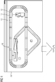
- FIG. 1 shows a schematic representation of a production system 10.
- the production system 10 is a baggage conveyor system of an airport.
- a load calculator 16 is used.
- the load calculating means 16 may be provided by a corresponding simulation program which is executed on a computer, a microprocessor, an ASIC or the like.
- a simulation program for example, the program Plant Simulation can be used.
- the production system 10 is subdivided into a plurality of regions 12 or sections.
- the individual regions 12 can have different geometric dimensions.
- Each of the areas 12 of the production system 10 may be assigned a speed or an acceleration of the belt of the baggage handling system.
- each region 12 can be assigned a length, a width and a geometric shape.
- a load profile 18 of the production system 10 can be determined.
- the load profile 18 is determined as a function of operating variables of the production system 10, which include a speed v, an acceleration a, a basic weight m 0 of the production system and / or a weight m L of a load moved with the production system.
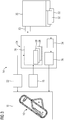
- FIG. 3 is another illustration 14 illustrating the method of determining power consumption of the production system 10.
- the previously described load calculation device 16 is required with which the load profile 18 of the production system 10 is determined.
- the load profile 18 can be determined, for example, for one day (86400 seconds). It can for predetermined time intervals, z. B. one second, each operating variables the individual areas 12 of the production system 10 are determined.
- the energy calculator 20 may be provided by a corresponding program run on a computer, a microprocessor, an ASIC, or the like.
- the program SIZER can be used.
- an electromechanical model 22 is deposited.
- the electromechanical model 22 may include technical, electrical and / or geometric parameters of the electric drives, converters, starters or the like. This information can be determined by physical measurements.
- the electromechanical model 22 may include information about the dimensions of the individual regions 12 of the production system 10. Thus, the length, the width and optionally a spatial arrangement of the luggage belt can be stored.
- the electromechanical model 22 is used as a reference. On the one hand, the data of the electromechanical model 22 are fed to the load calculation device 16, on the other hand the data of the electromechanical model 22 are fed to a data calculation device 24.
- the data calculator 24 may be provided by a calculator on which a program such as Matlab or C is run.
- a parameter file 26 is generated, which can be processed by the energy calculation device 20.
- This parameter file 26 is determined by the data calculation device 24 on the basis of the electromechanical model 22.
- a parameter file 26 can be present for each area 12 of the production system 10.
- the Data computation device 24, the data of the load profile 18 and subdivided into several individual files 28, each individual file 28 is assigned to an area 12 of the production system 10.
- FIG. 2 shows that a range 12 of the production system 10 is associated with a parameter file 26.
- the parameter file 26 comprises several lines or entries.
- an entry 38 is assigned to the diameter of a drive roller 40 of the production system 10 in the region 12.
- the energy calculation device 20 is called repeatedly. In this case, the same parameter file 26 is used, but with each program call a new single file 28 is provided, until all individual files 28 are processed with the energy calculation means 20. In order to enable the data calculation device 24 to program the energy calculation device 20, an interface 30 is provided.
- output files 32 are generated with the energy calculation device 20. These output files 32 comprise information about the power consumption in dependence on the electromechanical model 22 and the load profile 18. The output files 32 are analyzed and optimized by the data calculation device 24 in the block 34 and stored as a power model 36. This process is repeated for all areas 12 of the production system 10.
- the energy model 36 is determined for each area 12 of the production system 10.
- the constants K 1 to K 4 describe the so-called power constants for each area 12 of the production system 10.
- the index N in the above equations represents the number of individual files 28 supplied to the energy calculating means 20.
- the N estimates of the energy demand determined with the energy calculator 20 are used to solve the matrix equation.
- a performance table is determined for each area 12 of the production system 10. For this purpose, one of the farm sizes is assumed to be constant. For example, the velocity v is assumed to be constant and the weight m L of the load is determined.
- the load calculation device 16 is expanded in order to be able to determine with it the energy or power consumption of the production system 10 for a time-variable load.
- the load calculator 16 calculates the current power consumption for each area 12 of the production system 10.
- the operating quantities of the production system 10 are used.
- the speed v of a region 12 of the production system 10 is compared with each other at successive times. If the speed v does not change, the power consumption of the production system 10 is determined from the power tables or the simplified equation as a function of the weight m L of the time-variable load.
- the energy consumption is determined using the mathematical equation or the matrix equation.
- the baggage handling system is initially in an idle state and moves at the minimum speed v of 0.3 m / s.
- the speed v of the baggage handling system is accelerated until it reaches the maximum speed of, for example, 2 m / s.
- the acceleration a of the luggage conveyor system can be predetermined.
- the speed v, the acceleration a, the mass m 0 and the weight m L of the load are variables.
- the mathematical equation is used to determine the energy consumption of the baggage handling system or production system 10.
- the performance tables are used to determine the energy consumption as a function of the current total weight.
- the load calculation device 16 can no longer be used to determine the energy consumption. In this case, a complete description of the load profile 18 is output.
- the energy calculator 20 is called again to update the performance tables.
- the load calculator 16 may use the updated performance tables to operate the production system.
Landscapes
- Engineering & Computer Science (AREA)
- Business, Economics & Management (AREA)
- Physics & Mathematics (AREA)
- General Physics & Mathematics (AREA)
- Human Resources & Organizations (AREA)
- Economics (AREA)
- Strategic Management (AREA)
- Entrepreneurship & Innovation (AREA)
- Automation & Control Theory (AREA)
- Quality & Reliability (AREA)
- Theoretical Computer Science (AREA)
- Development Economics (AREA)
- Marketing (AREA)
- Operations Research (AREA)
- Game Theory and Decision Science (AREA)
- Tourism & Hospitality (AREA)
- General Business, Economics & Management (AREA)
- Educational Administration (AREA)
- General Engineering & Computer Science (AREA)
- Health & Medical Sciences (AREA)
- Artificial Intelligence (AREA)
- Computer Vision & Pattern Recognition (AREA)
- Evolutionary Computation (AREA)
- Medical Informatics (AREA)
- Software Systems (AREA)
- Power Engineering (AREA)
- Management, Administration, Business Operations System, And Electronic Commerce (AREA)
- Feedback Control In General (AREA)
Description
- Die vorliegende Erfindung betrifft ein Verfahren zum Ermitteln eines Energieverbrauchs eines Produktionssystems. Überdies betrifft die vorliegende Erfindung ein Verfahren zum Betreiben eines Produktionssystems.
- Produktionssysteme werden momentan während einer sehr frühen Designphase simuliert, um den Durchsatz und die Effizienz zu erhöhen. Zu diesem Zweck werden beispielsweise Simulationsprogramme wie Plant Simulation von Technomatrix/Siemens verwendet. Solche Programme entwickeln ein Modell für die geplante Anlage bzw. das Produktionssystem, mit dem ein schnelles Simulieren und Testen von verschiedenen Regelstrategien ermöglicht wird. Die Ergebnisse der Simulation werden dazu genutzt, um das Layout des Produktionssystems und Regelstrategien während des Entwurfs des Produktionssystems herauszufinden.
- Mit den momentan verwendeten Simulationsprogrammen kann ein lastabhängiger Energieverbrauch allerdings nicht ermittelt werden. Während des Entwurfs des Produktionssystems wird der Energieverbrauch "von Hand" abgeschätzt, was üblicherweise zu einer beträchtlichen Überschätzung des Energieverbrauchs führt. Darüber hinaus ist eine Optimierung des Betriebs des Produktionssystems, um den Energieverbrauch zu reduzieren mit den zuvor genannten Programmen nicht möglich. Insbesondere im Hinblick auf Umweltschutz und steigende Energiepreise ist dies aber ein wichtiger Aspekt.
- In dem Artikel "Planung energieeffizienter Produktionssysteme" von N. Weinert, veröffentlicht in ZWF, Jahrg. 105, 2010, ist beschrieben, dass bei einem Produktionssystem unterschiedliche Betriebszustände, wie der Hochlauf, der Warmlauf, Wartezustände, der Bearbeitungs- bzw. Prozesszustand oder ein Abschaltvorgang auftreten können. Diese Betriebszustände, die einen unterschiedlichen Energiebedarf aufweisen, werden entsprechenden Blöcken zugeordnet, die modelliert und simuliert werden.
- Aus der
DE 297 07 245 U1 ist bereits eine Regelung eines Förderbands für Massengut im industriellen Einsatz bekannt, bei der eine Einsparung des Energieverbrauchs erreicht wird, indem anhand eines vorgegebenen Lastprofils der Energiebedarf berechnet wird und eine Optimierung beispielsweise anhand der Anpassung der Geschwindigkeit des Förderbands erreicht wird. Es ist Aufgabe der vorliegenden Erfindung, einen Weg aufzuzeigen, wie ein Produktionssystem energieeffizienter geplant und betrieben werden kann. - Diese Aufgabe wird durch ein Verfahren gemäß Patentanspruch 1 und durch ein Verfahren gemäß Patentanspruch 9 gelöst. Vorteilhafte Weiterbildungen der vorliegenden Erfindung sind in den Unteransprüchen angegeben.
- Das erfindungsgemäße Verfahren zum Bestimmen eines Energieverbrauchs eines Produktionssystems umfasst die folgenden Schritte:
- a) Bestimmen eines Lastprofils des Produktionssystems in Abhängigkeit von Betriebsgrößen des Produktionssystems, welche eine Geschwindigkeit, eine Beschleunigung, ein Grundgewicht des Produktionssystems und/oder ein Gewicht der Last beschreiben mit einer Lastberechnungseinrichtung,
- b) Abschätzen eines Energiebedarfs des Produktionssystems anhand des bestimmten Lastprofils und eines elektromechanischen Modells des Produktionssystems mit einer Energieberechnungseinrichtung,
- c) Bestimmen eines Energiemodells des Produktionssystems anhand des abgeschätzten Energiebedarfs, wobei zumindest eine der Betriebsgrößen als konstant angenommen wird und in Abhängigkeit von den nicht als konstant angenommenen Betriebsgrößen eine Leistungstabelle bestimmt wird und
- d) Bestimmen des Energieverbrauchs des Produktionssystems mit der Lastberechnungseinrichtung in Abhängigkeit von dem Energiemodell und einer mit dem Produktionssystem transportierten und/oder bearbeiteten Last.
- Mit dem erfindungsgemäßen Verfahren kann in vorteilhafter Weise der Energieverbrauch des Produktionssystems abgeschätzt werden. Unter dem Begriff Produktionssystem soll im Folgenden jede Anlage, Produktionsanlage oder dergleichen verstanden werden. Insbesondere kann das Produktionssystem ein Förderband umfassen, auf dem eine Last bewegt bzw. transportiert wird. Zunächst wird ein zeitabhängiges Lastprofil des Produktionssystems mit der Lastberechnungseinrichtung bestimmt. Die Lastberechnungseinrichtung kann eine Recheneinrichtung, wie einen Computer, ein Mikroprozessor oder dergleichen, umfassen, auf dem ein Simulationsprogramm für ein Produktionssystem, wie z. B. Plant Simulation, zum Ablauf gebracht wird. Dabei werden realistische Annahmen bezüglich des Durchsatzes zugrunde gelegt. Anschließend wird ein Energiebedarf des Produktionssystems mit einer Energieberechnungseinrichtung ermittelt. Die Energieberechnungseinrichtung kann eine Recheneinrichtung, wie einen Computer, ein Mikroprozessor oder dergleichen, umfassen, auf dem ein Programm zum Ablauf gebracht wird, mit dem die Leistung eines Systems abgeschätzt werden kann. Ein solches Programm kann beispielsweise das Programm SIZER der Firma Siemens sein.
- Bevorzugt wird das Produktionssystem in einzelne Bereiche unterteilt und das Verfahren wird für jeden der Bereiche durchgeführt. Somit kann der Energieverbrauch besonders exakt in Abhängigkeit von der Ausgestaltung des Produktionssystems bestimmt werden. Dabei können Bereiche des Produktionssystems, die gleich sind, nur einmal berechnet werden. Damit kann der Energieverbrauch des Produktionssystems besonders effizient bestimmt werden.
- In einer Ausgestaltung wird in Schritt a) das Lastprofil in Abhängigkeit von Betriebsgrößen des Produktionssystems, welche eine Geschwindigkeit, eine Beschleunigung, ein Grundgewicht des Produktionssystems und/oder ein Gewicht der Last beschreiben, bestimmt. Das Lastprofil wird dabei insbesondere für jeden Bereich des Produktionssystems ermittelt. Dabei werden die Geschwindigkeit bzw. die Beschleunigung des Produktionssystems oder eines Teils des Produktionssystems und das Gewicht der mit dem Produktionssystem transportierten Güter berücksichtigt. Im Anschluss kann das Lastprofil analysiert und gegebenenfalls in ein anderes Datenformat überschrieben werden. Beim Übertragen in ein anderes Datenformat kann die Datei, die Informationen über das Lastprofil umfasst, auch in mehrere Einzeldateien unterteilt werden. Dies ist insbesondere günstig, wenn das Lastprofil über einen längeren Zeitraum, beispielsweise einen Tag, ermittelt wurde.
- Bevorzugt wird in Schritt b) das elektromechanische Modell in Abhängigkeit von Kenngrößen von Antriebseinrichtungen des Produktionssystems und den Abmessungen des Produktionssystems bestimmt. Das elektromechanische Modell kann diejenigen Parameter umfassen, mit denen das elektromechanische System des Produktionssystems ausreichend beschrieben werden kann. Das elektromechanische Modell kann Informationen zu den Typen der verwendeten elektrischen Maschinen, Startern, Wandlern, Ein-/Ausgabeelementen oder dergleichen umfassen. Zudem kann das elektromechanische Modell Informationen über die Länge und Breite der einzelnen Bereiche des Produktionssystems umfassen.
- In einer weiteren Ausgestaltung wird in Schritt c) das Energiemodell in Abhängigkeit von den Betriebsgrößen des Produktionssystems bestimmt. Dazu wird bevorzugt eine mathematische Gleichung aufgestellt, mit der die benötigte Leistung bzw. Energie des Produktionssystems oder Bereichen des Produktionssystems modelliert werden kann. Zusätzlich kann ein mathematisches Modell entwickelt werden, in dem für jede Variable in der mathematischen Gleichung der Anteil an der insgesamt verbrauchten Leistung bestimmt wird. Das Energiemodell kann in allgemeiner Form mit folgender Gleichung dargestellt werden:

- Dabei beschreiben die Variablen Vi1 bis Vin die Geschwindigkeit bzw. die Beschleunigung der einzelnen Bereiche des Produktionssystems und die Last, die mit den jeweiligen Bereichen des Produktionssystems transportiert wird. Diese Variablen beschreiben den Energieverbrauch in dem physikalischen System. j ist eine reelle Zahl, mit der die Ordnung der jeweiligen Variablen angegeben wird. Zwischen den Variablen, beispielsweise der Geschwindigkeit und der Beschleunigung, kann ein Zusammenhang vorliegen. Die Konstanten K1 bis Kn beschreiben die sogenannten Leistungskonstanten.
- Das mit der Lastberechnungseinrichtung bestimmte Lastprofil kann in m Einzeldateien unterteilt werden. Die Einzeldateien können der Reihen nach der Energieberechnungseinrichtung zugeführt werden. Zusammen mit den Informationen über das elektromechanischen Systems kann mit der Energieberechnungseinrichtung für jeden Bereich des Produktionssystems die benötigt Energie bzw. Leistung abgeschätzt werden. Anhand der m Schätzwerte für die Leistung kann die folgende Matrixgleichung aufgestellt werden:

- Die Matrixgleichung kann nach den Leistungsfaktoren K1 bis Kn aufgelöst werden, um diese zu ermitteln.
- Bevorzugt wird in Schritt c) zumindest eine der der Betriebsgrößen als konstant angenommen und in Abhängigkeit von den nicht als konstant angenommenen Betriebsgrößen wird eine Leistungstabelle bestimmt. Wenn die Geschwindigkeit des Produktionssystems für eine bestimmte Zeitdauer konstant ist, nimmt die Beschleunigung des Produktionssystems den Wert Null an. Damit kann das Energiemodell mit der Energieberechnungseinrichtung nur noch in Abhängigkeit von dem Gewicht des Produktionssystems und/oder der bewegten Last ermittelt werden. Wenn die Variablen in der Gleichung für das Energiemodell für einen bestimmten Zeitraum als konstant angenommen werden, kann die Gleichung in Abhängigkeit von einer Variablen umgeschrieben werden:

- Dabei sind C1 und C2 Konstanten, die mit der Energieberechnungseinrichtung ermittelt werden können. Dazu können die Konstanten für jeden möglichen Wert der Variablen abgeschätzt werden. Die Ergebnisse der Abschätzung können in einer oder mehreren Leistungstabellen für jeden Bereich des Produktionssystems gespeichert werden.
- In einer Ausführungsform wird zumindest eine der Betriebsgrößen des Produktionssystems anhand von Messungen ermittelt. Zu diesem Zweck können physikalische Messungen an dem Produktionssystem im Betrieb durchgeführt werden. Mit den Daten der Messungen können die Betriebsgrößen besonders genau ermittelt werden. Auf Grundlage dieser Messungen kann der Energieverbrauch des Produktionssystems exakt bestimmt werden.
- Bevorzugt wird in Schritt d) der Energieverbrauch des Produktionssystems in Abhängigkeit von dem Energiemodell oder der Leistungstabelle bestimmt. Die Lastberechnungseinrichtung werden die Leistungstabellen und die Energiemodell zugeführt. Anstelle des Energiemodells können der Lastberechnungseinrichtung auch die Leistungskonstanten zugeführt werden. Mit den Leistungstabellen und/oder dem Energiemodell kann mit der Lastberechnungseinrichtung der Energieverbrauch des Produktionssystems dynamische in Abhängigkeit von einer zeitlich variablen Last, die mit dem Produktionssystem befördert wird, ermittelt werden. Damit wird es ermöglicht, die momentane Leistung, die durchschnittliche Leistung und die Energie zu berechnen. Die durchschnittliche Leistung kann für ein vorgegebenes Zeitintervall, beispielsweise eine Sekunde, berechnet werden:


- Beim Simulieren des Produktionssystems berechnet die Lastberechnungseinrichtung anhand der Betriebsgrößen den Energieverbrauch des Produktionssystems. Die durchschnittliche Leistung und die Energie werden für n Zeitintervalle berechnet.
- Damit kann eine einfache Berechnung des Energieverbrauchs des Produktionssystems ermöglicht werden, bei der weinig Ressourcen benötigt werden, um das Energiemodell in einem Speicher der Lastberechnungseinrichtung zu speichern. Die Lastberechnungseinrichtung wird durch die zusätzliche Berechnung des Energieverbrauchs in Bezug auf die Rechenleistung nicht negativ beeinflusst. Zudem kann der Energieverbrauch des Produktionssystems schnell und zuverlässig ermittelt werden.
- Weiterhin ist es vorteilhaft, wenn in Schritt d) zum Bestimmen des Energieverbrauchs zumindest eine der Betriebsgrößen an zumindest zwei aufeinanderfolgenden Zeitpunkten untersucht wird. Mit der Lastberechnungseinrichtung kann beispielsweise die Geschwindigkeit des Produktionssystems zu zwei aufeinander folgenden Zeitpunkten berücksichtigt werden, um den Energieverbrauch des Produktionssystems zu bestimmen. Wenn sich die Geschwindigkeit bei zumindest zwei aufeinanderfolgenden Zeitpunkten nicht ändert, können die Werte für die Last aus der Leistungstabelle für die jeweiligen Bereiche des Produktionssystems herangezogen werden, um den Energieverbrauch zu bestimmen. Wenn sich die Geschwindigkeit bei zumindest zwei aufeinanderfolgenden Zeitpunkten ändert, kann das Energiemodell zur Berechnung des Energieverbrauchs genutzt werden. Somit kann ein hybrider Ansatz bereitgestellt werden, um den Energieverbrauch des Produktionssystems zu ermitteln. Es kann schätzungsweise davon ausgegangen werden, dass in 70% der Fälle die Leistungstabellen zur Berechnung des Energieverbrauchs herangezogen werden. Somit ist der zusätzliche Bedarf an Ressourcen, der durch die Speicherung der Leistungstabellen belegt wird, begründet. Des Weiteren kann der Energieverbrauch zuverlässiger bestimmt werden.
- Für den Fall, dass für ein geplantes Produktionssystem oder Bereiche davon, der Energieverbrauch mit der Lastberechnungseinrichtung nicht bestimmt werden kann, wird das Verfahren bzw. die Simulation angehalten und eine entsprechende Nachricht ausgegeben. Zudem kann durch eine Bedieneingabe auf die Energieberechnungseinrichtung zuzugreifen werden, wodurch mit der Energieberechnungseinrichtung die fehlenden Variablen bzw. Parameter für das Energiemodell oder die Leistungstabelle ermittelt werden können.
- Bei dem erfindungsgemäßen Verfahren zum Betreiben eines Produktionssystems wird das Produktionssystem in Abhängigkeit von dem Energieverbrauch betrieben, der mit dem zuvor beschriebenen Verfahren bestimmt wurde. Dabei kann das Produktionssystem mit der Lastberechnungseinrichtung angesteuert werden. Somit kann das Produktionssystem besonderes energieeffizient betrieben werden. Beim Simulieren des Produktionssystems berechnet die Lastberechnungseinrichtung anhand der Betriebsgrößen den Energieverbrauch des Produktionssystems. Die durchschnittliche Leistung und die Energie werden für n Zeitintervalle berechnet.
- Die vorliegende Erfindung wird nun anhand der beigefügten Zeichnungen näher erläutert. Dabei zeigen:
- FIG 1
- eine schematische Darstellung eines Produktionssystems;
- FIG 2
- eine schematische Darstellung zur Verdeutlichung eines Verfahrens zum Bestimmen eines Energieverbrauchs des Produktionssystems; und
- FIG 3
- eine schematische Darstellung zur Verdeutlichung des Verfahrens zum Bestimmen des Energieverbrauchs des Produktionssystems in einer weiteren Ausführungsform.
- Die nachfolgend näher geschilderten Ausführungsbeispiele stellen bevorzugte Ausführungsformen der vorliegenden Erfindung dar.
-
FIG 1 zeigt eine schematische Darstellung eines Produktionssystems 10. Im hier dargestellten Ausführungsbeispiel ist das Produktionssystems 10 eine Gepäckförderanlage eines Flughafens. Um die Durchsatz des Produktionssystems 10 berechnen zu können, wird eine Lastberechnungseinrichtung 16 verwendet. Die Lastberechnungseinrichtung 16 kann durch ein entsprechendes Simulationsprogramm bereitgestellt werden, das auf einem Computer, einem Mikroprozessor, einem ASIC oder dergleichen zum Ablauf gebracht wird. Als Simulationsprogramm kann beispielsweise das Programm Plant Simulation verwendet werden. - Um die Produktionssystem 10 berechnen bzw. simulieren zu können, wird das Produktionssystem 10 in mehrere Bereiche 12 bzw. Abschnitte unterteilt. Die einzelnen Bereiche 12 können dabei unterschiedliche geometrische Abmessungen aufweisen. Jedem der Bereiche 12 des Produktionssystems 10 kann eine Geschwindigkeit bzw. eine Beschleunigung des Bands der Gepäckförderanlage zugeordnet werden. Zudem kann jedem Bereich 12 eine Länge, eine Breite und eine geometrische Formgebung zugeordnet werden.
- Mit der Lastberechnungseinrichtung 16 kann ein Lastprofil 18 des Produktionssystems 10 ermittelt werden. Das Lastprofil 18 wird in Abhängigkeit von Betriebsgrößen des Produktionssystems 10, welche eine Geschwindigkeit v, eine Beschleunigung a, ein Grundgewicht m0 des Produktionssystems und/oder ein Gewicht mL einer mit dem Produktionssystem bewegten Last umfassen, bestimmt.
-
FIG 3 zeigt eine weitere Darstellung 14, die das Verfahren zum Bestimmen eines Energieverbrauchs des Produktionssystems 10 verdeutlicht. Zur Durchführung des Verfahrens wird die zuvor beschriebene Lastberechnungseinrichtung 16 benötigt, mit der das Lastprofil 18 des Produktionssystems 10 ermittelt wird. Das Lastprofil 18 kann beispielsweise für einen Tag (86400 Sekunden) ermittelt werden. Dabei können für vorgegebene Zeitintervalle, z. B. eine Sekunde, jeweils die Betriebsgrößen der einzelnen Bereiche 12 des Produktionssystems 10 ermittelt werden. - Darüber hinaus wird zur Durchführung des Verfahrens eine Energieberechnungseinrichtung 20 benötigt. Die Energieberechnungseinrichtung 20 kann durch einen ein entsprechendes Programm bereitgestellt werden, das auf einem Computer, einem Mikroprozessor, einem ASIC oder dergleichen zum Ablauf gebracht wird. Als Programm kann beispielsweise das Programm SIZER verwendet werden.
- Für das Produktionssystem 10 ist ein elektromechanisches Modell 22 hinterlegt. Dazu sind bevorzugt Informationen über die Komponenten des Produktionssystems 10 für jeden Bereich 12 des Produktionssystems 10 in einer Tabelle gespeichert. Das elektromechanische Modell 22 kann technische, elektrische und/oder geometrische Kenngrößen der elektrischen Antriebe, Umrichter, Starter oder dergleichen umfassen. Diese Informationen können durch physikalische Messungen ermittelt werden. Überdies kann das elektromechanische Modell 22 Informationen über die Abmessungen der einzelnen Bereiche 12 des Produktionssystems 10 umfassen. So können die Länge, die Breite und gegebenenfalls einer räumlichen Anordnung des Gepäckbands gespeichert sein. Das elektromechanische Modell 22 wird als Referenz genutzt. Zum einem werden die Daten des elektromechanischen Modells 22 der Lastberechnungseinrichtung 16 zugeführt, zum anderen werden die Daten des elektromechanischen Modells 22 einer Datenberechnungseinrichtung 24 zugeführt.
- Die Datenberechnungseinrichtung 24 kann durch eine Recheneinrichtung bereitgestellt werden, auf dem ein Programm wie Matlab oder C zu Ablauf gebracht wird. Mit der Datenberechnungseinrichtung 24 wird eine Parameterdatei 26 erzeugt, die von der Energieberechnungseinrichtung 20 verarbeitet werden kann. Diese Parameterdatei 26 wird von der Datenberechnungseinrichtung 24 anhand des elektromechanischen Modells 22 bestimmt. Dabei kann eine Parameterdatei 26 für jeden Bereich 12 des Produktionssystems 10 vorliegen. Zudem empfängt die Datenberechnungseinrichtung 24 die Daten des Lastprofils 18 und unterteilt diese in mehrere Einzeldateien 28, wobei jede Einzeldatei 28 einem Bereich 12 des Produktionssystems 10 zugeordnet ist.
-
FIG 2 zeigt, das einem Bereich 12 des Produktionssystems 10 eine Parameterdatei 26 zugeordnet ist. Die Parameterdatei 26 umfasst mehrere Zeilen bzw. Einträge. Dabei ist ein Eintrag 38 dem Durchmesser einer Antriebsrolle 40 des Produktionssystems 10 in dem Bereich 12 zugeordnet. - Um den Energiebedarf der einzelnen Bereiche 12 des Produktionssystems 10 zu bestimmen, wird die Energieberechnungseinrichtung 20 wiederholt aufgerufen. Dabei wird die gleiche Parameterdatei 26 verwendet, aber bei jedem Programmaufruf wird eine neue Einzeldatei 28 bereitgestellt, solange bis alle Einzeldateien 28 mit der Energieberechnungseinrichtung 20 verarbeitet sind. Um mit der Datenberechnungseinrichtung 24 einen Programmaufruf der Energieberechnungseinrichtung 20 zu ermöglichen, ist eine Schnittstelle 30 vorgesehen.
- Nach jedem Programmaufruf werden mit der Energieberechnungseinrichtung 20 Ausgabedateien 32 erzeugt. Diese Ausgabedateien 32 umfassen eine Information über den Leistungs- bzw. Energieverbrauch in Abhängigkeit dem elektromechanischen Modell 22 und dem Lastprofil 18. Die Ausgabedateien 32 werden an die Datenberechnungseinrichtung 24, dort in dem Block 34 analysiert und optimiert und als Energiemodell 36 gespeichert. Dieser Prozess wird für alle Bereiche 12 des Produktionssystems 10 wiederholt.
- Im Anschluss wird das Energiemodell 36 für jeden Bereich 12 des Produktionssystems 10 ermittelt. Dazu werden zunächst die Betriebsgrößen, die den Energieverbrauch des Produktionssystems 10 beeinflussen, gemäß der nachfolgenden Gleichung spezifiziert:

- Dabei beschreiben die Konstanten K1 bis K4 dies sogenannten Leistungskonstanten für jeden Bereich 12 des Produktionssystems 10. Um die Leistungskonstanten K1 bis K4 berechnen zu können das mathematische Modell auch als Matrixgleichung dargestellt werden:

- Dabei repräsentiert der Index N in den obigen Gleichungen die Anzahl der Einzeldateien 28, die der Energieberechnungseinrichtung 20 zugeführt werden. Um die Leistungskonstanten K1 bis K4 zu berechnen, werden die N Schätzwerte des Energiebedarfs, die mit der Energieberechnungseinrichtung 20 ermittelt wurden, dazu verwendet, um die Matrixgleichung zu lösen.
- Zusätzlich wird für jeden Bereich 12 der Produktionssystems 10 eine Leistungstabelle ermittelt. Zu diesem Zweck wird eine der Betriebsgrößen als konstant angenommen. Beispielsweise wird die Geschwindigkeit v als konstant angenommen und das Gewicht mL der Last bestimmt. Alternativ zu den Leistungstabellen kann eine vereinfachte Gleichung bereitgestellt werden:

- In einem letzten Schritt wird die Lastberechnungseinrichtung 16 erweitert, um mit ihr den Energie- bzw. Leistungsverbrauch des Produktionssystems 10 für eine zeitlich variable Last ermitteln zu können. Wenn die Berechnung bzw. Simulation gestartet wird, berechnet die Lastberechnungseinrichtung 16 den aktuellen Energie- bzw. Leistungsverbrauch für jeden Bereich 12 des Produktionssystems 10. Zu diesem Zweck werden die Betriebsgrößen des Produktionssystems 10 verwendet. Dabei wird die Geschwindigkeit v eines Bereichs 12 des Produktionssystems 10 zu aufeinanderfolgenden Zeitpunkten miteinander verglichen. Wenn sich die Geschwindigkeit v nicht ändert, wird anhand der Leistungstabellen oder der vereinfachten Gleichung der Energieverbrauch des Produktionssystems 10 in Abhängigkeit von dem Gewicht mL der zeitlich variablen Last ermittelt. Wenn sich die Geschwindigkeit v ändert, wird der Energieverbrauch anhand der mathematischen Gleichung oder der Matrixgleichung ermittelt.
- Beispielsweise ist das Gepäckfördersystem zunächst in einem Ruhezustand und bewegt sich mit der minimalen Geschwindigkeit v von 0,3 m/s. Wenn ein Gepäckstück eintrifft, wird die Geschwindigkeit v des Gepäckfördersystems beschleunigt, bis es die Maximalgeschwindigkeit von beispielsweise 2 m/s erreicht. Die Beschleunigung a des Gepäckfördersystems kann dabei vorgegeben sein. Während der Beschleunigung sind die Geschwindigkeit v, die Beschleunigung a, die Masse m0 und das Gewicht mL der Last Variablen. In diesem Fall wird die mathematische Gleichung verwendet, um den Energieverbrauch des Gepäckfördersystems bzw. des Produktionssystems 10 zu ermitteln. Wenn das Gepäckfördersystem allerdings die maximale Geschwindigkeit v erreicht hat, ist die einzige Variable das Gesamtgewicht (m0 + mL). In diesem Fall werden die Leistungstabellen herangezogen, um den Energieverbrauch in Abhängigkeit von dem momentanen Gesamtgewicht zu ermitteln.
- Im Anschluss daran, wenn kein Gepäckstück transportiert wird und das Gesamtgewicht den Wert Null annimmt, wird mit der Lastberechnungseinrichtung 16 ein Signal ausgegeben, wodurch die Geschwindigkeit v des Produktionssystems 10 in Schritten reduziert wird. Bis zum Erreichen der Minimalgeschwindigkeit wird die mathematische Gleichung herangezogen, um den momentanen Energieverbrauch zu bestimmen.
- Wenn beispielsweise die Anzahl der Gepäckstücke und somit die Gesamtlast auf den einzelnen Bereichen 12 verändert wird, kann es der Fall sein, dass mit der Lastberechnungseinrichtung 16 der Energieverbrauch nicht mehr ermittelt werden kann. In diesem Fall wird eine komplette Beschreibung des Lastprofils 18 ausgegeben. Die Energieberechnungseinrichtung 20 wird nochmals aufgerufen, um die Leistungstabellen zu aktualisieren. Die Lastberechnungseinrichtung 16 kann die aktualisierten Leistungstabellen nutzen, um das Produktionssystem zu betreiben.
-
- 10
- Produktionssystem
- 12
- Bereich
- 14
- Darstellung
- 16
- Lastberechnungseinrichtung
- 18
- Lastprofil
- 20
- Energieberechnungseinrichtung
- 22
- elektromechanisches Modell
- 24
- Datenberechnungseinrichtung
- 26
- Parameterdatei
- 28
- Einzeldatei
- 30
- Schnittstelle
- 32
- Ausgabedatei
- 34
- Block
- 36
- Energiemodell
- 38
- Eintrag
- 40
- Antriebsrolle
- a
- Beschleunigung
- m0
- Grundgewicht
- mL
- Gewicht
- v
- Geschwindigkeit
Claims (9)
- Verfahren zum Bestimmen eines Energieverbrauchs eines Produktionssystems (10) mit den Schritten:a) Bestimmen eines Lastprofils (18) des Produktionssystems (10) in Abhängigkeit von Betriebsgrößen des Produktionssystems, welche eine Geschwindigkeit, eine Beschleunigung, ein Grundgewicht des Produktionssystems und/oder ein Gewicht der Last beschreiben mit einer Lastberechnungseinrichtung (16),b) Abschätzen eines Energiebedarfs des Produktionssystems (10) anhand des bestimmten Lastprofils (18) und eines elektromechanischen Modells (22) des Produktionssystems (10) mit einer Energieberechnungseinrichtung (20),c) Bestimmen eines Energiemodells (36) des Produktionssystems (10) anhand des abgeschätzten Energiebedarfs, wobei zumindest eine der Betriebsgrößen als konstant angenommen wird und in Abhängigkeit von den nicht als konstant angenommenen Betriebsgrößen eine Leistungstabelle bestimmt wird undd) Bestimmen des Energieverbrauchs des Produktionssystems (10) mit der Lastberechnungseinrichtung (16) in Abhängigkeit von dem Energiemodell (36) und einer mit dem Produktionssystem (10) transportierten und/oder bearbeiteten Last.
- Verfahren nach Anspruch 1, dadurch gekennzeichnet, dass das Produktionssystem (10) in einzelne Bereiche (12) unterteilt wird und das Verfahren für jeden der Bereiche (12) durchgeführt wird.
- Verfahren nach Anspruch 1 oder 2, dadurch gekennzeichnet, dass in Schritt a) das Lastprofil (18) in Abhängigkeit von Betriebsgrößen des Produktionssystems (10), welche eine Geschwindigkeit (v), eine Beschleunigung (a), ein Grundgewicht (m0) des Produktionssystems (10) und/oder ein Gewicht (mL) der Last beschreiben, bestimmt wird.
- Verfahren nach einem der vorhergehenden Ansprüche, dadurch gekennzeichnet, dass in Schritt b) das elektromechanische Modell (22) in Abhängigkeit von Kenngrößen von Antriebseinrichtungen des Produktionssystems (10) und den Abmessungen des Produktionssystems (10) bestimmt wird.
- Verfahren nach einem der vorhergehenden Ansprüche, dadurch gekennzeichnet, dass in Schritt c) das Energiemodell (36) in Abhängigkeit von den Betriebsgrößen des Produktionssystems (10) bestimmt wird.
- Verfahren nach einem der vorhergehenden Ansprüche, dadurch gekennzeichnet, dass zumindest eine der Betriebsgrößen des Produktionssystems (10) anhand von Messungen ermittelt wird.
- Verfahren nach Anspruch 1, dadurch gekennzeichnet, dass in Schritt d) der Energieverbrauch des Produktionssystems (10) in Abhängigkeit von dem Energiemodell (36) oder der Leistungstabelle bestimmt wird.
- Verfahren nach einem der vorhergehenden Ansprüche, dadurch gekennzeichnet, dass in Schritt d) zum Bestimmen des Energieverbrauchs zumindest eine der Betriebsgrößen an zumindest zwei aufeinanderfolgende Zeitpunkten untersucht wird.
- Verfahren zum Betreiben eines Produktionssystems (10), dadurch gekennzeichnet, dass das Produktionssystem (10) in Abhängigkeit von einem mit einem Verfahren nach einem der vorhergehenden Ansprüche bestimmten Energieverbrauch betrieben wird.
Applications Claiming Priority (1)
| Application Number | Priority Date | Filing Date | Title |
|---|---|---|---|
| PCT/EP2012/059015 WO2013170884A1 (de) | 2012-05-15 | 2012-05-15 | Verfahren zum ermitteln und optimieren eines energieverbrauchs eines produktionssystems |
Publications (2)
| Publication Number | Publication Date |
|---|---|
| EP2825923A1 EP2825923A1 (de) | 2015-01-21 |
| EP2825923B1 true EP2825923B1 (de) | 2017-01-18 |
Family
ID=46125437
Family Applications (1)
| Application Number | Title | Priority Date | Filing Date |
|---|---|---|---|
| EP12722125.7A Not-in-force EP2825923B1 (de) | 2012-05-15 | 2012-05-15 | Verfahren zum ermitteln und optimieren eines energieverbrauchs eines produktionssystems |
Country Status (5)
| Country | Link |
|---|---|
| US (1) | US10718800B2 (de) |
| EP (1) | EP2825923B1 (de) |
| CN (1) | CN104303119B (de) |
| ES (1) | ES2617482T3 (de) |
| WO (1) | WO2013170884A1 (de) |
Families Citing this family (4)
| Publication number | Priority date | Publication date | Assignee | Title |
|---|---|---|---|---|
| DE102013216069A1 (de) | 2013-08-14 | 2015-02-19 | Siemens Aktiengesellschaft | Verfahren zum energieeffizienten Betrieb von Automatisierungsgeräten eines industriellen Automatisierungssystems und Simulationssystem |
| DE102014203764A1 (de) | 2014-02-28 | 2015-09-03 | Siemens Aktiengesellschaft | Verfahren zur energieverbrauchsbasierten Auslegung einer technischen Anlage |
| DE102015211944A1 (de) * | 2015-06-26 | 2016-12-29 | Zf Friedrichshafen Ag | Verfahren und Vorrichtung zur Ermittlung eines energieeffizienten Arbeitspunkts |
| US10345795B2 (en) | 2015-12-22 | 2019-07-09 | Rockwell Automation Technologies, Inc. | Systems and methods to enhance machine designs and production rate schedules for minimized energy cost |
Family Cites Families (13)
| Publication number | Priority date | Publication date | Assignee | Title |
|---|---|---|---|---|
| US4580698A (en) * | 1983-05-25 | 1986-04-08 | Pebco, Inc. | Automatically adjustable continuous feeder system |
| DE29707245U1 (de) * | 1997-04-22 | 1997-08-21 | Lausitzer Braunkohle AG (LAUBAG), 01968 Senftenberg | Regelung für ein Hochleistungsförderband im industriellen Einsatz |
| DE19908317A1 (de) * | 1999-02-26 | 2000-10-05 | Pc Soft Gmbh | Verfahren zur Offline- und/oder Onlineüberwachung und Grundlage zur Merkmalgenerierung einer Optimierung sowie Bearbeitung des Zustandes einer Gurtförderanlage |
| US6990591B1 (en) | 1999-11-18 | 2006-01-24 | Secureworks, Inc. | Method and system for remotely configuring and monitoring a communication device |
| US20030055677A1 (en) * | 2001-09-14 | 2003-03-20 | Automated Energy, Inc. | Utility monitoring and management system |
| EP1429219A1 (de) * | 2002-12-10 | 2004-06-16 | Abb Research Ltd. | Entwurf von Komponenten mit dicken Wanden für Kraftwerken mit Hilfe von Risswachstummodellen |
| WO2008039759A2 (en) * | 2006-09-25 | 2008-04-03 | Intelligent Management Systems Corporation | System and method for resource management |
| US7872368B2 (en) | 2008-10-24 | 2011-01-18 | The Boeing Company | Intelligent energy management architecture |
| JP4703736B2 (ja) | 2009-03-02 | 2011-06-15 | 株式会社東芝 | エネルギー管理システム及び方法 |
| US9129231B2 (en) * | 2009-04-24 | 2015-09-08 | Rockwell Automation Technologies, Inc. | Real time energy consumption analysis and reporting |
| US9005572B2 (en) * | 2009-12-10 | 2015-04-14 | Honeywell International Inc. | Hydrogen generator |
| US20120065793A1 (en) | 2010-02-25 | 2012-03-15 | Kaji Mitsuru | Demand and supply control apparatus, demand and supply control method, and program |
| US9992824B2 (en) * | 2010-10-29 | 2018-06-05 | Goji Limited | Time estimation for energy application in an RF energy transfer device |
-
2012
- 2012-05-15 US US14/399,469 patent/US10718800B2/en not_active Expired - Fee Related
- 2012-05-15 CN CN201280073211.7A patent/CN104303119B/zh not_active Expired - Fee Related
- 2012-05-15 EP EP12722125.7A patent/EP2825923B1/de not_active Not-in-force
- 2012-05-15 ES ES12722125.7T patent/ES2617482T3/es active Active
- 2012-05-15 WO PCT/EP2012/059015 patent/WO2013170884A1/de not_active Ceased
Non-Patent Citations (1)
| Title |
|---|
| None * |
Also Published As
| Publication number | Publication date |
|---|---|
| ES2617482T3 (es) | 2017-06-19 |
| CN104303119A (zh) | 2015-01-21 |
| US10718800B2 (en) | 2020-07-21 |
| WO2013170884A1 (de) | 2013-11-21 |
| US20150120005A1 (en) | 2015-04-30 |
| CN104303119B (zh) | 2016-12-14 |
| EP2825923A1 (de) | 2015-01-21 |
Similar Documents
| Publication | Publication Date | Title |
|---|---|---|
| EP2564049B1 (de) | STEUERGERÄT UND VERFAHREN ZUR BERECHNUNG EINER AUSGANGSGRÖßE FÜR EINE STEUERUNG | |
| EP2952989B1 (de) | Verfahren zur berechnung einer optimierten trajektorie | |
| EP2999998B1 (de) | Methode zur ermittlung eines modells einer ausgangsgrösse eines technischen systems | |
| EP2452232B1 (de) | Verfahren zur optimierung von petri-netz orchestrierten arbeitsabläufen für service-orientierte automatisierungsgeräte in service-orientierten automatisierten systemen | |
| EP3446185B1 (de) | Verfahren und vorrichtung zur gestaltung eines produktionsprozesses zum produzieren eines aus mehreren teilprodukten zusammengesetzten produkts | |
| EP2194432B1 (de) | Scheduling-Verfahren | |
| DE102017006703A1 (de) | Maschinenlerneinrichtung, die einen Strombefehl für einen Motor lernt, Motorsteuereinrichtung und Maschinenlernverfahren | |
| EP3814862B1 (de) | Anordnung und verfahren zur prognose einer restnutzungsdauer einer maschine | |
| EP2607877B1 (de) | Schwerpunktermittlung | |
| EP1623287B1 (de) | Auslegung von werkzeugen und prozessen für die umformtechnik | |
| EP3321754A1 (de) | Verfahren zur optimierung von bewegungsprofilen, computerprogrammprodukt, steuereinrichtung und anlage oder roboter | |
| EP2120143A1 (de) | Verfahren zur Ausführung von Tasks zur Berechnung eines zu simulierenden Signals in Echtzeit | |
| WO2016193305A1 (de) | Verfahren zur berechnung einer optimierten trajektorie | |
| EP3479178A1 (de) | Simulations-basierte regelung eines fertigungssystems unter beruecksichtigung eines vorab berechneten verarbeitungsfensters | |
| EP3061576A1 (de) | Verfahren zur Optimierung eines Bewegungsprofils, Computerprogramm, Steuereinrichtung und technisches System | |
| WO2013170884A1 (de) | Verfahren zum ermitteln und optimieren eines energieverbrauchs eines produktionssystems | |
| EP3356834B1 (de) | Verfahren zum rechnergestützten ermitteln von parametern eines elektrochemischen energiespeichers | |
| DE102020205962B3 (de) | Vorrichtung und Verfahren zum Betreiben eines Prüfstands | |
| DE102023209930A1 (de) | Verfahren zum Bewerten der Sicherheit eines hindernisfreien Raums für ein Ego-Objekt während eines bestimmten Zeitraums unter Verwendung eines Free-Space-Gitters | |
| EP2517129B1 (de) | Verfahren und prozessrechner zur berechnung der zustandsgrössen eines hybriden differential-algebraischen prozessmodells | |
| EP1556811A2 (de) | Vorhersage des termintreuegrads in der serienfertigung | |
| EP2557465B1 (de) | Verfahren und Vorrichtung zur Steuerung eines Bewegungsablaufs eines Maschinenelementes | |
| DE102014203764A1 (de) | Verfahren zur energieverbrauchsbasierten Auslegung einer technischen Anlage | |
| WO2020212100A1 (de) | Verfahren, vorrichtungen und system zum bearbeiten eines werkstücks | |
| WO2020244850A1 (de) | VORRICHTUNG UND VERFAHREN ZUR STEUERUNG KOMPLEXER PRODUKTIONSABFOLGEN IN GROßTECHNISCHEN ANLAGEN INSBESONDERE DER STAHLINDUSTRIE |
Legal Events
| Date | Code | Title | Description |
|---|---|---|---|
| PUAI | Public reference made under article 153(3) epc to a published international application that has entered the european phase |
Free format text: ORIGINAL CODE: 0009012 |
|
| 17P | Request for examination filed |
Effective date: 20141009 |
|
| AK | Designated contracting states |
Kind code of ref document: A1 Designated state(s): AL AT BE BG CH CY CZ DE DK EE ES FI FR GB GR HR HU IE IS IT LI LT LU LV MC MK MT NL NO PL PT RO RS SE SI SK SM TR |
|
| AX | Request for extension of the european patent |
Extension state: BA ME |
|
| DAX | Request for extension of the european patent (deleted) | ||
| 17Q | First examination report despatched |
Effective date: 20151217 |
|
| REG | Reference to a national code |
Ref country code: DE Ref legal event code: R079 Ref document number: 502012009370 Country of ref document: DE Free format text: PREVIOUS MAIN CLASS: G05B0019418000 Ipc: G05B0017020000 |
|
| GRAP | Despatch of communication of intention to grant a patent |
Free format text: ORIGINAL CODE: EPIDOSNIGR1 |
|
| RIC1 | Information provided on ipc code assigned before grant |
Ipc: G05B 17/02 20060101AFI20160715BHEP Ipc: G06Q 10/04 20120101ALI20160715BHEP Ipc: G06Q 10/06 20120101ALI20160715BHEP |
|
| INTG | Intention to grant announced |
Effective date: 20160809 |
|
| GRAS | Grant fee paid |
Free format text: ORIGINAL CODE: EPIDOSNIGR3 |
|
| GRAA | (expected) grant |
Free format text: ORIGINAL CODE: 0009210 |
|
| AK | Designated contracting states |
Kind code of ref document: B1 Designated state(s): AL AT BE BG CH CY CZ DE DK EE ES FI FR GB GR HR HU IE IS IT LI LT LU LV MC MK MT NL NO PL PT RO RS SE SI SK SM TR |
|
| REG | Reference to a national code |
Ref country code: GB Ref legal event code: FG4D Free format text: NOT ENGLISH |
|
| REG | Reference to a national code |
Ref country code: CH Ref legal event code: EP |
|
| REG | Reference to a national code |
Ref country code: AT Ref legal event code: REF Ref document number: 863251 Country of ref document: AT Kind code of ref document: T Effective date: 20170215 |
|
| REG | Reference to a national code |
Ref country code: IE Ref legal event code: FG4D Free format text: LANGUAGE OF EP DOCUMENT: GERMAN |
|
| REG | Reference to a national code |
Ref country code: DE Ref legal event code: R096 Ref document number: 502012009370 Country of ref document: DE |
|
| REG | Reference to a national code |
Ref country code: NL Ref legal event code: MP Effective date: 20170118 |
|
| REG | Reference to a national code |
Ref country code: LT Ref legal event code: MG4D |
|
| REG | Reference to a national code |
Ref country code: ES Ref legal event code: FG2A Ref document number: 2617482 Country of ref document: ES Kind code of ref document: T3 Effective date: 20170619 |
|
| PG25 | Lapsed in a contracting state [announced via postgrant information from national office to epo] |
Ref country code: NL Free format text: LAPSE BECAUSE OF FAILURE TO SUBMIT A TRANSLATION OF THE DESCRIPTION OR TO PAY THE FEE WITHIN THE PRESCRIBED TIME-LIMIT Effective date: 20170118 |
|
| PG25 | Lapsed in a contracting state [announced via postgrant information from national office to epo] |
Ref country code: LT Free format text: LAPSE BECAUSE OF FAILURE TO SUBMIT A TRANSLATION OF THE DESCRIPTION OR TO PAY THE FEE WITHIN THE PRESCRIBED TIME-LIMIT Effective date: 20170118 Ref country code: HR Free format text: LAPSE BECAUSE OF FAILURE TO SUBMIT A TRANSLATION OF THE DESCRIPTION OR TO PAY THE FEE WITHIN THE PRESCRIBED TIME-LIMIT Effective date: 20170118 Ref country code: IS Free format text: LAPSE BECAUSE OF FAILURE TO SUBMIT A TRANSLATION OF THE DESCRIPTION OR TO PAY THE FEE WITHIN THE PRESCRIBED TIME-LIMIT Effective date: 20170518 Ref country code: NO Free format text: LAPSE BECAUSE OF FAILURE TO SUBMIT A TRANSLATION OF THE DESCRIPTION OR TO PAY THE FEE WITHIN THE PRESCRIBED TIME-LIMIT Effective date: 20170418 Ref country code: FI Free format text: LAPSE BECAUSE OF FAILURE TO SUBMIT A TRANSLATION OF THE DESCRIPTION OR TO PAY THE FEE WITHIN THE PRESCRIBED TIME-LIMIT Effective date: 20170118 Ref country code: GR Free format text: LAPSE BECAUSE OF FAILURE TO SUBMIT A TRANSLATION OF THE DESCRIPTION OR TO PAY THE FEE WITHIN THE PRESCRIBED TIME-LIMIT Effective date: 20170419 |
|
| RAP2 | Party data changed (patent owner data changed or rights of a patent transferred) |
Owner name: SIEMENS AKTIENGESELLSCHAFT |
|
| PG25 | Lapsed in a contracting state [announced via postgrant information from national office to epo] |
Ref country code: LU Free format text: LAPSE BECAUSE OF NON-PAYMENT OF DUE FEES Effective date: 20170531 Ref country code: BG Free format text: LAPSE BECAUSE OF FAILURE TO SUBMIT A TRANSLATION OF THE DESCRIPTION OR TO PAY THE FEE WITHIN THE PRESCRIBED TIME-LIMIT Effective date: 20170418 Ref country code: PL Free format text: LAPSE BECAUSE OF FAILURE TO SUBMIT A TRANSLATION OF THE DESCRIPTION OR TO PAY THE FEE WITHIN THE PRESCRIBED TIME-LIMIT Effective date: 20170118 Ref country code: PT Free format text: LAPSE BECAUSE OF FAILURE TO SUBMIT A TRANSLATION OF THE DESCRIPTION OR TO PAY THE FEE WITHIN THE PRESCRIBED TIME-LIMIT Effective date: 20170518 Ref country code: LV Free format text: LAPSE BECAUSE OF FAILURE TO SUBMIT A TRANSLATION OF THE DESCRIPTION OR TO PAY THE FEE WITHIN THE PRESCRIBED TIME-LIMIT Effective date: 20170118 Ref country code: RS Free format text: LAPSE BECAUSE OF FAILURE TO SUBMIT A TRANSLATION OF THE DESCRIPTION OR TO PAY THE FEE WITHIN THE PRESCRIBED TIME-LIMIT Effective date: 20170118 Ref country code: SE Free format text: LAPSE BECAUSE OF FAILURE TO SUBMIT A TRANSLATION OF THE DESCRIPTION OR TO PAY THE FEE WITHIN THE PRESCRIBED TIME-LIMIT Effective date: 20170118 |
|
| REG | Reference to a national code |
Ref country code: CH Ref legal event code: NV Representative=s name: SIEMENS SCHWEIZ AG, CH Ref country code: CH Ref legal event code: PCOW Free format text: NEW ADDRESS: WERNER-VON-SIEMENS-STRASSE 1, 80333 MUENCHEN (DE) |
|
| REG | Reference to a national code |
Ref country code: DE Ref legal event code: R097 Ref document number: 502012009370 Country of ref document: DE |
|
| PG25 | Lapsed in a contracting state [announced via postgrant information from national office to epo] |
Ref country code: RO Free format text: LAPSE BECAUSE OF FAILURE TO SUBMIT A TRANSLATION OF THE DESCRIPTION OR TO PAY THE FEE WITHIN THE PRESCRIBED TIME-LIMIT Effective date: 20170118 Ref country code: EE Free format text: LAPSE BECAUSE OF FAILURE TO SUBMIT A TRANSLATION OF THE DESCRIPTION OR TO PAY THE FEE WITHIN THE PRESCRIBED TIME-LIMIT Effective date: 20170118 Ref country code: CZ Free format text: LAPSE BECAUSE OF FAILURE TO SUBMIT A TRANSLATION OF THE DESCRIPTION OR TO PAY THE FEE WITHIN THE PRESCRIBED TIME-LIMIT Effective date: 20170118 Ref country code: SK Free format text: LAPSE BECAUSE OF FAILURE TO SUBMIT A TRANSLATION OF THE DESCRIPTION OR TO PAY THE FEE WITHIN THE PRESCRIBED TIME-LIMIT Effective date: 20170118 |
|
| PLBE | No opposition filed within time limit |
Free format text: ORIGINAL CODE: 0009261 |
|
| STAA | Information on the status of an ep patent application or granted ep patent |
Free format text: STATUS: NO OPPOSITION FILED WITHIN TIME LIMIT |
|
| PG25 | Lapsed in a contracting state [announced via postgrant information from national office to epo] |
Ref country code: DK Free format text: LAPSE BECAUSE OF FAILURE TO SUBMIT A TRANSLATION OF THE DESCRIPTION OR TO PAY THE FEE WITHIN THE PRESCRIBED TIME-LIMIT Effective date: 20170118 Ref country code: SM Free format text: LAPSE BECAUSE OF FAILURE TO SUBMIT A TRANSLATION OF THE DESCRIPTION OR TO PAY THE FEE WITHIN THE PRESCRIBED TIME-LIMIT Effective date: 20170118 |
|
| 26N | No opposition filed |
Effective date: 20171019 |
|
| REG | Reference to a national code |
Ref country code: CH Ref legal event code: PL |
|
| PG25 | Lapsed in a contracting state [announced via postgrant information from national office to epo] |
Ref country code: MC Free format text: LAPSE BECAUSE OF FAILURE TO SUBMIT A TRANSLATION OF THE DESCRIPTION OR TO PAY THE FEE WITHIN THE PRESCRIBED TIME-LIMIT Effective date: 20170118 |
|
| REG | Reference to a national code |
Ref country code: IE Ref legal event code: MM4A |
|
| PG25 | Lapsed in a contracting state [announced via postgrant information from national office to epo] |
Ref country code: CH Free format text: LAPSE BECAUSE OF NON-PAYMENT OF DUE FEES Effective date: 20170531 Ref country code: SI Free format text: LAPSE BECAUSE OF FAILURE TO SUBMIT A TRANSLATION OF THE DESCRIPTION OR TO PAY THE FEE WITHIN THE PRESCRIBED TIME-LIMIT Effective date: 20170118 Ref country code: LI Free format text: LAPSE BECAUSE OF NON-PAYMENT OF DUE FEES Effective date: 20170531 |
|
| REG | Reference to a national code |
Ref country code: FR Ref legal event code: ST Effective date: 20180131 |
|
| PG25 | Lapsed in a contracting state [announced via postgrant information from national office to epo] |
Ref country code: LU Free format text: LAPSE BECAUSE OF NON-PAYMENT OF DUE FEES Effective date: 20170515 |
|
| REG | Reference to a national code |
Ref country code: BE Ref legal event code: MM Effective date: 20170531 |
|
| PG25 | Lapsed in a contracting state [announced via postgrant information from national office to epo] |
Ref country code: IE Free format text: LAPSE BECAUSE OF NON-PAYMENT OF DUE FEES Effective date: 20170515 |
|
| PG25 | Lapsed in a contracting state [announced via postgrant information from national office to epo] |
Ref country code: FR Free format text: LAPSE BECAUSE OF NON-PAYMENT OF DUE FEES Effective date: 20170531 |
|
| PG25 | Lapsed in a contracting state [announced via postgrant information from national office to epo] |
Ref country code: BE Free format text: LAPSE BECAUSE OF NON-PAYMENT OF DUE FEES Effective date: 20170531 |
|
| PG25 | Lapsed in a contracting state [announced via postgrant information from national office to epo] |
Ref country code: MT Free format text: LAPSE BECAUSE OF FAILURE TO SUBMIT A TRANSLATION OF THE DESCRIPTION OR TO PAY THE FEE WITHIN THE PRESCRIBED TIME-LIMIT Effective date: 20170118 |
|
| PG25 | Lapsed in a contracting state [announced via postgrant information from national office to epo] |
Ref country code: HU Free format text: LAPSE BECAUSE OF FAILURE TO SUBMIT A TRANSLATION OF THE DESCRIPTION OR TO PAY THE FEE WITHIN THE PRESCRIBED TIME-LIMIT; INVALID AB INITIO Effective date: 20120515 |
|
| PG25 | Lapsed in a contracting state [announced via postgrant information from national office to epo] |
Ref country code: CY Free format text: LAPSE BECAUSE OF FAILURE TO SUBMIT A TRANSLATION OF THE DESCRIPTION OR TO PAY THE FEE WITHIN THE PRESCRIBED TIME-LIMIT Effective date: 20170118 |
|
| PGFP | Annual fee paid to national office [announced via postgrant information from national office to epo] |
Ref country code: ES Payment date: 20190826 Year of fee payment: 8 |
|
| PG25 | Lapsed in a contracting state [announced via postgrant information from national office to epo] |
Ref country code: MK Free format text: LAPSE BECAUSE OF FAILURE TO SUBMIT A TRANSLATION OF THE DESCRIPTION OR TO PAY THE FEE WITHIN THE PRESCRIBED TIME-LIMIT Effective date: 20170118 |
|
| PG25 | Lapsed in a contracting state [announced via postgrant information from national office to epo] |
Ref country code: TR Free format text: LAPSE BECAUSE OF FAILURE TO SUBMIT A TRANSLATION OF THE DESCRIPTION OR TO PAY THE FEE WITHIN THE PRESCRIBED TIME-LIMIT Effective date: 20170118 |
|
| PG25 | Lapsed in a contracting state [announced via postgrant information from national office to epo] |
Ref country code: AL Free format text: LAPSE BECAUSE OF FAILURE TO SUBMIT A TRANSLATION OF THE DESCRIPTION OR TO PAY THE FEE WITHIN THE PRESCRIBED TIME-LIMIT Effective date: 20170118 |
|
| PGFP | Annual fee paid to national office [announced via postgrant information from national office to epo] |
Ref country code: GB Payment date: 20200602 Year of fee payment: 9 |
|
| PGFP | Annual fee paid to national office [announced via postgrant information from national office to epo] |
Ref country code: AT Payment date: 20200406 Year of fee payment: 9 |
|
| REG | Reference to a national code |
Ref country code: ES Ref legal event code: FD2A Effective date: 20211001 |
|
| PG25 | Lapsed in a contracting state [announced via postgrant information from national office to epo] |
Ref country code: ES Free format text: LAPSE BECAUSE OF NON-PAYMENT OF DUE FEES Effective date: 20200516 |
|
| REG | Reference to a national code |
Ref country code: AT Ref legal event code: MM01 Ref document number: 863251 Country of ref document: AT Kind code of ref document: T Effective date: 20210515 |
|
| GBPC | Gb: european patent ceased through non-payment of renewal fee |
Effective date: 20210515 |
|
| PG25 | Lapsed in a contracting state [announced via postgrant information from national office to epo] |
Ref country code: AT Free format text: LAPSE BECAUSE OF NON-PAYMENT OF DUE FEES Effective date: 20210515 |
|
| PG25 | Lapsed in a contracting state [announced via postgrant information from national office to epo] |
Ref country code: GB Free format text: LAPSE BECAUSE OF NON-PAYMENT OF DUE FEES Effective date: 20210515 |
|
| PGFP | Annual fee paid to national office [announced via postgrant information from national office to epo] |
Ref country code: IT Payment date: 20220525 Year of fee payment: 11 |
|
| PGFP | Annual fee paid to national office [announced via postgrant information from national office to epo] |
Ref country code: DE Payment date: 20220620 Year of fee payment: 12 |
|
| PG25 | Lapsed in a contracting state [announced via postgrant information from national office to epo] |
Ref country code: IT Free format text: LAPSE BECAUSE OF NON-PAYMENT OF DUE FEES Effective date: 20230515 |
|
| REG | Reference to a national code |
Ref country code: DE Ref legal event code: R119 Ref document number: 502012009370 Country of ref document: DE |
|
| PG25 | Lapsed in a contracting state [announced via postgrant information from national office to epo] |
Ref country code: DE Free format text: LAPSE BECAUSE OF NON-PAYMENT OF DUE FEES Effective date: 20241203 |