EP2826159B1 - Incohérence induite pour la transmission conjointe - Google Patents
Incohérence induite pour la transmission conjointe Download PDFInfo
- Publication number
- EP2826159B1 EP2826159B1 EP12730062.2A EP12730062A EP2826159B1 EP 2826159 B1 EP2826159 B1 EP 2826159B1 EP 12730062 A EP12730062 A EP 12730062A EP 2826159 B1 EP2826159 B1 EP 2826159B1
- Authority
- EP
- European Patent Office
- Prior art keywords
- transmission
- cqi
- csi
- user equipment
- per
- Prior art date
- Legal status (The legal status is an assumption and is not a legal conclusion. Google has not performed a legal analysis and makes no representation as to the accuracy of the status listed.)
- Active
Links
Images

Classifications
-
- H—ELECTRICITY
- H04—ELECTRIC COMMUNICATION TECHNIQUE
- H04B—TRANSMISSION
- H04B7/00—Radio transmission systems, i.e. using radiation field
- H04B7/02—Diversity systems; Multi-antenna system, i.e. transmission or reception using multiple antennas
- H04B7/022—Site diversity; Macro-diversity
- H04B7/024—Co-operative use of antennas of several sites, e.g. in co-ordinated multipoint or co-operative multiple-input multiple-output [MIMO] systems
-
- H—ELECTRICITY
- H04—ELECTRIC COMMUNICATION TECHNIQUE
- H04B—TRANSMISSION
- H04B7/00—Radio transmission systems, i.e. using radiation field
- H04B7/02—Diversity systems; Multi-antenna system, i.e. transmission or reception using multiple antennas
- H04B7/04—Diversity systems; Multi-antenna system, i.e. transmission or reception using multiple antennas using two or more spaced independent antennas
- H04B7/06—Diversity systems; Multi-antenna system, i.e. transmission or reception using multiple antennas using two or more spaced independent antennas at the transmitting station
- H04B7/0613—Diversity systems; Multi-antenna system, i.e. transmission or reception using multiple antennas using two or more spaced independent antennas at the transmitting station using simultaneous transmission
- H04B7/0615—Diversity systems; Multi-antenna system, i.e. transmission or reception using multiple antennas using two or more spaced independent antennas at the transmitting station using simultaneous transmission of weighted versions of same signal
- H04B7/0619—Diversity systems; Multi-antenna system, i.e. transmission or reception using multiple antennas using two or more spaced independent antennas at the transmitting station using simultaneous transmission of weighted versions of same signal using feedback from receiving side
- H04B7/0621—Feedback content
- H04B7/0626—Channel coefficients, e.g. channel state information [CSI]
-
- H—ELECTRICITY
- H04—ELECTRIC COMMUNICATION TECHNIQUE
- H04B—TRANSMISSION
- H04B7/00—Radio transmission systems, i.e. using radiation field
- H04B7/02—Diversity systems; Multi-antenna system, i.e. transmission or reception using multiple antennas
- H04B7/04—Diversity systems; Multi-antenna system, i.e. transmission or reception using multiple antennas using two or more spaced independent antennas
- H04B7/06—Diversity systems; Multi-antenna system, i.e. transmission or reception using multiple antennas using two or more spaced independent antennas at the transmitting station
- H04B7/0613—Diversity systems; Multi-antenna system, i.e. transmission or reception using multiple antennas using two or more spaced independent antennas at the transmitting station using simultaneous transmission
- H04B7/0667—Diversity systems; Multi-antenna system, i.e. transmission or reception using multiple antennas using two or more spaced independent antennas at the transmitting station using simultaneous transmission of delayed versions of same signal
- H04B7/0676—Diversity systems; Multi-antenna system, i.e. transmission or reception using multiple antennas using two or more spaced independent antennas at the transmitting station using simultaneous transmission of delayed versions of same signal using random or pseudo-random delays
-
- H—ELECTRICITY
- H04—ELECTRIC COMMUNICATION TECHNIQUE
- H04J—MULTIPLEX COMMUNICATION
- H04J11/00—Orthogonal multiplex systems, e.g. using WALSH codes
- H04J11/0023—Interference mitigation or co-ordination
- H04J11/005—Interference mitigation or co-ordination of intercell interference
- H04J11/0053—Interference mitigation or co-ordination of intercell interference using co-ordinated multipoint transmission/reception
-
- H—ELECTRICITY
- H04—ELECTRIC COMMUNICATION TECHNIQUE
- H04J—MULTIPLEX COMMUNICATION
- H04J13/00—Code division multiplex systems
- H04J13/0007—Code type
- H04J13/004—Orthogonal
-
- H—ELECTRICITY
- H04—ELECTRIC COMMUNICATION TECHNIQUE
- H04L—TRANSMISSION OF DIGITAL INFORMATION, e.g. TELEGRAPHIC COMMUNICATION
- H04L5/00—Arrangements affording multiple use of the transmission path
- H04L5/0001—Arrangements for dividing the transmission path
- H04L5/0014—Three-dimensional division
- H04L5/0016—Time-frequency-code
-
- H—ELECTRICITY
- H04—ELECTRIC COMMUNICATION TECHNIQUE
- H04L—TRANSMISSION OF DIGITAL INFORMATION, e.g. TELEGRAPHIC COMMUNICATION
- H04L5/00—Arrangements affording multiple use of the transmission path
- H04L5/003—Arrangements for allocating sub-channels of the transmission path
- H04L5/0032—Distributed allocation, i.e. involving a plurality of allocating devices, each making partial allocation
- H04L5/0035—Resource allocation in a cooperative multipoint environment
-
- H—ELECTRICITY
- H04—ELECTRIC COMMUNICATION TECHNIQUE
- H04B—TRANSMISSION
- H04B7/00—Radio transmission systems, i.e. using radiation field
- H04B7/02—Diversity systems; Multi-antenna system, i.e. transmission or reception using multiple antennas
- H04B7/04—Diversity systems; Multi-antenna system, i.e. transmission or reception using multiple antennas using two or more spaced independent antennas
- H04B7/06—Diversity systems; Multi-antenna system, i.e. transmission or reception using multiple antennas using two or more spaced independent antennas at the transmitting station
- H04B7/0613—Diversity systems; Multi-antenna system, i.e. transmission or reception using multiple antennas using two or more spaced independent antennas at the transmitting station using simultaneous transmission
- H04B7/0615—Diversity systems; Multi-antenna system, i.e. transmission or reception using multiple antennas using two or more spaced independent antennas at the transmitting station using simultaneous transmission of weighted versions of same signal
- H04B7/0619—Diversity systems; Multi-antenna system, i.e. transmission or reception using multiple antennas using two or more spaced independent antennas at the transmitting station using simultaneous transmission of weighted versions of same signal using feedback from receiving side
- H04B7/0621—Feedback content
- H04B7/063—Parameters other than those covered in groups H04B7/0623 - H04B7/0634, e.g. channel matrix rank or transmit mode selection
-
- H—ELECTRICITY
- H04—ELECTRIC COMMUNICATION TECHNIQUE
- H04B—TRANSMISSION
- H04B7/00—Radio transmission systems, i.e. using radiation field
- H04B7/02—Diversity systems; Multi-antenna system, i.e. transmission or reception using multiple antennas
- H04B7/04—Diversity systems; Multi-antenna system, i.e. transmission or reception using multiple antennas using two or more spaced independent antennas
- H04B7/06—Diversity systems; Multi-antenna system, i.e. transmission or reception using multiple antennas using two or more spaced independent antennas at the transmitting station
- H04B7/0613—Diversity systems; Multi-antenna system, i.e. transmission or reception using multiple antennas using two or more spaced independent antennas at the transmitting station using simultaneous transmission
- H04B7/0615—Diversity systems; Multi-antenna system, i.e. transmission or reception using multiple antennas using two or more spaced independent antennas at the transmitting station using simultaneous transmission of weighted versions of same signal
- H04B7/0619—Diversity systems; Multi-antenna system, i.e. transmission or reception using multiple antennas using two or more spaced independent antennas at the transmitting station using simultaneous transmission of weighted versions of same signal using feedback from receiving side
- H04B7/0636—Feedback format
- H04B7/0639—Using selective indices, e.g. of a codebook, e.g. pre-distortion matrix index [PMI] or for beam selection
-
- H—ELECTRICITY
- H04—ELECTRIC COMMUNICATION TECHNIQUE
- H04B—TRANSMISSION
- H04B7/00—Radio transmission systems, i.e. using radiation field
- H04B7/02—Diversity systems; Multi-antenna system, i.e. transmission or reception using multiple antennas
- H04B7/04—Diversity systems; Multi-antenna system, i.e. transmission or reception using multiple antennas using two or more spaced independent antennas
- H04B7/06—Diversity systems; Multi-antenna system, i.e. transmission or reception using multiple antennas using two or more spaced independent antennas at the transmitting station
- H04B7/0613—Diversity systems; Multi-antenna system, i.e. transmission or reception using multiple antennas using two or more spaced independent antennas at the transmitting station using simultaneous transmission
- H04B7/0682—Diversity systems; Multi-antenna system, i.e. transmission or reception using multiple antennas using two or more spaced independent antennas at the transmitting station using simultaneous transmission using phase diversity (e.g. phase sweeping)
Definitions
- the present invention generally relates to wireless communications networks, and more particularly relates to techniques for coordinated multipoint transmission of radio signals to mobile terminals.
- LTE Long-Term Evolution
- 3GPP 3 rd -Generation Partnership Project
- the members of 3GPP are currently developing the Release 11 specifications for LTE.
- These developing standards will include specifications for yet another technology for extending high throughput coverage, namely improved support for Coordinated Multipoint (CoMP) transmission/reception, where multiple nodes coordinate transmissions and receptions to increase received signal quality and reduce interference.
- CoMP Coordinated Multipoint
- CoMP transmission and reception refers to techniques used in a wireless communication system in which the transmission and/or reception at multiple, geographically separated antenna sites is coordinated, to improve system performance. More specifically, the term CoMP refers to the coordination of antenna arrays that have different geographical coverage areas. In the discussion that follows, an antenna or group of antennas covering a certain geographical area is referred to as a point, or more specifically as a Transmission Point (TP). The coordination and control of multiple transmission points can either be distributed, by means of direct communication between the different sites, or by means of a central coordinating node.
- TP Transmission Point
- CoMP has been introduced into LTE to improve the coverage of high-data-rate services, to increase cell-edge throughput, and/or to increase system throughput.
- the goal is to distribute the user-perceived performance more evenly in the network by taking better control of the interference.
- CoMP operation targets many different deployments, including coordination between sites and sectors in cellular macro deployments, as well as coordination in various configurations of heterogeneous deployments, where, for instance, a macro node coordinates its transmission with pico nodes within the macro coverage area.
- Dynamic Point Blanking where multiple transmission points coordinate transmissions so that a neighboring transmission point may mute transmissions on the specific time-frequency resources that are allocated to mobile terminals ("UEs," in 3GPP parlance) and that are experiencing significant interference.
- Dynamic Point Selection where the data transmission to a UE may switch dynamically (in time and frequency) between different transmission points, so that the transmission points are fully utilized.
- Coordinated Beamforming the transmission points coordinate transmissions in the spatial domain by beaming the transmission power in such a way that the interference to UEs served by neighboring transmission points is suppressed.
- Joint Transmission a given transmission to a UE is simultaneously transmitted from multiple transmission points, using the same time-frequency resources.
- the CoMP Measurement Set enables the eNodeB to configure a set of CSI-RS resources that the UE will use to perform channel measurements for providing CSI feedback to the network.
- a CSI-RS resource which generally corresponds to a particular transmission point, can loosely be described as a pattern of time-frequency resource elements on which a particular CSI-RS configuration is transmitted.
- a CSI-RS resource is determined by a combination of the LTE parameters "resourceConfig”, “subframeConfig”, and “antennaPortsCount”, which are configured by Radio Resource Control (RRC) signaling.
- RRC Radio Resource Control
- 3GPP has adopted an implicit CSI mechanism for CSI feedback.
- a UE does not explicitly report the complex valued elements of a measured effective channel, for example, but instead recommends a transmission configuration for the measured effective channel.
- the recommended transmission configuration thus implicitly gives information about the underlying channel state.
- the CSI feedback is given in terms of a transmission rank indicator (RI), a precoder matrix indicator (PMI), and channel quality indicator(s) (CQI).
- the CQI/RI/PMI report can be wideband or frequency selective depending on which reporting mode that is configured.
- the RI corresponds to a recommended number of streams that are to be spatially multiplexed and thus transmitted in parallel over the effective channel.
- the PMI identifies a recommended precoder (in a codebook) for the transmission, which relates to the spatial characteristics of the effective channel.
- the CQI represents a recommended transport block size (i.e., code rate).
- a CQI is understood to refer to a SINR or a similar received signal quality metric, but that is not the proper definition in LTE contexts.
- reporting an SINR corresponds to the category of explicit CSI, whereas CQI as defined above fall in the implicit CSI category.
- the implicit feedback framework has many advantages over more explicit feedback. Most notably, the UE implementation becomes to a large extent transparent to the reporting mechanism and the testing thereof. Further, the implicit feedback framework encourages advanced or particularly effective receiver implementation, since high-performing UEs can report higher CQI and/or higher transmission rank and thus immediately benefit from the added implementation effort. Advanced receiver designs may include, for example, the use of an increased number of UE receive antennas, advanced interference suppression techniques, and/or advanced channel estimation for demodulation and CSI reporting.
- Explicit CSI feedback has the disadvantage that possible benefits from the reporting UE's receiver implementation are typically not reflected in the reporting, and it therefore becomes increasingly difficult for the network and UE to manage and fully exploit different UE receiver implementations. Moreover, it is generally more difficult to provide effective interoperability testing for such CSI feedback mechanisms.
- CSI-RS for CSI reporting provides several advantages over basing the CSI feedback on the common reference symbols (CRS), which were used for that purpose in previous releases.
- CRS common reference symbols
- the CSI-RS is not used for demodulation of the data signal, and thus does not require the same density. In other words, the overhead consumed by CSI-RS is substantially less than is required by reference signals that are used to provide a reference for signal demodulation.
- CSI-RS provides a much more flexible means to configure CSI feedback measurements, in that which CSI-RS resource to measure on can be configured in a UE-specific manner.
- CSI-RS can be used to generate CSI feedback for more than four antennas. In fact, the support of antenna configurations larger than 4 antennas must resort to CSI-RS, since CRS are only defined for at most 4 antennas.
- Zero-power CSI-RS resources which are also known as muted CSI-RS. These are identified to the mobile terminal (i.e., "configured") in the same way that regular CSI-RS resources are configured.
- a UE thus knows that data transmissions are mapped around both the zero-power CSI-RS resources and any CSI-RS resources configured for measurement.
- the intent of the zero-power CSI-RS resources is to enable the network to mute the transmission on the corresponding time-frequency resources so as to boost the SINR of a corresponding non-zero power CSI-RS, which might be transmitted, for example, from a neighbor cell and/or transmission point.
- a special zero-power CSI-RS that a UE is mandated to use for measuring interference-plus-noise is under discussion.
- a UE can assume that the transmission points of interest are not transmitting on the muted CSI-RS resource and the received power can therefore be used as a measure of the interference-plus-noise level.
- the UE can estimate the effective channel and interference-plus-noise, and consequently also determine which rank, precoder and transport format to recommend that best match the particular channel.
- an interference measurement configuration e.g., a muted CSI-RS resource
- the network needs CSI information not only for the serving transmission point but also for the channels linking the neighboring transmission point to a mobile terminal of interest.
- CSI-RS resource per transmission point, for example, a UE can resolve the effective channels for each transmission point by measurements on the CSI-RS corresponding to that transmission point.
- the UE is generally unaware of the physical presence of a particular transmission point; it is only configured to measure on a particular CSI-RS resource, without knowing of any association between the CSI-RS resource and a particular transmission point.
- Per- CSI-RS resource feedback corresponds to separate reporting of channel state information (CSI) for each CSI-RS of a set of CSI-RS resources.
- CSI channel state information
- Such a CSI report could, for example, correspond to a Precoder Matrix Indicator (PMI), a Rank Indicator (RI), and/or a Channel Quality Indicator (CQI),any or all of which represent a recommended configuration for a hypothetical downlink transmission over the same antennas used for the associated CSI-RS (or other RS used for the channel measurement).
- PMI Precoder Matrix Indicator
- RI Rank Indicator
- CQI Channel Quality Indicator
- the recommended transmission configuration should be mapped to physical antennas in the same way as the reference symbols used for the CSI channel measurement.
- the considered CSI-RS resources are configured by the eNodeB as the CoMP Measurement Set. Often there is a one-to-one mapping between a CSI-RS and a transmission point, in which case per- CSI-RS resource feedback corresponds to per-transmission point feedback; that is, a separate PMI/RI/CQI is reported for each TP.
- Aggregate feedback corresponds to a CSI report for a composite channel that corresponds to an aggregation of multiple CSI-RS.
- a joint PMI/RI/CQI can be recommended for a joint transmission over all antennas associated with the multiple CSI-RS.
- a joint search may be too computationally demanding for the UE, and a simplified form of aggregation is to evaluate an aggregate CQI and RI, which are combined with per- CSI-RS resource PMIs.
- Such a scheme also has the advantage that the aggregated feedback may share much information with a per- CSI-RS resource feedback.
- CoMP schemes under consideration employ downlink transmission using UE-specific demodulation reference symbols (DMRS), which were introduced in LTE release 9.
- DMRS UE-specific demodulation reference symbols
- the DMRS are transmitted intertwined with the data symbols and are subject to the same precoding, so as to make non-codebook-based precoding possible.
- the UE needs to be aware where these constant precoding intervals are located.
- these intervals are termed precoding resource block groups (PRG), and the resource blocks within a PRG are subject to physical resource block (PRB) bundling.
- PRG precoding resource block groups
- PRB physical resource block
- the LTE base station Based on feedback reports received from UEs in its coverage area, the LTE base station, known in 3GPP terminology as an evolved NodeB or eNodeB, needs to schedule the UEs in the resource time-frequency grid, coordinate the transmission points that are under the eNodeB's control, and perform link adaptation for each scheduled link.
- the link adaptation takes the feedback from the UEs into account, but it is common practice to adjust the reported CQI in order to compensate for imperfections in the feedback, uncertainties regarding interference measurements, etc.
- “Feedback operation for coordinated multi-point operation, 3GPP DRAFT, R1-113892” describes a method in a user equipment (UE) for CQI feedback in a Coordinated MultiPoint (CoMP) transmission which utilizes processes of dynamic point selection with or without blanking and noncoherent joint transmission (JT), which is extendable to coherent transmissions also.
- UE user equipment
- CoMP Coordinated MultiPoint
- frequency-selective phase shifts are applied to signals transmitted from multiple transmission points involved in a coordinated (joint) transmission to a given UE.
- an eNodeB or other network node controlling the joint transmission artificially induces frequency selectivity between signals received by the UE in joint transmission from different transmission points, so as to ensure an even balance between constructive and destructive combination over frequency.
- phase shifts e.g., pseudo-random phase shifts
- the signals from the different transmission points are forced to combine at the UE in a non-coherent manner.
- uncertainty in how the signals combine is drastically reduced, since it can be expected that the signals will always combine incoherently.
- Example embodiments of the present invention include methods implemented by one or more radio base stations, e.g., LTE eNodeBs, or other fixed nodes in a wireless network.
- an eNodeB acquires per-transmission point CSI feedback for several transmission points, from a UE of interest.
- the eNodeB performs link adaptation for a CoMP transmission, i.e., determining transmission parameters for the joint transmission, based on an assumption that the signals from the several transmission points involved in the CoMP transmission will combine in a non-coherent fashion at the UE.
- the eNodeB transmits data from the multiple transmission points to the UE, according to the determined transmission parameters, but with induced frequency selectivity applied per each involved transmission point, so as to make the signals combine non-coherently at the UE.
- the induced frequency selectivity is applied by determining a plurality of phase shifts to be applied to the joint transmission, wherein the phase shifts vary from one transmission point to another as well as from one time-frequency resource or group of time-frequency resources to another.
- the phase shift associated with a given PRG and transmission point (TP) may be given by an expression that takes the form: ⁇ ( PRG,TP ).
- the granularity of the phase shift changes may be at the level of a single LTE resource block group (PRG), for example, or other set of physical resource blocks, or even a single physical resource block.
- the phase shifts to be applied to each resource group and transmission point are determined from a random or pseudo-random function.
- ⁇ ( PRG , TP ) 2 ⁇ ⁇ RAND ( PRG,TP ).
- a deterministic set of phase shifts is applied, to maximize the incoherency observed at the target UE.
- a different sequence is used for each transmission point involved in a coordinated transmission.
- one or more sequences may be shared among two or more transmission points. In some of these latter embodiments, the one or more shared sequences are assigned to transmission points having or expected to have weaker signals at the UE of interest.
- the phase shifts applied to a given transmission point and resource group are determined by combining a random or pseudo-random phase shift with a deterministically determined phase shift, such as a phase shift derived from a sequence as described above.
- a deterministically determined phase shift such as a phase shift derived from a sequence as described above.
- the phase shift applied to transmissions from the strongest transmission point is set to zero for the entire bandwidth, with a highly frequency-selective phase shift applied to transmissions from one or more other coordinated transmission points.
- the eNodeB can assume that the signals received at the UE are combined incoherently, and can perform link adaptation accordingly.
- one or more of the above techniques are combined with a technique for determining a signal-to-interference-plus-noise ratio (SINR) that assumes incoherent joint transmission.
- SINR signal-to-interference-plus-noise ratio
- the eNodeB approximates an effective SINR by simply summing per-point SINRs obtained for each of two or more coordinated transmission points.
- an effective SINR is stochastically modeled.
- SINR q ⁇ SIN R q ,1 e j ⁇ q ,1 + SIN R q ,2 e j ⁇ q ,2 + ⁇ + SIN R q , N e j ⁇ q , N ⁇ 2
- SINR q is a random variable that describes the SINR of PRG q
- SINR q,i is the estimated per-point SINR of PRG q on the i -th transmission point that is involved in the joint transmission.
- Another embodiment of the present invention includes a method, in a user equipment, for reporting channel state information, the method comprising: measuring a separate channel response for each reference signal or a group of reference signals, wherein the each reference signal or the group of reference signals corresponds to at least one transmission point.
- the method further comprises: reporting at least one aggregated channel quality indicator, CQI, based on the measured separate channel responses and based on an assumption that jointly transmitted signals corresponding to the measured separate channel responses, on a per-channel response basis, combine non-coherently at the user equipment.
- the reporting of the at least one aggregated CQI is further based on a predetermination that a combination of random and deterministic sequences of frequency selective phase shifts is applied to the at least one transmission point.
- Yet another embodiment of the present invention includes a user equipment configured for operation in a wireless network, the user equipment comprising: a radio circuit configured to receive reference signals or group of reference signals, wherein each reference signal or the group of reference signals correspond to at least one transmission point, and to transmit channel state information, CSI, to the wireless network.
- a radio circuit configured to receive reference signals or group of reference signals, wherein each reference signal or the group of reference signals correspond to at least one transmission point, and to transmit channel state information, CSI, to the wireless network.
- the user equipment comprises: a baseband processor configured to measure a separate channel response for the each reference signal or the group of reference signals, characterized in that the baseband processor is further configured to report at least one aggregated channel quality indicator, CQI, using the radio circuit, wherein the at least one aggregated CQI is based on the measured separate channel responses and is based on an assumption that jointly transmitted signals corresponding to the measured separate channel responses on a per-channel response basis, combine non-coherently at the user equipment.
- the baseband processor is further configured to report the at least one aggregated CQI based on a predetermination that a combination of random and deterministic sequences of frequency selective phase shifts is applied to the at least one transmission point.
- eNodeB can be considered as device 1, where device 1 has direct or indirect control of multiple transmission points, and “UE” can be considered as device 2, a device targeted by transmissions from one or more of the multiple transmission points controlled by device 1.
- FIG. 1 illustrates a portion of an example wireless communications system in which the techniques described herein may be implemented.
- System 100 includes an eNodeB 110, which controls three distinct remote radio units (RRUs) 130.
- eNodeB 110 controls transmissions to one or more UEs 120 from RRUs 130, and may use one or more of the CoMP techniques described earlier, or one or more variants thereof.
- each of the UEs 120 may receive transmissions from one or several of the RRUs 130, at the same time or in a time-coordinated fashion.
- the system diagram of Figure 1 illustrates only one possible configuration for a system engaged in a CoMP transmission; the techniques described below can be applied to other configurations as well.
- the eNodeB When performing joint transmission it is important that the eNodeB can accurately derive an effective CQI (modulation and coding) for the transmission, based on the feedback information made available by a UE. If the UE feeds back per-point CSI, the network must derive a corresponding joint CQI (i.e., an aggregate CQI) from the reported per- CSI-RS resource CQIs.
- a corresponding joint CQI i.e., an aggregate CQI
- the eNodeB without precise information about timing misalignments and/or other frequency-selective phase differences between transmission points, it is difficult for the eNodeB to accurately combine the CQI measurements into an effective aggregate CQI, since it is unknown on which frequencies that signals add constructively or destructively, respectively. More specifically, the fraction of the reception (over frequency) that is received in constructive combining, relative to destructive combining, is unknown to the eNodeB. This uncertainty translates into an increased back-off in the link adaptation, effectively reducing the performance compared to a situation where the coherency is known, since the eNodeB must generally assume the worst case scenario to meet a block error rate (BLER) target. That is, the probability that a significant fraction of the reception (over frequency) is received in destructive combining likely substantially exceeds the BLER target.
- BLER block error rate
- One approach to remedy this problem is to configure the UE to compute an aggregate CQI for a coherent transmission, since the UE directly observes the frequency-selective constructive and destructive interference.
- this comes at the cost of a need for separate joint-transmission hypotheses on top of the per-point hypotheses that are needed for other CoMP schemes such as DPS and DBS, and may also require inter- CSI-RS resource phase recommendations.
- Aggregate CQI for coherent joint transmission is further sensitive to calibration errors, synchronization errors and feedback delay; that is, the inter- CSI-RS resource phase information assumed when evaluating the CQI may be outdated when the actual transmission occurs.
- the eNodeB artificially induces frequency selectivity between signals received by the UE in joint transmission from different transmission points (i.e., signals transmitted along different CSI-RS resource virtualizations), so as to ensure an even balance between constructive and destructive combination over frequency.
- frequency-selective phase shifts e.g., pseudo-random phase shifts
- the signals from the different transmission points are forced to combine at the UE in a non-coherent manner.
- the uncertainty in how the signals combine is drastically reduced, since it can be expected that the signals will always combine incoherently.
- the signals originating from a single transmission point may be coherently combined by, for example following the per- CSI-RS resource PMI feedback recommendation from the UE.
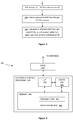
- FIG. 2 A general method according to several embodiments of the invention is shown in Figure 2 .
- This method might be implemented by a radio base station, e.g., an LTE eNodeB, or other fixed node in a wireless network, or by one or more such nodes.
- a radio base station e.g., an LTE eNodeB, or other fixed node in a wireless network, or by one or more such nodes.
- an eNodeB or other node acquires per-transmission point CSI feedback for several transmission points, from a UE of interest.
- the node performs link adaptation for a CoMP transmission, i.e., adjusting power levels and the like, based on an assumption that the signals from the several transmission points involved in the CoMP transmission will combine in a non-coherent fashion at the UE.
- the eNodeB transmits data from the multiple transmission points to the UE, according to the link adaptation calculations, but with induced frequency selectivity applied per each involved transmission point, so as to make the signals combine non-coherently at the UE.
- the frequency-selective phase shifts between the transmission point transmissions may be applied in a random or pseudo-random manner, or carefully planned (deterministically) to maximize the incoherency between transmission points. Moreover, a combination of deterministic and random or pseudo-random phase shifts may be used. In transmission modes that rely on DMRS, the transmission point-specific phase shifts can be implemented without affecting the processing in the UE, since the DMRS will experience the same phase shifts as the signal.
- the eNodeB or other node receives, at least, per-point CSI feedback from a UE.
- the eNodeB applies frequency-selective phase shifts per transmission point on signals that are part of the joint transmission.
- the granularity (in frequency) of the applied phase shifts is constrained. That is, the phase may be constrained to be static within segments of the bandwidth.
- the precoding phase shifts
- PRG resource-block group
- an artificial frequency selectivity can be induced by applying phase shifts on a per-PRG granularity.
- PRGs the size of the PRG may be one PRB.
- phase shift need not change between every adjacent PRG; applying phase shifts on a per-PRG granularity means that while phase shifts within every PRG are constant, the phase shifts vary among at least some of the PRGs.
- the transmission point-specific frequency-selective phase shift that is applied in a downlink data transmission can be expressed as a function: ⁇ PRG , TP , which associates a phase shift (in radians) to a given PRG and transmission point (TP).
- the PRGs can, for example, be indexed increasingly over the full system bandwidth (i.e., independently of the UE allocation), or increasingly within the UE allocation (i.e., only PRGs allocated to a UE are indexed).
- the applied phase shifts in frequency may be generated using random, pseudo-random, or deterministic sequences, or combinations thereof. Examples of each approach are presented in detail below.
- the eNodeB creates joint transmission hypotheses from the per-CSI-RS resource hypotheses reported by the UE. By assuming that the transmitted signals combine in an incoherent manner, the eNodeB can perform link adaptation with a high degree of accuracy as described in some of the following embodiments.
- pseudo-random TP-specific frequency-selective phase shifts are used.
- a pseudo-random sequence can be initialized using a seed that, for example, depends (but not necessarily exclusively) on the subframe index and a transmission point index.
- this sequence (mapped on to two dimensions) as RAND ( n , m ), where each index n and m results in a realization of a real valued number in the range [0,1), typically uniformly distributed within the range.
- the realizations should have some degree of "randomness" between different indices.
- Another approach involves the use of deterministic phase shifts for maximized incoherency.
- the incoherency is maximized by applying a pattern of phase shifts that ensures incoherent combination of signals from different transmission points.
- orthogonal sequences is particularly beneficial in the case when the natural phase variations between the links from the UE to strong transmission points are small. It is also beneficial if the sequences have elements of unit amplitude, since that will ensure that the orthogonality is fully induced by means of phase shifts, rather than from amplitude difference between elements.
- mod denotes the modulo operator (i.e., the remainder of the integer fraction PRG/N)
- arg(*) denotes the argument/phase (in radians) of a complex scalar.
- One particularly suitable set of sequences satisfying the above premises are Discrete Fourier Transform rotations.
- the number of PRGs that are covered by one sequence should preferably not exceed the coherence bandwidth of the channel (i.e., the bandwidth over which the channel is essentially constant). Otherwise, maximized incoherent combination cannot be guaranteed. (On the other hand, narrow coherence bandwidths will reduce the need for planned incoherency since the natural frequency selectivity of the channel then will improve the incoherent combining.)
- eNodeB implementation divides the system bandwidth into subbands of consecutive PRBs (and consecutive PRGs), which form an entity for scheduling.
- the length of the orthogonal sequence is the same as the number of PRGs in the subband, or if the subband size, in PRGs, is an integer multiple of the sequence length. This will ensure that incoherent combination from different TPs is guaranteed for each subband independently.
- the same sequence may be reused by multiple transmission points. This has the implication that incoherent combination of signals from transmission points that share the same sequence cannot be guaranteed.
- the sequences should be assigned to transmission points so that the transmission points corresponding to the weakest received signals (i.e., the TPs associated with the smallest per- CSI-RS resource CQIs) should primarily share sequences, whereas the dominating TPs should have unique sequences. This approach ensures that the vast majority of the received power at the UE is received with guaranteed incoherent combination.
- a system having a subband size of six PRBs and a PRG size of two PRBs would benefit from having a sequence length of three.
- Each of the two dominating transmitting points could then be assigned its own unique sequence, while the remaining participating transmission points share the last sequence. In this way, the signals from the two dominating transmission points will have incoherent combination each other and with all other transmission points, whereas only signals among the weakest transmission points may experience destructive coherent combination.
- a third approach utilizes both deterministic phase shifts for maximized incoherency and pseudo-random subband phase shifts.
- the two approaches discussed above which use random and planned patterns of phase shifts, respectively, are combined, to introduce a randomization between subbands of the signal combinations seen at the UE.
- This approach is particularly beneficial when there are more transmission points than a preferred sequence length, since some level of incoherence can also be induced among the transmission points that would share a sequence with the approach that uses only a limited set of orthogonal sequences.
- the second term in this expression is identical to the phase shift given earlier for the deterministic approach, where phases from a TP-specific sequence are assigned to PRGs transmitted from that transmission point.
- the first term (which includes a "floor" function) introduces a random phase from one group of PRGs (e.g., a subband) to another. This phase remains the same within each group of N PRGs.
- the random (or pseudo-random) element is derived from a TP-specific index (e.g., a transmission point identifier TP), with such a construction there will be a TP-specific random phase shift for each subband, which ensures that neighboring subbands will combine differently even for TPs that share the same sequence.
- TP-specific index e.g., a transmission point identifier TP
- the subband-specific phase shift can also be planned to induce maximum incoherence, reusing e.g., the DFT phase rotations along the same lines as discussed above.
- pairs of maximum phase shifts for the non-strongest transmission points are used.
- the eNodeB sets the phase shift to zero in the entire bandwidth for the strongest transmission point, so as to simplify the design of phase shifts for the other transmission points.
- Another advantage is that the received signal then matches the received signal from a single-point transmission if the strongest point dominates.
- the maximally separated pairs of PRGs ensure that there will be a high degree of incoherency between the strongest TP and the other TPs involved in the joint transmission.
- the randomization between the pairs of PRGs will provide a random separation between all transmission points with at least a two-PRG periodicity.
- the eNodeB can perform link adaptation and determine transmission parameters for the joint transmission with reduced uncertainty. For instance, assume the eNodeB has received multiple per-point CQI feedback reports from a UE that is a target for a joint transmission from several coordinated transmission points. Assume further that SINR values for the relevant per-point transmission hypotheses can be derived from the CQI reports (i.e., that the rank and assumptions on interference are compatible). Then, the eNodeB may approximate the effective SINR given an incoherent joint transmission from these points by the sum of the corresponding per-point SINRs.
- Stochastically modeling of the link adaptation may also be performed.
- the eNodeB has received multiple per-point CQI feedback reports from a UE that is a target for a joint transmission, and that relevant SINR values per point and PRG interval can be derived based on this feedback.
- SINR q ⁇ SIN R q ,1 e j ⁇ q ,1 + SIN R q ,2 e j ⁇ q ,2 + ... + SIN R q , N e j ⁇ q , N ⁇ 2 , where SINR q is a random variable that describes the SINR of PRG q and SINR q,i is the estimated per point SINR of PRG q on the i-th transmission point that is involved in the joint transmission.
- the UE evaluates the CQIs over multiple PRGs, for which case the estimated per point SINRs are the same over the same ranges of PRGs.
- the feedback is provided with a minimum granularity that is referred to as a subband.
- the independent and uniformly distributed random variables ⁇ q,i ⁇ [0,2 ⁇ ) correspond to the random phase shifts between incoherent signals.
- the performance will depend on the non-ordered set of SINRs per PRG corresponding to the bandwith that is allocated to the UE. Because the order of the SINRs does not have a significant impact in the link adaptation, the non-ordered distribution of the SINRs will be substantially more predictable than the per PRG distribution.
- the non-ordered distribution corresponding to a subband will be particularly predictable, especially if the phases are planned so that there for example is one PRG with constructive combining, one intermediate, and yet another PRG with destructive combining.
- the eNodeB may not be designed to handle link adaptation given random SINR values with this particular distribution. It is possible, however, to sample the distribution with an increasing number of realizations per subband until sufficiently good approximation is attained. This set of samples may then be used as regular input to the conventional link adaptation algorithm.
- Another option for improving the link adaptation is to allow the UE to report an aggregated CQI (recommended transport block size) assuming an incoherent transmission between transmission points as described above.
- this incoherent aggregated CQI which could be reported per subband or as a wideband report, provides a recommended link adaptation for the incoherent transmission. Since the assumed transmission is incoherent, the corresponding aggregate CQI will be robust to phase and frequency synchronization errors (as opposed to an aggregate CQI assuming a coherent transmission). Since the CQI assumes an incoherent transmission between transmission points, there is hence no need to feed back any inter CSI-RS resource phase feedback, which would be redundant for the recommended CQI.
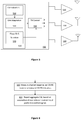
- Figure 3 is a process flow diagram illustrating generally the techniques discussed above for calculating an effective SINR for a multipoint transmission, based on the assumption that the transmissions from the different transmission points are received incoherently.
- the illustrated technique can be combined with any of the techniques described above for inducing this incoherency, of course.
- the eNodeB acquires per-transmission point CSI feedback from the UE of interest.
- the node derives a per-point SINR from the per-TP CSI feedback, using techniques that are well known.
- the node calculates an effective SINR from the per-point SINRs, based on the assumption that the signals are received incoherently at the UE. This assumption is valid, of course, if one or more of the earlier described techniques for inducing incoherency are used.
- introducing induced frequency selectivity for joint transmissions allows the eNodeB to reduce its uncertainty regarding the coherency of the joint transmission. Reduced uncertainty on how the jointly transmitted signals combine leads to reduced need for backoff in the link adaptation, which in turn leads to a higher throughput. In other words, induced randomness in the transmission actually makes the link more stable. The potential loss that results from mixing constructive and destructive combining is in many cases less significant than the gain obtained from reducing the uncertainty in the link throughput.
- a common scenario is that the propagation channel between the UE and the strongest transmission point has a low degree of frequency selectivity.
- this embodiment ensures that the transmission from the strongest point remains unaltered, so that if the strongest point dominates the received signal resembles the single point transmission.
- a base station communicates with access terminals and is referred to in various contexts as an access point, Node B, Evolved Node B (eNodeB or eNB) or some other terminology.
- Node B Evolved Node B
- eNodeB or eNB Evolved Node B
- the various base stations discussed herein are generally described and illustrated as though each base station is a single physical entity, those skilled in the art will recognize that various physical configurations are possible, including those in which the functional aspects discussed here are split between two or more physically separated units.
- some components involved in a Coordinated Multipoint Transmission such as the antennas, are necessarily distributed across several geographically diverse sites.
- base station is used herein to refer to a collection of functional elements that controls transmissions to one or more mobile terminals, even though the base station may or may not be implemented as a single physical unit.
- FIG. 4 is a block diagram illustrating some components of a base station 400, illustrating a few of the components relevant to the present techniques.
- the pictured apparatus includes radio circuitry 410 and baseband & control processing circuit 420.
- Radio circuitry 410 is connected to the antennas of two or more transmission points that may be coordinated for a transmission to a given UE, and includes receiver circuits and transmitter circuits that use known radio processing and signal processing components and techniques, typically according to a particular telecommunications standard such as the 3GPP standard for LTE and/or LTE-Advanced.
- portions of radio circuitry 410 may be distributed among several different physical units, in some embodiments, supporting corresponding distinct transmission points. Because the various details and engineering trade-offs associated with the design and implementation of such circuitry are well known and are unnecessary to a full understanding of the invention, additional details are not shown here.
- Baseband & control processing circuit 420 includes one or more microprocessors or microcontrollers 430, as well as other digital hardware 435, which may include digital signal processors (DSPs), special-purpose digital logic, and the like. Either or both of microprocessor(s) 430 and digital hardware may be configured to execute program code 442 stored in memory 440, along with radio parameters 444.
- DSPs digital signal processors
- radio parameters 444 may be configured to execute program code 442 stored in memory 440, along with radio parameters 444.
- this network interface circuit is configured for communication with other nodes in the wireless network.
- this network interface circuit is configured to communicate with other eNodeB's using the X2 interface defined by 3GPP specifications, as well as with one or more Mobility Management Entities (MMEs) using 3GPP's S1 interface.
- MMEs Mobility Management Entities
- the program code 442 stored in memory circuit 440 which may comprise one or several types of memory such as read-only memory (ROM), random-access memory, cache memory, flash memory devices, optical storage devices, etc., includes program instructions for executing one or more telecommunications and/or data communications protocols, as well as instructions for carrying out one or more of the techniques described herein, in several embodiments.
- Radio parameters 444 include various pre-determined configuration parameters as well as parameters determined from system measurements, such as channel measurements, and may include, for example, information defining CoMP clusters, orthogonal sequences or other parameters used for inducing incoherent combining of signals transmitted from different transmission points and/or different PRG groups, and the like.
- processing circuits such as the baseband & control processing circuits 420 of Figure 4 , are configured to carry out one or more of the techniques described above for inducing frequency selectivity among coordinated transmission points and/or performing link adaptation based on the resulting assumption that transmissions from the coordinated transmission points will combine incoherently at the targeted UE.
- these processing circuits are configured with appropriate program code, stored in one or more suitable memory devices, to implement one or more of the techniques described herein.
- program code stored in one or more suitable memory devices
- FIG. 5 is another block diagram, this one presenting a functional view of a fixed network node 500 according to some embodiments of the present invention.
- Fixed network node 500 which may be an eNodeB, for example, includes a processing unit 510 and a transmitter control unit 550; either or both of these functions may correspond to the baseband and control processing circuit 420 shown in Figure 4 , in some embodiments.
- Processing function 510 includes a CSI evaluation unit that is configured to acquire channel state information for each of a plurality of transmission points from a UE, as well as a link adaptation unit that is configured to determine transmission parameters for a joint transmission from the plurality of transmission points to the UE, based on an assumption of non-coherent combining of signals at the user equipment.
- Processing function 510 further includes a phase shift selection unit 540, which determines a set or sequence of phase shifts to be used to induce frequency selectivity to transmitted data signals on a per-transmission point basis. These phase shifts are provided to the transmitter control unit 550, which is configured to transmit data signals from each of the plurality of transmission points to the user equipment, using the phase shifts, so that the transmitting includes the application of an induced frequency selectivity to the transmitted data signals on a per-transmission-point basis
- fixed network node 500 is configured to carry out one or more of the techniques described above for inducing frequency selectivity among coordinated transmission points and/or performing link adaptation based on the resulting assumption that transmissions from the coordinated transmission points will combine incoherently at the targeted UE.
- one or more of the units illustrated in Figure 5 are implemented using computer processing circuits that are configured with appropriate program code, stored in one or more suitable memory devices, to implement one or more of the techniques described herein. Again, of course, it will be appreciated that not all of the steps of these techniques are necessarily performed in a single microprocessor or even in a single module.
- LTE has adopted an implicit channel state information feedback mechanism which corresponds to a CQI/PMI/RI report.
- channel information e.g., elements of a complex valued effective channel
- a reported CQI is a recommended transport block size (e.g., code rate) for an assumed transmission to the UE.
- transport block size e.g., code rate
- the CQI reporting assumes a special precoder cycling that is fully specified, whereas in transmission mode 4 the UE also recommends a RI and PMI, and the CQI reporting assumes a transmission following the RI/PMI recommendation.
- 3GPP is specifying CoMP transmissions from multiple transmission points.
- the UE and eNodeB must have a contract (standardized) that specifies the exact downlink transmission the CQI is applicable for.
- the UE recommends an aggregate CQI, assuming that the transmission is transmitted incoherently between transmission points, e.g., according to one or more of the techniques described above.
- the UE first measures a separate channel response for each of two or more reference signals or groups of reference signals. These reference signals are CSI-RS, in some cases. Each reference signal or group of reference signals will usually, but does not necessarily, correspond to a transmission point.
- the illustrated method continues, as shown at block 620, with the reporting of at least one aggregated CQI, based on the measured channel responses and based on an assumption that jointly transmitted signals corresponding to the measured channel responses will combine in a non-coherent fashion at the user equipment.
- this assumption at the UE can be combined with a procedure in which the UE recommends a separate PMI for each transmission point (more specifically, for each CSI-RS resource of the CoMP Measurement Set), and assumes for the CSI report that the jointly transmitted signal is transmitted using the per-TP PMIs, but is transmitted incoherently between transmission points.
- the aggregated CQI can be determined by the UE based on an assumption that one or more known sequences of phase shifts are to be applied to corresponding ones of the jointly transmitted signals.
- the UE may be pre-programmed with information identifying the phase shift sequences to use, for example.
- the phase shifts for the one or more known sequences of phase shifts may be based on Discrete Fourier Transform rotations, in some embodiments.
- the signals that are ultimately transmitted need not necessarily be modified in accordance with the assumed phase shifts. Nevertheless, the reported CQI reflects a shared assumption that can be used by the network to properly evaluate the meaning of the reported CQI and to determine an effective transmission scheme.
- a UE is adapted to adjust its CSI reporting procedure based on whether it can "assume” that the multiple transmission points involved in a subsequent joint transmission transmit the desired signal so that the transmissions will combine incoherently at the UE, e.g., according to one of the techniques described above. In some cases this assumption that the transmissions will be transmitted in an incoherent fashion is based on a predetermined "contract,” or shared understanding, between the UE and the eNodeB.
- This contract may be based on, for example, a standardized assumption that CSI reporting for one or more transmission modes or other operating modes for the UE should be based on incoherent transmission between TPs (more specifically effective channels of associated CSI-RSs) by the network.
- TPs more specifically effective channels of associated CSI-RSs
- explicit or implicit signaling transmitted to the UE triggers a mode wherein subsequent CSI reporting is based on the assumption of incoherent transmission.
- the eNodeB can configure (or there can be a predetermined contract) that a specific pattern of frequency selective relative phase shifts (which could be static, or fully or partially pseudo random) should be applied to the transmissions between two or more effective channels between the network and the UE.
- a specific pattern of frequency selective relative phase shifts which could be static, or fully or partially pseudo random
- some embodiments of the UE discussed above may be configured to base CQI reporting on a predetermined shared understanding that a particular pattern of frequency selective relative phase shifts are applied to transmissions from two or more transmission points for which the UE is performing CSI reporting.
- a UE according to these aspects of the invention may have a structure that is generally similar to the base station 400 illustrated in Figure 4 , with the individual components adapted in terms of size, performance, and specific operation according to well known aspects of mobile terminal design. Accordingly, while the size, weight, and specific performance requirements will vary, a UE according to the invention will generally comprise radio circuitry and baseband & control processing circuitry, where the radio circuitry is connected to one or more antennas and includes receiver circuits and transmitter circuits that use known radio processing and signal processing components and techniques, typically according to a particular telecommunications standard such as the 3GPP standard for LTE and/or LTE-Advanced. Because the various details and engineering trade-offs associated with the design and implementation of such circuitry are well known and are unnecessary to a full understanding of the invention, additional details are not shown here.
- a UE includes a baseband & control processing circuit that includes one or more microprocessors or microcontrollers, as well as other digital hardware, which may include digital signal processors (DSPs), special-purpose digital logic, and the like.
- the baseband & control processing circuit of the UE is configured to execute program code stored in memory, along with radio parameters, including program instructions for carrying out CSI reporting according to one or several of the techniques described above.
Landscapes
- Engineering & Computer Science (AREA)
- Signal Processing (AREA)
- Computer Networks & Wireless Communication (AREA)
- Mobile Radio Communication Systems (AREA)
Claims (6)
- Procédé, dans un équipement utilisateur (120), pour signaler des informations d'état de canal, le procédé comprenant :
la mesure (610) d'une réponse de canal séparée pour chacun de deux signaux de référence ou groupes de signaux de référence ou plus, chaque signal de référence ou groupe de signaux de référence correspondant à au moins un point de transmission,
dans lequel le procédé comprend en outre :le signalement (620) d'au moins un indicateur de qualité de canal, CQI, agrégé sur la base des réponses de canal séparées mesurées et sur la base d'une supposition que les signaux transmis conjointement correspondant aux réponses de canal séparées mesurées, sur une base de réponse par canal, se combinent de manière non cohérente au niveau de l'équipement utilisateur,
caractérisé en ce quele signalement de l'au moins un CQI agrégé est en outre basé sur une prédétermination qu'une combinaison de séquences aléatoires et déterministes de décalages de phase sélectifs en fréquence est appliquée aux transmissions de l'au moins un point de transmission. - Équipement utilisateur (400) conçu pour fonctionner dans un réseau sans fil, l'équipement utilisateur (400) comprenant :un circuit radio (410) conçu pour recevoir deux signaux de référence ou groupes de signaux de référence ou plus, chaque signal de référence ou groupe de signaux de référence correspondant à au moins un point de transmission, et pour transmettre des informations d'état de canal, CSI, au réseau sans fil, etun processeur de bande de base (420) conçu pour mesurer une réponse de canal séparée pour chaque signal de référence ou groupe de signaux de référence,
le processeur de bande de base (420) étant en outre conçu pour signaler au moins un indicateur de qualité de canal, CQI, agrégé à l'aide du circuit radio (410), l'au moins un CQI agrégé étant basé sur les réponses de canal séparées mesurées et étant basé sur une supposition que les signaux transmis conjointement correspondant aux réponses de canal séparées mesurées, sur une base de réponse par canal, se combinent de manière non cohérente au niveau de l'équipement utilisateur (400),
caractérisé en ce quele processeur de bande de base (420) est en outre conçu pour signaler l'au moins un CQI agrégé sur la base d'une prédétermination qu'une combinaison de séquences aléatoires et déterministes de décalages de phase sélectifs en fréquence est appliquée aux transmissions de l'au moins un point de transmission. - Équipement utilisateur (400) selon la revendication 2, dans lequel le processeur de bande de base (420) est en outre conçu pour signaler l'au moins un CQI agrégé sur une base par sous-bande pour deux sous-bandes de fréquence ou plus.
- Équipement utilisateur (400) selon la revendication 2, dans lequel le processeur de bande de base (420) est en outre conçu pour signaler l'au moins un CQI agrégé en tant que CQI agrégé unique correspondant à une bande passante de liaison entière.
- Équipement utilisateur (400) selon l'une quelconque des revendications 2 à 4, dans lequel chacun des CQI agrégés indique une taille de bloc de transport recommandée.
- Équipement utilisateur (400) selon l'une quelconque des revendications 2 à 5, dans lequel le processeur de bande de base (420) est en outre conçu pour signaler un indicateur de matrice de précodage, PMI, recommandé pour chacune des réponses de canal séparées mesurées, par l'intermédiaire du circuit radio (410), dans lequel l'au moins un CQI agrégé signalé est en outre basé sur le PMI recommandé.
Applications Claiming Priority (4)
| Application Number | Priority Date | Filing Date | Title |
|---|---|---|---|
| US201261611316P | 2012-03-15 | 2012-03-15 | |
| US201261612756P | 2012-03-19 | 2012-03-19 | |
| SE2012050609 | 2012-06-07 | ||
| PCT/SE2012/050653 WO2013137793A1 (fr) | 2012-03-15 | 2012-06-15 | Incohérence induite pour la transmission conjointe |
Publications (2)
| Publication Number | Publication Date |
|---|---|
| EP2826159A1 EP2826159A1 (fr) | 2015-01-21 |
| EP2826159B1 true EP2826159B1 (fr) | 2018-10-17 |
Family
ID=46384453
Family Applications (1)
| Application Number | Title | Priority Date | Filing Date |
|---|---|---|---|
| EP12730062.2A Active EP2826159B1 (fr) | 2012-03-15 | 2012-06-15 | Incohérence induite pour la transmission conjointe |
Country Status (3)
| Country | Link |
|---|---|
| US (1) | US9467211B2 (fr) |
| EP (1) | EP2826159B1 (fr) |
| WO (1) | WO2013137793A1 (fr) |
Families Citing this family (22)
| Publication number | Priority date | Publication date | Assignee | Title |
|---|---|---|---|---|
| US20130303230A1 (en) * | 2012-05-10 | 2013-11-14 | Samsung Electronics Co., Ltd | Method and apparatus for aggregated cqi for coordinated multipoint transmission |
| US9204317B2 (en) | 2012-05-11 | 2015-12-01 | Telefonaktiebolaget L M Ericsson (Publ) | Methods and arrangements for CSI reporting |
| KR20140045752A (ko) * | 2012-10-09 | 2014-04-17 | 삼성전자주식회사 | 빔포밍을 사용하는 무선 통신시스템의 피드백 정보 송수신 장치 및 방법 |
| WO2014123317A1 (fr) * | 2013-02-07 | 2014-08-14 | 엘지전자 주식회사 | Procédé permettant de mesurer un canal et un brouillage dans un système de communication sans fil |
| US9923621B2 (en) * | 2013-02-16 | 2018-03-20 | Cable Television Laboratories, Inc. | Multiple-input multiple-output (MIMO) communication system |
| US9578539B1 (en) * | 2013-07-19 | 2017-02-21 | Sprint Spectrum L.P. | Transmitting a data packet over a wireless communication link |
| EP3162152B1 (fr) | 2014-06-27 | 2024-10-09 | Samsung Electronics Co., Ltd. | Procédé et dispositif de transmission de données |
| EP4293972A3 (fr) | 2014-06-27 | 2024-03-27 | Samsung Electronics Co., Ltd. | Procédé et dispositif de transmission de données |
| CN106664178B (zh) | 2014-06-27 | 2020-06-02 | 泰科弗勒克斯公司 | 带宽信令 |
| CN106664277B (zh) | 2014-06-27 | 2021-09-07 | 泰科弗勒克斯公司 | 用于发送数据单元的方法和装置 |
| CN106575983B (zh) * | 2014-09-12 | 2020-08-14 | 华为技术有限公司 | 用于在无线通信系统中转换控制区域的方法及装置 |
| US9544032B2 (en) * | 2014-11-20 | 2017-01-10 | Huawei Technologies Canada Co., Ltd. | System and method for multiple-input multiple-output (MIMO) orthogonal frequency division multiplexing (OFDM) offset quadrature amplitude modulation (OQAM) |
| US9705635B2 (en) | 2015-03-06 | 2017-07-11 | At&T Intellectual Property I, L.P. | Apparatus and method to identify user equipment performance and to optimize network performance via big data |
| US10320538B2 (en) * | 2015-03-23 | 2019-06-11 | Deutsche Telekom Ag | Method and system for coordinated radio resource assignment |
| CN108141265B (zh) * | 2015-10-12 | 2021-12-07 | 瑞典爱立信有限公司 | 确定无线通信网络中的信道状态测量的无线设备、网络节点及其中的方法 |
| US10673652B2 (en) * | 2017-03-02 | 2020-06-02 | Futurewei Technologies, Inc. | System and method for providing explicit feedback in the uplink |
| KR102521791B1 (ko) * | 2017-06-14 | 2023-04-13 | 엘지전자 주식회사 | 무선 통신 시스템에서 채널 상태 정보를 보고하는 방법 및 이를 위한 장치 |
| KR102420040B1 (ko) * | 2017-12-05 | 2022-07-13 | 삼성전자주식회사 | 협력 전송을 통해 복수의 ap와 데이터 통신을 수행할 수 있는 전자 장치 및 이의 제어 방법 |
| CN109379748B (zh) * | 2018-12-29 | 2021-10-26 | 京信网络系统股份有限公司 | 信号收发单元的小区划分方法、装置及计算机设备 |
| CN111294090B (zh) * | 2019-07-24 | 2023-02-28 | 展讯通信(上海)有限公司 | 多ap操作的反向触发系统以及接入点 |
| CN114747158A (zh) * | 2019-12-13 | 2022-07-12 | 瑞典爱立信有限公司 | 用于共享无线电系统的辅助天线校准 |
| WO2023235079A1 (fr) * | 2022-05-30 | 2023-12-07 | Intel Corporation | Réduction de puissance de crête à moyenne dans une radio à entrées multiples et sorties multiples (mimo) |
Family Cites Families (7)
| Publication number | Priority date | Publication date | Assignee | Title |
|---|---|---|---|---|
| KR20100138263A (ko) * | 2009-06-24 | 2010-12-31 | 주식회사 팬택 | 적응형 순환 지연 다이버서티를 이용한 다중 포인트 협력형송수신 방법 및 그를 이용한 시스템측 장치와 수신장치, 협력형 기지국 세트 결정 방법 |
| CN103299558B (zh) * | 2011-01-07 | 2016-07-06 | 交互数字专利控股公司 | 无线发射/接收单元和由无线发射/接收单元执行的方法 |
| US8675558B2 (en) * | 2011-01-07 | 2014-03-18 | Intel Corporation | CQI definition for transmission mode 9 in LTE-advanced |
| US9131405B2 (en) * | 2011-01-31 | 2015-09-08 | Lg Electronics Inc. | Method of transmitting and receiving channel status information on multi-cell operation in a wireless communication system and apparatus for the same |
| US8638867B2 (en) * | 2011-04-27 | 2014-01-28 | Broadcom Corporation | Methods and apparatus for compensating for propagation delays in coordinated multi-point transmission |
| US9735844B2 (en) * | 2011-05-09 | 2017-08-15 | Texas Instruments Incorporated | Channel feedback for coordinated multi-point transmissions |
| WO2013070577A1 (fr) * | 2011-11-07 | 2013-05-16 | Motorola Mobility Llc | Procédé et appareil de renvoi de données d'état de canal (csi) pour schémas combinés de traitement dans un système de communication à multiplexage par répartition orthogonale en fréquence avec transmission multipoint coordonnée |
-
2012
- 2012-06-15 US US13/577,467 patent/US9467211B2/en not_active Expired - Fee Related
- 2012-06-15 WO PCT/SE2012/050653 patent/WO2013137793A1/fr not_active Ceased
- 2012-06-15 EP EP12730062.2A patent/EP2826159B1/fr active Active
Non-Patent Citations (1)
| Title |
|---|
| None * |
Also Published As
| Publication number | Publication date |
|---|---|
| US20130242769A1 (en) | 2013-09-19 |
| US9467211B2 (en) | 2016-10-11 |
| WO2013137793A1 (fr) | 2013-09-19 |
| EP2826159A1 (fr) | 2015-01-21 |
Similar Documents
| Publication | Publication Date | Title |
|---|---|---|
| EP2826159B1 (fr) | Incohérence induite pour la transmission conjointe | |
| CN110832803B (zh) | 用于多用户多入多出的干扰测量和信道状态信息反馈 | |
| US9401748B2 (en) | Method and apparatus for channel state information feedback in a coordinated multi-point communication system | |
| KR102323003B1 (ko) | 이동통신시스템에서 간섭 측정 방법 및 장치 | |
| CN106797649B (zh) | 与灵活的csi配置和关联反馈有关的系统和方法 | |
| US11350291B2 (en) | Beam tracking mobile communication system, base station, and user equipment | |
| JP7158490B2 (ja) | 複数の仮定を伴うチャネル状態情報(csi)フィードバック | |
| RU2629944C2 (ru) | Способы и конструкции для передачи отчетов с csi | |
| JP6495187B2 (ja) | モバイル通信システムで複数のアンテナを用いてフィードバック情報を送受信するための方法及び装置 | |
| US9660784B2 (en) | Method and apparatus providing inter-transmission point phase relationship feedback for joint transmission CoMP | |
| CN102415003B (zh) | 信道状态信息的高效上行链路传送 | |
| US10014976B2 (en) | Method and apparatus for measuring MU-MIMO interference in mobile communication system | |
| KR20200116444A (ko) | 무선 통신 시스템에서 채널 상태 정보 송수신 방법 및 장치 | |
| US8478203B2 (en) | Phase synchronization of base stations via mobile feedback in multipoint broadcasting | |
| US11811484B2 (en) | Apparatuses and methods for multi-user transmissions | |
| CN103326761B (zh) | 信道状态信息处理方法及装置 | |
| KR20140142297A (ko) | 채널상태보고를 위한 조정된 다지점 전송 추정의 구성 | |
| US20130250876A1 (en) | Method And Apparatus Providing Inter-Transmission Point Phase Relationship Feedback For Joint Transmission CoMP | |
| US20140286267A1 (en) | Efficient uplink transmission of channel state information | |
| US10594378B2 (en) | Wireless device, a network node and methods therein for determining channel state measurements in a wireless communications network | |
| CN108141307B (zh) | 用于共享干扰信息的控制实体、接入节点和方法 | |
| CN106664128B (zh) | 信道状态信息的有效上行链路传送 | |
| CN107733618A (zh) | 测量导频的发送方法、信道状态信息的反馈方法及装置 |
Legal Events
| Date | Code | Title | Description |
|---|---|---|---|
| PUAI | Public reference made under article 153(3) epc to a published international application that has entered the european phase |
Free format text: ORIGINAL CODE: 0009012 |
|
| 17P | Request for examination filed |
Effective date: 20140623 |
|
| AK | Designated contracting states |
Kind code of ref document: A1 Designated state(s): AL AT BE BG CH CY CZ DE DK EE ES FI FR GB GR HR HU IE IS IT LI LT LU LV MC MK MT NL NO PL PT RO RS SE SI SK SM TR |
|
| AX | Request for extension of the european patent |
Extension state: BA ME |
|
| DAX | Request for extension of the european patent (deleted) | ||
| 17Q | First examination report despatched |
Effective date: 20160817 |
|
| STAA | Information on the status of an ep patent application or granted ep patent |
Free format text: STATUS: EXAMINATION IS IN PROGRESS |
|
| REG | Reference to a national code |
Ref country code: DE Ref legal event code: R079 Ref document number: 602012052297 Country of ref document: DE Free format text: PREVIOUS MAIN CLASS: H04B0007020000 Ipc: H04B0007024000 |
|
| GRAP | Despatch of communication of intention to grant a patent |
Free format text: ORIGINAL CODE: EPIDOSNIGR1 |
|
| STAA | Information on the status of an ep patent application or granted ep patent |
Free format text: STATUS: GRANT OF PATENT IS INTENDED |
|
| RIC1 | Information provided on ipc code assigned before grant |
Ipc: H04B 7/06 20060101ALI20180627BHEP Ipc: H04B 7/024 20170101AFI20180627BHEP |
|
| INTG | Intention to grant announced |
Effective date: 20180718 |
|
| GRAS | Grant fee paid |
Free format text: ORIGINAL CODE: EPIDOSNIGR3 |
|
| GRAA | (expected) grant |
Free format text: ORIGINAL CODE: 0009210 |
|
| STAA | Information on the status of an ep patent application or granted ep patent |
Free format text: STATUS: THE PATENT HAS BEEN GRANTED |
|
| AK | Designated contracting states |
Kind code of ref document: B1 Designated state(s): AL AT BE BG CH CY CZ DE DK EE ES FI FR GB GR HR HU IE IS IT LI LT LU LV MC MK MT NL NO PL PT RO RS SE SI SK SM TR |
|
| REG | Reference to a national code |
Ref country code: GB Ref legal event code: FG4D |
|
| REG | Reference to a national code |
Ref country code: CH Ref legal event code: EP |
|
| REG | Reference to a national code |
Ref country code: IE Ref legal event code: FG4D |
|
| REG | Reference to a national code |
Ref country code: DE Ref legal event code: R096 Ref document number: 602012052297 Country of ref document: DE Ref country code: AT Ref legal event code: REF Ref document number: 1055218 Country of ref document: AT Kind code of ref document: T Effective date: 20181115 |
|
| REG | Reference to a national code |
Ref country code: NL Ref legal event code: FP |
|
| REG | Reference to a national code |
Ref country code: LT Ref legal event code: MG4D |
|
| REG | Reference to a national code |
Ref country code: AT Ref legal event code: MK05 Ref document number: 1055218 Country of ref document: AT Kind code of ref document: T Effective date: 20181017 |
|
| PG25 | Lapsed in a contracting state [announced via postgrant information from national office to epo] |
Ref country code: ES Free format text: LAPSE BECAUSE OF FAILURE TO SUBMIT A TRANSLATION OF THE DESCRIPTION OR TO PAY THE FEE WITHIN THE PRESCRIBED TIME-LIMIT Effective date: 20181017 Ref country code: HR Free format text: LAPSE BECAUSE OF FAILURE TO SUBMIT A TRANSLATION OF THE DESCRIPTION OR TO PAY THE FEE WITHIN THE PRESCRIBED TIME-LIMIT Effective date: 20181017 Ref country code: PL Free format text: LAPSE BECAUSE OF FAILURE TO SUBMIT A TRANSLATION OF THE DESCRIPTION OR TO PAY THE FEE WITHIN THE PRESCRIBED TIME-LIMIT Effective date: 20181017 Ref country code: LV Free format text: LAPSE BECAUSE OF FAILURE TO SUBMIT A TRANSLATION OF THE DESCRIPTION OR TO PAY THE FEE WITHIN THE PRESCRIBED TIME-LIMIT Effective date: 20181017 Ref country code: FI Free format text: LAPSE BECAUSE OF FAILURE TO SUBMIT A TRANSLATION OF THE DESCRIPTION OR TO PAY THE FEE WITHIN THE PRESCRIBED TIME-LIMIT Effective date: 20181017 Ref country code: IS Free format text: LAPSE BECAUSE OF FAILURE TO SUBMIT A TRANSLATION OF THE DESCRIPTION OR TO PAY THE FEE WITHIN THE PRESCRIBED TIME-LIMIT Effective date: 20190217 Ref country code: BG Free format text: LAPSE BECAUSE OF FAILURE TO SUBMIT A TRANSLATION OF THE DESCRIPTION OR TO PAY THE FEE WITHIN THE PRESCRIBED TIME-LIMIT Effective date: 20190117 Ref country code: LT Free format text: LAPSE BECAUSE OF FAILURE TO SUBMIT A TRANSLATION OF THE DESCRIPTION OR TO PAY THE FEE WITHIN THE PRESCRIBED TIME-LIMIT Effective date: 20181017 Ref country code: NO Free format text: LAPSE BECAUSE OF FAILURE TO SUBMIT A TRANSLATION OF THE DESCRIPTION OR TO PAY THE FEE WITHIN THE PRESCRIBED TIME-LIMIT Effective date: 20190117 Ref country code: AT Free format text: LAPSE BECAUSE OF FAILURE TO SUBMIT A TRANSLATION OF THE DESCRIPTION OR TO PAY THE FEE WITHIN THE PRESCRIBED TIME-LIMIT Effective date: 20181017 |
|
| PG25 | Lapsed in a contracting state [announced via postgrant information from national office to epo] |
Ref country code: RS Free format text: LAPSE BECAUSE OF FAILURE TO SUBMIT A TRANSLATION OF THE DESCRIPTION OR TO PAY THE FEE WITHIN THE PRESCRIBED TIME-LIMIT Effective date: 20181017 Ref country code: GR Free format text: LAPSE BECAUSE OF FAILURE TO SUBMIT A TRANSLATION OF THE DESCRIPTION OR TO PAY THE FEE WITHIN THE PRESCRIBED TIME-LIMIT Effective date: 20190118 Ref country code: PT Free format text: LAPSE BECAUSE OF FAILURE TO SUBMIT A TRANSLATION OF THE DESCRIPTION OR TO PAY THE FEE WITHIN THE PRESCRIBED TIME-LIMIT Effective date: 20190217 Ref country code: AL Free format text: LAPSE BECAUSE OF FAILURE TO SUBMIT A TRANSLATION OF THE DESCRIPTION OR TO PAY THE FEE WITHIN THE PRESCRIBED TIME-LIMIT Effective date: 20181017 Ref country code: SE Free format text: LAPSE BECAUSE OF FAILURE TO SUBMIT A TRANSLATION OF THE DESCRIPTION OR TO PAY THE FEE WITHIN THE PRESCRIBED TIME-LIMIT Effective date: 20181017 |
|
| REG | Reference to a national code |
Ref country code: DE Ref legal event code: R097 Ref document number: 602012052297 Country of ref document: DE |
|
| PG25 | Lapsed in a contracting state [announced via postgrant information from national office to epo] |
Ref country code: DK Free format text: LAPSE BECAUSE OF FAILURE TO SUBMIT A TRANSLATION OF THE DESCRIPTION OR TO PAY THE FEE WITHIN THE PRESCRIBED TIME-LIMIT Effective date: 20181017 Ref country code: IT Free format text: LAPSE BECAUSE OF FAILURE TO SUBMIT A TRANSLATION OF THE DESCRIPTION OR TO PAY THE FEE WITHIN THE PRESCRIBED TIME-LIMIT Effective date: 20181017 Ref country code: CZ Free format text: LAPSE BECAUSE OF FAILURE TO SUBMIT A TRANSLATION OF THE DESCRIPTION OR TO PAY THE FEE WITHIN THE PRESCRIBED TIME-LIMIT Effective date: 20181017 |
|
| PLBE | No opposition filed within time limit |
Free format text: ORIGINAL CODE: 0009261 |
|
| STAA | Information on the status of an ep patent application or granted ep patent |
Free format text: STATUS: NO OPPOSITION FILED WITHIN TIME LIMIT |
|
| PG25 | Lapsed in a contracting state [announced via postgrant information from national office to epo] |
Ref country code: RO Free format text: LAPSE BECAUSE OF FAILURE TO SUBMIT A TRANSLATION OF THE DESCRIPTION OR TO PAY THE FEE WITHIN THE PRESCRIBED TIME-LIMIT Effective date: 20181017 Ref country code: SK Free format text: LAPSE BECAUSE OF FAILURE TO SUBMIT A TRANSLATION OF THE DESCRIPTION OR TO PAY THE FEE WITHIN THE PRESCRIBED TIME-LIMIT Effective date: 20181017 Ref country code: SM Free format text: LAPSE BECAUSE OF FAILURE TO SUBMIT A TRANSLATION OF THE DESCRIPTION OR TO PAY THE FEE WITHIN THE PRESCRIBED TIME-LIMIT Effective date: 20181017 Ref country code: EE Free format text: LAPSE BECAUSE OF FAILURE TO SUBMIT A TRANSLATION OF THE DESCRIPTION OR TO PAY THE FEE WITHIN THE PRESCRIBED TIME-LIMIT Effective date: 20181017 |
|
| 26N | No opposition filed |
Effective date: 20190718 |
|
| PG25 | Lapsed in a contracting state [announced via postgrant information from national office to epo] |
Ref country code: SI Free format text: LAPSE BECAUSE OF FAILURE TO SUBMIT A TRANSLATION OF THE DESCRIPTION OR TO PAY THE FEE WITHIN THE PRESCRIBED TIME-LIMIT Effective date: 20181017 |
|
| PGFP | Annual fee paid to national office [announced via postgrant information from national office to epo] |
Ref country code: DE Payment date: 20190830 Year of fee payment: 8 |
|
| PG25 | Lapsed in a contracting state [announced via postgrant information from national office to epo] |
Ref country code: MC Free format text: LAPSE BECAUSE OF FAILURE TO SUBMIT A TRANSLATION OF THE DESCRIPTION OR TO PAY THE FEE WITHIN THE PRESCRIBED TIME-LIMIT Effective date: 20181017 |
|
| REG | Reference to a national code |
Ref country code: CH Ref legal event code: PL |
|
| REG | Reference to a national code |
Ref country code: BE Ref legal event code: MM Effective date: 20190630 |
|
| PG25 | Lapsed in a contracting state [announced via postgrant information from national office to epo] |
Ref country code: TR Free format text: LAPSE BECAUSE OF FAILURE TO SUBMIT A TRANSLATION OF THE DESCRIPTION OR TO PAY THE FEE WITHIN THE PRESCRIBED TIME-LIMIT Effective date: 20181017 |
|
| PG25 | Lapsed in a contracting state [announced via postgrant information from national office to epo] |
Ref country code: IE Free format text: LAPSE BECAUSE OF NON-PAYMENT OF DUE FEES Effective date: 20190615 |
|
| PG25 | Lapsed in a contracting state [announced via postgrant information from national office to epo] |
Ref country code: CH Free format text: LAPSE BECAUSE OF NON-PAYMENT OF DUE FEES Effective date: 20190630 Ref country code: LU Free format text: LAPSE BECAUSE OF NON-PAYMENT OF DUE FEES Effective date: 20190615 Ref country code: BE Free format text: LAPSE BECAUSE OF NON-PAYMENT OF DUE FEES Effective date: 20190630 Ref country code: LI Free format text: LAPSE BECAUSE OF NON-PAYMENT OF DUE FEES Effective date: 20190630 |
|
| PG25 | Lapsed in a contracting state [announced via postgrant information from national office to epo] |
Ref country code: FR Free format text: LAPSE BECAUSE OF NON-PAYMENT OF DUE FEES Effective date: 20190630 |
|
| REG | Reference to a national code |
Ref country code: DE Ref legal event code: R119 Ref document number: 602012052297 Country of ref document: DE |
|
| PG25 | Lapsed in a contracting state [announced via postgrant information from national office to epo] |
Ref country code: DE Free format text: LAPSE BECAUSE OF NON-PAYMENT OF DUE FEES Effective date: 20210101 Ref country code: CY Free format text: LAPSE BECAUSE OF FAILURE TO SUBMIT A TRANSLATION OF THE DESCRIPTION OR TO PAY THE FEE WITHIN THE PRESCRIBED TIME-LIMIT Effective date: 20181017 |
|
| PG25 | Lapsed in a contracting state [announced via postgrant information from national office to epo] |
Ref country code: MT Free format text: LAPSE BECAUSE OF FAILURE TO SUBMIT A TRANSLATION OF THE DESCRIPTION OR TO PAY THE FEE WITHIN THE PRESCRIBED TIME-LIMIT Effective date: 20181017 Ref country code: HU Free format text: LAPSE BECAUSE OF FAILURE TO SUBMIT A TRANSLATION OF THE DESCRIPTION OR TO PAY THE FEE WITHIN THE PRESCRIBED TIME-LIMIT; INVALID AB INITIO Effective date: 20120615 |
|
| PG25 | Lapsed in a contracting state [announced via postgrant information from national office to epo] |
Ref country code: MK Free format text: LAPSE BECAUSE OF FAILURE TO SUBMIT A TRANSLATION OF THE DESCRIPTION OR TO PAY THE FEE WITHIN THE PRESCRIBED TIME-LIMIT Effective date: 20181017 |
|
| PGFP | Annual fee paid to national office [announced via postgrant information from national office to epo] |
Ref country code: NL Payment date: 20220626 Year of fee payment: 11 |
|
| REG | Reference to a national code |
Ref country code: NL Ref legal event code: MM Effective date: 20230701 |
|
| PG25 | Lapsed in a contracting state [announced via postgrant information from national office to epo] |
Ref country code: NL Free format text: LAPSE BECAUSE OF NON-PAYMENT OF DUE FEES Effective date: 20230701 |
|
| PGFP | Annual fee paid to national office [announced via postgrant information from national office to epo] |
Ref country code: GB Payment date: 20250627 Year of fee payment: 14 |