EP2826410A1 - Staubsauger - Google Patents
Staubsauger Download PDFInfo
- Publication number
- EP2826410A1 EP2826410A1 EP14176453.0A EP14176453A EP2826410A1 EP 2826410 A1 EP2826410 A1 EP 2826410A1 EP 14176453 A EP14176453 A EP 14176453A EP 2826410 A1 EP2826410 A1 EP 2826410A1
- Authority
- EP
- European Patent Office
- Prior art keywords
- rotatable cover
- support
- hinge
- vacuum cleaner
- state
- Prior art date
- Legal status (The legal status is an assumption and is not a legal conclusion. Google has not performed a legal analysis and makes no representation as to the accuracy of the status listed.)
- Granted
Links
- 239000000428 dust Substances 0.000 claims abstract description 124
- 238000012423 maintenance Methods 0.000 claims abstract description 55
- 230000007246 mechanism Effects 0.000 claims description 53
- 230000005540 biological transmission Effects 0.000 claims description 47
- 230000006835 compression Effects 0.000 claims description 20
- 238000007906 compression Methods 0.000 claims description 20
- 238000000926 separation method Methods 0.000 description 37
- 230000004308 accommodation Effects 0.000 description 29
- 230000008878 coupling Effects 0.000 description 22
- 238000010168 coupling process Methods 0.000 description 22
- 238000005859 coupling reaction Methods 0.000 description 22
- 238000007599 discharging Methods 0.000 description 3
- 239000000463 material Substances 0.000 description 3
- 238000012986 modification Methods 0.000 description 3
- 230000004048 modification Effects 0.000 description 3
- 230000002452 interceptive effect Effects 0.000 description 2
- 238000000034 method Methods 0.000 description 2
- 230000002265 prevention Effects 0.000 description 2
- 230000000903 blocking effect Effects 0.000 description 1
- 230000000694 effects Effects 0.000 description 1
- 238000005516 engineering process Methods 0.000 description 1
- 239000000126 substance Substances 0.000 description 1
Images






Classifications
-
- A—HUMAN NECESSITIES
- A47—FURNITURE; DOMESTIC ARTICLES OR APPLIANCES; COFFEE MILLS; SPICE MILLS; SUCTION CLEANERS IN GENERAL
- A47L—DOMESTIC WASHING OR CLEANING; SUCTION CLEANERS IN GENERAL
- A47L9/00—Details or accessories of suction cleaners, e.g. mechanical means for controlling the suction or for effecting pulsating action; Storing devices specially adapted to suction cleaners or parts thereof; Carrying-vehicles specially adapted for suction cleaners
- A47L9/10—Filters; Dust separators; Dust removal; Automatic exchange of filters
- A47L9/16—Arrangement or disposition of cyclones or other devices with centrifugal action
-
- A—HUMAN NECESSITIES
- A47—FURNITURE; DOMESTIC ARTICLES OR APPLIANCES; COFFEE MILLS; SPICE MILLS; SUCTION CLEANERS IN GENERAL
- A47L—DOMESTIC WASHING OR CLEANING; SUCTION CLEANERS IN GENERAL
- A47L9/00—Details or accessories of suction cleaners, e.g. mechanical means for controlling the suction or for effecting pulsating action; Storing devices specially adapted to suction cleaners or parts thereof; Carrying-vehicles specially adapted for suction cleaners
-
- A—HUMAN NECESSITIES
- A47—FURNITURE; DOMESTIC ARTICLES OR APPLIANCES; COFFEE MILLS; SPICE MILLS; SUCTION CLEANERS IN GENERAL
- A47L—DOMESTIC WASHING OR CLEANING; SUCTION CLEANERS IN GENERAL
- A47L9/00—Details or accessories of suction cleaners, e.g. mechanical means for controlling the suction or for effecting pulsating action; Storing devices specially adapted to suction cleaners or parts thereof; Carrying-vehicles specially adapted for suction cleaners
- A47L9/10—Filters; Dust separators; Dust removal; Automatic exchange of filters
- A47L9/16—Arrangement or disposition of cyclones or other devices with centrifugal action
- A47L9/1683—Dust collecting chambers; Dust collecting receptacles
-
- A—HUMAN NECESSITIES
- A47—FURNITURE; DOMESTIC ARTICLES OR APPLIANCES; COFFEE MILLS; SPICE MILLS; SUCTION CLEANERS IN GENERAL
- A47L—DOMESTIC WASHING OR CLEANING; SUCTION CLEANERS IN GENERAL
- A47L9/00—Details or accessories of suction cleaners, e.g. mechanical means for controlling the suction or for effecting pulsating action; Storing devices specially adapted to suction cleaners or parts thereof; Carrying-vehicles specially adapted for suction cleaners
- A47L9/10—Filters; Dust separators; Dust removal; Automatic exchange of filters
- A47L9/16—Arrangement or disposition of cyclones or other devices with centrifugal action
- A47L9/1691—Mounting or coupling means for cyclonic chamber or dust receptacles
Definitions
- vacuum cleaners are appliances that suction air and dusts by using a suction force generated by a suction motor to separate the air from the dusts, thereby storing the dusts in a dust container and discharging the air to the outside.
- a technology in which a cover member is maintained in a state where the cover member is partially opened is disclosed in Korean Patent Publication No. 2010-0018785 that is a prior art document.
- the cover member when an external force is applied to the cover member, the cover member may not be maintained in the opened state, but be closed by its self-weight.
- Embodiments provide a vacuum cleaner.
- a vacuum cleaner includes: a cleaner body including a mount part; a dust container separably mounted on the mount part; a rotatable cover covering the dust container mounted on the mount part, the rotatable cover being rotatably connected to the cleaner body; and an opening maintenance unit rotating the rotatable cover up to an automatic rotation position to maintain the rotating state of the rotatable cover at the automatic rotation position.
- the rotatable cover may include a hinge mechanism
- the opening maintenance unit may include a first opening maintenance part supporting the hinge mechanism in the state where the rotatable cover rotates to the automatic rotation position.
- the first opening maintenance part may include an elastic member elastically supporting the hinge mechanism.
- the first opening maintenance part may further include a first support part supporting one end of the elastic member and a second support part supporting the other end of the elastic member, and the hinge mechanism may contact the elastic member by a hole defined by the first support part.
- the hinge mechanism may include a hinge body, a hinge shaft extending from the hinge body, and a contact part coupled to or integrated with the hinge body, and the elastic member may support the contact part in the state where the rotatable cover rotates to the automatic rotation position.
- the hinge mechanism may pass through the hole to press the elastic member, and the elastic member may be spaced apart from the first support part in a state where the rotatable cover is closed, and the elastic member may contact the first support part, and the contact part may contact one end of the elastic member on the hole in the state where the rotatable cover rotates to the automatic rotation position.
- the opening maintenance unit may include a hinge guide including the first opening maintenance part, and a guide groove for guiding movement of the hinge mechanism when the rotatable cover rotates may be defined in the hinge guide.
- the opening maintenance unit may further include a shaft support part supporting the hinge shaft.
- the opening maintenance unit may further include a second opening maintenance part supporting a lower portion of the hinge body in a state where the rotatable cover rotates from the automatic rotation position to a manual rotation position.
- the second opening maintenance part may include a support rib and a support protrusion protruding from the support rib to support the hinge body in the state where the rotatable cover rotates.
- the support protrusion may be disposed on a moving path of the hinge body while the rotatable cover rotates, the hinge body and the support protrusion may interfere with each other while the rotatable cover rotates to elastically deform at least one of the hinge body and the support rib, thereby releasing the interference between the hinge body and the support protrusion to allow the rotatable cover to further rotate, and when the rotatable cover further rotates, the hinge body may be supported by the support protrusion.
- the dust container may include a compression member for pressing dusts
- the rotatable cover may include a driving unit for driving the compression member provided in the dust container.
- the driving unit may include a compression motor and a power transmission part for transmitting a power of the compression motor into the compression member.
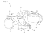
- Fig. 1 is a view of a state in which a dust container is separated from a vacuum cleaner according to an embodiment
- Fig. 2 is a cross-sectional view of a cleaner body according to an embodiment.
- a vacuum cleaner 1 may include a cleaner body 10 including a suction motor for generating a suction force therein, a dust separation mechanism mounted on the cleaner body 10 to separate dusts from suctioned air, and a dust container 30 for storing the dusts separated from the dust separation mechanism 20.
- the vacuum cleaner 1 may further include a connection hose, a suction tube, and a suction nozzle.
- the cleaner body 10 may include a plurality of main wheels 11 and auxiliary wheels 12 for moving.
- the cleanser body 10 may include a main body inflow part through which the air suctioned through the suction nozzle is introduced.
- the air introduced into the cleaner body 10 through the main body inflow part 14 may be introduced into the dust separation mechanism 20.
- the air introduced into the cleaner body 10 may be introduced into the dust separation mechanism 20 through a lower side of the dust separation mechanism 20.
- the cleaner body 10 may include a mount part 13 on which the dust separation mechanism 20 and the dust collection 30 are mounted.
- the mount part 13 may be disposed on a front side of the cleaner body 10, but is not limited thereto.
- the dust separation mechanism 20 is mounted first on the mount part 12, and the dust container 30 may be mounted.
- the dust container 30 may communicate with the dust separation mechanism 20.
- the cleaner body 10 may further include a rotatable cover 15 covering the dust separation mechanism 20 and the dust container 30 in the state where the dust separation mechanism 20 and the dust container 30 are mounted on the mount part 13.
- the rotatable cover 15 may be rotatably connected to an upper portion of the cleaner body 10.
- the rotatable cover 15 may cover an upper side of each of the dust separation mechanism 20 and the dust container 30.
- the dust container 30 In the dust container 30 is mounted on the mount part 13, the dust container 30 may surround a portion of a circumference of the dust separation mechanism 20. Thus, when the rotatable cover 15 covers the dust separation mechanism 20 and the dust container 30 after the dust separation mechanism 20 is mounted on the mount part 13, and then the dust container 30 is mounted on the mount part 13, the dust separation mechanism 20 may not be exposed to the outside of the cleaner body 10.
- the dust separation mechanism 20 since the dust separation mechanism 20 is covered by the dust container 30 and the rotatable cover 15, the dust separation mechanism 20 may be fixed in position without a separate fixing unit for fixing the dust separation mechanism 20 to the cleaner body 10. That is, the dust container 30 and the rotatable cover 15 may prevent the dust separation mechanism 20 from moving.
- the rotatable cover 15 may be coupled to the dust container 30 in the state where the rotatable cover 15 covers the dust container 30.
- the rotatable cover 15 may be coupled to the cleaner body 10 in the state where the rotatable cover 15 covers the dust container 30.
- the dust container 30 may be coupled to the cleaner body 10 to fix the position of the dust container 30.
- the dust separation mechanism 20 may separate air from the dusts by using a cyclone flow of the air, but the present disclosure is not limited thereto.
- the dust separation mechanism 20 may include a dust separation body 210 and a cover covering a side of the dust separation body 210.
- An air suction hole 212 for suctioning air and an air discharge hole 213 for discharging air may be defined in a lower side of the dust separation body 20 with respect to Fig. 2 .
- a filter 214 for allowing air to pass and blocking a dust having a predetermined size or more may be coupled to a bottom of the dust separation body 210.
- the air suctioned through the air suction hole 212 may pass through the filter 214 and then be discharged from the dust separation body 210 through the air discharge hole 213.
- a dust discharge hole 216 for discharging dusts separated from the air may be defined in a side surface of the dust separation body 210.
- the dust discharge hole 216 may be defined at a position higher than those of the air suction hole 212 and the air discharge hole 213.
- Fig. 3 is a perspective cross-sectional view of the dust collection according to an embodiment
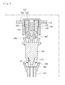
- Fig. 4 is a cross-sectional view of a state in which a second transfer part, a connection part, and a pressing member are aligned with each other according to an embodiment.
- the dust container 30 may include a dust collection body 310 and a dust container cover covering the dust collection body 310.
- the dust collection body 310 may have an opened upper side, and the dust container cover 320 may cover the upper side of the dust collection body 310.
- a portion of the dust collection body 310 may have the same shape as that of the dust separation mechanism 20 so that the dust container 30 covers the dust separation mechanism 20.
- the dust collection body 310 may have a recess part 311 in which the dust separation mechanism 20 is disposed.
- the dust collection body 310 may include a dust inflow hole through which the dusts discharged from the dust discharge hole 216 of the dust separation mechanism 20 are introduced.
- a pressing member 360 for pressing the stored dusts may be disposed in the dust collection body 310.
- the pressing member 360 may be rotatably installed within the dust collection body 310.
- the pressing member 360 may include a rotatable shaft 364 and a pressing plate 362 extending laterally from the rotatable shaft 364.
- a fixed shaft 372 connected to the rotatable shaft 364 may be disposed on the dust collection body 310.
- the fixed shaft 372 may be disposed on a bottom of the duct collection body 310, but the present disclosure is not limited thereto.
- the fixed shaft 372 may be inserted into a lower portion of the rotatable shaft 364.
- the rotatable shaft 364 may be inserted into an upper portion of the fixed shaft 372.
- the dust collection body 310 may have a non-circular shape in horizontal cross-section. Also, while the pressing member 360 rotates, the pressing member 360 may contact an inner surface of the dust collection body 310. In the current embodiment, the pressing member 360 may contact at least two portions (hereinafter, referred to as contact parts) of the inner surface of the dust collection body 310. Thus, the pressing member 360 may rotate within a range of an angle defined by the two contact parts with respect to the rotatable shaft 364.
- the rotatable cover 15 may include a driving unit 400 generating a power for rotating the pressing member 360.
- the driving unit 400 may rotate together with the rotatable cover 15.
- the driving unit 400 may be connected to the pressing member 360 disposed within the dust container 30.
- the driving unit 400 may include a compression motor 410 that is capable of bidirectionally rotating and a power transmission part for transmitting a power of the compression motor 410.
- the power transmission part may include a first transmission part 420 connected to a shaft of the compression motor 410 and a second transmission part 430 connected to the first transmission part 420.
- the dust container cover 320 may include a connection part 450 for transmitting the power of the driving unit 400 into the pressing member 360.
- the connection part 450 may be selectively connected to the second transmission part 430 and the pressing member 360. That is, the connection part 450 may serve as a third transmission part.
- connection part 450 may be connected to the pressing member 360 (e.g., the rotatable shaft).
- the connection between the connection part 450 and the pressing member 360 may be released.
- the second transmission part 430 may be connected to the connection part 450.
- the connection between the second transmission part 430 and the connection part 450 may be released.
- a portion (e.g., the second transmission part) of the driving unit 400 may protrude outward from the rotatable cover 15, and the connection part 450 may be exposed to the outside of the dust container 30 (e.g., the dust container cover) so that the driving unit 400 (e.g., the second transmission part) is connected to the connection part 450.
- the first transmission part 420 may be, for example, a gear.
- the second transmission part 430 may include a body 432 and a plurality of gears 434 disposed along a circumference of the body 432. That is, the second transmission part 430 may serve as a gear.
- the body 434 may have an opened side having a cylindrical shape.
- An accommodation part 436 for accommodating a connection guide 440 may be disposed in the body 434.
- An elastic member 438 for proving an elastic force into the connection guide 440 may be disposed on the body 434.
- the elastic member 438 may elastically support the connection guide 440 so that the connection guide accommodated in the body 432 protrudes from the body 432.
- a groove 442 for accommodating the elastic member 438 may be defined in the connection guide 440.
- the connection guide 440 may linearly move on the body by the elastic member 438, and the outwardly protruding length of the second transmission part 430 may be variable.
- a groove or hole for preventing the connection guide 440 from interfering with the rotation prevention part 443 while the connection guide 440 is accommodated may be defined in the body 432.
- the connection guide 440 may rotate together with the body 432.
- connection guide 440 may include a first protrusion 446 that is concentrically disposed with respect to the connection part 450 and at least one second protrusion 447 spaced apart from the first protrusion 446 to rotate the connection part 450.
- the connection part 450 includes an accommodation groove 455 for accommodating the first protrusion 446 and a plurality of contact protrusions 456 disposed in the accommodation groove 455.
- the accommodation groove 455 may be defined in an upper portion of the connection part 450.
- the plurality of contact protrusions 456 may protrude from an inner surface of the accommodation groove 455 toward a center of the accommodation groove 455 and be spaced apart from each other.
- a distance between the plurality of contact protrusions 456 may be greater than a thickness of the second protrusion 447.
- the second protrusion 447 of the connection guide 440 may be accommodated in a space between two contact protrusions adjacent to each other of the plurality of contact protrusions 456.
- connection part 450 may include a first accommodation groove in which the first protrusion 446 is accommodated and a plurality of second accommodation grooves in which the second protrusion 447 is accommodated.
- the plurality of second accommodation grooves may be disposed to be spaced a predetermined distance from each other.
- the arrangement of the plurality of second accommodation grooves may be equal to that of the plurality of contact protrusions 456 of Fig. 3 .
- connection guide 440 may include an accommodation groove and a plurality of contact protrusions
- connection part 450 may include a first protrusion accommodated in the accommodation groove and a second protrusion accommodated between the two contact protrusions.
- connection part 450 may include a first protrusion 451 that is concentrically disposed with respect to the rotatable shaft 364 of the pressing member 360 and at least one protrusion 452 spaced apart from the first protrusion 451 to rotate the pressing member 360.
- the rotatable shaft 364 of the pressing member 360 may include an accommodation groove 365 for accommodating the first protrusion 451 of the connection part 450 and a plurality of contact protrusions 366 disposed in the accommodation groove 365.
- the accommodation groove 365 may be defined in an upper portion of the rotatable shaft 364.
- the plurality of contact protrusions 366 may protrude from an inner surface of the accommodation groove 365 toward a center of the accommodation groove 365 and be spaced apart from each other. A distance between the plurality of contact protrusions 366 may be greater than a thickness of the second protrusion 452 of the connection part 450.
- the second protrusion 452 of the connection guide 450 may be accommodated in a space between two contact protrusions 366 adjacent to each other of the plurality of contact protrusions 366.
- the connection part 450 may rotate together with the rotation shaft 364 when the connection part 450 rotates.
- the rotatable shaft 364 may include a first accommodation groove in which the first protrusion 451 of the connection part 450 is accommodated and a plurality of second accommodation grooves in which the second protrusion 452 of the connection part 450 is accommodated.
- the plurality of second accommodation grooves may be disposed to be spaced a predetermined distance from each other.
- the arrangement of the plurality of second accommodation grooves may be equal to that of the plurality of contact protrusions 456 of Fig. 3 .
- the dust container cover 320 may include a first body 321 and a second body 330 coupled to an upper portion of the first body 321.
- One of the first and second bodies 321 and 330 may be coupled to an upper portion of the duct collection body 310.
- the connection part 450 may linearly movable and rotatably disposed on the duct container cover 320.
- the first body 321 may include a first opening 321A through which the connection part 450 passes and a first guide 322 for guiding the linear movement of the connection part 450 passing through the first opening 321A.
- the first guide 322 may extend downward from the first opening 321A.
- a restriction rib 453 for restricting the downward movement of the connection part 450 passing through the opening 321A may be disposed on the connection part 450.
- the restriction rib 453 protrudes along a circumference of the connection part 450.
- a contact part 454 may be disposed on the restriction rib 453. The contact part 454 may protrude downward from a bottom surface of the restriction rib 453.
- the first body 321 may include an elastic ring 324 contacting the contact part 454 while the connection part 450 moves downward and an accommodation part 325 for accommodating the elastic ring 324. Since the contact part 454 contacts the elastic ring 324 while the connection part 450 moves downward, collision noises and damage of the contact part 454 due to the collision may be reduced. Since the downward movement of the connection part 450 may be restricted by the elastic ring 324, the elastic ring 324 may serve as a stopper. If the restriction rib 453 contacts the accommodation part 325, the accommodation part 325 may serve as the stopper.
- the second body 330 may include a second opening 331 through which the connection part 450 passes and a second guide 332 for guiding the linear movement of the connection part 450.
- the second guide 332 may have a cylindrical shape. A portion of the connection part 450 may be disposed within the second guide 332.
- a stopper 333 for restricting the upward movement of the connection part 450 may be disposed on the second guide 332. While the connection part 450 moves upward, the restriction rib 453 may contact the stopper 333 and thus may not further move.
- the stopper 333 (that may be referred to as a "first stopper") and the elastic ring 324 (or the accommodation part) (that may be referred to as a "second stopper”) may be spaced apart from each other.
- the restriction rib 453 may move between the stopper 333 and the elastic ring 324.
- the connection part 450 may be maintained in the contact state with the elastic ring 324 by its self-weight.
- Figs. 5 and 6 are views illustrating a process of connecting the driving unit to the pressing member.
- Fig. 5 illustrates a state in which the second transmission part and the connection part are connected to each other, and the connection part and the rotatable shaft of the pressing member are not connected to each other.
- Fig. 6 illustrates a state in which the second transmission part and the connection part are connected to each other, and the connection part and the rotatable shaft of the pressing member are connected to each other.
- Fig. 4 illustrates a state in which the second transmission part and the connection part are connected to each other, and the connection part and the rotatable shaft of the pressing member are not connected to each other.
- connection between the second transmission part and the connection part may represent a state in which a rotation force of the second transmission part is transmissible into the connection part.
- connection between the connection part and the rotatable shaft of the pressing member may represent a case in which the rotation force of the connection part is transmissible into the rotatable shaft of the pressing member.
- the second transmission part 430, the connection part 450, and the rotatable shaft 364 of the pressing member 360 may be arranged in a line.
- the second transmission part 430, the connection part 450, and the rotatable shaft 364 of the pressing member 360 may be aligned in a vertical direction.
- connection guide 440 when the second protrusion 447 of the connection guide 440 is aligned with the contact protrusion 456 of the connection part 450, the second protrusion 447 of the connection guide 440 may be pressed by the contact protrusion 456 of the connection part 450 to move to an upper side of the connection guide 440, and then, the elastic member 438 may be contracted. In this state, the rotation force of the second transmission part 430 may not be transmitted into the connection part 450.
- the second protrusion 447 of the connection guide 440 may be aligned with the space between the two contact protrusions 456 of the connection part 450.
- the second protrusion 447 of the connection guide 440 may be inserted into the space between the two contact protrusions 456 of the connection part 450 to transmit the rotation force of the second transmission part 430 into the connection part 450.
- the second protrusion 452 of the connection part 450 when the second protrusion 452 of the connection part 450 is aligned with the contact protrusion 366 of the rotatable shaft 364, the second protrusion 452 of the connection part 450 may be pressed by the contact protrusion 456 of the connection part 450 to move to an upper side of the connection guide 440, and then, the elastic member 438 may be contracted. In this state, the rotation force of the connection part 450 may not be transmitted into the pressing member 360. However, when the connection part 450 rotates at a predetermined angle in the state where the pressing member 360 is stopped, the second protrusion 452 of the connection part 450 may be aligned with the space between the two contact protrusions 366 of the rotation shaft 364.
- the second protrusion 452 of the connection part 450 may be inserted into the space between the two contact protrusions 3666 of the rotatable shaft 364 to transmit the rotation force of the connection part 350 into the pressing member 360.
- connection guide 40 may be movably disposed on the rotatable cover 15, and the connection part 450 may be movably disposed on the duct container cover 320.
- the connection part 450 and the rotatable shaft 364 of the pressing member 360 are not connected to each other in the state where the rotatable cover 15 covers the dust container 30, if the compression motor 410 is turned on, the second transmission part 430 and the connection part 450 are connected to each other while the second transmission part 430 rotates.
- the connection part 450 and the rotatable shaft of the pressing member 360 may be connected to each other.
- connection guide 440, the connection part 450, and the rotatable shaft 364 of the pressing member 360 may have the same center by the first protrusion 446 of the connection guide 440 and the first protrusion 451 of the connection part 450.
- the power of the compression motor 410 may be stably transmitted into the rotatable shaft 364 of the pressing member 360.
- connection part 450 may move on the dust container cover 320 in a direction parallel to an extension direction of the rotatable shaft 364 of the pressing member 360.
- Fig. 7 is a partial cross-sectional view of a state in which the dust container is mounted on the cleaner body
- Fig. 8 is a cross-sectional view of a rotatable cover including the driving unit.
- the dust container 30 may further include a handle 340 to be grasped by a user.
- the handle 340 may include a handle body 341 extending from the dust collection body 310 and a handle cover 342 coupled to the handle body 341.
- the handle 340 may further include a coupling unit for coupling the dust container 30 to the cleaner body 10.
- the coupling unit may couple the dust container 30 to the mount part 13 of the cleaner body 10 and the rotatable cover 15.
- the coupling unit may include a lever 346 disposed on the handle body 341 and the handle cover 340 and first and second coupling parts 350 and 355 that operate by the lever 346.
- the lever 346 may include a lever body 347 and a push part 348 extending upward from the leaver body 347 and pushed by the user.
- the push part 348 may be exposed to the outside of the handle 340 through an opening 344 defined in the handle cover 342.
- the push part 348 may be disposed to contact the first coupling part 350.
- the first coupling part 350 may be supported by the elastic member 354.
- the first coupling part 350 includes a first body 353 supported by the elastic member 354 and a first hook part 352 extending from the first body 353.
- the first hook part 352 may pass through a first hook hole 168 defined in the rotatable cover 15 and then be hooked on the rotatable cover 15.
- the first hook part 352 may be exposed to the outside of the handle 340 through an opening 345 defined in the handle cover 342.
- the opening 345 through which the first hook part 352 protrudes may be defined in the handle body 341.
- the second coupling part 355 may be elastically supported by the elastic member.
- the second coupling part 355 may include a second hook part 356.
- the second hook part 356 may be hooked on the mount part 13 by a second hook hole 132 defined in the mount part 13.
- the first coupling part 350 is not provided on the handle 340, but is provided on the rotatable cover 15.
- the rotatable cover 15 is not coupled to the dust container 30, but is coupled to one portion of the cleaner body 10, one of the first and second coupling parts may be omitted.
- the rotatable cover 15 may include a first cover body 150, a second cover body 160 coupled to the first cover body 150, and a third cover body 170 coupled to the first or second cover body 150 or 160.
- the compression motor 410 may be seated on the first cover body 150.
- the first cover body 150 may include a first accommodation part 152 in which the compression motor 410 is accommodated and a second accommodation part 153 in which a portion of the second transmission part 430 is accommodated.
- connection guide 440 of the second transmission part 430 may be defined in the first cover body 150.
- the opening 154 may be defined in the second accommodation part 153.
- the connection guide 440 may include a hook protrusion 444 for restricting the downward movement of the connection guide 440 in the state where the connection guide 400 passes through the hole 154.
- the hook protrusion 444 may contact a top surface of the first cover body 150.
- the second cover body 160 may cover an upper side of the compression motor 410. That is, the compression motor 410 may be disposed between the first cover body 150 and the second cover body 160.
- the first transmission part 420 and the second transmission part 430 may be seated on an upper portion of the second cover body 160.
- the second cover body 160 has a first hole 162 through which a shaft of the compression motor 410 passes and a second hole 164 through which the second transmission part 430 passes.
- the second transmission part 430 may pass through the second hole 164 and the opening 154 to protrude to the outside (e.g., a lower side of the rotatable cover) of the rotatable cover 15.
- the first hook hole 168 in which the first hook part 352 is inserted may be defined in the second cover body 160.
- the third cover body 170 may cover the first transmission part 420 and the second transmission part 430.
- the third cover body 170 may be formed of a transparent or translucent material so that the user sees the first and second transmission parts 420 and 430 from the outside.
- the rotatable cover 150 may include the cover body that covers the whole or a portion of the power transmission part, and the cover body may be formed of the transparent or translucent material.
- the power transmission part provided in the rotatable cover 150 may be shown from the outside, whether the power transmission part normally operates may be easily confirmed.
- the second cover body 160 of the rotatable cover 15 may be omitted.
- the third cover body may be formed of the transparent or translucent material.
- Fig. 9 is a view of a state in which the rotatable cover is connected to an opening maintenance unit according to an embodiment
- Fig. 10 is a perspective view of the rotatable cover according to an embodiment
- Fig. 11 is a perspective view of the opening maintenance unit according to an embodiment.
- the cleaner body 10 may further include an opening maintenance unit 60 for maintaining the state in which the rotatable cover 15 rotates in one direction (for example, upward).
- the rotatable cover 15 may include at least one hinge mechanism 180 for rotating the rotatable cover.
- the hinge mechanism 180 may extend from the first or second cover body 150 or 160.
- two hinge mechanisms are illustrated in Fig. 9 , since the two hinge mechanisms have the same structure, one hinge mechanism will be described.
- the hinge mechanism 180 may include a hinge body 181 extending from the rotatable cover 15, a hinge shaft 186 disposed on the hinge body 181, and a contact part 185 extending from the hinge body 181.
- the hinge body 181 may include a first extension part 182 extending backward from the rotatable cover 15 and a second extension part 183 extending upward from the first extension part 182. Also, the hinge shaft 186 may be disposed on the second extension part 183. However, the shape of the hinge body 181 may be exemplified and thus may vary according to the cleaner.
- the contact part 185 may be integrated with the hinge body 181 or coupled to the hinge body 181 by using a coupling part 184.
- the opening maintenance unit 60 may include a hinge guide 610 supporting at least one hinge mechanism 180.
- the opening maintenance unit 60 may include a plurality of hinge guides 610 and 620 and a connection part 650 connecting the plurality of hinge guides 610 and 620 to each other.
- the connection part 650 may be omitted.
- the hinge guide 610 may include first opening maintenance parts 621, 622, and 70 for maintaining the opening of the rotatable cover 15 when the rotatable cover 15 rotates at a first angle, second opening maintenance parts 634 and 636 for maintaining the opening of the rotatable cover 15 when the rotatable cover 15 rotates at a second angle greater than the first angle, and a shaft support part 630 supporting the hinge shaft 186.
- first rotation position or an automatic rotation position
- a second rotation position or manual rotation position
- first opening maintenance parts 621, 622, and 70, the second opening maintenance parts 634 and 636, and the shaft support part 630 are integrated with each other in Fig. 11 , the present disclosure is not limited thereto.
- first opening maintenance parts 621, 622, and 70, the second opening maintenance parts 634 and 636, and the shaft support part 630 may be separately provided with respect to each other.
- the hinge guide 610 may be integrated with the cleaner body 10 or be coupled to the cleaner body 10.
- the first opening maintenance parts 621, 622, and 70, the second opening maintenance parts 634 and 636, and the shaft support part 630 may be integrated with the cleaner body 10, or each of the first opening maintenance parts 621, 622, and 70, the second opening maintenance parts 634 and 636, and the shaft support part 630 may be coupled to the cleaner body 10.
- the first opening maintenance parts 621, 622, and 70 may include an elastic member 70, a first support part 621 supporting one end of the elastic member 70, and a second support part 622 supporting the other end of the elastic member 70.
- at least one of the first and second support parts 621 and 622 may be integrated with the cleaner body 10 or be coupled to the cleaner body 10.
- a hole 623 through which the contact part 185 of the hinge body 181 passes may be defined in the first support part 621. Also, the hinge body 181 and the contact part 185 may pass through the hole 623 to contact the elastic member 70. The contact part 185 may press the elastic member 70 according to the rotation angle of the hinge body 181 to contract the elastic member 70.
- the two first support parts 621 may be spaced apart from each other to form the hole 623.
- the elastic member 70 may elastically support the contact part 185 of the hinge body 181.
- the elastic member 70 may elastically support the contact part 185 of the hinge body 181 in a direction in which the rotatable cover 15 rotates upward.
- the second opening maintenance parts 634 and 636 may include a support rib 634 extending upward from a bottom surface of the hinge guide 610 and a support protrusion 636 protruding from the support rib 634.
- the support protrusion 636 may support the hinge body 181 (e.g., the second extension part 183) when the rotatable cover 15 rotates at the second angle.
- the support protrusion 636 may be disposed on a moving path of the hinge body 181 when the rotatable cover 15 rotates between the first angle and the second angle.
- the shaft support part 630 may include a seat groove 632 on which the hinge shaft 186 is seated.
- a guide groove 625 for guiding the movement of the contact part 185 when the rotatable cover 15 rotates may be defined in the bottom surface of the hinge guide 610.
- Fig. 12 is a view of the rotatable cover and the opening maintenance unit in a state where the rotatable cover is not opened (does not rotate)
- Fig. 13 is a view of the rotatable cover and the opening maintenance unit in the state where the rotatable cover rotates at the first angle
- Fig. 14 is a view of the rotatable cover and the opening maintenance unit in the state where the rotatable cover rotates at the second angle.
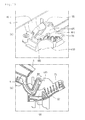
- Fig. 15 is a perspective view of the cleaner body in the state where the rotatable cover rotates at the second angle
- Fig. 16 is a view of a state in which a dust separation mechanism is separated in the state where the rotatable cover rotates at the second angle.
- the contact part 185 of the hinge body 181 may pass through the hole 623 of the first support part 621 to press the elastic member 70, thereby contracting the elastic member 70.
- the elastic member 70 is contracted, one end of the elastic member 70 may be spaced apart from the first support part 621.
- the elastic member 70 may push the contact part 185 of the hinge body 181 by the elastic force of the elastic member 70 as illustrated 13.
- the rotatable cover 15 may automatically rotate upward with respect to the hinge shaft 186.
- the elastic member 70 pushes the contact part 185 of the hinge body 181, when the rotatable cover 15 rotates at a first angle ⁇ 1 with respect to the hinge shaft 186, the elastic member 70 may contact the first support part 621. Then, the elastic member 70 may be stopped.
- an end of the contact part 185 of the hinge body 181 may be disposed in the hole 623 of the first support part 621 to contact one end of the elastic member 70.
- the elastic member 70 may have an elastic force greater than the downward rotation force due to the self-weight of the rotatable cover 15.
- the rotatable cover 15 may be maintained to the rotating state thereof by the elastic member 70 in the state where the rotatable cover 15 rotates at the first angle.
- the rotatable cover 15 when the user lifts the rotatable cover 15 upward in the state of the Fig. 13 , the rotatable cover 15 may rotate upward with respect to the hinge shaft 186 of the hinge body 181.
- the contact part 185 when the rotatable cover 15 rotates upward at the first rotation position, the contact part 185 may be spaced apart from the elastic member 70 to fall out the hole 623.
- the hinge body 181 While the rotatable cover 15 rotates upward, the hinge body 181 may contact the support protrusion 636 to interfere with the support protrusion 636. In this state, if the rotation force is further applied to the rotatable cover 15, the hinge body 181 and/or the support rib 634 may be elastically deformed to release the interference between the support protrusion 636 and the hinge body 181. Also, when the force for rotating the rotatable cover 15 upward is removed in the state where the rotatable cover 15 rotates at the second angle ⁇ 2, the hinge body 181 of the rotatable cover 15 may be supported by the support protrusion 636 and maintained in the opened state thereof.
- the hinge body 181 or the support rib 634 may not be elastically deformed by the self-weight thereof and be maintained in the state in which the hinge body 181 is seated on the support protrusion 636.
- the dust separation mechanism 20 may be separated from the cleaner body 10.
- the dust separation mechanism 20 may be separated together with an air flow guide 80.
- the air flow guide 80 may be separably connected to a lower portion of the dust separation mechanism 20.
- the air flow guide 80 may guide air discharged from the dust separation mechanism 20 toward the suction motor and include a filter.
- the dust container since the rotatable cover is maintained in the rotating state (opened state) by the opening maintenance unit, the dust container may be easily mounted on or separated from the mount part without interfering with the rotatable cover.
- the rotatable cover is maintained in the opened state at the first rotation position when the rotatable cover is not mounted on the dust container or is not coupled to the dust container, whether the dust container is mounted, or whether the rotatable cover is coupled to the dust container may be easily confirmed.
- the rotatable cover including the power transmission part is maintained in the rotating state by the opening maintenance unit, the interference between the dust container and the power transmission part while the dust container is mounted on the mount part may be prevented to prevent the power transmission part from being damaged.
- the opening maintenance unit includes the first and second opening maintenance parts in the foregoing embodiment, the present disclosure is not limited thereto.
- the opening maintenance unit may include only one of the first and second opening maintenance parts according to a kind of cleaner.
Landscapes
- Engineering & Computer Science (AREA)
- Mechanical Engineering (AREA)
- Filters For Electric Vacuum Cleaners (AREA)
- Refuse Collection And Transfer (AREA)
Applications Claiming Priority (1)
| Application Number | Priority Date | Filing Date | Title |
|---|---|---|---|
| KR20130083467A KR101495732B1 (ko) | 2013-07-16 | 2013-07-16 | 진공 청소기 |
Publications (2)
| Publication Number | Publication Date |
|---|---|
| EP2826410A1 true EP2826410A1 (de) | 2015-01-21 |
| EP2826410B1 EP2826410B1 (de) | 2019-09-04 |
Family
ID=51167725
Family Applications (1)
| Application Number | Title | Priority Date | Filing Date |
|---|---|---|---|
| EP14176453.0A Active EP2826410B1 (de) | 2013-07-16 | 2014-07-10 | Staubsauger |
Country Status (4)
| Country | Link |
|---|---|
| EP (1) | EP2826410B1 (de) |
| KR (1) | KR101495732B1 (de) |
| CN (1) | CN104287674B (de) |
| RU (1) | RU2577218C2 (de) |
Cited By (1)
| Publication number | Priority date | Publication date | Assignee | Title |
|---|---|---|---|---|
| US11419468B2 (en) | 2017-06-19 | 2022-08-23 | Tti (Macao Commercial Offshore) Limited | Dirt separation device |
Families Citing this family (16)
| Publication number | Priority date | Publication date | Assignee | Title |
|---|---|---|---|---|
| TWI653962B (zh) | 2016-02-29 | 2019-03-21 | Lg電子股份有限公司 | 真空吸塵器 |
| AU2017227412B2 (en) | 2016-02-29 | 2020-01-23 | Lg Electronics Inc. | Vacuum cleaner |
| TWI664944B (zh) | 2016-02-29 | 2019-07-11 | Lg電子股份有限公司 | 真空吸塵器 |
| TWI636758B (zh) * | 2016-02-29 | 2018-10-01 | Lg電子股份有限公司 | 真空吸塵器 |
| GB2566613B (en) * | 2016-02-29 | 2021-03-10 | Lg Electronics Inc | Vacuum cleaner |
| DE202017000985U1 (de) | 2016-02-29 | 2017-05-29 | Lg Electronics Inc. | Staubsauger |
| TWI637718B (zh) | 2016-02-29 | 2018-10-11 | Lg電子股份有限公司 | 真空吸塵器 |
| TWI643597B (zh) | 2016-02-29 | 2018-12-11 | Lg電子股份有限公司 | 真空吸塵器 |
| GB2564035B8 (en) | 2016-02-29 | 2021-07-07 | Lg Electronics Inc | Vacuum cleaner |
| TWI641353B (zh) | 2016-02-29 | 2018-11-21 | Lg電子股份有限公司 | 真空吸塵器 |
| TWI664943B (zh) | 2016-02-29 | 2019-07-11 | Lg電子股份有限公司 | 真空吸塵器 |
| WO2017150862A1 (ko) | 2016-02-29 | 2017-09-08 | 엘지전자 주식회사 | 진공 청소기 |
| TWI643596B (zh) | 2016-02-29 | 2018-12-11 | Lg電子股份有限公司 | 真空吸塵器 |
| DE202017000984U1 (de) | 2016-02-29 | 2017-05-29 | Lg Electronics Inc. | Staubsauger |
| DE202017002619U1 (de) | 2016-05-20 | 2017-08-04 | Lg Electronics Inc. | Staubsauger |
| KR101823264B1 (ko) * | 2016-09-29 | 2018-01-29 | 엘지전자 주식회사 | 진공 청소기 및 진공 청소기용 먼지통 |
Citations (5)
| Publication number | Priority date | Publication date | Assignee | Title |
|---|---|---|---|---|
| JPH07322975A (ja) * | 1994-06-01 | 1995-12-12 | Matsushita Electric Ind Co Ltd | 電気掃除機 |
| JP2007089750A (ja) * | 2005-09-28 | 2007-04-12 | Matsushita Electric Ind Co Ltd | 電気掃除機 |
| FR2912635A3 (fr) * | 2007-02-21 | 2008-08-22 | Eta As | Aspirateur a logement variable du filtre et mecanisme de logement de filtre de cet aspirateur |
| KR20100018785A (ko) | 2008-08-07 | 2010-02-18 | 엘지전자 주식회사 | 진공 청소기 |
| EP2324748A2 (de) * | 2008-08-07 | 2011-05-25 | LG Electronics Inc. | Staubsauger |
Family Cites Families (12)
| Publication number | Priority date | Publication date | Assignee | Title |
|---|---|---|---|---|
| GB782805A (en) * | 1955-09-26 | 1957-09-11 | Electrolux Corp | Vacuum cleaners |
| DE3440910A1 (de) * | 1984-11-09 | 1986-05-15 | Licentia Patent-Verwaltungs-Gmbh, 6000 Frankfurt | Staubsauger mit einem klappbaren deckel fuer zubehoerteile |
| KR0177072B1 (ko) * | 1996-10-29 | 1999-10-01 | 대우전자주식회사 | 먼지봉투가 부착된 진공청소기의 분리형 커버 |
| KR101026028B1 (ko) * | 2007-07-16 | 2011-03-30 | 엘지전자 주식회사 | 진공 청소기 |
| CN201015570Y (zh) * | 2007-03-20 | 2008-02-06 | 王跃旦 | 吸尘器的前盖扣装置 |
| CN101278815A (zh) * | 2007-04-06 | 2008-10-08 | 乐金电子(天津)电器有限公司 | 真空吸尘器前盖打开两档限位结构 |
| CN101422340B (zh) * | 2007-10-31 | 2011-05-11 | 乐金电子(天津)电器有限公司 | 具有排气盖自动垂直开启结构的吸尘器 |
| KR100996531B1 (ko) * | 2008-07-02 | 2010-11-24 | 엘지전자 주식회사 | 진공 청소기 |
| KR101026065B1 (ko) | 2008-08-18 | 2011-04-04 | 엘지전자 주식회사 | 청소기의 커버개폐수단 및 이를 이용한 커버개폐구조 |
| GB2466625B (en) * | 2008-12-23 | 2012-10-03 | Vax Ltd | Dust receptacle for a vacuum cleaner |
| CN102334953A (zh) * | 2010-07-27 | 2012-02-01 | 乐金电子(天津)电器有限公司 | 吸尘器的集尘桶 |
| JP5931385B2 (ja) * | 2011-09-22 | 2016-06-08 | 株式会社東芝 | 電気掃除機 |
-
2013
- 2013-07-16 KR KR20130083467A patent/KR101495732B1/ko not_active Expired - Fee Related
-
2014
- 2014-07-10 EP EP14176453.0A patent/EP2826410B1/de active Active
- 2014-07-15 CN CN201410334850.5A patent/CN104287674B/zh not_active Expired - Fee Related
- 2014-07-15 RU RU2014129203/12A patent/RU2577218C2/ru active
Patent Citations (5)
| Publication number | Priority date | Publication date | Assignee | Title |
|---|---|---|---|---|
| JPH07322975A (ja) * | 1994-06-01 | 1995-12-12 | Matsushita Electric Ind Co Ltd | 電気掃除機 |
| JP2007089750A (ja) * | 2005-09-28 | 2007-04-12 | Matsushita Electric Ind Co Ltd | 電気掃除機 |
| FR2912635A3 (fr) * | 2007-02-21 | 2008-08-22 | Eta As | Aspirateur a logement variable du filtre et mecanisme de logement de filtre de cet aspirateur |
| KR20100018785A (ko) | 2008-08-07 | 2010-02-18 | 엘지전자 주식회사 | 진공 청소기 |
| EP2324748A2 (de) * | 2008-08-07 | 2011-05-25 | LG Electronics Inc. | Staubsauger |
Cited By (2)
| Publication number | Priority date | Publication date | Assignee | Title |
|---|---|---|---|---|
| US11419468B2 (en) | 2017-06-19 | 2022-08-23 | Tti (Macao Commercial Offshore) Limited | Dirt separation device |
| US11426045B2 (en) | 2017-06-19 | 2022-08-30 | Tti (Macao Commercial Offshore) Limited | Surface cleaning apparatus |
Also Published As
| Publication number | Publication date |
|---|---|
| EP2826410B1 (de) | 2019-09-04 |
| KR20150009251A (ko) | 2015-01-26 |
| RU2577218C2 (ru) | 2016-03-10 |
| CN104287674B (zh) | 2017-04-12 |
| KR101495732B1 (ko) | 2015-02-25 |
| RU2014129203A (ru) | 2016-02-10 |
| CN104287674A (zh) | 2015-01-21 |
Similar Documents
| Publication | Publication Date | Title |
|---|---|---|
| EP2826410B1 (de) | Staubsauger | |
| KR101411685B1 (ko) | 진공 청소기 | |
| US20240197126A1 (en) | Cleaner | |
| US8713752B2 (en) | Vacuum cleaner | |
| KR101653459B1 (ko) | 진공 청소기 및 집진장치 | |
| CN111973055B (zh) | 吸尘器 | |
| EP2324748B1 (de) | Staubsauger | |
| EP2862492B1 (de) | Staubsauger | |
| KR20210015128A (ko) | 청소기 | |
| KR20240049238A (ko) | 청소기 | |
| EP2979601B1 (de) | Reiniger | |
| KR20230075162A (ko) | 진공 청소기와 집진 스테이션을 포함하는 청소 장치 | |
| EP2316323B1 (de) | Staubsauger | |
| KR102097439B1 (ko) | 청소기 | |
| KR102676424B1 (ko) | 청소기 | |
| KR20200062085A (ko) | 청소기 |
Legal Events
| Date | Code | Title | Description |
|---|---|---|---|
| 17P | Request for examination filed |
Effective date: 20140710 |
|
| AK | Designated contracting states |
Kind code of ref document: A1 Designated state(s): AL AT BE BG CH CY CZ DE DK EE ES FI FR GB GR HR HU IE IS IT LI LT LU LV MC MK MT NL NO PL PT RO RS SE SI SK SM TR |
|
| AX | Request for extension of the european patent |
Extension state: BA ME |
|
| PUAI | Public reference made under article 153(3) epc to a published international application that has entered the european phase |
Free format text: ORIGINAL CODE: 0009012 |
|
| R17P | Request for examination filed (corrected) |
Effective date: 20150520 |
|
| RBV | Designated contracting states (corrected) |
Designated state(s): AL AT BE BG CH CY CZ DE DK EE ES FI FR GB GR HR HU IE IS IT LI LT LU LV MC MK MT NL NO PL PT RO RS SE SI SK SM TR |
|
| GRAP | Despatch of communication of intention to grant a patent |
Free format text: ORIGINAL CODE: EPIDOSNIGR1 |
|
| STAA | Information on the status of an ep patent application or granted ep patent |
Free format text: STATUS: GRANT OF PATENT IS INTENDED |
|
| INTG | Intention to grant announced |
Effective date: 20190131 |
|
| RAP1 | Party data changed (applicant data changed or rights of an application transferred) |
Owner name: LG ELECTRONICS INC. |
|
| GRAS | Grant fee paid |
Free format text: ORIGINAL CODE: EPIDOSNIGR3 |
|
| GRAA | (expected) grant |
Free format text: ORIGINAL CODE: 0009210 |
|
| STAA | Information on the status of an ep patent application or granted ep patent |
Free format text: STATUS: THE PATENT HAS BEEN GRANTED |
|
| AK | Designated contracting states |
Kind code of ref document: B1 Designated state(s): AL AT BE BG CH CY CZ DE DK EE ES FI FR GB GR HR HU IE IS IT LI LT LU LV MC MK MT NL NO PL PT RO RS SE SI SK SM TR |
|
| REG | Reference to a national code |
Ref country code: GB Ref legal event code: FG4D |
|
| REG | Reference to a national code |
Ref country code: CH Ref legal event code: EP |
|
| REG | Reference to a national code |
Ref country code: AT Ref legal event code: REF Ref document number: 1174175 Country of ref document: AT Kind code of ref document: T Effective date: 20190915 |
|
| REG | Reference to a national code |
Ref country code: DE Ref legal event code: R096 Ref document number: 602014052855 Country of ref document: DE |
|
| REG | Reference to a national code |
Ref country code: IE Ref legal event code: FG4D |
|
| REG | Reference to a national code |
Ref country code: NL Ref legal event code: MP Effective date: 20190904 |
|
| REG | Reference to a national code |
Ref country code: LT Ref legal event code: MG4D |
|
| PG25 | Lapsed in a contracting state [announced via postgrant information from national office to epo] |
Ref country code: LT Free format text: LAPSE BECAUSE OF FAILURE TO SUBMIT A TRANSLATION OF THE DESCRIPTION OR TO PAY THE FEE WITHIN THE PRESCRIBED TIME-LIMIT Effective date: 20190904 Ref country code: SE Free format text: LAPSE BECAUSE OF FAILURE TO SUBMIT A TRANSLATION OF THE DESCRIPTION OR TO PAY THE FEE WITHIN THE PRESCRIBED TIME-LIMIT Effective date: 20190904 Ref country code: FI Free format text: LAPSE BECAUSE OF FAILURE TO SUBMIT A TRANSLATION OF THE DESCRIPTION OR TO PAY THE FEE WITHIN THE PRESCRIBED TIME-LIMIT Effective date: 20190904 Ref country code: NO Free format text: LAPSE BECAUSE OF FAILURE TO SUBMIT A TRANSLATION OF THE DESCRIPTION OR TO PAY THE FEE WITHIN THE PRESCRIBED TIME-LIMIT Effective date: 20191204 Ref country code: BG Free format text: LAPSE BECAUSE OF FAILURE TO SUBMIT A TRANSLATION OF THE DESCRIPTION OR TO PAY THE FEE WITHIN THE PRESCRIBED TIME-LIMIT Effective date: 20191204 Ref country code: HR Free format text: LAPSE BECAUSE OF FAILURE TO SUBMIT A TRANSLATION OF THE DESCRIPTION OR TO PAY THE FEE WITHIN THE PRESCRIBED TIME-LIMIT Effective date: 20190904 |
|
| PG25 | Lapsed in a contracting state [announced via postgrant information from national office to epo] |
Ref country code: RS Free format text: LAPSE BECAUSE OF FAILURE TO SUBMIT A TRANSLATION OF THE DESCRIPTION OR TO PAY THE FEE WITHIN THE PRESCRIBED TIME-LIMIT Effective date: 20190904 Ref country code: LV Free format text: LAPSE BECAUSE OF FAILURE TO SUBMIT A TRANSLATION OF THE DESCRIPTION OR TO PAY THE FEE WITHIN THE PRESCRIBED TIME-LIMIT Effective date: 20190904 Ref country code: GR Free format text: LAPSE BECAUSE OF FAILURE TO SUBMIT A TRANSLATION OF THE DESCRIPTION OR TO PAY THE FEE WITHIN THE PRESCRIBED TIME-LIMIT Effective date: 20191205 Ref country code: AL Free format text: LAPSE BECAUSE OF FAILURE TO SUBMIT A TRANSLATION OF THE DESCRIPTION OR TO PAY THE FEE WITHIN THE PRESCRIBED TIME-LIMIT Effective date: 20190904 Ref country code: ES Free format text: LAPSE BECAUSE OF FAILURE TO SUBMIT A TRANSLATION OF THE DESCRIPTION OR TO PAY THE FEE WITHIN THE PRESCRIBED TIME-LIMIT Effective date: 20190904 |
|
| REG | Reference to a national code |
Ref country code: AT Ref legal event code: MK05 Ref document number: 1174175 Country of ref document: AT Kind code of ref document: T Effective date: 20190904 |
|
| PG25 | Lapsed in a contracting state [announced via postgrant information from national office to epo] |
Ref country code: PL Free format text: LAPSE BECAUSE OF FAILURE TO SUBMIT A TRANSLATION OF THE DESCRIPTION OR TO PAY THE FEE WITHIN THE PRESCRIBED TIME-LIMIT Effective date: 20190904 Ref country code: NL Free format text: LAPSE BECAUSE OF FAILURE TO SUBMIT A TRANSLATION OF THE DESCRIPTION OR TO PAY THE FEE WITHIN THE PRESCRIBED TIME-LIMIT Effective date: 20190904 Ref country code: AT Free format text: LAPSE BECAUSE OF FAILURE TO SUBMIT A TRANSLATION OF THE DESCRIPTION OR TO PAY THE FEE WITHIN THE PRESCRIBED TIME-LIMIT Effective date: 20190904 Ref country code: IT Free format text: LAPSE BECAUSE OF FAILURE TO SUBMIT A TRANSLATION OF THE DESCRIPTION OR TO PAY THE FEE WITHIN THE PRESCRIBED TIME-LIMIT Effective date: 20190904 Ref country code: PT Free format text: LAPSE BECAUSE OF FAILURE TO SUBMIT A TRANSLATION OF THE DESCRIPTION OR TO PAY THE FEE WITHIN THE PRESCRIBED TIME-LIMIT Effective date: 20200106 Ref country code: RO Free format text: LAPSE BECAUSE OF FAILURE TO SUBMIT A TRANSLATION OF THE DESCRIPTION OR TO PAY THE FEE WITHIN THE PRESCRIBED TIME-LIMIT Effective date: 20190904 Ref country code: EE Free format text: LAPSE BECAUSE OF FAILURE TO SUBMIT A TRANSLATION OF THE DESCRIPTION OR TO PAY THE FEE WITHIN THE PRESCRIBED TIME-LIMIT Effective date: 20190904 |
|
| PG25 | Lapsed in a contracting state [announced via postgrant information from national office to epo] |
Ref country code: SM Free format text: LAPSE BECAUSE OF FAILURE TO SUBMIT A TRANSLATION OF THE DESCRIPTION OR TO PAY THE FEE WITHIN THE PRESCRIBED TIME-LIMIT Effective date: 20190904 Ref country code: CZ Free format text: LAPSE BECAUSE OF FAILURE TO SUBMIT A TRANSLATION OF THE DESCRIPTION OR TO PAY THE FEE WITHIN THE PRESCRIBED TIME-LIMIT Effective date: 20190904 Ref country code: IS Free format text: LAPSE BECAUSE OF FAILURE TO SUBMIT A TRANSLATION OF THE DESCRIPTION OR TO PAY THE FEE WITHIN THE PRESCRIBED TIME-LIMIT Effective date: 20200224 Ref country code: SK Free format text: LAPSE BECAUSE OF FAILURE TO SUBMIT A TRANSLATION OF THE DESCRIPTION OR TO PAY THE FEE WITHIN THE PRESCRIBED TIME-LIMIT Effective date: 20190904 |
|
| REG | Reference to a national code |
Ref country code: DE Ref legal event code: R097 Ref document number: 602014052855 Country of ref document: DE |
|
| PLBE | No opposition filed within time limit |
Free format text: ORIGINAL CODE: 0009261 |
|
| STAA | Information on the status of an ep patent application or granted ep patent |
Free format text: STATUS: NO OPPOSITION FILED WITHIN TIME LIMIT |
|
| PG2D | Information on lapse in contracting state deleted |
Ref country code: IS |
|
| PG25 | Lapsed in a contracting state [announced via postgrant information from national office to epo] |
Ref country code: DK Free format text: LAPSE BECAUSE OF FAILURE TO SUBMIT A TRANSLATION OF THE DESCRIPTION OR TO PAY THE FEE WITHIN THE PRESCRIBED TIME-LIMIT Effective date: 20190904 Ref country code: IS Free format text: LAPSE BECAUSE OF FAILURE TO SUBMIT A TRANSLATION OF THE DESCRIPTION OR TO PAY THE FEE WITHIN THE PRESCRIBED TIME-LIMIT Effective date: 20200105 |
|
| 26N | No opposition filed |
Effective date: 20200605 |
|
| PG25 | Lapsed in a contracting state [announced via postgrant information from national office to epo] |
Ref country code: SI Free format text: LAPSE BECAUSE OF FAILURE TO SUBMIT A TRANSLATION OF THE DESCRIPTION OR TO PAY THE FEE WITHIN THE PRESCRIBED TIME-LIMIT Effective date: 20190904 |
|
| PGFP | Annual fee paid to national office [announced via postgrant information from national office to epo] |
Ref country code: GB Payment date: 20200608 Year of fee payment: 7 |
|
| PGFP | Annual fee paid to national office [announced via postgrant information from national office to epo] |
Ref country code: DE Payment date: 20200605 Year of fee payment: 7 |
|
| PG25 | Lapsed in a contracting state [announced via postgrant information from national office to epo] |
Ref country code: MC Free format text: LAPSE BECAUSE OF FAILURE TO SUBMIT A TRANSLATION OF THE DESCRIPTION OR TO PAY THE FEE WITHIN THE PRESCRIBED TIME-LIMIT Effective date: 20190904 |
|
| REG | Reference to a national code |
Ref country code: CH Ref legal event code: PL |
|
| REG | Reference to a national code |
Ref country code: BE Ref legal event code: MM Effective date: 20200731 |
|
| PG25 | Lapsed in a contracting state [announced via postgrant information from national office to epo] |
Ref country code: CH Free format text: LAPSE BECAUSE OF NON-PAYMENT OF DUE FEES Effective date: 20200731 Ref country code: LI Free format text: LAPSE BECAUSE OF NON-PAYMENT OF DUE FEES Effective date: 20200731 Ref country code: LU Free format text: LAPSE BECAUSE OF NON-PAYMENT OF DUE FEES Effective date: 20200710 Ref country code: FR Free format text: LAPSE BECAUSE OF NON-PAYMENT OF DUE FEES Effective date: 20200731 |
|
| PG25 | Lapsed in a contracting state [announced via postgrant information from national office to epo] |
Ref country code: BE Free format text: LAPSE BECAUSE OF NON-PAYMENT OF DUE FEES Effective date: 20200731 |
|
| PG25 | Lapsed in a contracting state [announced via postgrant information from national office to epo] |
Ref country code: IE Free format text: LAPSE BECAUSE OF NON-PAYMENT OF DUE FEES Effective date: 20200710 |
|
| REG | Reference to a national code |
Ref country code: DE Ref legal event code: R119 Ref document number: 602014052855 Country of ref document: DE |
|
| GBPC | Gb: european patent ceased through non-payment of renewal fee |
Effective date: 20210710 |
|
| PG25 | Lapsed in a contracting state [announced via postgrant information from national office to epo] |
Ref country code: GB Free format text: LAPSE BECAUSE OF NON-PAYMENT OF DUE FEES Effective date: 20210710 Ref country code: DE Free format text: LAPSE BECAUSE OF NON-PAYMENT OF DUE FEES Effective date: 20220201 |
|
| PG25 | Lapsed in a contracting state [announced via postgrant information from national office to epo] |
Ref country code: TR Free format text: LAPSE BECAUSE OF FAILURE TO SUBMIT A TRANSLATION OF THE DESCRIPTION OR TO PAY THE FEE WITHIN THE PRESCRIBED TIME-LIMIT Effective date: 20190904 Ref country code: MT Free format text: LAPSE BECAUSE OF FAILURE TO SUBMIT A TRANSLATION OF THE DESCRIPTION OR TO PAY THE FEE WITHIN THE PRESCRIBED TIME-LIMIT Effective date: 20190904 Ref country code: CY Free format text: LAPSE BECAUSE OF FAILURE TO SUBMIT A TRANSLATION OF THE DESCRIPTION OR TO PAY THE FEE WITHIN THE PRESCRIBED TIME-LIMIT Effective date: 20190904 |
|
| PG25 | Lapsed in a contracting state [announced via postgrant information from national office to epo] |
Ref country code: MK Free format text: LAPSE BECAUSE OF FAILURE TO SUBMIT A TRANSLATION OF THE DESCRIPTION OR TO PAY THE FEE WITHIN THE PRESCRIBED TIME-LIMIT Effective date: 20190904 |