EP2826518A1 - Module d'aiguille et appareil destiné à piquer la peau - Google Patents
Module d'aiguille et appareil destiné à piquer la peau Download PDFInfo
- Publication number
- EP2826518A1 EP2826518A1 EP13003581.9A EP13003581A EP2826518A1 EP 2826518 A1 EP2826518 A1 EP 2826518A1 EP 13003581 A EP13003581 A EP 13003581A EP 2826518 A1 EP2826518 A1 EP 2826518A1
- Authority
- EP
- European Patent Office
- Prior art keywords
- needle module
- holder
- drive unit
- needle
- piercing means
- Prior art date
- Legal status (The legal status is an assumption and is not a legal conclusion. Google has not performed a legal analysis and makes no representation as to the accuracy of the status listed.)
- Granted
Links
- 230000033001 locomotion Effects 0.000 claims abstract description 22
- 230000003252 repetitive effect Effects 0.000 claims abstract description 8
- 230000008878 coupling Effects 0.000 claims description 41
- 238000010168 coupling process Methods 0.000 claims description 41
- 238000005859 coupling reaction Methods 0.000 claims description 41
- 210000002105 tongue Anatomy 0.000 claims description 6
- 239000011324 bead Substances 0.000 claims description 4
- 239000013013 elastic material Substances 0.000 claims description 2
- 239000003302 ferromagnetic material Substances 0.000 claims description 2
- 239000003814 drug Substances 0.000 description 6
- 229940079593 drug Drugs 0.000 description 4
- 239000002184 metal Substances 0.000 description 4
- 230000003534 oscillatory effect Effects 0.000 description 4
- 230000001681 protective effect Effects 0.000 description 4
- 208000027418 Wounds and injury Diseases 0.000 description 3
- 230000005540 biological transmission Effects 0.000 description 3
- 230000006378 damage Effects 0.000 description 3
- 230000005294 ferromagnetic effect Effects 0.000 description 3
- 208000014674 injury Diseases 0.000 description 3
- 239000000463 material Substances 0.000 description 3
- 238000000926 separation method Methods 0.000 description 3
- 238000005452 bending Methods 0.000 description 2
- 230000008859 change Effects 0.000 description 2
- 238000010276 construction Methods 0.000 description 2
- 230000005489 elastic deformation Effects 0.000 description 2
- 238000011156 evaluation Methods 0.000 description 2
- 230000002427 irreversible effect Effects 0.000 description 2
- 230000005291 magnetic effect Effects 0.000 description 2
- 239000000696 magnetic material Substances 0.000 description 2
- 239000000049 pigment Substances 0.000 description 2
- 208000002193 Pain Diseases 0.000 description 1
- 230000004913 activation Effects 0.000 description 1
- 239000000853 adhesive Substances 0.000 description 1
- 230000001070 adhesive effect Effects 0.000 description 1
- 239000002390 adhesive tape Substances 0.000 description 1
- 230000008901 benefit Effects 0.000 description 1
- 239000003795 chemical substances by application Substances 0.000 description 1
- 239000007822 coupling agent Substances 0.000 description 1
- 238000012864 cross contamination Methods 0.000 description 1
- 238000013500 data storage Methods 0.000 description 1
- 238000001746 injection moulding Methods 0.000 description 1
- 238000000034 method Methods 0.000 description 1
- 230000010355 oscillation Effects 0.000 description 1
- 238000004806 packaging method and process Methods 0.000 description 1
- 244000052769 pathogen Species 0.000 description 1
- 230000000485 pigmenting effect Effects 0.000 description 1
- 230000008569 process Effects 0.000 description 1
- 239000000126 substance Substances 0.000 description 1
- 238000002255 vaccination Methods 0.000 description 1
Images




Classifications
-
- A—HUMAN NECESSITIES
- A61—MEDICAL OR VETERINARY SCIENCE; HYGIENE
- A61M—DEVICES FOR INTRODUCING MEDIA INTO, OR ONTO, THE BODY; DEVICES FOR TRANSDUCING BODY MEDIA OR FOR TAKING MEDIA FROM THE BODY; DEVICES FOR PRODUCING OR ENDING SLEEP OR STUPOR
- A61M37/00—Other apparatus for introducing media into the body; Percutany, i.e. introducing medicines into the body by diffusion through the skin
- A61M37/0076—Tattooing apparatus
-
- A—HUMAN NECESSITIES
- A61—MEDICAL OR VETERINARY SCIENCE; HYGIENE
- A61M—DEVICES FOR INTRODUCING MEDIA INTO, OR ONTO, THE BODY; DEVICES FOR TRANSDUCING BODY MEDIA OR FOR TAKING MEDIA FROM THE BODY; DEVICES FOR PRODUCING OR ENDING SLEEP OR STUPOR
- A61M2205/00—General characteristics of the apparatus
- A61M2205/10—General characteristics of the apparatus with powered movement mechanisms
- A61M2205/106—General characteristics of the apparatus with powered movement mechanisms reciprocating
-
- A—HUMAN NECESSITIES
- A61—MEDICAL OR VETERINARY SCIENCE; HYGIENE
- A61M—DEVICES FOR INTRODUCING MEDIA INTO, OR ONTO, THE BODY; DEVICES FOR TRANSDUCING BODY MEDIA OR FOR TAKING MEDIA FROM THE BODY; DEVICES FOR PRODUCING OR ENDING SLEEP OR STUPOR
- A61M2205/00—General characteristics of the apparatus
- A61M2205/82—Internal energy supply devices
- A61M2205/8206—Internal energy supply devices battery-operated
Definitions
- the present invention relates to a needle module provided with a drive device to a device for piercing the skin, e.g. for permanent makeup or tattoos, can be coupled.
- a typical hand-held device for piercing the skin consists of a drive unit and a releasably connected needle module.
- the drive unit typically includes a motor, a transmission, and an output for generating oscillatory reciprocation of the needle.
- the needle module includes the needle or needle system received in a needle holder.
- the needle holder is connectable to the drive unit.
- the drive unit usually includes a push rod with a special recording, in which the needle holder, depending on the manufacturer, inserted, plugged and / or jammed.
- the needle may be a specifically shaped, single needle or a needle system, ie a collection of multiple needles.
- the needle performs an oscillatory reciprocating motion with a user adjustable speed and plunge depth during piercing.
- the plunge process thus takes place in a defined manner.
- the goal is to introduce a given dye (or drug) by oscillatory piercing deeper skin layers.
- the needle is either regularly in the Immersed dye or drug or the dye or drug is disposed in a reservoir in the needle module.
- a - usually sterile - needle is connected to the drive unit of the device. After completion of the treatment, the needle should be disposed of with a needle guide.
- Such devices in particular hand-held devices for piercing the skin are known per se and, for example, in EP 1 743 673 A1 and EP 1 872 823 A1 described.
- the resistance to puncture should be measured and responded via a connected to the handset controller to a change in resistance with a change in the repetition of the puncture.
- the EP 1 872 823 A1 proposes to provide identification means on the needle module, which are evaluated by an evaluation device on the drive unit. As a result, especially the coupling of a needle module incompatible with the drive unit should be prevented. In addition, however, information about permissible operating parameters of the needle module can also be introduced and evaluated. Furthermore, identification means in the form of electronic data storage devices, eg RFID chips, allow unauthorized multiple use of a needle module to be blocked. Such a fuse is very desirable, but require electronic identification means a corresponding evaluation device, whereby the devices are considerably more expensive. In addition, electronic systems are complex, prone to failure and manipulatable. There is therefore a need for simple ways to secure.
- a needle module comprising a piercing means on a holder, which is releasably coupled to a drive unit, so that a repetitive pushing movement for extending and retracting the piercing means is transmitted by a driving force exerted by the drive unit on the holder , wherein the holder has a securing device which blocks the piercing means mechanically irreversible after releasing the needle module of the drive unit so that it can not be extended out of the needle module.
- the invention also relates to a device, in particular a hand device, for piercing the skin, comprising a drive unit and a needle module, wherein the drive unit comprises a motor and coupling means, and the needle module comprises a piercing means on a holder, which is releasably coupled to the drive unit, such that a repetitive pushing movement for extending and retracting the piercing means is transmitted by a driving force exerted on the holder by the drive unit, wherein the holder has a securing device which mechanically locks the piercing means so irreversibly after releasing the needle module from the drive unit can not be extended out of the needle module.
- needle module and apparatus according to the invention ensure that a needle module is not accidentally used multiple times. Such multiple use carries the risk of cross-contamination by transmitting pathogens from one patient to another.
- a great advantage of the invention is that the risk of injury is significantly reduced when removing and disposing of the needle module. An accidental self-piercing or stinging other people in the environment on a freely accessible, soiled needle is almost impossible.
- the needle module according to the invention has a needle as a piercing means, or a needle system with two, three or even more needles.
- the needles are formed in a conventional manner. It is expedient if the piercing means is covered with a protective cap before use, which is withdrawn only after the coupling of the needle module to the drive unit. A protective cap is particularly preferred when the piercing means protrudes from the needle module before use. In addition, it is preferred if the needle module is sterilized and / or stored in a package until use.
- the needle module has a holder for the piercing means, which can be coupled to the drive unit in a detachable manner.
- the repetitive thrusting movements generated by the drive unit are transmitted to the piercing means.
- the piercing agent is repeatedly moved to pierce the skin out of the needle module and then into it again.
- the coupling can be structurally different.
- the drive unit has a coupling means, for example, preferably a push rod on.
- a coupling means for example, preferably a push rod on.
- corresponding parts of releasable connecting means are formed as coupling elements on the coupling means and the holder.
- the holder or the coupling means end have a ball which is positively connected to a dome on the coupling means or the holder.
- a ferromagnetic metal be integrated, which is attracted by a magnet in the drive unit (in the holder), whereby a frictional connection arises.
- Other possibilities of coupling are in particular the use of Velcro strips and other adhesive tapes.
- the re-releasable connection remains during the piercing by a dynamic, oscillatory reciprocating motion of the push rod of defined oscillation width and is to be dimensioned according to the present, dynamic forces.
- the fixation of the needle or needles on the holder takes place in a manner known per se.
- the needle module further comprises an outer cover, for example a closed housing.
- the housing is designed in two parts and comprises a top module at the top, in which substantially the piercing means, as well as a base module in which substantially the holder and is arranged. Due to the bipartition, the housing can be inexpensively manufactured by injection molding.
- the cover overlaps with a housing of the drive unit, so that the area in which the holder is coupled to the drive unit is shielded not only during operation but also during the coupling to the outside.
- a guide of the piercing means or the holder is formed.
- the guide can be formed integrally with the cover, or preferably as a separate part which is fixed to the cover. It is particularly preferred if the guide surrounds the holder in an annular manner.
- the guide is fixed with a bead on the outer circumference in a groove on the cover. A tour can also be realized elsewhere.
- the inventively provided securing device is active in releasing the coupling of needle module and drive unit by a mechanical blockage of the piercing means is generated. After activation of the securing device, it is no longer possible to move the piercing means out of the needle module. This excludes reuse and injury risk.
- the security device consists e.g. from a projection and a securing element. Of these two, one part on the holder and the other part on the cover of the needle module are positioned relative to each other, that the securing element before and during use in all positions of the piercing from the side of the piercing ago before the projection, and when removing the Needle module is moved behind the projection.
- the securing element is wholly or partly formed from an elastic material.
- the dimensions of the projection and Sich ceremoniesslement be tuned so that the fuse element can not be moved past the projection without effort.
- the force which is necessary when the needle module is withdrawn from the drive unit for moving the securing element behind the projection is smaller than the adhesion force of the coupling.
- an elastic deformation takes place, so that it can be moved past the projection. As soon as it has passed the projection, it deforms back and can then no longer force past the projection into the starting position without effort.
- the spatial configuration of the projection and the securing element is preferably chosen such that the force wall for moving past the projection is smaller than a force required for a return movement.
- This can be realized, for example, by means of springs or spring tongues as a securing element, which can be easily pressed in one direction, but which can be pressed in the direction of rotation Spread the opposite direction and thus virtually exclude withdrawal.
- the force required for the passage of the securing element from the position of use behind the projection is low.
- the elastic securing element is in a first preferred embodiment, a spring, spring tongue or a barb.
- the projection may e.g. a bead or collar, preferably it is formed by the guide. But it is also possible to design projection and leadership as separate parts.
- the securing element is formed by a barb or a spring tongue, or more thereof, on the holder and the projection is formed by the guide.
- a ring of spring tongues on the cover, preferably on the guide, of the needle module is provided as a securing element and the projection is a bead, collar or O-ring on the holder.
- the mechanical blockage takes place in that the piercing means is pulled out of its outlet opening in the cover of the needle module when uncoupling from the drive unit and the holder has a radial clearance.
- the piercing means is no longer centered in the exit aperture, it can no longer be returned to the exit aperture since the retainer has no centering sufficient to hit the aperture, or even is forced out of this centered position by means of a resilient member or non-centered bearing.
- the cover of the needle module further complicates a meeting of the opening by being located at the tip of a cone pointing towards the drive unit with the tip.
- the needle module comprises a locking device.
- the material of the locking device can, for. As plastic and / or metal.
- the piercing means is fixed by the locking device.
- the locking device is released, so that the fixation of the piercing means is canceled.
- the locking device may be a pin, pin or web, which engages in a recess on the holder of the piercing means or is secured to the holder. To release, the pin / pin is pulled out or the web removed, e.g. canceled or bent away.
- the locking device facilitates the attachment of the needle module to the drive unit.
- the locking device is integrated into the guide by the guide having at one point an opening through which a pin / bolt engages in a recess on the holder.
- the drive unit comprises a coupling means, preferably a push rod, for transmitting the pushing movement to the holder in the needle module.
- a coupling means preferably a push rod
- a transmission is provided.
- the drive unit typically forms the handle with which the device is held for piercing the skin.
- the device also includes a power supply.
- a drive in particular an electric motor, is provided in the drive unit, which generates the repetitive pushing movement.
- the drive unit is powered, if necessary via a power supply, by a power cord with power, or operated with a battery or a battery.
- Switch and controller can be housed in the drive unit or in a control unit. If a control unit is provided, an approximately necessary power supply is preferably integrated in this.
- the on / off switch is preferably located on the drive unit. It can be designed as a pressure switch for safety reasons, so that the pushing movement is only provided or transmitted to the piercing means as long as the operator keeps the switch pressed.
- Needle module and drive unit can be secured in a conventional manner against the use of unsuitable combinations of the two, unless the specific coupling already prevents the use of a not provided for the drive unit needle module.
- a reservoir for a substance to be applied to the skin can be integrated in the needle module. This is for example advantageous for vaccinations. But even for the application of permanent make-up, it may be advantageous that a usual required amount of pigment is present in a reservoir in the needle module.
- FIG. 1 the structure of a handset 1 is shown schematically.
- the needle module 2 comprises a needle as a piercing means 3, which is received in a holder 4.
- the drive unit 5 comprises a motor 6, which is releasably coupled via a gear 7 and a coupling means 8 in the form of a push rod with the holder 4.
- the coupling of the holder 4 to the drive unit 5 is effected by a magnet 9 in the push rod 8 and a ferromagnetic material 10 in the holder 4.
- the needle module 2 a guide 12, which is also part of a locking device 11 by the guide 12 has an opening 11 a, in which a bolt 11 b is arranged, which can engage in a recess 11 c on the holder 4.
- the bolt 11 a With the help of the bolt 11 a, the holder 4 is fixed until use.
- the coupling takes place only finally when the pin 11 a is pulled out of the recess 11 c. Only then can the holder 4 with the push rod 8 come into direct contact.
- the securing device consists of a projection, which is formed by the guide 12, and the securing element 13.
- the needle 3 is covered by the protective cap 14 until it is used. It can also be seen that the needle module 2 in this case has a two-part cover, which is composed of the base module 15 and the top module 16.
- the needle 3 is usually firmly and permanently connected to the holder 4.
- the operator selects a needle module 2 having a desired needle geometry and diameter.
- several needle modules 2 with different needles 3 are usually used.
- Fig. 2 is coupled with the drive unit 5 needle module 2 again shown enlarged.
- the holder 4 includes a coupling element, which allows a simple, releasable connection with the push rod 8 of the output unit 5.
- Constructive realizations of the coupling element are, for example, positive snap connection elements, clamping and adhesive connections, Velcro or magnetic elements.
- FIG. 3 again the needle module 2 is shown above, with lines AA and BB are shown. The two cross sections along these lines are below in FIG. 3 to see.
- section along AA is to recognize that the guide 12 and the cover 15 of the needle module 2 as part of the locking device 11 a Have breakthrough 11b, the in FIG. 2 shown bolt 11 a can pass through then to engage in the recess 11 c of the holder 4 and fix the holder 4 so.
- FIG. 3 It can also be seen that the holder 4 is guided in the guide 12, which also forms the projection for the securing device.
- the holder is flattened in the region between the coupling element 10 and the fixation of the piercing 3. As can be seen in the section BB, this facilitates the dimensioning of the securing element 13 and gives it room for its elastic deformation while it is pulled past the guide 12 (which forms the projection).
- a groove could be provided in which the securing element can deform.
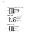
- Fig. 4 shows various examples of coupling elements for the device 1 according to the invention.
- the magnetic coupling is shown, of course, the magnet in the holder and the magnetic material can be present on the push rod.
- Fig. 4b illustrates a coupling via dome 17 and ball 18.
- the corresponding parts hook component 19 and loop component 20 of a hook and loop fastener to the bracket and drive unit are provided.
- these coupling means can also be arranged reciprocally.
- FIG. 5 shows how the geometric location of the locking device 11 in the direction of movement is arbitrary.
- Fig. 6 a to d illustrates examples of embodiments of locking devices 11 schematically.
- the device 11 should thereby have sufficient mechanical strength in material and deformation (bending stiffness), so that during the attachment of the needle module 2 on the drive unit 5, the holder 4 remains in its initial position.
- FIGS. 7a to c the needle module 2 is shown during and after the treatment. After attaching needle module 2 and before starting treatment the locking device 11 is released, that is, the bolt 11 a pulled out, as in Figure 7a illustrated. After unlocking, the magnet 9 of the push rod 8 of the drive unit 5 attracts the holder 4 with the magnetic material 10 and forms a frictional connection.
- the holder 4 is guided in a so-called guide 12, wherein the locking device 11 can be integrated into the guide 12 as shown.
- the guide 12 ensures a largely straight, guided back and forth movement of the holder 4 with the needle 3. A buckling / deviation of the needle 3 from the direction of movement under load is thus prevented.
- the guide 12 can be arranged at any location along the axis of movement of the holder 4. Ideally, the guide 12 is located centrally in the region of the holder 4, since it has a sufficient mechanical bending stiffness and strength there due to its tasks as a needle holder.
- the guide 12 together with the securing element 13 according to the invention also has the task of irreversible movement restriction of the needle 3 with holder 4 after separation of needle module 2 and drive unit 5. This is done by a specifically selected arrangement of guide 12 and securing element thirteenth
- the securing element 13 is in particular made of plastic or metal and may be formed in one or more parts, in particular as a fan element.
- Fig. 8 shows an example.
- the securing element 13 is arranged in the direction of the movement axis in such a way that it does not hinder the reciprocation of the needle 3 after the coupling of the needle module 2 with the drive unit 5, ie during the treatment, eg of the dye introduction.
- the needle 3 is irreversibly and completely immersed in the needle module 2 and hold her there. A moving out of the needle 3 from the needle module 2 is no longer possible.
- Fig. 7c shows this condition.
- the securing element 13 moves through the guide 12 during the separation process described above. In this case, it deforms so that a new direction of movement of the needle 3 is structurally prevented in the starting position.
Landscapes
- Health & Medical Sciences (AREA)
- Engineering & Computer Science (AREA)
- Hematology (AREA)
- Life Sciences & Earth Sciences (AREA)
- Medical Informatics (AREA)
- Anesthesiology (AREA)
- Biomedical Technology (AREA)
- Heart & Thoracic Surgery (AREA)
- Virology (AREA)
- Dermatology (AREA)
- Animal Behavior & Ethology (AREA)
- General Health & Medical Sciences (AREA)
- Public Health (AREA)
- Veterinary Medicine (AREA)
- Infusion, Injection, And Reservoir Apparatuses (AREA)
- Measurement Of The Respiration, Hearing Ability, Form, And Blood Characteristics Of Living Organisms (AREA)
- Surgical Instruments (AREA)
Priority Applications (5)
| Application Number | Priority Date | Filing Date | Title |
|---|---|---|---|
| ES13003581.9T ES2676697T3 (es) | 2013-07-16 | 2013-07-16 | Módulo de aguja e instrumento para perforar la piel |
| EP13003581.9A EP2826518B1 (fr) | 2013-07-16 | 2013-07-16 | Module d'aiguille et appareil destiné à piquer la peau |
| KR20140088908A KR20150009459A (ko) | 2013-07-16 | 2014-07-15 | 피부 관통을 위한 바늘 모듈 및 장치 |
| US14/332,651 US9707384B2 (en) | 2013-07-16 | 2014-07-16 | Needle module and device for piercing the skin |
| HRP20181167TT HRP20181167T1 (hr) | 2013-07-16 | 2018-07-24 | Iglični modul i uređaj za probadanje kože |
Applications Claiming Priority (1)
| Application Number | Priority Date | Filing Date | Title |
|---|---|---|---|
| EP13003581.9A EP2826518B1 (fr) | 2013-07-16 | 2013-07-16 | Module d'aiguille et appareil destiné à piquer la peau |
Publications (2)
| Publication Number | Publication Date |
|---|---|
| EP2826518A1 true EP2826518A1 (fr) | 2015-01-21 |
| EP2826518B1 EP2826518B1 (fr) | 2018-05-16 |
Family
ID=48808139
Family Applications (1)
| Application Number | Title | Priority Date | Filing Date |
|---|---|---|---|
| EP13003581.9A Not-in-force EP2826518B1 (fr) | 2013-07-16 | 2013-07-16 | Module d'aiguille et appareil destiné à piquer la peau |
Country Status (5)
| Country | Link |
|---|---|
| US (1) | US9707384B2 (fr) |
| EP (1) | EP2826518B1 (fr) |
| KR (1) | KR20150009459A (fr) |
| ES (1) | ES2676697T3 (fr) |
| HR (1) | HRP20181167T1 (fr) |
Cited By (6)
| Publication number | Priority date | Publication date | Assignee | Title |
|---|---|---|---|---|
| DE102015009626A1 (de) * | 2015-07-27 | 2017-03-02 | Xemiter Ltd. & Co. KG | Magnetisches Haltesystem für Tätowier oder PMU Stechnadeln |
| EP3144029A1 (fr) * | 2015-09-15 | 2017-03-22 | E-M medical treatment and electron (suzhou) co., ltd | Aiguille de tatouage non- élastique et dispositif de tatouage |
| WO2017178069A1 (fr) * | 2016-04-15 | 2017-10-19 | Ink Machines Sweden Ab | Cartouche d'aiguille de tatouage jetable |
| ITUA20163525A1 (it) * | 2016-05-18 | 2017-11-18 | Professional Body Supply Srl | Sistema di aggancio e trasmissione, tra macchina/motore e cartuccia monouso con ago, grip e tip integrati per eseguire tatuaggi estetici e cosmetici. |
| EP3552658A1 (fr) * | 2018-12-10 | 2019-10-16 | MT Derm GmbH | Module d'entraînement et module d'aiguille pour un appareil portatif destiné à la ponction locale répétée d'une peau humaine ou d'une peau animale ainsi qu'appareil portatif |
| US10994113B2 (en) | 2016-04-15 | 2021-05-04 | Ink Machines Sweden Ab | Tattoo machine control method and system |
Families Citing this family (22)
| Publication number | Priority date | Publication date | Assignee | Title |
|---|---|---|---|---|
| US10449346B2 (en) * | 2015-06-05 | 2019-10-22 | Painful Pleasures, Inc. | Tattooing needle assembly |
| EP3754011B1 (fr) | 2015-09-09 | 2022-02-16 | Drawbridge Health, Inc. | Dispositifs pour la collecte, la stabilisation et la conservation d'échantillons |
| US11020203B2 (en) * | 2015-09-09 | 2021-06-01 | Rejuvatek Medical Inc. | System for puncturing the epidermis with controlled fluid delivery |
| US9629991B1 (en) | 2016-06-08 | 2017-04-25 | Eclipse Aesthetics, LLC | Disposable radio frequency needle cartridges having absorbing containment barriers |
| US9636491B1 (en) | 2016-06-08 | 2017-05-02 | Eclipse Aesthetics, LLC | Disposable needle cartridges having absorbing contaminant barriers |
| US10220195B2 (en) | 2016-06-08 | 2019-03-05 | Eclipse Medcorp, Llc | Radio frequency needling device for use with disposable needle cartridges |
| US11260209B2 (en) | 2016-08-24 | 2022-03-01 | Fk Irons Inc. | Pen style microneedling machine apparatus |
| US10744312B2 (en) | 2016-08-24 | 2020-08-18 | Fk Irons Inc. | Tattoo machine grip apparatus |
| AT518780B1 (de) * | 2016-10-13 | 2018-01-15 | Blackgold - Highend Tätowiersysteme Og | Handgerät zum Tätowieren |
| WO2018111035A1 (fr) * | 2016-12-15 | 2018-06-21 | 권영일 | Cartouche destinée à un maquillage semi-permanent |
| CN115251923A (zh) | 2017-01-10 | 2022-11-01 | 集联健康有限公司 | 用于样品收集的装置、系统和方法 |
| IL275130B2 (en) * | 2017-12-06 | 2025-05-01 | Medical Prec B V | Device and needle module for puncturing skin |
| US11400268B2 (en) | 2018-10-11 | 2022-08-02 | Fk Irons Inc. | Electromagnetically driven tattoo machine and system |
| WO2020176956A1 (fr) * | 2019-03-02 | 2020-09-10 | Schuster Alisson Paes | Module d'aiguilles avec raccordement magnétique pour tatouage |
| US11406807B2 (en) | 2019-03-27 | 2022-08-09 | Fk Irons Inc. | Tattoo machine rechargeable battery unit with voltage controller |
| AU2020414650A1 (en) * | 2019-12-23 | 2022-07-14 | Inkjecta Pty Ltd | Hand-held tattoo machine |
| WO2021154873A1 (fr) | 2020-01-28 | 2021-08-05 | Fk Irons Inc. | Machine de tatouage sans fil de type stylo, système et kits |
| US20220111190A1 (en) * | 2020-10-14 | 2022-04-14 | Biotek S.R.L. | Tattooing and permanent make-up device |
| EP4291284A4 (fr) | 2021-02-12 | 2025-02-12 | FK Irons Inc. | Dispositif adaptateur pour machine de tatouage |
| USD1060666S1 (en) | 2021-02-12 | 2025-02-04 | Fk Irons Inc. | Combined adapter device and grip for a tattoo machine |
| US12268834B2 (en) * | 2021-04-14 | 2025-04-08 | Tingting XIA | Introduction needle and tattoo device |
| KR102551852B1 (ko) * | 2021-12-21 | 2023-07-05 | 김지훈 | 피부 착색 시술장치 |
Citations (5)
| Publication number | Priority date | Publication date | Assignee | Title |
|---|---|---|---|---|
| US6345553B1 (en) * | 1999-10-22 | 2002-02-12 | Mediüm - TECH Medizingeräte GmbH | Ink application device for tattooing or for making permanent make-up |
| DE10343590A1 (de) * | 2003-09-18 | 2005-04-21 | Paul Junk | Aufsatzmodul für Tattoo- und Permanent-Make-up-Geräte mit Schutzhülle |
| EP1743673A1 (fr) | 2005-07-12 | 2007-01-17 | MediUm-TECH Medizingeräte GmbH | Dispositif de contrôle d'un appareil pour percer localement la peau et méthode pour le fonctionnement du dispositif |
| EP1872823A1 (fr) | 2006-06-28 | 2008-01-02 | MediUm-TECH Medizingeräte GmbH | Agencement destiné à la piqûre répétée de la peau avec un appareil manuel, module d'aiguille et procédé destiné au montage de l'appareil manuel |
| EP2420265A2 (fr) * | 2009-04-14 | 2012-02-22 | Bomtech Electronics Co., Ltd. | Unité d'aiguille et appareil d'injection de liquide dermatologique utilisant ladite unité d'aiguille |
Family Cites Families (3)
| Publication number | Priority date | Publication date | Assignee | Title |
|---|---|---|---|---|
| US5471102A (en) * | 1994-05-09 | 1995-11-28 | Becker; Gregory R. | Reciprocating shaft device |
| KR100444139B1 (ko) * | 2002-04-10 | 2004-08-11 | 이상호 | 문신기구 |
| US7380480B1 (en) * | 2007-02-23 | 2008-06-03 | Cheng-Kun Chen | Safety needle device for tattooing body and eyebrows |
-
2013
- 2013-07-16 ES ES13003581.9T patent/ES2676697T3/es active Active
- 2013-07-16 EP EP13003581.9A patent/EP2826518B1/fr not_active Not-in-force
-
2014
- 2014-07-15 KR KR20140088908A patent/KR20150009459A/ko not_active Ceased
- 2014-07-16 US US14/332,651 patent/US9707384B2/en not_active Expired - Fee Related
-
2018
- 2018-07-24 HR HRP20181167TT patent/HRP20181167T1/hr unknown
Patent Citations (5)
| Publication number | Priority date | Publication date | Assignee | Title |
|---|---|---|---|---|
| US6345553B1 (en) * | 1999-10-22 | 2002-02-12 | Mediüm - TECH Medizingeräte GmbH | Ink application device for tattooing or for making permanent make-up |
| DE10343590A1 (de) * | 2003-09-18 | 2005-04-21 | Paul Junk | Aufsatzmodul für Tattoo- und Permanent-Make-up-Geräte mit Schutzhülle |
| EP1743673A1 (fr) | 2005-07-12 | 2007-01-17 | MediUm-TECH Medizingeräte GmbH | Dispositif de contrôle d'un appareil pour percer localement la peau et méthode pour le fonctionnement du dispositif |
| EP1872823A1 (fr) | 2006-06-28 | 2008-01-02 | MediUm-TECH Medizingeräte GmbH | Agencement destiné à la piqûre répétée de la peau avec un appareil manuel, module d'aiguille et procédé destiné au montage de l'appareil manuel |
| EP2420265A2 (fr) * | 2009-04-14 | 2012-02-22 | Bomtech Electronics Co., Ltd. | Unité d'aiguille et appareil d'injection de liquide dermatologique utilisant ladite unité d'aiguille |
Cited By (7)
| Publication number | Priority date | Publication date | Assignee | Title |
|---|---|---|---|---|
| DE102015009626A1 (de) * | 2015-07-27 | 2017-03-02 | Xemiter Ltd. & Co. KG | Magnetisches Haltesystem für Tätowier oder PMU Stechnadeln |
| EP3144029A1 (fr) * | 2015-09-15 | 2017-03-22 | E-M medical treatment and electron (suzhou) co., ltd | Aiguille de tatouage non- élastique et dispositif de tatouage |
| WO2017178069A1 (fr) * | 2016-04-15 | 2017-10-19 | Ink Machines Sweden Ab | Cartouche d'aiguille de tatouage jetable |
| US10994113B2 (en) | 2016-04-15 | 2021-05-04 | Ink Machines Sweden Ab | Tattoo machine control method and system |
| US11040185B2 (en) | 2016-04-15 | 2021-06-22 | Ink Machines Sweden Ab | Disposable tattoo needle cartridge |
| ITUA20163525A1 (it) * | 2016-05-18 | 2017-11-18 | Professional Body Supply Srl | Sistema di aggancio e trasmissione, tra macchina/motore e cartuccia monouso con ago, grip e tip integrati per eseguire tatuaggi estetici e cosmetici. |
| EP3552658A1 (fr) * | 2018-12-10 | 2019-10-16 | MT Derm GmbH | Module d'entraînement et module d'aiguille pour un appareil portatif destiné à la ponction locale répétée d'une peau humaine ou d'une peau animale ainsi qu'appareil portatif |
Also Published As
| Publication number | Publication date |
|---|---|
| KR20150009459A (ko) | 2015-01-26 |
| US20150025561A1 (en) | 2015-01-22 |
| HRP20181167T1 (hr) | 2018-09-21 |
| US9707384B2 (en) | 2017-07-18 |
| EP2826518B1 (fr) | 2018-05-16 |
| ES2676697T3 (es) | 2018-07-24 |
Similar Documents
| Publication | Publication Date | Title |
|---|---|---|
| EP2826518B1 (fr) | Module d'aiguille et appareil destiné à piquer la peau | |
| EP3744370B1 (fr) | Système de sécurité pour dispositifs d'injection | |
| EP3169387B1 (fr) | Ensemble d'aiguille de sécurité pour le prélèvement d'un liquide d'un corps | |
| DE68902781T2 (de) | Sicherheits-wegwerfspritze. | |
| EP2149388B1 (fr) | Appareil manuel destiné au perçage local d'une peau humaine ou animale, module d'entraînement, module d'aiguille et procédé d'accouplement | |
| DE102006041809B4 (de) | Nadelschutzvorrichtung mit Blockiereinrichtung | |
| DE69822160T2 (de) | Verbesserte injektionsspritze | |
| DE69319753T2 (de) | Automatische injektionsvorrichtung für vorgefüllte spritzen | |
| DE69531746T2 (de) | Chirurgische schraubenförmige Wundklammer mit einer Vorrichtung zur Anbringung | |
| EP2401009B1 (fr) | Support de réservoir à produit pour un dispositif d'injection et pour la réception d'un réservoir à produit | |
| DE69301707T3 (de) | Betrugsverhindernde elektronische Identifizierungs-Vorrichtung | |
| EP2129415B1 (fr) | Dispositif d'injection pourvu d'une aiguille dont le retrait est commandé | |
| DE102007013837A1 (de) | Federanordnung in einer Injektionsvorrichtung | |
| EP3797812A1 (fr) | Auto-injecteur ayant support de seringue et manchon d'aiguille de protection | |
| EP2129414A1 (fr) | Dispositif d'injection à systèmes de sécurité anti-déclenchement | |
| DE202011110155U1 (de) | Medikamentenabgabevorrichtung mit Rückmeldeeinrichtung | |
| EP2129416A1 (fr) | Ensemble ressort dans un dispositif d'injection | |
| WO2001076665A1 (fr) | Dispositif de protection d'aiguille | |
| EP3626288A1 (fr) | Module supplémentaire électronique pour appareils d'injection | |
| EP2896036B1 (fr) | Plomb de sécurité pour récipient stérile à usage médical | |
| EP2085147A1 (fr) | Dispositif doté d'un piston sur lequel est appliquée une pression, destiné à vider une seringue multiple ou une cartouche multiple | |
| DE69819288T2 (de) | Verbesserung an lanzetten zum punktieren der haut | |
| DE29912965U1 (de) | Injektionsvorrichtung | |
| WO2018069093A1 (fr) | Appareil portatif pour tatouage | |
| EP1663352B1 (fr) | Systeme pour administrer un produit injectable |
Legal Events
| Date | Code | Title | Description |
|---|---|---|---|
| 17P | Request for examination filed |
Effective date: 20130716 |
|
| AK | Designated contracting states |
Kind code of ref document: A1 Designated state(s): AL AT BE BG CH CY CZ DE DK EE ES FI FR GB GR HR HU IE IS IT LI LT LU LV MC MK MT NL NO PL PT RO RS SE SI SK SM TR |
|
| AX | Request for extension of the european patent |
Extension state: BA ME |
|
| PUAI | Public reference made under article 153(3) epc to a published international application that has entered the european phase |
Free format text: ORIGINAL CODE: 0009012 |
|
| R17P | Request for examination filed (corrected) |
Effective date: 20150711 |
|
| RBV | Designated contracting states (corrected) |
Designated state(s): AL AT BE BG CH CY CZ DE DK EE ES FI FR GB GR HR HU IE IS IT LI LT LU LV MC MK MT NL NO PL PT RO RS SE SI SK SM TR |
|
| GRAP | Despatch of communication of intention to grant a patent |
Free format text: ORIGINAL CODE: EPIDOSNIGR1 |
|
| INTG | Intention to grant announced |
Effective date: 20171219 |
|
| GRAS | Grant fee paid |
Free format text: ORIGINAL CODE: EPIDOSNIGR3 |
|
| GRAA | (expected) grant |
Free format text: ORIGINAL CODE: 0009210 |
|
| AK | Designated contracting states |
Kind code of ref document: B1 Designated state(s): AL AT BE BG CH CY CZ DE DK EE ES FI FR GB GR HR HU IE IS IT LI LT LU LV MC MK MT NL NO PL PT RO RS SE SI SK SM TR |
|
| REG | Reference to a national code |
Ref country code: GB Ref legal event code: FG4D Free format text: NOT ENGLISH |
|
| REG | Reference to a national code |
Ref country code: CH Ref legal event code: EP |
|
| REG | Reference to a national code |
Ref country code: IE Ref legal event code: FG4D Free format text: LANGUAGE OF EP DOCUMENT: GERMAN |
|
| REG | Reference to a national code |
Ref country code: DE Ref legal event code: R096 Ref document number: 502013010131 Country of ref document: DE |
|
| REG | Reference to a national code |
Ref country code: AT Ref legal event code: REF Ref document number: 998988 Country of ref document: AT Kind code of ref document: T Effective date: 20180615 Ref country code: CH Ref legal event code: NV Representative=s name: SCHNEIDER FELDMANN AG PATENT- UND MARKENANWAEL, CH |
|
| REG | Reference to a national code |
Ref country code: HR Ref legal event code: TUEP Ref document number: P20181167 Country of ref document: HR Ref country code: ES Ref legal event code: FG2A Ref document number: 2676697 Country of ref document: ES Kind code of ref document: T3 Effective date: 20180724 |
|
| REG | Reference to a national code |
Ref country code: NL Ref legal event code: FP |
|
| REG | Reference to a national code |
Ref country code: HR Ref legal event code: T1PR Ref document number: P20181167 Country of ref document: HR |
|
| REG | Reference to a national code |
Ref country code: LT Ref legal event code: MG4D |
|
| PG25 | Lapsed in a contracting state [announced via postgrant information from national office to epo] |
Ref country code: LT Free format text: LAPSE BECAUSE OF FAILURE TO SUBMIT A TRANSLATION OF THE DESCRIPTION OR TO PAY THE FEE WITHIN THE PRESCRIBED TIME-LIMIT Effective date: 20180516 Ref country code: SE Free format text: LAPSE BECAUSE OF FAILURE TO SUBMIT A TRANSLATION OF THE DESCRIPTION OR TO PAY THE FEE WITHIN THE PRESCRIBED TIME-LIMIT Effective date: 20180516 Ref country code: BG Free format text: LAPSE BECAUSE OF FAILURE TO SUBMIT A TRANSLATION OF THE DESCRIPTION OR TO PAY THE FEE WITHIN THE PRESCRIBED TIME-LIMIT Effective date: 20180816 Ref country code: NO Free format text: LAPSE BECAUSE OF FAILURE TO SUBMIT A TRANSLATION OF THE DESCRIPTION OR TO PAY THE FEE WITHIN THE PRESCRIBED TIME-LIMIT Effective date: 20180816 |
|
| PG25 | Lapsed in a contracting state [announced via postgrant information from national office to epo] |
Ref country code: RS Free format text: LAPSE BECAUSE OF FAILURE TO SUBMIT A TRANSLATION OF THE DESCRIPTION OR TO PAY THE FEE WITHIN THE PRESCRIBED TIME-LIMIT Effective date: 20180516 Ref country code: GR Free format text: LAPSE BECAUSE OF FAILURE TO SUBMIT A TRANSLATION OF THE DESCRIPTION OR TO PAY THE FEE WITHIN THE PRESCRIBED TIME-LIMIT Effective date: 20180817 Ref country code: LV Free format text: LAPSE BECAUSE OF FAILURE TO SUBMIT A TRANSLATION OF THE DESCRIPTION OR TO PAY THE FEE WITHIN THE PRESCRIBED TIME-LIMIT Effective date: 20180516 |
|
| PG25 | Lapsed in a contracting state [announced via postgrant information from national office to epo] |
Ref country code: SK Free format text: LAPSE BECAUSE OF FAILURE TO SUBMIT A TRANSLATION OF THE DESCRIPTION OR TO PAY THE FEE WITHIN THE PRESCRIBED TIME-LIMIT Effective date: 20180516 Ref country code: CZ Free format text: LAPSE BECAUSE OF FAILURE TO SUBMIT A TRANSLATION OF THE DESCRIPTION OR TO PAY THE FEE WITHIN THE PRESCRIBED TIME-LIMIT Effective date: 20180516 Ref country code: RO Free format text: LAPSE BECAUSE OF FAILURE TO SUBMIT A TRANSLATION OF THE DESCRIPTION OR TO PAY THE FEE WITHIN THE PRESCRIBED TIME-LIMIT Effective date: 20180516 Ref country code: DK Free format text: LAPSE BECAUSE OF FAILURE TO SUBMIT A TRANSLATION OF THE DESCRIPTION OR TO PAY THE FEE WITHIN THE PRESCRIBED TIME-LIMIT Effective date: 20180516 Ref country code: EE Free format text: LAPSE BECAUSE OF FAILURE TO SUBMIT A TRANSLATION OF THE DESCRIPTION OR TO PAY THE FEE WITHIN THE PRESCRIBED TIME-LIMIT Effective date: 20180516 Ref country code: PL Free format text: LAPSE BECAUSE OF FAILURE TO SUBMIT A TRANSLATION OF THE DESCRIPTION OR TO PAY THE FEE WITHIN THE PRESCRIBED TIME-LIMIT Effective date: 20180516 |
|
| REG | Reference to a national code |
Ref country code: DE Ref legal event code: R097 Ref document number: 502013010131 Country of ref document: DE |
|
| PG25 | Lapsed in a contracting state [announced via postgrant information from national office to epo] |
Ref country code: SM Free format text: LAPSE BECAUSE OF FAILURE TO SUBMIT A TRANSLATION OF THE DESCRIPTION OR TO PAY THE FEE WITHIN THE PRESCRIBED TIME-LIMIT Effective date: 20180516 |
|
| PLBE | No opposition filed within time limit |
Free format text: ORIGINAL CODE: 0009261 |
|
| STAA | Information on the status of an ep patent application or granted ep patent |
Free format text: STATUS: NO OPPOSITION FILED WITHIN TIME LIMIT |
|
| PG25 | Lapsed in a contracting state [announced via postgrant information from national office to epo] |
Ref country code: MC Free format text: LAPSE BECAUSE OF FAILURE TO SUBMIT A TRANSLATION OF THE DESCRIPTION OR TO PAY THE FEE WITHIN THE PRESCRIBED TIME-LIMIT Effective date: 20180516 Ref country code: LU Free format text: LAPSE BECAUSE OF NON-PAYMENT OF DUE FEES Effective date: 20180716 |
|
| REG | Reference to a national code |
Ref country code: BE Ref legal event code: MM Effective date: 20180731 |
|
| REG | Reference to a national code |
Ref country code: IE Ref legal event code: MM4A |
|
| 26N | No opposition filed |
Effective date: 20190219 |
|
| PG25 | Lapsed in a contracting state [announced via postgrant information from national office to epo] |
Ref country code: IE Free format text: LAPSE BECAUSE OF NON-PAYMENT OF DUE FEES Effective date: 20180716 Ref country code: FR Free format text: LAPSE BECAUSE OF NON-PAYMENT OF DUE FEES Effective date: 20180716 |
|
| PG25 | Lapsed in a contracting state [announced via postgrant information from national office to epo] |
Ref country code: BE Free format text: LAPSE BECAUSE OF NON-PAYMENT OF DUE FEES Effective date: 20180731 Ref country code: SI Free format text: LAPSE BECAUSE OF FAILURE TO SUBMIT A TRANSLATION OF THE DESCRIPTION OR TO PAY THE FEE WITHIN THE PRESCRIBED TIME-LIMIT Effective date: 20180516 |
|
| REG | Reference to a national code |
Ref country code: HR Ref legal event code: ODRP Ref document number: P20181167 Country of ref document: HR Payment date: 20190704 Year of fee payment: 7 |
|
| PG25 | Lapsed in a contracting state [announced via postgrant information from national office to epo] |
Ref country code: AL Free format text: LAPSE BECAUSE OF FAILURE TO SUBMIT A TRANSLATION OF THE DESCRIPTION OR TO PAY THE FEE WITHIN THE PRESCRIBED TIME-LIMIT Effective date: 20180516 |
|
| PG25 | Lapsed in a contracting state [announced via postgrant information from national office to epo] |
Ref country code: MT Free format text: LAPSE BECAUSE OF FAILURE TO SUBMIT A TRANSLATION OF THE DESCRIPTION OR TO PAY THE FEE WITHIN THE PRESCRIBED TIME-LIMIT Effective date: 20180516 |
|
| PG25 | Lapsed in a contracting state [announced via postgrant information from national office to epo] |
Ref country code: TR Free format text: LAPSE BECAUSE OF FAILURE TO SUBMIT A TRANSLATION OF THE DESCRIPTION OR TO PAY THE FEE WITHIN THE PRESCRIBED TIME-LIMIT Effective date: 20180516 |
|
| PG25 | Lapsed in a contracting state [announced via postgrant information from national office to epo] |
Ref country code: HU Free format text: LAPSE BECAUSE OF FAILURE TO SUBMIT A TRANSLATION OF THE DESCRIPTION OR TO PAY THE FEE WITHIN THE PRESCRIBED TIME-LIMIT; INVALID AB INITIO Effective date: 20130716 Ref country code: PT Free format text: LAPSE BECAUSE OF FAILURE TO SUBMIT A TRANSLATION OF THE DESCRIPTION OR TO PAY THE FEE WITHIN THE PRESCRIBED TIME-LIMIT Effective date: 20180516 |
|
| PG25 | Lapsed in a contracting state [announced via postgrant information from national office to epo] |
Ref country code: MK Free format text: LAPSE BECAUSE OF NON-PAYMENT OF DUE FEES Effective date: 20180516 Ref country code: CY Free format text: LAPSE BECAUSE OF FAILURE TO SUBMIT A TRANSLATION OF THE DESCRIPTION OR TO PAY THE FEE WITHIN THE PRESCRIBED TIME-LIMIT Effective date: 20180516 |
|
| PG25 | Lapsed in a contracting state [announced via postgrant information from national office to epo] |
Ref country code: IS Free format text: LAPSE BECAUSE OF FAILURE TO SUBMIT A TRANSLATION OF THE DESCRIPTION OR TO PAY THE FEE WITHIN THE PRESCRIBED TIME-LIMIT Effective date: 20180916 |
|
| REG | Reference to a national code |
Ref country code: HR Ref legal event code: ODRP Ref document number: P20181167 Country of ref document: HR Payment date: 20200804 Year of fee payment: 8 |
|
| REG | Reference to a national code |
Ref country code: CH Ref legal event code: PFA Owner name: RENE LA FONTAINE, DE Free format text: FORMER OWNER: RENE LA FONTAINE, DE |
|
| PGFP | Annual fee paid to national office [announced via postgrant information from national office to epo] |
Ref country code: FI Payment date: 20200721 Year of fee payment: 8 Ref country code: ES Payment date: 20200819 Year of fee payment: 8 |
|
| PGFP | Annual fee paid to national office [announced via postgrant information from national office to epo] |
Ref country code: CH Payment date: 20200728 Year of fee payment: 8 Ref country code: IT Payment date: 20200731 Year of fee payment: 8 Ref country code: AT Payment date: 20200721 Year of fee payment: 8 |
|
| PGFP | Annual fee paid to national office [announced via postgrant information from national office to epo] |
Ref country code: HR Payment date: 20200804 Year of fee payment: 8 |
|
| PGFP | Annual fee paid to national office [announced via postgrant information from national office to epo] |
Ref country code: NL Payment date: 20210721 Year of fee payment: 9 |
|
| PGFP | Annual fee paid to national office [announced via postgrant information from national office to epo] |
Ref country code: DE Payment date: 20210721 Year of fee payment: 9 Ref country code: GB Payment date: 20210722 Year of fee payment: 9 |
|
| REG | Reference to a national code |
Ref country code: HR Ref legal event code: PBON Ref document number: P20181167 Country of ref document: HR Effective date: 20210716 |
|
| REG | Reference to a national code |
Ref country code: FI Ref legal event code: MAE Ref country code: CH Ref legal event code: PL |
|
| REG | Reference to a national code |
Ref country code: AT Ref legal event code: MM01 Ref document number: 998988 Country of ref document: AT Kind code of ref document: T Effective date: 20210716 |
|
| PG25 | Lapsed in a contracting state [announced via postgrant information from national office to epo] |
Ref country code: LI Free format text: LAPSE BECAUSE OF NON-PAYMENT OF DUE FEES Effective date: 20210731 Ref country code: FI Free format text: LAPSE BECAUSE OF NON-PAYMENT OF DUE FEES Effective date: 20210716 Ref country code: CH Free format text: LAPSE BECAUSE OF NON-PAYMENT OF DUE FEES Effective date: 20210731 Ref country code: AT Free format text: LAPSE BECAUSE OF NON-PAYMENT OF DUE FEES Effective date: 20210716 |
|
| PG25 | Lapsed in a contracting state [announced via postgrant information from national office to epo] |
Ref country code: HR Free format text: LAPSE BECAUSE OF NON-PAYMENT OF DUE FEES Effective date: 20210716 |
|
| PG25 | Lapsed in a contracting state [announced via postgrant information from national office to epo] |
Ref country code: IT Free format text: LAPSE BECAUSE OF NON-PAYMENT OF DUE FEES Effective date: 20210716 |
|
| REG | Reference to a national code |
Ref country code: ES Ref legal event code: FD2A Effective date: 20221003 |
|
| PG25 | Lapsed in a contracting state [announced via postgrant information from national office to epo] |
Ref country code: ES Free format text: LAPSE BECAUSE OF NON-PAYMENT OF DUE FEES Effective date: 20210717 |
|
| REG | Reference to a national code |
Ref country code: DE Ref legal event code: R119 Ref document number: 502013010131 Country of ref document: DE |
|
| REG | Reference to a national code |
Ref country code: NL Ref legal event code: MM Effective date: 20220801 |
|
| GBPC | Gb: european patent ceased through non-payment of renewal fee |
Effective date: 20220716 |
|
| PG25 | Lapsed in a contracting state [announced via postgrant information from national office to epo] |
Ref country code: GB Free format text: LAPSE BECAUSE OF NON-PAYMENT OF DUE FEES Effective date: 20220716 Ref country code: DE Free format text: LAPSE BECAUSE OF NON-PAYMENT OF DUE FEES Effective date: 20230201 |
|
| PG25 | Lapsed in a contracting state [announced via postgrant information from national office to epo] |
Ref country code: NL Free format text: LAPSE BECAUSE OF NON-PAYMENT OF DUE FEES Effective date: 20220801 |