EP2826548B1 - Système de traitement des eaux usées - Google Patents
Système de traitement des eaux usées Download PDFInfo
- Publication number
- EP2826548B1 EP2826548B1 EP14181999.5A EP14181999A EP2826548B1 EP 2826548 B1 EP2826548 B1 EP 2826548B1 EP 14181999 A EP14181999 A EP 14181999A EP 2826548 B1 EP2826548 B1 EP 2826548B1
- Authority
- EP
- European Patent Office
- Prior art keywords
- liquid
- reservoir
- mixer
- sleeve
- vanes
- Prior art date
- Legal status (The legal status is an assumption and is not a legal conclusion. Google has not performed a legal analysis and makes no representation as to the accuracy of the status listed.)
- Not-in-force
Links
Images



Classifications
-
- C—CHEMISTRY; METALLURGY
- C02—TREATMENT OF WATER, WASTE WATER, SEWAGE, OR SLUDGE
- C02F—TREATMENT OF WATER, WASTE WATER, SEWAGE, OR SLUDGE
- C02F3/00—Biological treatment of water, waste water, or sewage
- C02F3/02—Aerobic processes
- C02F3/12—Activated sludge processes
- C02F3/1278—Provisions for mixing or aeration of the mixed liquor
- C02F3/1284—Mixing devices
-
- B—PERFORMING OPERATIONS; TRANSPORTING
- B01—PHYSICAL OR CHEMICAL PROCESSES OR APPARATUS IN GENERAL
- B01F—MIXING, e.g. DISSOLVING, EMULSIFYING OR DISPERSING
- B01F25/00—Flow mixers; Mixers for falling materials, e.g. solid particles
- B01F25/50—Circulation mixers, e.g. wherein at least part of the mixture is discharged from and reintroduced into a receptacle
-
- B—PERFORMING OPERATIONS; TRANSPORTING
- B01—PHYSICAL OR CHEMICAL PROCESSES OR APPARATUS IN GENERAL
- B01F—MIXING, e.g. DISSOLVING, EMULSIFYING OR DISPERSING
- B01F27/00—Mixers with rotary stirring devices in fixed receptacles; Kneaders
- B01F27/80—Mixers with rotary stirring devices in fixed receptacles; Kneaders with stirrers rotating about a substantially vertical axis
- B01F27/81—Mixers with rotary stirring devices in fixed receptacles; Kneaders with stirrers rotating about a substantially vertical axis the stirrers having central axial inflow and substantially radial outflow
-
- B—PERFORMING OPERATIONS; TRANSPORTING
- B01—PHYSICAL OR CHEMICAL PROCESSES OR APPARATUS IN GENERAL
- B01F—MIXING, e.g. DISSOLVING, EMULSIFYING OR DISPERSING
- B01F27/00—Mixers with rotary stirring devices in fixed receptacles; Kneaders
- B01F27/80—Mixers with rotary stirring devices in fixed receptacles; Kneaders with stirrers rotating about a substantially vertical axis
- B01F27/81—Mixers with rotary stirring devices in fixed receptacles; Kneaders with stirrers rotating about a substantially vertical axis the stirrers having central axial inflow and substantially radial outflow
- B01F27/811—Mixers with rotary stirring devices in fixed receptacles; Kneaders with stirrers rotating about a substantially vertical axis the stirrers having central axial inflow and substantially radial outflow with the inflow from one side only, e.g. stirrers placed on the bottom of the receptacle, or used as a bottom discharge pump
-
- B—PERFORMING OPERATIONS; TRANSPORTING
- B01—PHYSICAL OR CHEMICAL PROCESSES OR APPARATUS IN GENERAL
- B01F—MIXING, e.g. DISSOLVING, EMULSIFYING OR DISPERSING
- B01F33/00—Other mixers; Mixing plants; Combinations of mixers
- B01F33/80—Mixing plants; Combinations of mixers
- B01F33/81—Combinations of similar mixers, e.g. with rotary stirring devices in two or more receptacles
-
- B—PERFORMING OPERATIONS; TRANSPORTING
- B01—PHYSICAL OR CHEMICAL PROCESSES OR APPARATUS IN GENERAL
- B01F—MIXING, e.g. DISSOLVING, EMULSIFYING OR DISPERSING
- B01F33/00—Other mixers; Mixing plants; Combinations of mixers
- B01F33/80—Mixing plants; Combinations of mixers
- B01F33/81—Combinations of similar mixers, e.g. with rotary stirring devices in two or more receptacles
- B01F33/813—Combinations of similar mixers, e.g. with rotary stirring devices in two or more receptacles mixing simultaneously in two or more mixing receptacles
-
- C—CHEMISTRY; METALLURGY
- C02—TREATMENT OF WATER, WASTE WATER, SEWAGE, OR SLUDGE
- C02F—TREATMENT OF WATER, WASTE WATER, SEWAGE, OR SLUDGE
- C02F3/00—Biological treatment of water, waste water, or sewage
- C02F3/28—Anaerobic digestion processes
- C02F3/2866—Particular arrangements for anaerobic reactors
- C02F3/2873—Particular arrangements for anaerobic reactors with internal draft tube circulation
-
- B—PERFORMING OPERATIONS; TRANSPORTING
- B01—PHYSICAL OR CHEMICAL PROCESSES OR APPARATUS IN GENERAL
- B01F—MIXING, e.g. DISSOLVING, EMULSIFYING OR DISPERSING
- B01F2101/00—Mixing characterised by the nature of the mixed materials or by the application field
- B01F2101/305—Treatment of water, waste water or sewage
-
- B—PERFORMING OPERATIONS; TRANSPORTING
- B01—PHYSICAL OR CHEMICAL PROCESSES OR APPARATUS IN GENERAL
- B01F—MIXING, e.g. DISSOLVING, EMULSIFYING OR DISPERSING
- B01F23/00—Mixing according to the phases to be mixed, e.g. dispersing or emulsifying
- B01F23/50—Mixing liquids with solids
-
- Y—GENERAL TAGGING OF NEW TECHNOLOGICAL DEVELOPMENTS; GENERAL TAGGING OF CROSS-SECTIONAL TECHNOLOGIES SPANNING OVER SEVERAL SECTIONS OF THE IPC; TECHNICAL SUBJECTS COVERED BY FORMER USPC CROSS-REFERENCE ART COLLECTIONS [XRACs] AND DIGESTS
- Y02—TECHNOLOGIES OR APPLICATIONS FOR MITIGATION OR ADAPTATION AGAINST CLIMATE CHANGE
- Y02W—CLIMATE CHANGE MITIGATION TECHNOLOGIES RELATED TO WASTEWATER TREATMENT OR WASTE MANAGEMENT
- Y02W10/00—Technologies for wastewater treatment
- Y02W10/10—Biological treatment of water, waste water, or sewage
Definitions
- THIS INVENTION relates to a liquid mixing and pumping system and to a waste water treatment works including such a system.
- US 3,207,314 discloses a reservoir (an aeration tank 20) with a motor connected via an upright shaft 30 to a basic impeller 31.
- a draft tube 28 surrounds a top of the shaft 30 and a sludge return tube 29 connects the draft tube 28 to a settling tank 34.
- Some settled sludge is returned to the aeration tank 20 through the sludge return pipe 29 to the draft tube 28 which is de-watered when the motor 26 is in operation.
- US 3,984,001 discloses a bubble-dispersing apparatus comprising a tank for containing a liquid and a rotary mixer with stirring blades. The apparatus has a supply pipe which permits supply of gas from outside the tank to the stirring blades.
- a waste water treatment works according to claim 1 including a liquid mixing and pumping system for a first reservoir operatively containing liquid, the system including: a first mixer, operatively submerged in the liquid contained in the first reservoir and rotatable about a vertical rotational axis, the mixer including an arrangement of vanes arranged peripherally around the rotational axis and being spaced from all sides of the first reservoir; a horizontally disposed vane carrier plate; drive means for operatively rotating the mixer when submerged in the liquid to induce at the mixer a reduced pressure zone about the rotational axis below and above the mixer and to induce, peripherally around the vanes, an increased pressure zone causing peripherally outward flow of the liquid away from the mixer; a vertical shaft for the mixer, extending upwardly from the mixer; an upright s
- a main advantage of the liquid mixing and pumping system of the invention will be economy in that, by performing both mixing and pumping in applications requiring both, the requirement otherwise of a dedicated conventional pump is eliminated.
- Another advantage is that liquid pumped into the reservoir by the mixer is mixed into the liquid in the reservoir.
- the rotational speed of the mixer may be adjustable, thereby to vary the flow rate and potential head generated through the at least one transfer pipe.
- the drive means may be operable to rotate the mixer at a rotational speed which is in the range 5rpm to 250rpm.
- the reduced pressure zone operatively extends below and above the mixer and the at least one transfer pipe may include a lower transfer pipe having an outlet below the mixer and in the reduced pressure zone.
- the outlet of the lower transfer pipe may be upwardly facing.
- the liquid mixing and pumping system including the lower transfer pipe will act as a high volume, low pressure pump and mixer, the primary purpose thereof being mixing and the secondary purpose being pumping of liquid through the transfer pipe. Pumping typically will occur at a lower pressure head than in a conventional pump, resulting in energy saving.
- the present invention includes a drive axle for the mixer, extending upwardly from the mixer, and an upright sleeve disposed around the drive axle, the sleeve defining a top end operatively above the surface of the liquid in the reservoir and a bottom end operatively below the surface of the liquid and above the mixer.
- the at least one transfer pipe includes an upper transfer pipe having an outlet in communication with a passage defined in the sleeve, the outlet being at a level operatively below the surface of the liquid in the reservoir, in a configuration in which, in operation, outward flow of liquid away from the mixer causes the reduced pressure zone which, in turn, causes the liquid level in the sleeve to drop.
- the drive axle takes the form of a vertical shaft.
- the liquid level in the sleeve is equal to or lower than what the level in the reservoir would have been at the centre of a forced vortex which would have occurred in the reservoir but for the presence of the sleeve.
- the present invention includes a hood at the bottom end of the sleeve, disposed over the mixer, for preventing a vortex which may operatively form in the sleeve from reaching the mixer and interfering with its operation.
- the hood may be a horizontal disc, which may be flat.
- the mixer includes a vane carrier, e.g. a vane carrier plate.
- the arrangement of vanes of the mixer includes an upper arrangement of vanes standing proud of the vane carrier plate. It additionally includes a lower arrangement of vanes depending from the vane carrier plate.
- the system may include also at least one second mixer, with the mixers being of different sizes and being interchangeable to vary the flow rate and potential head generated through the at least one transfer pipe.
- the sizes of the respective mixers may, for example, differ in the outer diameters of their arrangements of vanes.
- a treatment works which may include an aerobic reactor,
- the disclosure may include a weir between the anoxic reactor and the aerobic reactor, the liquid mixing and pumping system being operable to induce, by mixing and pumping, a liquid level rise in the anoxic reactor above the level of the weir, thus inducing overflow of the liquid over the weir from the anoxic reactor into the aerobic reactor.
- Another possible embodiment of the treatment works may include a raw inlet chamber,
- a treatment works may include a denitrification reactor and a raw inlet chamber,
- a weir may be provided between the anaerobic reactor and the anoxic reactor, in a configuration in which, due to the liquid level being higher in the anaerobic reactor than in the anoxic reactor, made possible by the upper transfer pipe providing higher head, the liquid flows over the weir to the anoxic reactor from the anaerobic reactor.
- the treatment works may employ an activated sludge process.
- a first liquid mixing and pumping system is designated generally by the reference numeral 10.
- the liquid mixing and pumping system 10 is installed in a concrete structure 12 including a base slab 14 and an arrangement of side walls, including a side wall 16 and a side wall 18.
- the concrete structure 12 defines a first reservoir 20 and a second reservoir 22, separated by the wall 18.
- the liquid mixing and pumping system 10 includes:
- the transfer pipe 34 defines an inlet 36 at a bottom of the reservoir 22 and an outlet 38 within a horizontal collar 40 near a bottom of the reservoir 20 and coaxial with and below the mixer 28.
- the mixer 28 includes a horizontally disposed, round vane carrier plate 42 mounted on a bottom of the shaft 26 and an arrangement of vanes 44 secured to an underside of the vane carrier plate 42.
- a vertical gap Y4 is defined between the collar 40 and bottom edges of the vanes 44.
- the mixer 28 may also be regarded as a centrifugal impeller.
- the reservoir 20 contains liquid 46 up to a level as shown and as defined by a weir 48 defined by the wall 18.
- the reservoir 22 is initially filled up to the same liquid level as the reservoir 20, and the liquid level difference indicated in Figure 1 as Y1 is a direct result of the liquid transfer along the pipe 34 as shown.
- a liquid is designated herein throughout by the reference numeral 46. It must be appreciated, however, that liquids in different reservoirs and designated by the same reference numeral 46 may be different types of liquids.
- liquid mixing and pumping system 10 it is required to agitate the liquid 46 in the reservoir 20 and also to circulate liquid between the reservoirs 20 and 22. This is achieved by means of the liquid mixing and pumping system 10, as will now be described.
- the drive mechanism 32 is activated to drive the rotor 24 at a speed suitable for the required mixing of liquid 46 in the reservoir 20, typically a rotational speed below 200rpm. Centrifugal forces create an increased pressure zone 50 peripherally around the mixer 28 and a reduced pressure zone 52 at a centre of and immediately below the mixer 28. A concomitant pressure head causes, peripherally around the mixer 28, flow of the liquid 46 away from the mixer 28, as indicated by arrows 54, at a flow rate Qm. The liquid 46 is thus agitated and circulated in the reservoir 20.
- the pressure in the reduced pressure zone 52 is lower than the pressure at the inlet 36.
- a concomitant pressure head causes liquid 46 to flow through the transfer pipe 34, as indicated by arrows 56, at a flow rate Qt.
- Such liquid flow into the reservoir 20 causes liquid flow over the weir 48, as indicated by arrows 58.
- the required circulation of liquid between the reservoirs 20 and 22 is thus achieved.
- Qm >> Qt.
- Qm:Qt may, for example, be about 10:1.
- Liquid flow through the pipe 34 occurs at a low pressure head and a high flow rate.
- the reduced pressure zone 52 and the liquid flow in the pipe 34 induce a liquid level difference Y1 between the reservoirs 20 and 22.
- Y1 liquid level difference
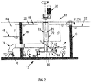
- a second liquid mixing and pumping system in accordance with the invention, is designated generally by the reference numeral 88.
- the liquid mixing and pumping system 88 includes certain features of the liquid mixing and pumping system 10 of Figure 1 . Corresponding features generally are again designated by the same reference numerals as before and are not described again.
- the liquid mixing and pumping system 88 includes a third reservoir 64, separated from the first reservoir 20 by the wall 16.
- the rotor 24 of the liquid mixing and pumping system 88 includes a mixer 68 identical to the mixer 28 of Figure 1 , except that it also has an arrangement of vanes 70 on top of the vane carrier plate 42. Alternatively, the lower vanes of the mixer 68 may be smaller than those of the mixer 28.
- the liquid mixing and pumping system 88 includes also:
- a vertical gap 80 is defined between the vanes 70 and the hood 74.
- the reservoir 64 contains liquid 46 up to a level as shown, Y2 below the liquid level in the reservoir 20.
- the drive mechanism 32 is activated to drive the rotor 24 at a speed suitable for the required mixing of liquid in the reservoir 20, typically a rotational speed below 200rpm. Centrifugal forces create an increased pressure zone 84 peripherally around the vanes 70 of the mixer 68 and a reduced pressure zone in the sleeve 72, causing the liquid level in the sleeve 72 to drop to a level as shown, Y3 below the liquid level in the reservoir 20.
- the liquid level in the reservoir 64 is higher than the liquid level in the sleeve 72, i.e. Y3 > Y2.
- a concomitant pressure head between the inlet 78 of the pipe 76 and the inside of the sleeve 72 induces liquid flow through the pipe 76, as indicated by the arrows 86, at a flow rate Qt2. Such flow exits the liquid mixing and pumping system 88 through the gap 80 as well as through the top vanes 70.
- the main purpose of the liquid flow through the pipe 76 may be recycling/transfer.
- the bottom vanes 44 of the liquid mixing and pumping system 88 are much smaller than those of the liquid mixing and pumping system 10 of Figure 1 , as a primary function of the system 88 is pumping and a secondary function is mixing.
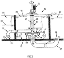
- a third liquid mixing and pumping system in accordance with the invention, is designated generally by the reference numeral 62.
- the liquid mixing and pumping system 62 includes certain features of the liquid mixing and pumping systems 10 and 88 of Figures 1 and 2 , respectively. Corresponding features generally are again designated by the same reference numerals as before and are not described again.
- the liquid mixing and pumping system 62 includes a third reservoir 64, separated from the first reservoir 20 by the wall 16.
- the rotor 24 of the liquid mixing and pumping system 62 includes a mixer 68 similar to the mixer 68 of the liquid mixing and pumping system 88 of Figure 2 , except that the bottom vanes 44 are larger and the top vanes 70 smaller than in the system 88.
- the drive mechanism 32 is activated to drive the rotor 24 at a speed suitable for the required mixing of liquid in the reservoir 20, typically a rotational speed below 200rpm.
- Liquid flow as indicated by the arrows 56 occurs in the pipe 34, as in the liquid mixing and pumping system 10 of Figure 1 .
- Centrifugal forces create an increased pressure zone 84 peripherally around the vanes 44, 70 of the mixer 68 and a reduced pressure zone in the sleeve 72, causing the liquid level in the sleeve 72 to drop to a level as shown, Y3 below the liquid level in the reservoir 20.
- the liquid level in the reservoir 20 is higher than the liquid level in the sleeve 72, i.e.
- the main purpose of the liquid flow through the pipe 34 is recycling in a waste water treatment process.
- the main purpose of the liquid flow through the pipe 76 is recycling/transfer at a higher head than the flow through the pipe 34.
- a waste water treatment process illustrated by a flow diagram, is designated generally by the reference numeral 90.
- the waste water treatment process 90 is an activated sludge process.
- the waste water treatment process 90 is implemented by means of the waste water treatment works 92, in accordance with the invention, which is shown in plan view in Figure 4b and in part sectional elevation in Figure 4c .
- the waste water treatment works 92 includes the following reservoirs:
- the waste water treatment works 92 includes also an arrangement of liquid transfer lines and liquid mixing and pumping systems, in accordance with the invention, for effecting mixing and pumping of liquid in the plant 92.
- These liquid mixing and pumping systems include liquid mixing and pumping systems 10.1 and 88.1.
- the liquid mixing and pumping system 10.1 is similar to the liquid mixing and pumping system 10 of Figure 1 .
- Corresponding features generally are again designated by the same reference numerals as before and are not described again.
- liquid mixing and pumping system 10.1 serves to:
- the configuration of the waste water treatment works 92 is such that, in use, liquid is transferred by overflow from the denitrification reactor 102 to the anaerobic reactor 94 and then to the anoxic reactor 96 due to the liquid level being higher in the denitrification reactor 102 than that in the anaerobic reactor 94 and the liquid level in the anaerobic reactor 94 being higher than that in the anoxic reactor 96.
- a certain proportion of the liquid is required to be recycled from the aerobic reactor 98, in which aeration occurred, to the anoxic reactor 96, in which no oxygen is present.
- This is achieved by means of the liquid mixing and pumping system 10.1, which effects such transfer through the transfer pipe 34, which is also referred to as "a Recycle" in the activated sludge process.
- Such recycling would conventionally have been done using a conventional pump.
- the use of the liquid mixing and pumping system 10.1 for both mixing and transfer of liquid therefore eliminates the use of such a conventional pump.
- the plant 90 includes also a raw sewage reservoir 104, in which the liquid mixing and pumping system 88.1 is installed.
- the liquid mixing and pumping system 88.1 serves to effect:
- the liquid mixing and pumping system 88.1 is similar to the liquid mixing and pumping system 88 of Figure 2 .
- Corresponding features generally are again designated by the same reference numerals as before and are not described again.
- the mixing and pumping system 88.1 includes an inlet pipe 76, a sleeve 72 (see Figure 2 ), and a hood 74 (see Figure 2 ).
- the pipe 76 transports raw sewage into the plant 92. Due to a reduced liquid level created in the sleeve 72 by operation of the mixer of the mixing and pumping system 88.1, as discussed above, liquid can be gravitated along the pipe 76 from a source with a lower liquid level than the reservoir 104.
- the liquid is then gravitated along the pipe 106 to the inlet chamber 108 under a pressure head resulting from a liquid level difference Y1 between the reservoir 104 and the chamber 108.
- the mixing and pumping system 88.1 also serves as a mixer in the reservoir 104.
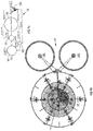
- a flow diagram of a waste water treatment process is designated generally by the reference numeral 110.
- the waste water treatment process 110 is an activated sludge process.
- the waste water treatment process 110 is implemented by means of the waste water treatment works 112, which is shown in plan view in Figure 5b and in part sectional elevation in Figure 5c .
- the waste water treatment works 112 includes the following reservoirs:
- the waste water treatment works 112 includes also an arrangement of liquid transfer lines and liquid mixing and pumping systems, in accordance with the invention, for effecting mixing and pumping of liquid in the plant 112.
- These liquid mixing and pumping systems include a liquid mixing and pumping system 62.1.
- the liquid mixing and pumping system 62.1 is similar to the liquid mixing and pumping system 62 of Figure 3 .
- Corresponding features generally are again designated by the same reference numerals as before and are not described again.
- the liquid mixing and pumping system 62.1 serves for effecting:
- the mixing and pumping system 62.1 therefore eliminates the requirement of a conventional pump for effecting the pumping.
- Waste liquid overflows to the denitrification reactor 102 due to the liquid level in the anaerobic reactor 94 being higher than that in the denitrification reactor 102. This is due to the waste water being transferred into the anaerobic reactor 94 through the pipes 34 and 76.
- the waste water in the denitrification reactor 102 is easily recycled back into the anaerobic reactor 94. This recycling occurs through the pipe 34.
- the configuration of the waste water treatment works 92 is such that, in use, liquid is transferred by overflow from the denitrification reactor 102 to the anaerobic reactor 94 and then to the anoxic reactor 96 due to the liquid level being higher in the denitrification reactor 102 than that in the anaerobic reactor 94 and the liquid level in the anaerobic reactor 94 being higher than that in the anoxic reactor 96.
- a certain proportion of the liquid is required to be recycled from the aerobic reactor 98, in which aeration occurred, to the anoxic reactor 96, in which no oxygen is present.
- This is achieved by means of the liquid mixing and pumping system 10.1, which effects such transfer through the transfer pipe 34, which is also referred to as "a Recycle" in the activated sludge process.
- Such recycling would conventionally have been done using a conventional pump.
- the use of the liquid mixing and pumping system 10.1 for both mixing and pumping of liquid therefore eliminates the use of such a conventional pump.
Landscapes
- Chemical & Material Sciences (AREA)
- Chemical Kinetics & Catalysis (AREA)
- Life Sciences & Earth Sciences (AREA)
- Microbiology (AREA)
- Biodiversity & Conservation Biology (AREA)
- Hydrology & Water Resources (AREA)
- Engineering & Computer Science (AREA)
- Environmental & Geological Engineering (AREA)
- Water Supply & Treatment (AREA)
- Organic Chemistry (AREA)
- Mixers Of The Rotary Stirring Type (AREA)
Claims (8)
- Station de traitement des eaux usées (92) comprenant :un système de mélange et de pompage de liquide (88) pour un premier réservoir (20, 102) contenant du liquide (46) de manière fonctionnelle, le système (88) comprenant :un premier mélangeur (68), submergé de manière fonctionnelle dans le liquide (46) contenu dans le premier réservoir (20, 102) et en mesure de tourner autour d'un axe de rotation vertical (30), le mélangeur (68) comprenant un agencement de pales (44, 70) agencées dans le sens périphérique autour de l'axe de rotation (30) et étant espacées par rapport à tous les côtés du premier réservoir (20, 102) ;un plateau porteur de pales disposé à l'horizontale (42) ;un moyen d'entraînement (32) servant à faire tourner le mélangeur (68) de manière fonctionnelle quand il est submergé dans le liquide (46) pour induire au niveau du mélangeur (68) une zone de pression réduite autour de l'axe de rotation (30) en-dessous et au-dessus du mélangeur (68) et pour induire, dans le sens périphérique autour des pales (44, 70), une zone de pression accrue (84) donnant lieu à un flux du liquide (46) allant vers l'extérieur dans le sens périphérique à l'opposé du mélangeur (68) ;un arbre vertical (26) pour le mélangeur (68), s'étendant vers le haut depuis le mélangeur (68) ;une gaine verticale (72) disposée autour de l'arbre vertical (26), la gaine (72) définissant une extrémité supérieure se trouvant de manière fonctionnelle au-dessus d'une surface du liquide (46) dans le premier réservoir (20, 102) et une extrémité inférieure se trouvant de manière fonctionnelle en-dessous de la surface du liquide (46) et au-dessus du mélangeur (68) ; etun tuyau de transfert supérieur (76) ayant une sortie en communication avec un passage défini dans la gaine (72), la sortie étant à un niveau se trouvant de manière fonctionnelle en-dessous de la surface du liquide (46) dans le premier réservoir (20, 102), dans une configuration dans laquelle, en cours de fonctionnement, le flux du liquide allant vers l'extérieur à l'opposé du mélangeur (68) donne lieu à la zone de pression réduite qui, à son tour, donne lieu à la chute du niveau de liquide (Y3) dans la gaine (72) ;un deuxième réservoir (64), le tuyau de transfert supérieur (76) ayant son entrée (78) dans le deuxième réservoir (64) et servant à transférer du liquide en provenance du deuxième réservoir (64) jusqu'au premier réservoir (20, 102),caractérisée en ce que:l'agencement de pales (44, 70) du mélangeur (68) comprend un agencement supérieur de pales (70) se tenant à la verticale en saillie par rapport au plateau porteur de pales (42) et un agencement inférieur de pales (44) dépendant du plateau porteur de pales (42) ;un capot (74) est mis en oeuvre au niveau de l'extrémité inférieure de la gaine (72), disposé sur le mélangeur (68) avec un espace vertical (80) défini entre le capot (74) et l'agencement supérieur de pales (70), pour empêcher un vortex, pouvant se former de manière fonctionnelle dans la gaine (72), d'atteindre le mélangeur (68) et de venir gêner son fonctionnement ; etdes forces centrifuges créent une zone de pression accrue (84) dans le sens périphérique autour des pales (44, 70) du mélangeur (68) et une zone de pression réduite dans la gaine (72), ceci donnant lieu à la chute du niveau de liquide (Y3) dans la gaine (72) en-dessous d'un niveau de liquide (Y2) dans le premier réservoir (20, 102), une charge de pression simultanée entre l'entrée (78) du tuyau de transfert supérieur (76) et une partie intérieure de la gaine (72) induit un flux de liquide (86) au travers du tuyau de transfert supérieur (76), à un débit (Qt2), liquide qui s'écoule (86) au travers de l'espace (80) ainsi qu'au travers des pales supérieures (70).
- Station de traitement (92) selon la revendication 1, dans laquelle la vitesse de rotation du mélangeur (68) est ajustable, pour ainsi faire varier le débit et une éventuelle charge générée au travers du tuyau de transfert supérieur (76).
- Station de traitement (92) selon la revendication 1 ou la revendication 2, dans laquelle le moyen d'entraînement (32) sert à faire tourner le rotor (24) à une vitesse de rotation inférieure à 200 tr/min.
- Station de traitement (92) selon l'une quelconque des revendications précédentes, qui comprend aussi au moins un deuxième mélangeur, les mélangeurs étant de différentes tailles et étant interchangeables pour faire varier le débit et l'éventuelle charge générée au travers du tuyau de transfert supérieur (76).
- Station de traitement (92) selon l'une quelconque des revendications précédentes, dans laquelle le premier réservoir (20, 102) est un réacteur anoxique (96).
- Station de traitement (92) selon la revendication 5, dans laquelle le deuxième réservoir (64) est un réacteur anaérobie (94), le tuyau de transfert supérieur (76) servant à transférer du liquide en provenance du réacteur anaérobie (94) jusqu'au réacteur anoxique (96).
- Station de traitement selon l'une quelconque des revendications 1 à 4, dans laquelle:le premier réservoir (20, 102) est un réacteur anaérobie (94) ; etle deuxième réservoir (64) est une chambre d'entrée de matières brutes (108), le tuyau de transfert supérieur (76) servant à transférer du liquide en provenance de la chambre d'entrée de matières brutes (108) jusqu'au réacteur anaérobie (94).
- Station de traitement (92) selon l'une quelconque des revendications précédentes, dans laquelle le liquide transféré en provenance du deuxième réservoir (64) jusqu'au premier réservoir (20, 102) est ensuite mélangé (M) dans le premier réservoir (20, 102) par le premier mélangeur (68).
Priority Applications (1)
| Application Number | Priority Date | Filing Date | Title |
|---|---|---|---|
| EP17196707.8A EP3308849A1 (fr) | 2010-03-03 | 2011-03-03 | Système de traitement des eaux usées |
Applications Claiming Priority (2)
| Application Number | Priority Date | Filing Date | Title |
|---|---|---|---|
| ZA201001553 | 2010-03-03 | ||
| EP20110715610 EP2542333B1 (fr) | 2010-03-03 | 2011-03-03 | Dispositif de traitement des eaux usées |
Related Parent Applications (1)
| Application Number | Title | Priority Date | Filing Date |
|---|---|---|---|
| EP20110715610 Division EP2542333B1 (fr) | 2010-03-03 | 2011-03-03 | Dispositif de traitement des eaux usées |
Related Child Applications (1)
| Application Number | Title | Priority Date | Filing Date |
|---|---|---|---|
| EP17196707.8A Division EP3308849A1 (fr) | 2010-03-03 | 2011-03-03 | Système de traitement des eaux usées |
Publications (2)
| Publication Number | Publication Date |
|---|---|
| EP2826548A1 EP2826548A1 (fr) | 2015-01-21 |
| EP2826548B1 true EP2826548B1 (fr) | 2017-10-18 |
Family
ID=44065631
Family Applications (3)
| Application Number | Title | Priority Date | Filing Date |
|---|---|---|---|
| EP20110715610 Not-in-force EP2542333B1 (fr) | 2010-03-03 | 2011-03-03 | Dispositif de traitement des eaux usées |
| EP14181999.5A Not-in-force EP2826548B1 (fr) | 2010-03-03 | 2011-03-03 | Système de traitement des eaux usées |
| EP17196707.8A Withdrawn EP3308849A1 (fr) | 2010-03-03 | 2011-03-03 | Système de traitement des eaux usées |
Family Applications Before (1)
| Application Number | Title | Priority Date | Filing Date |
|---|---|---|---|
| EP20110715610 Not-in-force EP2542333B1 (fr) | 2010-03-03 | 2011-03-03 | Dispositif de traitement des eaux usées |
Family Applications After (1)
| Application Number | Title | Priority Date | Filing Date |
|---|---|---|---|
| EP17196707.8A Withdrawn EP3308849A1 (fr) | 2010-03-03 | 2011-03-03 | Système de traitement des eaux usées |
Country Status (9)
| Country | Link |
|---|---|
| US (1) | US20130056400A1 (fr) |
| EP (3) | EP2542333B1 (fr) |
| BR (1) | BR112012022233B1 (fr) |
| DK (2) | DK2826548T3 (fr) |
| ES (2) | ES2655717T3 (fr) |
| NO (1) | NO2826548T3 (fr) |
| PT (2) | PT2542333E (fr) |
| WO (1) | WO2011107959A1 (fr) |
| ZA (1) | ZA201101736B (fr) |
Families Citing this family (4)
| Publication number | Priority date | Publication date | Assignee | Title |
|---|---|---|---|---|
| CN104162400B (zh) * | 2013-05-20 | 2016-05-11 | 宁波凯诚环保科技有限公司 | 水洗反应釜及水洗反应方法 |
| CN104174348B (zh) * | 2013-05-20 | 2017-07-21 | 宁波凯诚环保科技有限公司 | 中和反应釜及中和反应方法 |
| CN106865769B (zh) * | 2017-03-27 | 2020-10-02 | 青岛理工大学 | 高浓度有机废水净化装置及净化方法 |
| RU199676U1 (ru) * | 2020-06-19 | 2020-09-14 | Общество с ограниченной ответственностью "Научно-производственное объединение Автоматика" | Смеситель |
Citations (1)
| Publication number | Priority date | Publication date | Assignee | Title |
|---|---|---|---|---|
| US3984001A (en) * | 1974-03-25 | 1976-10-05 | Mitsui Mining & Smelting Co., Ltd. | Bubble-dispersing apparatus |
Family Cites Families (18)
| Publication number | Priority date | Publication date | Assignee | Title |
|---|---|---|---|---|
| US1947851A (en) * | 1930-01-31 | 1934-02-20 | Nat Aniline & Chem Co Inc | Mixing apparatus |
| US2090384A (en) * | 1935-12-18 | 1937-08-17 | Chicago Pump Co | Sewage treatment apparatus |
| US3053390A (en) * | 1957-04-24 | 1962-09-11 | Fred J Wood | Sewage treating apparatus |
| US2987186A (en) | 1957-11-21 | 1961-06-06 | Yeomans Brothers Co | Apparatus for treating waste materials |
| US3207314A (en) * | 1961-10-30 | 1965-09-21 | Chester H Pearson | Sewage treatment apparatus |
| US3661261A (en) * | 1970-12-31 | 1972-05-09 | Fmc Corp | Method and apparatus for flushing sewers |
| US3954606A (en) * | 1973-11-12 | 1976-05-04 | Air Products And Chemicals, Inc. | Wastewater treatment system with controlled mixing |
| NL8101294A (nl) * | 1981-03-17 | 1982-10-18 | Tno | Roerder met naar de omtrek oplopende hoofdzakelijk driehoekige, radiale bladen. |
| US5525269A (en) * | 1985-03-22 | 1996-06-11 | Philadelphia Gear Corporation | Impeller tiplets for improving gas to liquid mass transfer efficiency in a draft tube submerged turbine mixer/aerator |
| US4664795A (en) * | 1985-03-25 | 1987-05-12 | William A. Stegall | Two-stage waste water treatment system for single family residences and the like |
| US5110464A (en) * | 1988-09-30 | 1992-05-05 | Vladimir Etlin | Apparatus for recirculation of liquids |
| US5264130A (en) * | 1988-09-30 | 1993-11-23 | Vladimir Etlin | Method and apparatus for recirculation of liquids |
| CZ282411B6 (cs) * | 1994-12-02 | 1997-07-16 | Jan Ing. Topol | Čištění odpadních vod kombinací kontinuálního a diskontinuálního průtoku |
| US5569376A (en) * | 1995-03-06 | 1996-10-29 | Norwalk Wastewater Equipment Company | Flow augmenting devices for a wastewater treatment plant |
| DE29604168U1 (de) * | 1996-03-06 | 1996-06-05 | Schmalenberger GmbH & Co, 72072 Tübingen | Einrichtung zum Umwälzen von verunreinigten Flüssigkeiten |
| US6997444B2 (en) * | 2003-04-29 | 2006-02-14 | Spx Corporation | Radial disc impeller apparatus and method |
| WO2005093261A2 (fr) * | 2003-12-10 | 2005-10-06 | Zacharias Joseph Van Den Berg | Equipement de transfert de liquide a volume eleve et a basse pression fonctionnant en immersion |
| US20060175252A1 (en) * | 2005-02-04 | 2006-08-10 | Upendrakumar K C | Two phase anaerobic contact sequencing batch reactor (ACSBR) system for treating wastewater containing simple and complex organic constituents |
-
2011
- 2011-03-03 ES ES14181999.5T patent/ES2655717T3/es active Active
- 2011-03-03 EP EP20110715610 patent/EP2542333B1/fr not_active Not-in-force
- 2011-03-03 DK DK14181999.5T patent/DK2826548T3/en active
- 2011-03-03 EP EP14181999.5A patent/EP2826548B1/fr not_active Not-in-force
- 2011-03-03 WO PCT/IB2011/050912 patent/WO2011107959A1/fr not_active Ceased
- 2011-03-03 PT PT117156109T patent/PT2542333E/pt unknown
- 2011-03-03 BR BR112012022233A patent/BR112012022233B1/pt not_active IP Right Cessation
- 2011-03-03 ES ES11715610.9T patent/ES2524728T3/es active Active
- 2011-03-03 PT PT141819995T patent/PT2826548T/pt unknown
- 2011-03-03 US US13/582,258 patent/US20130056400A1/en not_active Abandoned
- 2011-03-03 DK DK11715610.9T patent/DK2542333T3/en active
- 2011-03-03 NO NO14181999A patent/NO2826548T3/no unknown
- 2011-03-03 EP EP17196707.8A patent/EP3308849A1/fr not_active Withdrawn
- 2011-03-07 ZA ZA2011/01736A patent/ZA201101736B/en unknown
Patent Citations (1)
| Publication number | Priority date | Publication date | Assignee | Title |
|---|---|---|---|---|
| US3984001A (en) * | 1974-03-25 | 1976-10-05 | Mitsui Mining & Smelting Co., Ltd. | Bubble-dispersing apparatus |
Also Published As
| Publication number | Publication date |
|---|---|
| EP2542333B1 (fr) | 2014-08-27 |
| ES2524728T3 (es) | 2014-12-11 |
| ZA201101736B (en) | 2013-02-27 |
| BR112012022233B1 (pt) | 2019-12-03 |
| WO2011107959A1 (fr) | 2011-09-09 |
| EP2826548A1 (fr) | 2015-01-21 |
| PT2826548T (pt) | 2018-01-12 |
| BR112012022233A2 (pt) | 2016-07-05 |
| DK2542333T3 (en) | 2014-12-08 |
| NO2826548T3 (fr) | 2018-03-17 |
| EP2542333A1 (fr) | 2013-01-09 |
| ES2655717T3 (es) | 2018-02-21 |
| EP3308849A1 (fr) | 2018-04-18 |
| DK2826548T3 (en) | 2018-01-22 |
| US20130056400A1 (en) | 2013-03-07 |
| PT2542333E (pt) | 2014-12-03 |
Similar Documents
| Publication | Publication Date | Title |
|---|---|---|
| KR101587265B1 (ko) | 슬러지 교반 및 건조장치 | |
| CN100503052C (zh) | 絮凝处理方法、反应器及流体处理设备 | |
| KR200455119Y1 (ko) | 탱크내 저장유체의 교반장치 | |
| CZ297858B6 (cs) | Zarízení pro míchání a provzdusnování kapaliny a pro eliminaci peny uvnitr nádrze pri zpracování této kapaliny | |
| EP2542333B1 (fr) | Dispositif de traitement des eaux usées | |
| KR100512089B1 (ko) | 고속 고효율 폭기장치 | |
| CN201309852Y (zh) | 一种污水净化沉淀器 | |
| JP5493662B2 (ja) | 流動床式生物処理装置 | |
| CN104341021A (zh) | 序进式气浮装置 | |
| JP2008296169A (ja) | 曝気攪拌システムの運転方法 | |
| US7967498B2 (en) | Submersibly operable high volume and low pressure liquid transfer equipment | |
| JP2010167328A (ja) | 曝気攪拌機 | |
| CN207016548U (zh) | 一种带搅拌的曝气池装置 | |
| US3951758A (en) | Method of operating a purifying plant and tank for practicing said method | |
| KR101745837B1 (ko) | 생물학적 처리 장치용 무동력 교반기 | |
| JP2007229600A (ja) | 汚泥処理システム | |
| KR102195868B1 (ko) | 단일 반응조형 가압부상 시스템 | |
| KR102005018B1 (ko) | 무동력 교반기를 이용한 생물학적 처리 장치 | |
| JP3645423B2 (ja) | 水中攪拌曝気装置 | |
| KR102479538B1 (ko) | 폐수 처리용 교반기 | |
| CN114314748B (zh) | 污水处理反应器 | |
| CS216658B2 (en) | Method of flotation cleaning of liquids and device for executing the said method | |
| KR100768571B1 (ko) | 하수처리 탈인조 | |
| JP4813414B2 (ja) | 水槽内対流惹起装置 | |
| JP7134947B2 (ja) | 撹拌装置及び水処理システム |
Legal Events
| Date | Code | Title | Description |
|---|---|---|---|
| 17P | Request for examination filed |
Effective date: 20140822 |
|
| AC | Divisional application: reference to earlier application |
Ref document number: 2542333 Country of ref document: EP Kind code of ref document: P |
|
| AK | Designated contracting states |
Kind code of ref document: A1 Designated state(s): AL AT BE BG CH CY CZ DE DK EE ES FI FR GB GR HR HU IE IS IT LI LT LU LV MC MK MT NL NO PL PT RO RS SE SI SK SM TR |
|
| PUAI | Public reference made under article 153(3) epc to a published international application that has entered the european phase |
Free format text: ORIGINAL CODE: 0009012 |
|
| R17P | Request for examination filed (corrected) |
Effective date: 20150721 |
|
| RBV | Designated contracting states (corrected) |
Designated state(s): AL AT BE BG CH CY CZ DE DK EE ES FI FR GB GR HR HU IE IS IT LI LT LU LV MC MK MT NL NO PL PT RO RS SE SI SK SM TR |
|
| 17Q | First examination report despatched |
Effective date: 20160115 |
|
| GRAP | Despatch of communication of intention to grant a patent |
Free format text: ORIGINAL CODE: EPIDOSNIGR1 |
|
| RIC1 | Information provided on ipc code assigned before grant |
Ipc: B01F 7/16 20060101ALI20170420BHEP Ipc: B01F 5/10 20060101AFI20170420BHEP Ipc: C02F 3/28 20060101ALI20170420BHEP Ipc: C02F 3/12 20060101ALI20170420BHEP Ipc: B01F 15/00 20060101ALN20170420BHEP Ipc: B01F 13/10 20060101ALI20170420BHEP Ipc: B01F 3/12 20060101ALN20170420BHEP |
|
| INTG | Intention to grant announced |
Effective date: 20170516 |
|
| GRAS | Grant fee paid |
Free format text: ORIGINAL CODE: EPIDOSNIGR3 |
|
| GRAA | (expected) grant |
Free format text: ORIGINAL CODE: 0009210 |
|
| AC | Divisional application: reference to earlier application |
Ref document number: 2542333 Country of ref document: EP Kind code of ref document: P |
|
| AK | Designated contracting states |
Kind code of ref document: B1 Designated state(s): AL AT BE BG CH CY CZ DE DK EE ES FI FR GB GR HR HU IE IS IT LI LT LU LV MC MK MT NL NO PL PT RO RS SE SI SK SM TR |
|
| REG | Reference to a national code |
Ref country code: GB Ref legal event code: FG4D |
|
| REG | Reference to a national code |
Ref country code: CH Ref legal event code: EP |
|
| REG | Reference to a national code |
Ref country code: AT Ref legal event code: REF Ref document number: 937460 Country of ref document: AT Kind code of ref document: T Effective date: 20171115 Ref country code: IE Ref legal event code: FG4D |
|
| REG | Reference to a national code |
Ref country code: DE Ref legal event code: R096 Ref document number: 602011042609 Country of ref document: DE |
|
| REG | Reference to a national code |
Ref country code: PT Ref legal event code: SC4A Ref document number: 2826548 Country of ref document: PT Date of ref document: 20180112 Kind code of ref document: T Free format text: AVAILABILITY OF NATIONAL TRANSLATION Effective date: 20180104 |
|
| REG | Reference to a national code |
Ref country code: FR Ref legal event code: PLFP Year of fee payment: 8 |
|
| REG | Reference to a national code |
Ref country code: DK Ref legal event code: T3 Effective date: 20180115 |
|
| REG | Reference to a national code |
Ref country code: NL Ref legal event code: FP |
|
| REG | Reference to a national code |
Ref country code: SE Ref legal event code: TRGR |
|
| REG | Reference to a national code |
Ref country code: ES Ref legal event code: FG2A Ref document number: 2655717 Country of ref document: ES Kind code of ref document: T3 Effective date: 20180221 |
|
| REG | Reference to a national code |
Ref country code: LT Ref legal event code: MG4D Ref country code: NO Ref legal event code: T2 Effective date: 20171018 |
|
| REG | Reference to a national code |
Ref country code: AT Ref legal event code: MK05 Ref document number: 937460 Country of ref document: AT Kind code of ref document: T Effective date: 20171018 |
|
| PG25 | Lapsed in a contracting state [announced via postgrant information from national office to epo] |
Ref country code: LT Free format text: LAPSE BECAUSE OF FAILURE TO SUBMIT A TRANSLATION OF THE DESCRIPTION OR TO PAY THE FEE WITHIN THE PRESCRIBED TIME-LIMIT Effective date: 20171018 Ref country code: FI Free format text: LAPSE BECAUSE OF FAILURE TO SUBMIT A TRANSLATION OF THE DESCRIPTION OR TO PAY THE FEE WITHIN THE PRESCRIBED TIME-LIMIT Effective date: 20171018 |
|
| PG25 | Lapsed in a contracting state [announced via postgrant information from national office to epo] |
Ref country code: RS Free format text: LAPSE BECAUSE OF FAILURE TO SUBMIT A TRANSLATION OF THE DESCRIPTION OR TO PAY THE FEE WITHIN THE PRESCRIBED TIME-LIMIT Effective date: 20171018 Ref country code: AT Free format text: LAPSE BECAUSE OF FAILURE TO SUBMIT A TRANSLATION OF THE DESCRIPTION OR TO PAY THE FEE WITHIN THE PRESCRIBED TIME-LIMIT Effective date: 20171018 Ref country code: BG Free format text: LAPSE BECAUSE OF FAILURE TO SUBMIT A TRANSLATION OF THE DESCRIPTION OR TO PAY THE FEE WITHIN THE PRESCRIBED TIME-LIMIT Effective date: 20180118 Ref country code: GR Free format text: LAPSE BECAUSE OF FAILURE TO SUBMIT A TRANSLATION OF THE DESCRIPTION OR TO PAY THE FEE WITHIN THE PRESCRIBED TIME-LIMIT Effective date: 20180119 Ref country code: IS Free format text: LAPSE BECAUSE OF FAILURE TO SUBMIT A TRANSLATION OF THE DESCRIPTION OR TO PAY THE FEE WITHIN THE PRESCRIBED TIME-LIMIT Effective date: 20180218 Ref country code: LV Free format text: LAPSE BECAUSE OF FAILURE TO SUBMIT A TRANSLATION OF THE DESCRIPTION OR TO PAY THE FEE WITHIN THE PRESCRIBED TIME-LIMIT Effective date: 20171018 Ref country code: HR Free format text: LAPSE BECAUSE OF FAILURE TO SUBMIT A TRANSLATION OF THE DESCRIPTION OR TO PAY THE FEE WITHIN THE PRESCRIBED TIME-LIMIT Effective date: 20171018 |
|
| REG | Reference to a national code |
Ref country code: DE Ref legal event code: R097 Ref document number: 602011042609 Country of ref document: DE |
|
| PG25 | Lapsed in a contracting state [announced via postgrant information from national office to epo] |
Ref country code: SK Free format text: LAPSE BECAUSE OF FAILURE TO SUBMIT A TRANSLATION OF THE DESCRIPTION OR TO PAY THE FEE WITHIN THE PRESCRIBED TIME-LIMIT Effective date: 20171018 Ref country code: CZ Free format text: LAPSE BECAUSE OF FAILURE TO SUBMIT A TRANSLATION OF THE DESCRIPTION OR TO PAY THE FEE WITHIN THE PRESCRIBED TIME-LIMIT Effective date: 20171018 Ref country code: EE Free format text: LAPSE BECAUSE OF FAILURE TO SUBMIT A TRANSLATION OF THE DESCRIPTION OR TO PAY THE FEE WITHIN THE PRESCRIBED TIME-LIMIT Effective date: 20171018 |
|
| PLBE | No opposition filed within time limit |
Free format text: ORIGINAL CODE: 0009261 |
|
| STAA | Information on the status of an ep patent application or granted ep patent |
Free format text: STATUS: NO OPPOSITION FILED WITHIN TIME LIMIT |
|
| PG25 | Lapsed in a contracting state [announced via postgrant information from national office to epo] |
Ref country code: RO Free format text: LAPSE BECAUSE OF FAILURE TO SUBMIT A TRANSLATION OF THE DESCRIPTION OR TO PAY THE FEE WITHIN THE PRESCRIBED TIME-LIMIT Effective date: 20171018 Ref country code: PL Free format text: LAPSE BECAUSE OF FAILURE TO SUBMIT A TRANSLATION OF THE DESCRIPTION OR TO PAY THE FEE WITHIN THE PRESCRIBED TIME-LIMIT Effective date: 20171018 Ref country code: SM Free format text: LAPSE BECAUSE OF FAILURE TO SUBMIT A TRANSLATION OF THE DESCRIPTION OR TO PAY THE FEE WITHIN THE PRESCRIBED TIME-LIMIT Effective date: 20171018 |
|
| 26N | No opposition filed |
Effective date: 20180719 |
|
| REG | Reference to a national code |
Ref country code: CH Ref legal event code: PL |
|
| PG25 | Lapsed in a contracting state [announced via postgrant information from national office to epo] |
Ref country code: MC Free format text: LAPSE BECAUSE OF FAILURE TO SUBMIT A TRANSLATION OF THE DESCRIPTION OR TO PAY THE FEE WITHIN THE PRESCRIBED TIME-LIMIT Effective date: 20171018 Ref country code: SI Free format text: LAPSE BECAUSE OF FAILURE TO SUBMIT A TRANSLATION OF THE DESCRIPTION OR TO PAY THE FEE WITHIN THE PRESCRIBED TIME-LIMIT Effective date: 20171018 |
|
| PG25 | Lapsed in a contracting state [announced via postgrant information from national office to epo] |
Ref country code: LU Free format text: LAPSE BECAUSE OF NON-PAYMENT OF DUE FEES Effective date: 20180303 |
|
| PG25 | Lapsed in a contracting state [announced via postgrant information from national office to epo] |
Ref country code: LI Free format text: LAPSE BECAUSE OF NON-PAYMENT OF DUE FEES Effective date: 20180331 Ref country code: CH Free format text: LAPSE BECAUSE OF NON-PAYMENT OF DUE FEES Effective date: 20180331 |
|
| PG25 | Lapsed in a contracting state [announced via postgrant information from national office to epo] |
Ref country code: MT Free format text: LAPSE BECAUSE OF NON-PAYMENT OF DUE FEES Effective date: 20180303 |
|
| PGFP | Annual fee paid to national office [announced via postgrant information from national office to epo] |
Ref country code: IT Payment date: 20200221 Year of fee payment: 10 Ref country code: DK Payment date: 20200310 Year of fee payment: 10 Ref country code: NO Payment date: 20200310 Year of fee payment: 10 Ref country code: GB Payment date: 20200219 Year of fee payment: 10 Ref country code: IE Payment date: 20200309 Year of fee payment: 10 Ref country code: SE Payment date: 20200310 Year of fee payment: 10 Ref country code: NL Payment date: 20200212 Year of fee payment: 10 Ref country code: PT Payment date: 20200303 Year of fee payment: 10 Ref country code: DE Payment date: 20200218 Year of fee payment: 10 |
|
| PG25 | Lapsed in a contracting state [announced via postgrant information from national office to epo] |
Ref country code: HU Free format text: LAPSE BECAUSE OF FAILURE TO SUBMIT A TRANSLATION OF THE DESCRIPTION OR TO PAY THE FEE WITHIN THE PRESCRIBED TIME-LIMIT; INVALID AB INITIO Effective date: 20110303 |
|
| PGFP | Annual fee paid to national office [announced via postgrant information from national office to epo] |
Ref country code: BE Payment date: 20200217 Year of fee payment: 10 |
|
| PG25 | Lapsed in a contracting state [announced via postgrant information from national office to epo] |
Ref country code: CY Free format text: LAPSE BECAUSE OF FAILURE TO SUBMIT A TRANSLATION OF THE DESCRIPTION OR TO PAY THE FEE WITHIN THE PRESCRIBED TIME-LIMIT Effective date: 20171018 Ref country code: MK Free format text: LAPSE BECAUSE OF NON-PAYMENT OF DUE FEES Effective date: 20171018 |
|
| PGFP | Annual fee paid to national office [announced via postgrant information from national office to epo] |
Ref country code: TR Payment date: 20200303 Year of fee payment: 10 Ref country code: FR Payment date: 20200113 Year of fee payment: 10 |
|
| PG25 | Lapsed in a contracting state [announced via postgrant information from national office to epo] |
Ref country code: AL Free format text: LAPSE BECAUSE OF FAILURE TO SUBMIT A TRANSLATION OF THE DESCRIPTION OR TO PAY THE FEE WITHIN THE PRESCRIBED TIME-LIMIT Effective date: 20171018 |
|
| PGFP | Annual fee paid to national office [announced via postgrant information from national office to epo] |
Ref country code: ES Payment date: 20200401 Year of fee payment: 10 |
|
| REG | Reference to a national code |
Ref country code: DE Ref legal event code: R119 Ref document number: 602011042609 Country of ref document: DE |
|
| REG | Reference to a national code |
Ref country code: NO Ref legal event code: MMEP |
|
| REG | Reference to a national code |
Ref country code: DK Ref legal event code: EBP Effective date: 20210331 |
|
| REG | Reference to a national code |
Ref country code: NL Ref legal event code: MM Effective date: 20210401 |
|
| GBPC | Gb: european patent ceased through non-payment of renewal fee |
Effective date: 20210303 |
|
| PG25 | Lapsed in a contracting state [announced via postgrant information from national office to epo] |
Ref country code: PT Free format text: LAPSE BECAUSE OF NON-PAYMENT OF DUE FEES Effective date: 20210903 |
|
| REG | Reference to a national code |
Ref country code: BE Ref legal event code: MM Effective date: 20210331 |
|
| PG25 | Lapsed in a contracting state [announced via postgrant information from national office to epo] |
Ref country code: NO Free format text: LAPSE BECAUSE OF NON-PAYMENT OF DUE FEES Effective date: 20210331 Ref country code: NL Free format text: LAPSE BECAUSE OF NON-PAYMENT OF DUE FEES Effective date: 20210401 Ref country code: FR Free format text: LAPSE BECAUSE OF NON-PAYMENT OF DUE FEES Effective date: 20210331 Ref country code: GB Free format text: LAPSE BECAUSE OF NON-PAYMENT OF DUE FEES Effective date: 20210303 Ref country code: IE Free format text: LAPSE BECAUSE OF NON-PAYMENT OF DUE FEES Effective date: 20210303 Ref country code: SE Free format text: LAPSE BECAUSE OF NON-PAYMENT OF DUE FEES Effective date: 20210304 Ref country code: DE Free format text: LAPSE BECAUSE OF NON-PAYMENT OF DUE FEES Effective date: 20211001 |
|
| PG25 | Lapsed in a contracting state [announced via postgrant information from national office to epo] |
Ref country code: IT Free format text: LAPSE BECAUSE OF NON-PAYMENT OF DUE FEES Effective date: 20210303 Ref country code: DK Free format text: LAPSE BECAUSE OF NON-PAYMENT OF DUE FEES Effective date: 20210331 |
|
| REG | Reference to a national code |
Ref country code: ES Ref legal event code: FD2A Effective date: 20220523 |
|
| PG25 | Lapsed in a contracting state [announced via postgrant information from national office to epo] |
Ref country code: ES Free format text: LAPSE BECAUSE OF NON-PAYMENT OF DUE FEES Effective date: 20210304 Ref country code: BE Free format text: LAPSE BECAUSE OF NON-PAYMENT OF DUE FEES Effective date: 20210331 |
|
| PG25 | Lapsed in a contracting state [announced via postgrant information from national office to epo] |
Ref country code: TR Free format text: LAPSE BECAUSE OF NON-PAYMENT OF DUE FEES Effective date: 20210303 |