EP2826593B1 - Composants et turbine de grenaillage - Google Patents
Composants et turbine de grenaillage Download PDFInfo
- Publication number
- EP2826593B1 EP2826593B1 EP13398011.0A EP13398011A EP2826593B1 EP 2826593 B1 EP2826593 B1 EP 2826593B1 EP 13398011 A EP13398011 A EP 13398011A EP 2826593 B1 EP2826593 B1 EP 2826593B1
- Authority
- EP
- European Patent Office
- Prior art keywords
- blade
- turbine
- impeller
- control cage
- lining
- Prior art date
- Legal status (The legal status is an assumption and is not a legal conclusion. Google has not performed a legal analysis and makes no representation as to the accuracy of the status listed.)
- Active
Links
Images




Classifications
-
- B—PERFORMING OPERATIONS; TRANSPORTING
- B24—GRINDING; POLISHING
- B24C—ABRASIVE OR RELATED BLASTING WITH PARTICULATE MATERIAL
- B24C5/00—Devices or accessories for generating abrasive blasts
- B24C5/06—Impeller wheels; Rotor blades therefor
- B24C5/068—Transferring the abrasive particles from the feeding means onto the propeller blades, e.g. using central impellers
-
- B—PERFORMING OPERATIONS; TRANSPORTING
- B24—GRINDING; POLISHING
- B24C—ABRASIVE OR RELATED BLASTING WITH PARTICULATE MATERIAL
- B24C5/00—Devices or accessories for generating abrasive blasts
- B24C5/06—Impeller wheels; Rotor blades therefor
- B24C5/062—Rotor blades or vanes; Locking means therefor
Definitions
- the present invention relates to a shot blasting turbine and components comprised in the same. It mainly refers to a shot blasting turbine to throw abrasive materials to a surface of a piece to be shot blasted, having said turbine at least two blades to direct the abrasive over the surface of the piece, said blade placed between two runner heads; an impeller that accelerates the abrasive towards the blade; and a control cage with an opening or window from which the abrasive leaves the impeller to the blade.
- the invention is preferably addressed to be used in the foundry industry, although it can be used in other industries.
- shot blasting turbine throws abrasives of different natures and sizes to a surface to be shot blasted.
- the propelling force (centrifugal force) is given by a quantity of metallic blades placed on a runner head (or 2) moved by an electric motor.
- the abrasive is fed into the blades by an impeller that accelerates the abrasive towards the blade surface, involved on the control cage that has an opening from which the abrasive leaves the impeller to the blade.
- the position of the opening of the control cage determines the direction of the flow of the abrasive, (see for example DE 101 04 703 C1 ).
- a variety of these main elements of a classical turbine can be found in the market. From straight blades to curved blades; casted or machined blades, with 1 or 2 Runner Heads; multiple sizes and diameters of runner heads; control Cages and impellers casted or machined, etc.
- abrasives suitable to be used on a shot blast turbines we can mention as examples: high and low carbon steel shot, steel grit, cast iron shot and grit, steel Cut Wire Pellets, Stainless Steel shot and grit, non-ferrous shot and grit (aluminium, bronze, zinc, etc.), plastic media, Glass Beads, etc.
- the shot blasting turbines can be used for different main objectives, for example:
- EP1354667A1 refers to a prior art shot blasting turbine.
- Foundry Industry represents the most important industry on the shot blasting technique applications. To give an idea of its importance in the global shot blasting industries, Foundry Industry is the largest consumer of metallic abrasives for shot blasting applications as it consumes over 25% of the total consumption of metallic abrasives in the global market. This represents the largest concentration of shot blasting turbines in one single industry and, consequently, an enormous quantity of shot blasting turbines in operation every minute of the year. Further, among the foundry industry, the automotive sector represents almost 70% of the total foundry industry consumption and therefore its importance in the shot blasting technique and the need to pay special attention to it.
- the amount of silica sand on the abrasive mix is a fact that despite all elimination systems, such as air current separators and magnetic separators, still persists in high or low degree depending on the performance and quality of maintenance of the equipment. It is a fact with which the turbines have to cope when in use on foundry applications. Moreover, on the automotive foundry industry, the working 24 over 24 hours per day, 6 days per week, and sometimes 7 days, 48 and more weeks per year, does not leave much time for frequent maintenance.
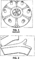
- Figure 1 shows this problem in a runner head while figure 2 show damages on a blade. Also while in use, such a degradation of the blade can cause imbalance on the turbine, with the consequent damaging on the motor bearings.
- the hard steel part is a cylinder with a rectangular or square opening, exit window, through which the abrasive leaves to the blades and which orientates the direction of the jet stream.
- the hard metal (tungsten carbide) part is made up of a number of parallelepiped bars which line or cover the inside of the hard steel cylinder in order to protect it as a lining from the wear caused by the movement of the abrasive. All inside surface of the hard steel cylinder is lined with those tungsten carbide bars except the area of the exit window.
- control cage The purposes of this control cage are, on one hand, protect the inside of the control cage support against wear and on the other, to make it repairable by replacing totally or partially the worn out tungsten carbide bars, reusing the steel support.
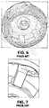
- Figure 4 shows a damaged window of a control cage
- figure 5 shows another window of a control cage where some bars might drop due to the damage on the control cage.
- the bimetal impeller is made up of two different parts: the support parts, the top and the bottom, connected between them by a number of hard metal bars, which represent the wear part of the impeller.
- the present invention intends to solve the above-mentioned problems, among others, existing in the shot blasting turbine field, and in particular in the Foundry Industry. Therefore, the main objectives of the invention are:
- the invention provides a shot blasting turbine according to claim 1.
- Each blade comprises a straight segment followed by a curved one having an active side to propel the abrasive over the surface of the piece and a support side with a lump placed between the straight and the curved segments.
- the impeller comprises a body made up of a single block and a separated central core where the material of the body is harder than the material of the central core.
- the different mechanical resistance of the components is important for the behavior of the whole turbine but too for the behavior of each component independently, so that the mechanical resistance of the material of the lining in the control cage has smaller mechanical resistance than the blades and body of the impeller.
- the material of the body of the impeller and of the blade is tungsten carbide
- the material of the lining is harder tungsten carbide
- the material of the control cage and central core of the impeller is hardened steel.
- a component that can be used with the present invention is a blade for a shot blast turbine, for directing abrasive materials over a surface of a piece, comprising a straight segment followed by a curved one having an active side where the abrasive hits to be directed over the surface of the piece and a support side with a lump placed between the straight and the curved segments of the blade.
- Said lump is needed to place and hold the blade in the grooves practiced in the runner heads where the blade is inserted, and it is also needed to reinforce the curved segment of the blade.
- Said blade is made of tungsten carbide, preferably comprising between 87% and 91% of tungsten (Wc) and preferably between 9 and 13% of cobalt (CO).
- This blade is mechanically stronger than the blades in the state of the art that will resist better the impact of the abrasive material at the same time that is simpler, easier and cheaper to produce than the prior art blades. It will eliminate at least 50% of the accident possibilities of impact with castings inside the blast chamber, saving maintenance costs and equipment breakdown periods
- a control cage for a shot blast turbine comprising at least one exit window to let abrasive material pass on to the blades of the turbine, further comprises at least one lining sector, piece or part covering at least a fourth part of the inside surface of the control cage.
- Said lining sector might be only one that covers all the inside surface of the control cage.
- An alternative to the above construction might be a lining made up of four lining sectors that cover al the inside surface of the control cage.
- the material of said lining is preferable tungsten carbide while the material of the control cage is steel.
- the control cage will prevent the risk of loosening and cheeping of parts capable of damaging the turbine elements or components at the same time that it reduces the wear of the steel support or shell where the inside lining is placed.
- One important objective is to maintain intact the exit window of the shell intact by replacing the inside lining that covers said window. This exit window works as a fuse, so that when the same is damaged prevents the damaging of the rest of the parts of the turbine.
- Another component that can be used with the invention is an impeller for a shot blast turbine, to accelerate abrasive materials towards the blades of the turbine that comprises a body made up of a single block and a separated central core where the material of the body is harder than the material of the central core.
- the material of the body is tungsten carbide while the central core is steel as it is not an area with high risk to wear.
- the impeller due to its properties, eliminates the possibility of accidents due to the impact on different parts of a metal particle mixed on the abrasive material and eliminates the steel support or body of the impellers in the state of the art eliminating therefore the wear of said support or body.
- the above shot blast turbine and components object of the present invention have been designed to solve the described problems existing in the state of the art, and in special in the Foundry industry.
- the blades or blade 10 is made of Tungsten Carbide, composed by two main elements, the Tungsten (Wc) and the Cobalt (Co) on a proportion capable to offer the best compromise between wear resistance and mechanical strength. It is well known that those two physical properties are difficult to conciliate and the benefit of one will deteriorate the performance of the other. The reduction of Tungsten increases the mechanical strength but reduces the wear resistance, while when the Tungsten increases, the contrary happens. After extensive trials and tests it has been concluded that for the foundry application the best composition is a material comprising between 87% and 91% of WC and between 9 and 13% of Co.
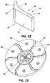
- the blade 10 is placed in grooves 21, 26 located in the runner heads 20, 25, that are the discs of the turbine where the blade 10 is hold.
- runner heads 20, 25 There are two types of runner heads 20, 25, one runner head 20 placed on the motor side of the turbine with grooves 21 on its inner surface 22 and a runner head 25 placed on the abrasive side with grooves 26 too in its inner side 27.
- the motor runner head 20 has a support 24 for connecting to said motor.
- the blades 10 are placed in the grooves 21, 26 and the runner heads are fixed together with the help of screws that get through orifices 23, 28 in both runner heads.
- These runner heads 20, 25 have outside surfaces 29.
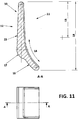
- the geometry of the blade 10 has a straight segment 13 followed by a curved or concave segment 14 on the active side 11 of said blade 10. This is the side 11 that propels the abrasive to the work piece to be shot blasted.
- the straight segment 13 starts from the centre of the turbine and its length varies between 35% and 55% of the total length of the blade 10.
- the curved or concave part 14 continues the straight segment 13 until the extremity of the support runner head 20, 25.
- the back side 12 of the blade 10 has a straight segment 15 followed by a curved or convex segment 16. This is the support side 12 of the blade 10.
- the straight segment 15 length varies from 65% and 75% of the total length of the blade 10.
- this blade 10 eliminates at least 50% of the possibilities of accident by direct contact with the castings inside of the blasting chamber, keeping the qualities and features of a curved blade made of Tungsten carbide, as far as throwing speed is concerned.
- the "lump" 17 on the support 12 side also increases considerably the strength of the blades 10 on the area where contact with a casting may occur, that is to say, the extremity of the blade 10, on the area where the abrasive leaves the blade 10.
- This geometry of the blade 10 is cheaper to produce that the ones in the state of the art and specifically compared to the gamma type curved blade. Compared with this last prior art blade, it has about 20% less material and tungsten carbide is a very expensive metal. It is also easier to produce and to machine. Also the runner heads 20, 25 are made of hard steel that will need less hours to be machined, so a cheaper and faster production. By having only one active surface 13, there is no "obligation" to use the other side 12. This means that once the blade 10 is worn out, even if it has small cracks caused by the wear on the runner heads 20, 25, it will be scrapped a worn out blade 10 and not a blade 10 that had a potential of use and which cost was higher.
- the control cage 30 that can be used with the present invention is made of two different metals, and intents to prevent the problems of the state of the art bimetal control cage, as described previously.
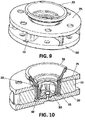
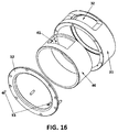
- the control cage 30 comprises a steel support part or shell 31, made of tool steel, machined and heat treated to around 62 HRC with an exit window 32, which size depends on the application, on its surface and an inside lining 40.
- the inside lining protection 40 is made of a monolithic tungsten carbide cylinder 40 that covers the inside of the control cage 30.
- a monolithic cylinder 40 is not covered by the claims.
- This lining not only protects the inside wall of the steel shell 31 of the control cage 30, but also covers fully the exit window 33. As a consequence, the exit window 33 stays as a full and integral window, on its initial dimensions during its working life. This will guaranty the direction of the abrasive from first day throughout the control cage 30 life. With this construction, there are no bars, preferably tungsten bars, that can be chopped from the lining 40 and cause the accidents previously described.
- the steel shell 31 of the control cage will wear faster than the inside lining 40, and this allows the inside lining 40 to be re-used on a new steel shell 32, as the lining 40 will be intact or nearly intact, in one piece, not glued, and very easy to be removed and assembled again.
- the lining 40 is maintained inside the control cage 31 due to a locking ring 32 which is fixed to the control cage with locking pins 33.
- the carbide lining 40 can be used at least with two different steel shells 32, that is to say, it can be used as a replacement. This represents an enormous saving of money and reduces considerably the investment in stocks.
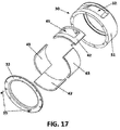
- the lining 40 in order to attend difficult situations in continuous working foundries consists of a lining 40 that covers at least a fourth part or sector of the inside surface of the control cage shell 32.
- the lining 40 would comprise four independent parts, sectors or pieces 42, 43 that together form a lining 40 like the one previously described.
- this new lining 40 divides the inside carbide lining in four parts, sectors or pieces 42, 43. Three of these part or pieces 43 are of similar dimensions and are pure lining.
- the fourth part, sector or piece 42, the one with the window 41, therefore the window sector or window part includes the shape of the window 41 and has a length that will cover the area subjected to the most aggressive wear.
- the control cage 32 has a part or piece that is more fragile than the other components of the turbine, and specially the impeller and the blade.
- the discontinuity of this carbide lining with more than one part or piece 42, 43 instead of a monolithic lining 40, will limit the damage to only one piece instead of to the whole lining, and will leave intact, or almost intact, the other components, specially the impellor and the blade.
- this exit window 32 of the control cage works as a fuse, so that when the same is damaged prevents the damaging of the rest of the parts of the turbine.
- the lining with more than one sector or part 42, 43 therefore non monolithic, has an additional advantage compared with the monolithic solution 40, that it is easier to disassemble and reassemble. So, for those cases when despite the inexistence of foreign metallic inclusions the disassembling may present some difficulty for whatever reason, this sectors carbide lining is an extra option.
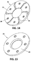
- An impeller 50 that can be used with the present invention is made of a monolithic tungsten carbide wear part or body 51, with a central core 53 in hard steel, where the screw that fixes the impellor 50 to the turbine runner head is tightened.
- This central core 53 is fixed to the body 51 of the impeller 50 with the help of locking pins 54 fixed to hard steel reinforced rings 55.
- This impeller 50 has been developed specially to work together with the previously described control cage 30, although it could be used with other control cages.
- Its arms 52 are fully made of tungsten carbide and its mechanical resistance is higher than that of the window of the control cage, which guarantees its integrity in case of collision with foreign metallic parts mixed on the abrasive stream, due to the mechanic fuse effect of the window control cage.
- This kind of impeller 50 can resist to multiple impacts caused by the foreign metal inclusions in the abrasive stream.
- the thickness, the length and the geometry as well and the curve of the concordance lines have been studied to produce the maximum resilience, while being highly wear resistant. Also the selected tungsten carbide composition has contributed to this success.
- the impeller 50 has no replaceable parts, as it has been designed as a single block or body 51. Once it is worn out, it must be replaced. It is expected that on a cast iron or steel foundry application, this type of new impeller 50 will have a working life at least two times higher than the existing prior art bimetal impeller, with very limited or inexistent breaking of the "arms" 52 followed by detachment of the same, with the consequent damaging to other assembly parts.
- the main advantages of this monolithic carbide impeller are:
Landscapes
- Engineering & Computer Science (AREA)
- Mechanical Engineering (AREA)
- Hydraulic Turbines (AREA)
- Structures Of Non-Positive Displacement Pumps (AREA)
- Turbine Rotor Nozzle Sealing (AREA)
Claims (5)
- Turbine de grenaillage pour lancer des matériaux abrasifs sur une surface d'une pièce à grenailler, avec au moins deux aubes (10) pour diriger l'abrasif sur la surface de la pièce et placées entre deux têtes de roue (20, 25), un rotor (50) qui accélère l'abrasif vers l'aube (10), et une cage de commande (31) avec une ouverture ou fenêtre (32) de laquelle l'abrasif part du rotor (50) jusqu'à l'aube (10), caractérisée en ce que ladite cage de commande (31) comprend deux, trois ou quatre zones, pièces ou parties de doublure (42, 43) au moins une zone (43), pièce ou partie de doublure recouvrant au moins un quart de la surface intérieure de la cage de commande (31), dans laquelle l'une des zones, pièces ou parties (42) inclut une fenêtre (41).
- Turbine, selon la revendication 1, caractérisée en ce que ladite aube (10) comprend un segment droit (13) suivi d'un autre courbé (14) ayant un côté actif (11) pour propulser l'abrasif sur la surface de la pièce et un côté de support (12) avec une bosse (17) placé entre les segments droit (15) et courbé (16).
- Turbine, selon la revendication 1, caractérisée en ce que ledit rotor (50) comprend un corps (51) fait en un seul bloc et un noyau central (53) séparé où le matériau du corps (51) est plus dur que le matériau du noyau central (53).
- Turbine, selon l'une quelconque des revendications précédentes, caractérisée en ce que la résistance mécanique du matériau de la doublure (43) dans la cage de commande (31) a une résistance mécanique plus petite que les aubes (10) et le corps (51) du rotor (50).
- Turbine, selon l'une quelconque des revendications précédentes, caractérisée en ce que le matériau du corps (51) du rotor (50) et de l'aube (10) est du carbure de tungstène, le matériau de la doublure (43) est du carbure et le matériau de la cage de commande (31) et du noyau central (53) du rotor (50) est de l'acier.
Priority Applications (6)
| Application Number | Priority Date | Filing Date | Title |
|---|---|---|---|
| EP14181592.8A EP2829361A1 (fr) | 2013-07-19 | 2013-07-19 | Turbine pour turbine de grenaillage et composants |
| PT141815829T PT2829362E (pt) | 2013-07-19 | 2013-07-19 | Palheta para uma turbina de decapagem e componentes |
| EP14181587.8A EP2829360B1 (fr) | 2013-07-19 | 2013-07-19 | Cage de commande destinée à une turbine de grenaillage et composants |
| EP13398011.0A EP2826593B1 (fr) | 2013-07-19 | 2013-07-19 | Composants et turbine de grenaillage |
| EP14181582.9A EP2829362B1 (fr) | 2013-07-19 | 2013-07-19 | Lame pour composants et turbine de grenaillage |
| PT141815878T PT2829360E (pt) | 2013-07-19 | 2013-07-19 | Caixa de controlo para uma turbina de decapagem e componentes |
Applications Claiming Priority (1)
| Application Number | Priority Date | Filing Date | Title |
|---|---|---|---|
| EP13398011.0A EP2826593B1 (fr) | 2013-07-19 | 2013-07-19 | Composants et turbine de grenaillage |
Related Child Applications (6)
| Application Number | Title | Priority Date | Filing Date |
|---|---|---|---|
| EP14181587.8A Division-Into EP2829360B1 (fr) | 2013-07-19 | 2013-07-19 | Cage de commande destinée à une turbine de grenaillage et composants |
| EP14181587.8A Division EP2829360B1 (fr) | 2013-07-19 | 2013-07-19 | Cage de commande destinée à une turbine de grenaillage et composants |
| EP14181592.8A Division-Into EP2829361A1 (fr) | 2013-07-19 | 2013-07-19 | Turbine pour turbine de grenaillage et composants |
| EP14181592.8A Division EP2829361A1 (fr) | 2013-07-19 | 2013-07-19 | Turbine pour turbine de grenaillage et composants |
| EP14181582.9A Division-Into EP2829362B1 (fr) | 2013-07-19 | 2013-07-19 | Lame pour composants et turbine de grenaillage |
| EP14181582.9A Division EP2829362B1 (fr) | 2013-07-19 | 2013-07-19 | Lame pour composants et turbine de grenaillage |
Publications (2)
| Publication Number | Publication Date |
|---|---|
| EP2826593A1 EP2826593A1 (fr) | 2015-01-21 |
| EP2826593B1 true EP2826593B1 (fr) | 2016-03-30 |
Family
ID=48998554
Family Applications (4)
| Application Number | Title | Priority Date | Filing Date |
|---|---|---|---|
| EP13398011.0A Active EP2826593B1 (fr) | 2013-07-19 | 2013-07-19 | Composants et turbine de grenaillage |
| EP14181582.9A Active EP2829362B1 (fr) | 2013-07-19 | 2013-07-19 | Lame pour composants et turbine de grenaillage |
| EP14181592.8A Withdrawn EP2829361A1 (fr) | 2013-07-19 | 2013-07-19 | Turbine pour turbine de grenaillage et composants |
| EP14181587.8A Active EP2829360B1 (fr) | 2013-07-19 | 2013-07-19 | Cage de commande destinée à une turbine de grenaillage et composants |
Family Applications After (3)
| Application Number | Title | Priority Date | Filing Date |
|---|---|---|---|
| EP14181582.9A Active EP2829362B1 (fr) | 2013-07-19 | 2013-07-19 | Lame pour composants et turbine de grenaillage |
| EP14181592.8A Withdrawn EP2829361A1 (fr) | 2013-07-19 | 2013-07-19 | Turbine pour turbine de grenaillage et composants |
| EP14181587.8A Active EP2829360B1 (fr) | 2013-07-19 | 2013-07-19 | Cage de commande destinée à une turbine de grenaillage et composants |
Country Status (2)
| Country | Link |
|---|---|
| EP (4) | EP2826593B1 (fr) |
| PT (2) | PT2829362E (fr) |
Cited By (1)
| Publication number | Priority date | Publication date | Assignee | Title |
|---|---|---|---|---|
| EP3197638A4 (fr) * | 2014-09-25 | 2018-08-29 | Wheelabrator Group Limited | Pale pour machine à roue de projection centrifuge et procédé d'entretien d'une machine à roue de projection centrifuge |
Families Citing this family (7)
| Publication number | Priority date | Publication date | Assignee | Title |
|---|---|---|---|---|
| BR112016009332B1 (pt) * | 2013-10-31 | 2021-02-02 | Sintokogio, Ltd | unidade de placa lateral, e, projetor centrífugo |
| CN106425886A (zh) * | 2016-11-04 | 2017-02-22 | 济南大学 | Y型叶片抛丸器 |
| CN106425885A (zh) * | 2016-11-04 | 2017-02-22 | 济南大学 | V型叶片抛丸器 |
| CN106891268B (zh) * | 2017-04-05 | 2023-04-14 | 济南大学 | 抛丸器叶片及叶轮结构 |
| CN107378799B (zh) * | 2017-09-18 | 2023-09-26 | 济南大学 | 抛丸器 |
| CN110253458B (zh) * | 2019-06-13 | 2024-05-14 | 镇江蓝舶科技股份有限公司 | 一种用于路缘石抛丸机的侧抛丸口磁性密封装置 |
| CN110625537A (zh) * | 2019-09-06 | 2019-12-31 | 昆山亚比斯环保包装材料有限公司 | 一种喷击机台的叶轮设备及喷击机台 |
Citations (1)
| Publication number | Priority date | Publication date | Assignee | Title |
|---|---|---|---|---|
| DE10104703C1 (de) * | 2001-02-02 | 2001-12-06 | Schlick Jennifer | Schleuderradanordnung |
Family Cites Families (6)
| Publication number | Priority date | Publication date | Assignee | Title |
|---|---|---|---|---|
| GB1003441A (en) * | 1963-04-18 | 1965-09-02 | Spencer & Halstead Ltd | Blades for the impellers of blast-cleaning machines |
| US3867791A (en) * | 1974-05-13 | 1975-02-25 | James R Goff | Abrasive blasting machine |
| DE4410629A1 (de) * | 1994-03-26 | 1995-09-28 | Schlick Roto Jet Masch | Schleuderrad mit Verteilerrad |
| DE10216819A1 (de) * | 2002-04-16 | 2003-11-06 | Roesler Oberflaechentechnik Gm | Einstellhülse |
| BE1015168A3 (fr) * | 2002-11-04 | 2004-10-05 | Rutten S A | Piece de controle et distributeur pour alimentation de turbine de grenaillage centrifuge et leur utilisation. |
| EP1543922A1 (fr) * | 2003-12-15 | 2005-06-22 | Rutten SA-NV | Turbine de grenaillage à hautes performances équipée de palettes réversibles |
-
2013
- 2013-07-19 EP EP13398011.0A patent/EP2826593B1/fr active Active
- 2013-07-19 EP EP14181582.9A patent/EP2829362B1/fr active Active
- 2013-07-19 PT PT141815829T patent/PT2829362E/pt unknown
- 2013-07-19 PT PT141815878T patent/PT2829360E/pt unknown
- 2013-07-19 EP EP14181592.8A patent/EP2829361A1/fr not_active Withdrawn
- 2013-07-19 EP EP14181587.8A patent/EP2829360B1/fr active Active
Patent Citations (1)
| Publication number | Priority date | Publication date | Assignee | Title |
|---|---|---|---|---|
| DE10104703C1 (de) * | 2001-02-02 | 2001-12-06 | Schlick Jennifer | Schleuderradanordnung |
Cited By (1)
| Publication number | Priority date | Publication date | Assignee | Title |
|---|---|---|---|---|
| EP3197638A4 (fr) * | 2014-09-25 | 2018-08-29 | Wheelabrator Group Limited | Pale pour machine à roue de projection centrifuge et procédé d'entretien d'une machine à roue de projection centrifuge |
Also Published As
| Publication number | Publication date |
|---|---|
| EP2829361A1 (fr) | 2015-01-28 |
| PT2829362E (pt) | 2016-01-22 |
| EP2829362A1 (fr) | 2015-01-28 |
| PT2829360E (pt) | 2016-01-22 |
| EP2829360B1 (fr) | 2015-09-16 |
| EP2829362B1 (fr) | 2015-09-30 |
| EP2829360A1 (fr) | 2015-01-28 |
| EP2826593A1 (fr) | 2015-01-21 |
Similar Documents
| Publication | Publication Date | Title |
|---|---|---|
| EP2826593B1 (fr) | Composants et turbine de grenaillage | |
| US20130233955A1 (en) | Shredder hammers | |
| US10471435B2 (en) | Hammer for shredding machines | |
| US20030213861A1 (en) | Crusher wear components | |
| CN102413937A (zh) | 锤子销与锤子之间的接合得到改善的破碎器锤子 | |
| US7028936B2 (en) | Wear bars for impellers | |
| US10022724B2 (en) | Stepped shredder hammers | |
| US11668315B2 (en) | Composite metal component and method of producing same | |
| US20030178516A1 (en) | Replaceable grate device for maximizing the throughput of solid material in ore mills | |
| JP5048965B2 (ja) | ハンマーヘッド | |
| JP5258126B1 (ja) | ハンマーヘッドおよびその製造方法、並びに該ハンマーヘッドを有する破砕機 | |
| CA1071603A (fr) | Pulverisateur | |
| CN209754926U (zh) | 一种抛头以及具有该抛头的抛丸机 | |
| CN106000545B (zh) | 一种冲击式破碎机的抛料头装置及冲击式破碎机 | |
| CN218573814U (zh) | 一种加强型中速磨煤机喷嘴环 | |
| WO1996038247A1 (fr) | Pale de soufflante | |
| CN216987973U (zh) | 一种冲击式破碎机的开式转轮及其破碎机 | |
| KR200400399Y1 (ko) | 샌드블래스팅 기구 | |
| Durman | Observations on the use of hard-metal castings in the shot-blasting industry | |
| KR20070024201A (ko) | 샌드블래스팅 기구 | |
| JPH02237653A (ja) | 遠心式衝撃紛砕機 |
Legal Events
| Date | Code | Title | Description |
|---|---|---|---|
| 17P | Request for examination filed |
Effective date: 20130719 |
|
| AK | Designated contracting states |
Kind code of ref document: A1 Designated state(s): AL AT BE BG CH CY CZ DE DK EE ES FI FR GB GR HR HU IE IS IT LI LT LU LV MC MK MT NL NO PL PT RO RS SE SI SK SM TR |
|
| AX | Request for extension of the european patent |
Extension state: BA ME |
|
| PUAI | Public reference made under article 153(3) epc to a published international application that has entered the european phase |
Free format text: ORIGINAL CODE: 0009012 |
|
| R17P | Request for examination filed (corrected) |
Effective date: 20150427 |
|
| RBV | Designated contracting states (corrected) |
Designated state(s): AL AT BE BG CH CY CZ DE DK EE ES FI FR GB GR HR HU IE IS IT LI LT LU LV MC MK MT NL NO PL PT RO RS SE SI SK SM TR |
|
| GRAP | Despatch of communication of intention to grant a patent |
Free format text: ORIGINAL CODE: EPIDOSNIGR1 |
|
| INTG | Intention to grant announced |
Effective date: 20160111 |
|
| GRAS | Grant fee paid |
Free format text: ORIGINAL CODE: EPIDOSNIGR3 |
|
| GRAA | (expected) grant |
Free format text: ORIGINAL CODE: 0009210 |
|
| AK | Designated contracting states |
Kind code of ref document: B1 Designated state(s): AL AT BE BG CH CY CZ DE DK EE ES FI FR GB GR HR HU IE IS IT LI LT LU LV MC MK MT NL NO PL PT RO RS SE SI SK SM TR |
|
| REG | Reference to a national code |
Ref country code: GB Ref legal event code: FG4D |
|
| REG | Reference to a national code |
Ref country code: CH Ref legal event code: EP |
|
| REG | Reference to a national code |
Ref country code: AT Ref legal event code: REF Ref document number: 784826 Country of ref document: AT Kind code of ref document: T Effective date: 20160415 |
|
| REG | Reference to a national code |
Ref country code: IE Ref legal event code: FG4D |
|
| REG | Reference to a national code |
Ref country code: PT Ref legal event code: SC4A Free format text: AVAILABILITY OF NATIONAL TRANSLATION Effective date: 20160420 |
|
| REG | Reference to a national code |
Ref country code: DE Ref legal event code: R096 Ref document number: 602013005915 Country of ref document: DE |
|
| REG | Reference to a national code |
Ref country code: LT Ref legal event code: MG4D |
|
| REG | Reference to a national code |
Ref country code: FR Ref legal event code: PLFP Year of fee payment: 4 |
|
| PG25 | Lapsed in a contracting state [announced via postgrant information from national office to epo] |
Ref country code: HR Free format text: LAPSE BECAUSE OF FAILURE TO SUBMIT A TRANSLATION OF THE DESCRIPTION OR TO PAY THE FEE WITHIN THE PRESCRIBED TIME-LIMIT Effective date: 20160330 Ref country code: GR Free format text: LAPSE BECAUSE OF FAILURE TO SUBMIT A TRANSLATION OF THE DESCRIPTION OR TO PAY THE FEE WITHIN THE PRESCRIBED TIME-LIMIT Effective date: 20160701 Ref country code: FI Free format text: LAPSE BECAUSE OF FAILURE TO SUBMIT A TRANSLATION OF THE DESCRIPTION OR TO PAY THE FEE WITHIN THE PRESCRIBED TIME-LIMIT Effective date: 20160330 Ref country code: NO Free format text: LAPSE BECAUSE OF FAILURE TO SUBMIT A TRANSLATION OF THE DESCRIPTION OR TO PAY THE FEE WITHIN THE PRESCRIBED TIME-LIMIT Effective date: 20160630 |
|
| REG | Reference to a national code |
Ref country code: NL Ref legal event code: MP Effective date: 20160330 |
|
| REG | Reference to a national code |
Ref country code: AT Ref legal event code: MK05 Ref document number: 784826 Country of ref document: AT Kind code of ref document: T Effective date: 20160330 |
|
| PG25 | Lapsed in a contracting state [announced via postgrant information from national office to epo] |
Ref country code: LT Free format text: LAPSE BECAUSE OF FAILURE TO SUBMIT A TRANSLATION OF THE DESCRIPTION OR TO PAY THE FEE WITHIN THE PRESCRIBED TIME-LIMIT Effective date: 20160330 Ref country code: LV Free format text: LAPSE BECAUSE OF FAILURE TO SUBMIT A TRANSLATION OF THE DESCRIPTION OR TO PAY THE FEE WITHIN THE PRESCRIBED TIME-LIMIT Effective date: 20160330 Ref country code: RS Free format text: LAPSE BECAUSE OF FAILURE TO SUBMIT A TRANSLATION OF THE DESCRIPTION OR TO PAY THE FEE WITHIN THE PRESCRIBED TIME-LIMIT Effective date: 20160330 Ref country code: SE Free format text: LAPSE BECAUSE OF FAILURE TO SUBMIT A TRANSLATION OF THE DESCRIPTION OR TO PAY THE FEE WITHIN THE PRESCRIBED TIME-LIMIT Effective date: 20160330 |
|
| PG25 | Lapsed in a contracting state [announced via postgrant information from national office to epo] |
Ref country code: NL Free format text: LAPSE BECAUSE OF FAILURE TO SUBMIT A TRANSLATION OF THE DESCRIPTION OR TO PAY THE FEE WITHIN THE PRESCRIBED TIME-LIMIT Effective date: 20160330 |
|
| PG25 | Lapsed in a contracting state [announced via postgrant information from national office to epo] |
Ref country code: EE Free format text: LAPSE BECAUSE OF FAILURE TO SUBMIT A TRANSLATION OF THE DESCRIPTION OR TO PAY THE FEE WITHIN THE PRESCRIBED TIME-LIMIT Effective date: 20160330 Ref country code: IS Free format text: LAPSE BECAUSE OF FAILURE TO SUBMIT A TRANSLATION OF THE DESCRIPTION OR TO PAY THE FEE WITHIN THE PRESCRIBED TIME-LIMIT Effective date: 20160730 Ref country code: PL Free format text: LAPSE BECAUSE OF FAILURE TO SUBMIT A TRANSLATION OF THE DESCRIPTION OR TO PAY THE FEE WITHIN THE PRESCRIBED TIME-LIMIT Effective date: 20160330 |
|
| PG25 | Lapsed in a contracting state [announced via postgrant information from national office to epo] |
Ref country code: SK Free format text: LAPSE BECAUSE OF FAILURE TO SUBMIT A TRANSLATION OF THE DESCRIPTION OR TO PAY THE FEE WITHIN THE PRESCRIBED TIME-LIMIT Effective date: 20160330 Ref country code: ES Free format text: LAPSE BECAUSE OF FAILURE TO SUBMIT A TRANSLATION OF THE DESCRIPTION OR TO PAY THE FEE WITHIN THE PRESCRIBED TIME-LIMIT Effective date: 20160330 Ref country code: SM Free format text: LAPSE BECAUSE OF FAILURE TO SUBMIT A TRANSLATION OF THE DESCRIPTION OR TO PAY THE FEE WITHIN THE PRESCRIBED TIME-LIMIT Effective date: 20160330 Ref country code: AT Free format text: LAPSE BECAUSE OF FAILURE TO SUBMIT A TRANSLATION OF THE DESCRIPTION OR TO PAY THE FEE WITHIN THE PRESCRIBED TIME-LIMIT Effective date: 20160330 Ref country code: RO Free format text: LAPSE BECAUSE OF FAILURE TO SUBMIT A TRANSLATION OF THE DESCRIPTION OR TO PAY THE FEE WITHIN THE PRESCRIBED TIME-LIMIT Effective date: 20160330 Ref country code: CZ Free format text: LAPSE BECAUSE OF FAILURE TO SUBMIT A TRANSLATION OF THE DESCRIPTION OR TO PAY THE FEE WITHIN THE PRESCRIBED TIME-LIMIT Effective date: 20160330 |
|
| PG25 | Lapsed in a contracting state [announced via postgrant information from national office to epo] |
Ref country code: BE Free format text: LAPSE BECAUSE OF FAILURE TO SUBMIT A TRANSLATION OF THE DESCRIPTION OR TO PAY THE FEE WITHIN THE PRESCRIBED TIME-LIMIT Effective date: 20160330 Ref country code: IT Free format text: LAPSE BECAUSE OF FAILURE TO SUBMIT A TRANSLATION OF THE DESCRIPTION OR TO PAY THE FEE WITHIN THE PRESCRIBED TIME-LIMIT Effective date: 20160330 |
|
| REG | Reference to a national code |
Ref country code: DE Ref legal event code: R097 Ref document number: 602013005915 Country of ref document: DE |
|
| PG25 | Lapsed in a contracting state [announced via postgrant information from national office to epo] |
Ref country code: DK Free format text: LAPSE BECAUSE OF FAILURE TO SUBMIT A TRANSLATION OF THE DESCRIPTION OR TO PAY THE FEE WITHIN THE PRESCRIBED TIME-LIMIT Effective date: 20160330 |
|
| PLBE | No opposition filed within time limit |
Free format text: ORIGINAL CODE: 0009261 |
|
| STAA | Information on the status of an ep patent application or granted ep patent |
Free format text: STATUS: NO OPPOSITION FILED WITHIN TIME LIMIT |
|
| REG | Reference to a national code |
Ref country code: CH Ref legal event code: PL |
|
| 26N | No opposition filed |
Effective date: 20170103 |
|
| PG25 | Lapsed in a contracting state [announced via postgrant information from national office to epo] |
Ref country code: MC Free format text: LAPSE BECAUSE OF FAILURE TO SUBMIT A TRANSLATION OF THE DESCRIPTION OR TO PAY THE FEE WITHIN THE PRESCRIBED TIME-LIMIT Effective date: 20160330 |
|
| PG25 | Lapsed in a contracting state [announced via postgrant information from national office to epo] |
Ref country code: CH Free format text: LAPSE BECAUSE OF NON-PAYMENT OF DUE FEES Effective date: 20160731 Ref country code: LI Free format text: LAPSE BECAUSE OF NON-PAYMENT OF DUE FEES Effective date: 20160731 |
|
| REG | Reference to a national code |
Ref country code: IE Ref legal event code: MM4A |
|
| PG25 | Lapsed in a contracting state [announced via postgrant information from national office to epo] |
Ref country code: SI Free format text: LAPSE BECAUSE OF FAILURE TO SUBMIT A TRANSLATION OF THE DESCRIPTION OR TO PAY THE FEE WITHIN THE PRESCRIBED TIME-LIMIT Effective date: 20160330 |
|
| REG | Reference to a national code |
Ref country code: FR Ref legal event code: PLFP Year of fee payment: 5 |
|
| PG25 | Lapsed in a contracting state [announced via postgrant information from national office to epo] |
Ref country code: IE Free format text: LAPSE BECAUSE OF NON-PAYMENT OF DUE FEES Effective date: 20160719 |
|
| PG25 | Lapsed in a contracting state [announced via postgrant information from national office to epo] |
Ref country code: LU Free format text: LAPSE BECAUSE OF NON-PAYMENT OF DUE FEES Effective date: 20160719 |
|
| PG25 | Lapsed in a contracting state [announced via postgrant information from national office to epo] |
Ref country code: HU Free format text: LAPSE BECAUSE OF FAILURE TO SUBMIT A TRANSLATION OF THE DESCRIPTION OR TO PAY THE FEE WITHIN THE PRESCRIBED TIME-LIMIT; INVALID AB INITIO Effective date: 20130719 |
|
| PG25 | Lapsed in a contracting state [announced via postgrant information from national office to epo] |
Ref country code: MK Free format text: LAPSE BECAUSE OF FAILURE TO SUBMIT A TRANSLATION OF THE DESCRIPTION OR TO PAY THE FEE WITHIN THE PRESCRIBED TIME-LIMIT Effective date: 20160330 Ref country code: CY Free format text: LAPSE BECAUSE OF FAILURE TO SUBMIT A TRANSLATION OF THE DESCRIPTION OR TO PAY THE FEE WITHIN THE PRESCRIBED TIME-LIMIT Effective date: 20160330 Ref country code: MT Free format text: LAPSE BECAUSE OF NON-PAYMENT OF DUE FEES Effective date: 20160731 |
|
| REG | Reference to a national code |
Ref country code: FR Ref legal event code: PLFP Year of fee payment: 6 |
|
| PG25 | Lapsed in a contracting state [announced via postgrant information from national office to epo] |
Ref country code: BG Free format text: LAPSE BECAUSE OF FAILURE TO SUBMIT A TRANSLATION OF THE DESCRIPTION OR TO PAY THE FEE WITHIN THE PRESCRIBED TIME-LIMIT Effective date: 20160330 |
|
| PG25 | Lapsed in a contracting state [announced via postgrant information from national office to epo] |
Ref country code: TR Free format text: LAPSE BECAUSE OF FAILURE TO SUBMIT A TRANSLATION OF THE DESCRIPTION OR TO PAY THE FEE WITHIN THE PRESCRIBED TIME-LIMIT Effective date: 20160330 Ref country code: AL Free format text: LAPSE BECAUSE OF FAILURE TO SUBMIT A TRANSLATION OF THE DESCRIPTION OR TO PAY THE FEE WITHIN THE PRESCRIBED TIME-LIMIT Effective date: 20160330 |
|
| PGFP | Annual fee paid to national office [announced via postgrant information from national office to epo] |
Ref country code: PT Payment date: 20250702 Year of fee payment: 13 |
|
| PGFP | Annual fee paid to national office [announced via postgrant information from national office to epo] |
Ref country code: DE Payment date: 20250729 Year of fee payment: 13 |
|
| PGFP | Annual fee paid to national office [announced via postgrant information from national office to epo] |
Ref country code: GB Payment date: 20250728 Year of fee payment: 13 |
|
| PGFP | Annual fee paid to national office [announced via postgrant information from national office to epo] |
Ref country code: FR Payment date: 20250725 Year of fee payment: 13 |