EP2826662B1 - Siège de sécurité enfant - Google Patents
Siège de sécurité enfant Download PDFInfo
- Publication number
- EP2826662B1 EP2826662B1 EP13003568.6A EP13003568A EP2826662B1 EP 2826662 B1 EP2826662 B1 EP 2826662B1 EP 13003568 A EP13003568 A EP 13003568A EP 2826662 B1 EP2826662 B1 EP 2826662B1
- Authority
- EP
- European Patent Office
- Prior art keywords
- safety seat
- child safety
- component
- impact
- outer shell
- Prior art date
- Legal status (The legal status is an assumption and is not a legal conclusion. Google has not performed a legal analysis and makes no representation as to the accuracy of the status listed.)
- Active
Links
Images


Classifications
-
- B—PERFORMING OPERATIONS; TRANSPORTING
- B60—VEHICLES IN GENERAL
- B60N—SEATS SPECIALLY ADAPTED FOR VEHICLES; VEHICLE PASSENGER ACCOMMODATION NOT OTHERWISE PROVIDED FOR
- B60N2/00—Seats specially adapted for vehicles; Arrangement or mounting of seats in vehicles
- B60N2/24—Seats specially adapted for vehicles; Arrangement or mounting of seats in vehicles for particular purposes or particular vehicles
- B60N2/26—Seats specially adapted for vehicles; Arrangement or mounting of seats in vehicles for particular purposes or particular vehicles for children
- B60N2/28—Seats readily mountable on, and dismountable from, existing seats or other parts of the vehicle
- B60N2/2884—Seats readily mountable on, and dismountable from, existing seats or other parts of the vehicle with protection systems against abnormal g-forces
-
- B—PERFORMING OPERATIONS; TRANSPORTING
- B60—VEHICLES IN GENERAL
- B60N—SEATS SPECIALLY ADAPTED FOR VEHICLES; VEHICLE PASSENGER ACCOMMODATION NOT OTHERWISE PROVIDED FOR
- B60N2/00—Seats specially adapted for vehicles; Arrangement or mounting of seats in vehicles
- B60N2/24—Seats specially adapted for vehicles; Arrangement or mounting of seats in vehicles for particular purposes or particular vehicles
- B60N2/26—Seats specially adapted for vehicles; Arrangement or mounting of seats in vehicles for particular purposes or particular vehicles for children
- B60N2/28—Seats readily mountable on, and dismountable from, existing seats or other parts of the vehicle
-
- B—PERFORMING OPERATIONS; TRANSPORTING
- B60—VEHICLES IN GENERAL
- B60N—SEATS SPECIALLY ADAPTED FOR VEHICLES; VEHICLE PASSENGER ACCOMMODATION NOT OTHERWISE PROVIDED FOR
- B60N2/00—Seats specially adapted for vehicles; Arrangement or mounting of seats in vehicles
- B60N2/24—Seats specially adapted for vehicles; Arrangement or mounting of seats in vehicles for particular purposes or particular vehicles
- B60N2/26—Seats specially adapted for vehicles; Arrangement or mounting of seats in vehicles for particular purposes or particular vehicles for children
- B60N2/28—Seats readily mountable on, and dismountable from, existing seats or other parts of the vehicle
- B60N2/2866—Seats readily mountable on, and dismountable from, existing seats or other parts of the vehicle booster cushions, e.g. to lift a child to allow proper use of the conventional safety belts
-
- B—PERFORMING OPERATIONS; TRANSPORTING
- B60—VEHICLES IN GENERAL
- B60N—SEATS SPECIALLY ADAPTED FOR VEHICLES; VEHICLE PASSENGER ACCOMMODATION NOT OTHERWISE PROVIDED FOR
- B60N2/00—Seats specially adapted for vehicles; Arrangement or mounting of seats in vehicles
- B60N2/24—Seats specially adapted for vehicles; Arrangement or mounting of seats in vehicles for particular purposes or particular vehicles
- B60N2/26—Seats specially adapted for vehicles; Arrangement or mounting of seats in vehicles for particular purposes or particular vehicles for children
- B60N2/28—Seats readily mountable on, and dismountable from, existing seats or other parts of the vehicle
- B60N2/2872—Seats readily mountable on, and dismountable from, existing seats or other parts of the vehicle provided with side rests
-
- B—PERFORMING OPERATIONS; TRANSPORTING
- B60—VEHICLES IN GENERAL
- B60N—SEATS SPECIALLY ADAPTED FOR VEHICLES; VEHICLE PASSENGER ACCOMMODATION NOT OTHERWISE PROVIDED FOR
- B60N2/00—Seats specially adapted for vehicles; Arrangement or mounting of seats in vehicles
- B60N2/24—Seats specially adapted for vehicles; Arrangement or mounting of seats in vehicles for particular purposes or particular vehicles
- B60N2/42—Seats specially adapted for vehicles; Arrangement or mounting of seats in vehicles for particular purposes or particular vehicles the seat constructed to protect the occupant from the effect of abnormal g-forces, e.g. crash or safety seats
-
- B—PERFORMING OPERATIONS; TRANSPORTING
- B60—VEHICLES IN GENERAL
- B60N—SEATS SPECIALLY ADAPTED FOR VEHICLES; VEHICLE PASSENGER ACCOMMODATION NOT OTHERWISE PROVIDED FOR
- B60N2/00—Seats specially adapted for vehicles; Arrangement or mounting of seats in vehicles
- B60N2/24—Seats specially adapted for vehicles; Arrangement or mounting of seats in vehicles for particular purposes or particular vehicles
- B60N2/26—Seats specially adapted for vehicles; Arrangement or mounting of seats in vehicles for particular purposes or particular vehicles for children
- B60N2/28—Seats readily mountable on, and dismountable from, existing seats or other parts of the vehicle
- B60N2/2851—Seats readily mountable on, and dismountable from, existing seats or other parts of the vehicle provided with head-rests
-
- B—PERFORMING OPERATIONS; TRANSPORTING
- B60—VEHICLES IN GENERAL
- B60N—SEATS SPECIALLY ADAPTED FOR VEHICLES; VEHICLE PASSENGER ACCOMMODATION NOT OTHERWISE PROVIDED FOR
- B60N2/00—Seats specially adapted for vehicles; Arrangement or mounting of seats in vehicles
- B60N2/24—Seats specially adapted for vehicles; Arrangement or mounting of seats in vehicles for particular purposes or particular vehicles
- B60N2/26—Seats specially adapted for vehicles; Arrangement or mounting of seats in vehicles for particular purposes or particular vehicles for children
- B60N2/28—Seats readily mountable on, and dismountable from, existing seats or other parts of the vehicle
- B60N2/2857—Seats readily mountable on, and dismountable from, existing seats or other parts of the vehicle characterised by the peculiar orientation of the child
- B60N2/286—Seats readily mountable on, and dismountable from, existing seats or other parts of the vehicle characterised by the peculiar orientation of the child forward facing
-
- B—PERFORMING OPERATIONS; TRANSPORTING
- B60—VEHICLES IN GENERAL
- B60N—SEATS SPECIALLY ADAPTED FOR VEHICLES; VEHICLE PASSENGER ACCOMMODATION NOT OTHERWISE PROVIDED FOR
- B60N2/00—Seats specially adapted for vehicles; Arrangement or mounting of seats in vehicles
- B60N2/24—Seats specially adapted for vehicles; Arrangement or mounting of seats in vehicles for particular purposes or particular vehicles
- B60N2/26—Seats specially adapted for vehicles; Arrangement or mounting of seats in vehicles for particular purposes or particular vehicles for children
- B60N2/28—Seats readily mountable on, and dismountable from, existing seats or other parts of the vehicle
- B60N2/2881—Upholstery, padded or cushioned members therefor
-
- B—PERFORMING OPERATIONS; TRANSPORTING
- B60—VEHICLES IN GENERAL
- B60N—SEATS SPECIALLY ADAPTED FOR VEHICLES; VEHICLE PASSENGER ACCOMMODATION NOT OTHERWISE PROVIDED FOR
- B60N2/00—Seats specially adapted for vehicles; Arrangement or mounting of seats in vehicles
- B60N2/24—Seats specially adapted for vehicles; Arrangement or mounting of seats in vehicles for particular purposes or particular vehicles
- B60N2/42—Seats specially adapted for vehicles; Arrangement or mounting of seats in vehicles for particular purposes or particular vehicles the seat constructed to protect the occupant from the effect of abnormal g-forces, e.g. crash or safety seats
- B60N2/4207—Seats specially adapted for vehicles; Arrangement or mounting of seats in vehicles for particular purposes or particular vehicles the seat constructed to protect the occupant from the effect of abnormal g-forces, e.g. crash or safety seats characterised by the direction of the g-forces
- B60N2/4214—Seats specially adapted for vehicles; Arrangement or mounting of seats in vehicles for particular purposes or particular vehicles the seat constructed to protect the occupant from the effect of abnormal g-forces, e.g. crash or safety seats characterised by the direction of the g-forces longitudinal
- B60N2/4228—Seats specially adapted for vehicles; Arrangement or mounting of seats in vehicles for particular purposes or particular vehicles the seat constructed to protect the occupant from the effect of abnormal g-forces, e.g. crash or safety seats characterised by the direction of the g-forces longitudinal due to impact coming from the rear
-
- B—PERFORMING OPERATIONS; TRANSPORTING
- B60—VEHICLES IN GENERAL
- B60N—SEATS SPECIALLY ADAPTED FOR VEHICLES; VEHICLE PASSENGER ACCOMMODATION NOT OTHERWISE PROVIDED FOR
- B60N2/00—Seats specially adapted for vehicles; Arrangement or mounting of seats in vehicles
- B60N2/24—Seats specially adapted for vehicles; Arrangement or mounting of seats in vehicles for particular purposes or particular vehicles
- B60N2/42—Seats specially adapted for vehicles; Arrangement or mounting of seats in vehicles for particular purposes or particular vehicles the seat constructed to protect the occupant from the effect of abnormal g-forces, e.g. crash or safety seats
- B60N2/4207—Seats specially adapted for vehicles; Arrangement or mounting of seats in vehicles for particular purposes or particular vehicles the seat constructed to protect the occupant from the effect of abnormal g-forces, e.g. crash or safety seats characterised by the direction of the g-forces
- B60N2/4235—Seats specially adapted for vehicles; Arrangement or mounting of seats in vehicles for particular purposes or particular vehicles the seat constructed to protect the occupant from the effect of abnormal g-forces, e.g. crash or safety seats characterised by the direction of the g-forces transversal
-
- B—PERFORMING OPERATIONS; TRANSPORTING
- B60—VEHICLES IN GENERAL
- B60N—SEATS SPECIALLY ADAPTED FOR VEHICLES; VEHICLE PASSENGER ACCOMMODATION NOT OTHERWISE PROVIDED FOR
- B60N2/00—Seats specially adapted for vehicles; Arrangement or mounting of seats in vehicles
- B60N2/24—Seats specially adapted for vehicles; Arrangement or mounting of seats in vehicles for particular purposes or particular vehicles
- B60N2/42—Seats specially adapted for vehicles; Arrangement or mounting of seats in vehicles for particular purposes or particular vehicles the seat constructed to protect the occupant from the effect of abnormal g-forces, e.g. crash or safety seats
- B60N2/427—Seats or parts thereof displaced during a crash
- B60N2/42709—Seats or parts thereof displaced during a crash involving residual deformation or fracture of the structure
-
- B—PERFORMING OPERATIONS; TRANSPORTING
- B60—VEHICLES IN GENERAL
- B60R—VEHICLES, VEHICLE FITTINGS, OR VEHICLE PARTS, NOT OTHERWISE PROVIDED FOR
- B60R21/00—Arrangements or fittings on vehicles for protecting or preventing injuries to occupants or pedestrians in case of accidents or other traffic risks
- B60R21/02—Occupant safety arrangements or fittings, e.g. crash pads
- B60R21/16—Inflatable occupant restraints or confinements designed to inflate upon impact or impending impact, e.g. air bags
- B60R21/20—Arrangements for storing inflatable members in their non-use or deflated condition; Arrangement or mounting of air bag modules or components
- B60R21/207—Arrangements for storing inflatable members in their non-use or deflated condition; Arrangement or mounting of air bag modules or components in vehicle seats
- B60R21/2072—Arrangements for storing inflatable members in their non-use or deflated condition; Arrangement or mounting of air bag modules or components in vehicle seats in children's seats
Definitions
- the present invention relates to a child safety seat and, more particularly, to a child safety seat for use in a vehicle, the child safety seat being designed to increase the level of protection provided to a child seated in the child safety seat.
- the child safety seat is designed to offer improved protection in various crash configurations, in particular in crash configurations involving a side impact.
- EP 2570299 A1 shows a child safety seat for a vehicle comprising an outer shell and side wings. At least one side wing comprises a side impact pusher element.
- EP 2275303 A1 discloses a child safety seat for a vehicle having an energy absorbing and/or transmitting element transferred into a functional position.
- US 2010/0026064 A1 shows an energy dissipation system for a child restrained including a pad comprising a force dissipator for absorbing external energy applied to the force dissipator.
- the child safety seat for a vehicle in accordance with the invention comprises an outer shell enclosing a seating area for a child and a protective element.
- the protective element comprises a housing component and an impact component, wherein the housing component is embedded into the outer shell and the impact component is mounted to the housing component, is configured to be enclosed at least partially by the housing component, and is configured to protrude laterally from the outer shell in a direction facing away from the seating area.
- the housing component of the protective element By embedding the housing component of the protective element into the outer shell of the child safety seat the space required by the protective element can be minimized.
- the housing component does not protrude from the outer shell.
- the impact component is also at least partially embedded or sunk into the outer shell and therefore does not protrude fully from the outer shell.
- an impact component of a given size which would require a certain amount of space if mounted directly to the outer shell, requires less space when mounted to the housing component as specified in claim 1.
- the housing component or the impact component comprises a deformable region adapted to cushion forces impacting on the impact component.
- the deformable region allows the housing component or the impact component to be deformed by a force acting on the impact component.
- the deformable region is configured to be deformed plastically or elastically. If the deformable region is configured to be deformed plastically, impact energy will be converted into heat when the deformable region is being deformed. If the deformable region is configured to be deformed elastically, impact energy will be converted into potential energy which is temporarily stored in the deformed deformable region and will eventually be converted back into kinetic energy as the deformed deformable region returns to its original shape.
- the housing component comprises a first deformable region and the impact component comprises a second deformable region.
- the deformable region of the impact component of the protective element of the child safety seat of the invention comprises a plurality of zones of varying compressibility. This allows the cushioning effect of the protective element to be adjusted to various factors, such as the distance between the child safety seat and an adjacent door of the vehicle.
- the housing component of the protective element of the child safety seat of the invention preferably comprises a compressible side wall. Impact energy can then be absorbed by compression of the compressible side wall.
- the compressible side wall has a double function: on the one hand, as a structural component of the housing component to which the impact component is mounted, it allows the impact component to be mounted to the outer shell of the child safety seat. On the other hand, since it is compressible, it allows impact energy to be absorbed by the protective element.
- the housing component comprises a harmonica type side wall.
- the compressible side wall of the housing component of the protective element of the child safety seat of the invention preferably comprises apertures. Providing the compressible side wall with apertures is a convenient way of making the compressible side wall compressible. Furthermore, by providing the compressible side wall of the housing component with apertures the weight of the housing component can be reduced.
- the housing component is supported by a fixed bearing.
- This fixed bearing allows impact forces to be guided into a structurally stable part of the child safety seat.
- the impact component of the protective element of the child safety seat of the invention is configured to be transferred between a rest position and a functioning position. Then the impact component can be disposed either in the functioning position or in the rest position. Consequently, the protective element can adopt two distinct configurations: a first configuration with the impact component disposed in the rest position and a second configuration with the impact component disposed in the functioning position. Providing two distinct configurations for the protective element makes it easier to adapt the protective effect of the protective element to specific needs and to reduce the space required by the protective element.
- the impact component of the protective element is configured to protrude further from the outer shell when disposed in the function- ing position than when disposed in the rest position.
- the impact component is configured not to protrude from the outer shell when disposed in the rest position.
- the protective effect of the protective element will be maximized.
- the space required by the protective element may be minimized. Therefore, in a child safety seat in accordance with the invention which comprises more than one protective element, it might be advantageous to transfer only some of these protective elements to the functioning position while keeping the remaining protective elements in the rest position.
- the impact component and the housing component of the protective element of the child safety seat of the invention are preferably configured to achieve cushioning of forces impacting on the impact component by transferring the impact component from the functioning position towards the rest position.
- This cushioning of forces might be achieved by providing for friction as the impact component is transferred from the functioning position towards the rest position. Then during the transfer of the impact component from the functioning position towards the rest position impact energy will be converted into heat.
- the impact component of the protective element is preferably configured to protrude permanently from the outer shell.
- the design of the protective element can be simplified. Furthermore, misuse can be avoided since an impact component protruding permanently from the outer shell will always be ready to cushion impact forces.
- the outer shell of the child safety seat of the invention preferably comprises a side wing and the housing component is preferably embedded into the side wing.
- the side wing itself provides for improved side impact protection by shielding a child sitting in the child safety seat from lateral impacts. This protective effect is enhanced by the protective element whose housing component is embedded into the side wing.
- the housing component of the protective element is embedded into the side wing, forces acting laterally on the side wing can be cushioned by the protective element. As a result, the side impact forces reaching the child will be reduced.
- the outer shell of the child safety seat of the invention preferably comprises a base portion and the housing component is preferably embedded into the base portion.
- the protective element can be provided in a low position on the child safety seat, near the hip area of a child sitting in the child safety seat. Impact forces transferred from the protective element to the child safety seat and from the child safety seat to the child can then be easily guided towards the hip area of the child. This is advantageous since the forces will then be guided to a robust part of the child's body.
- the child safety seat of the invention preferably comprises a plurality of protective elements.
- protective elements are mounted to both sides of the child safety seat.
- at least two protective elements are mounted to each side of the child safety seat with, on each side, at least one protective element positioned in the upper half of the child safety seat and another protective element positioned in the lower half of the child safety seat.
- a protective element positioned in the upper half of the child safety seat is mounted to a side wing of the child safety seat and a protective element positioned in the lower half of the child safety seat is mounted to a base portion of the child safety seat.
- the housing component of the protective element is preferably integrally formed with the outer shell. In this way, the production process of the child safety seat of the invention can be simplified. Furthermore, the weight of the child safety seat can be reduced and the structural complexity of the child safety seat can be minimized.
- the impact component of the protective element of the child safety seat of the invention preferably comprises a rigid body molded from a thermoplastic material.
- a rigid body molded from a thermoplastic material.
- the rigid body of the impact component of the protective element of the child safety seat of the invention comprises a screw thread.
- This screw thread allows a rotational movement of the impact component to be transferred to a linear movement.
- the screw thread is configured to allow the impact component to be transferred between the rest position and the functioning position by rotating the impact component. The impact component can then be easily transferred between the rest position and the functioning position without application of high forces.
- the housing component of the protective element preferably comprises a flange configured to rest on the outer shell. With this flange the housing component can be firmly mounted to the outer shell of the child safety seat. Impact forces acting on the impact component which are transferred from the impact component to the housing component can then be safely and reliably guided into the outer shell of the child safety seat.
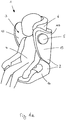
- FIG. 1a shows a child safety seat 1 for transporting a child 4 in a vehicle in accordance with a first embodiment of the invention.
- the child safety seat 1 comprises an outer shell 2 which encloses a seating area 3 for a child 4.
- the outer shell 2 comprises a back rest 103 which comprises side wings 13.
- the outer shell 2 furthermore comprises a base portion 14.
- the child safety seat 1 comprises a head rest 6 which is mounted to the back rest 103.
- the child 4 sits on the base portion 14 and leans against the back rest 103 with the child's 4 head positioned on the head rest 6.
- the side wings 13 are configured to enclose the child's 4 torso on both sides.
- the child safety seat 1 furthermore comprises two protective elements 5 which are mounted to the side wings 13.
- a child safety seat is mounted to one of the seats of the vehicle. Therefore, when installed in a vehicle, a child safety seat is usually positioned in close proximity to one of the doors of the vehicle. In case of a side crash of a vehicle carrying a child safety seat, the child safety seat will therefore usually impact on one of the doors of the vehicle. If this impact is severe, the child sitting in the child safety seat may get injured.
- the protective elements 5 protrude laterally from the outer shell 2, in case of a side crash of the vehicle carrying the child safety seat 1 the protective element 5 facing the nearby door of the vehicle will be the first component of the child safety seat 1 that hits the vehicle. Therefore, the protective elements 5 may be used to control the dynamics of the impact of the child safety seat 1 on the vehicle at a very early stage.
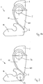
- Figure 1b shows a side view of the child safety seat of Figure 1a .
- This view shows that the protective element 5 covers a large part of the side wing 13. Therefore, forces impacting on the protective element 5 which are transferred from the protective element 5 to the side wing 13 are distributed over a large area of the side wing 13. As a result, the occurrence of high peak forces acting on the side wing 13 can be avoided. This is advantageous since such high peak forces might damage the side wing 13 and result in severe injuries of the child 4.
- Figure 2 shows a side view of a child safety seat 1 in accordance with a second embodiment of the invention.
- This child safety seat 1 differs from the child safety seat of Figures 1a and 1b in that it comprises two protective elements on each side of the child safety seat.
- the child safety seat 1 comprises a first protective element 5a which is mounted to the side wing 13 and a second protective element 5b which is mounted to the base portion 14.
- Figure 2 only shows the left side of the child safety seat 1, therefore only two protective elements are visible.
- Two additional protective elements, which are not visible in Figure 2 are attached to the right side of the child safety seat 1.
- the first protective element 5a and the second protective element 5b constitute two load paths to guide impact forces to the outer shell 2 during a side crash. By providing two load paths the distribution of impact forces across the outer shell 2 can be improved.
- the protective elements 5 of the child safety seat 1 of Figures 1a and 1b and the protective elements 5a and 5b of the child safety seat 1 of Figure 2 are preferably configured to be transferred between a rest position and a functioning position.
- the protective elements are configured to protrude further from the outer shell of the child safety seat when disposed in the functioning position than when disposed in the rest position.
- the protective elements 5, 5a, 5b might be configured to protrude permanently from the outer shell 2 of the child safety seat 1.
- Figure 3 is a partial sectional view of a protective element 5 of a child safety seat in accordance with a preferred embodiment of the invention.
- Figure 3 shows a section of the outer shell 2 of a child safety seat comprising a protective element 5.
- Protective element 5 comprises a housing component 7 and an impact component 8.
- the housing component 7 is embedded into the outer shell 2 of the child safety seat.
- the outer shell 2 comprises an opening which is configured to receive the housing component 7.
- the housing component 7 is cup-shaped and comprises a compressible side wall 10 and a bottom area 101.
- the bottom area 101 is circular.
- the compressible side wall 10 comprises a plurality of apertures 11. In the embodiment of Figure 3 , the apertures 11 are oval holes.
- the apertures 11 are shaped and arranged to allow the housing component 7 to be compressed and to extend in the directions indicated by arrow 16.
- the compressible side wall 10 of the housing component 7 constitutes a deformable region 9.
- the bottom area 101 of the housing component 7 is supported by a fixed bearing 12.
- the housing component furthermore comprises an internal thread 7a.
- the impact component 8 comprises a top portion 8a and a bottom portion 8b.
- the top portion 8a is mounted on top of the bottom portion 8b. As shown in Figure 3 , the top portion 8a is wider in diameter than the bottom portion 8b.
- the top portion 8a is integrally molded with the bottom portion 8b.
- the bottom portion 8b is essentially cylindrical and comprises an external thread 8c.
- the external thread 8c of the impact component 8 is configured to work together with the internal thread 7a of the housing component to build a screw thread. With this screw thread the impact component 8 can be extended from the housing component 7 by rotating the impact component 8 in a first direction and can be retracted into the housing component 7 by rotating the impact component 8 in a second direction opposite to the first direction.
- the first direction is counter-clockwise
- the second direction is clockwise.
- the protective element 5 comprises a stop unit which prevents the impact component 8 from being extracted completely from the housing component 7.
- the stop unit is provided on the impact component 8. The stop unit defines a position of the impact component 8 in which the impact component 8 protrudes maximally from the housing component 7. This position is also referred to as functioning position.
- the impact component 8 can adopt a continuum of intermediate positions between the rest position (fully retracted) and the functioning position (fully extended). Figure 3 shows one of these intermediate positions.
- the impact component 8 will be pushed into the outer shell 2 of the child safety seat.
- a force impacting on the impact position 8 can push the impact component 8 into the outer shell 2.
- compressing the compressible side wall 10 will absorb impact energy and therefore the impact on the child safety seat will be cushioned.
- the impact component 8 can be pushed into the outer shell 2 until the top portion 8a of the impact component 8 contacts the outer shell 2, or until the bottom portion 8b of the impact component 8 hits the bottom area 101 of the housing component 7, or until the compressible side wall 10 of the housing component 7 is completely compressed.
- a force impacting on the impact component 8 will finally be transferred to the child safety seat via the outer shell 2
- the force will finally be transferred to the child safety seat via the fixed bearing 12.
- Figures 4a-d show additional variants of protective elements 5 in accordance with further embodiments of the invention.
- the housing component 7 of the protective element 5 comprises a plurality of triangular apertures 11.
- the housing component 7 of the protective element 5 comprises a plurality of curved apertures 11.
- the housing component 7 of the protective element 5 comprises a plurality of oval apertures 11.
- the oval apertures 11 are arranged in a regular pattern.
- the housing component 7 of the protective element 5 comprises one or more apertures 11 which spiral around the side wall of the housing component 7.
- the side wall 10 of the housing component 7 of the protective element 5 is made compressible by the provision of apertures 11.
- Figure 5 shows a protective element 5 of a child safety seat in accordance with another embodiment of the invention.
- the side wall 111 of the housing component 7 of the protective element 5 is not compressible but rigid.
- the side wall 111 of the housing component 7 does not comprise any apertures.
- the housing component 7 is again embedded into the outer shell 2 of the child safety seat.
- the upper edge of the housing component 7 comprises a flange 112 which rests on the outer shell 2.
- the outer shell 2 is supported by fixed bearings 12.
- the bottom area 101 of the housing component 7 is also supported by a fixed bearing 12.
- the impact component 8 of the protective element 5 is mounted to the housing component 7 as described in the context of Figure 3 .
- the impact component 8 comprises a deformable region 9.
- the deformable region 9 allows the impact component 8 to be compressed and to expand again in the directions indicated by arrow 17.
- the deformable region 9 comprises a foam-like structure comprising thermoplastics or alternative structural elements with damping characteristics.
- the thermoplastics preferably comprise crosslinked polyethylene (XPE), expanded polystyrene (EPS), expanded polypropylene (EPP), or expanded polyethylene (EPE).
- the deformable region 9 of the impact component 8 may also be implemented as described in the context of Figures 3 and 4a-d for the deformable region of the housing component, i.e. the impact component 8 may be made compressible by providing the impact component 8 with apertures.
- the apertures are positioned in a side wall of the bottom portion 8b of the impact component 8.
- the impact component 8 is configured to be transferred between a functioning position and a rest position as described for the impact component 8 of Figure 3 .
- a force acting on the impact component 8 in the direction indicated by arrow 20 will be transferred from the top portion 8a of the impact component 8 via the bottom portion 8b and the external thread 8c to the internal thread 7a of the housing component 7.
- From the internal thread 7a of the housing component 7 a first part of the force will be transferred to the outer shell 2 via the flange 112 of the housing component 7 and from the outer shell 2 to the fixed bearings 12 that support the outer shell 2.
- a second part of the force will be transferred from the internal thread 7a to the bottom area 101 of the housing component 7 via the side wall 111 of the housing component 7 and from the bottom area 101 to the fixed bearing 12 that supports the bottom area 101.
- This flow of forces will result in a compression of the deformable region 9 of the impact component 8. Compressing the deformable region 9 of the impact component 8 will absorb impact energy and therefore the impact on the child safety seat will be cushioned.
- the deformable region 9 of the impact component 8 comprises a plurality of zones of varying compressibility.
- the impact component 8 may comprise a plurality of zones of varying compressibility with each zone exhibiting a constant compressibility and with the compressibility of each zone differing from the compressibility of the other zones.
- the compressibility of a zone correlates with the hardness or rigidity of this zone.
- a highly compressible zone will be softer than a zone which is less compressible.
- the zones of varying compressibility are stacked on top of each other.
- the impact component 8 comprises a topmost compressible zone positioned at or near the top of the impact component 8, a bottommost compressible zone positioned at or near the bottom of the impact component 8, and a plurality of other compressible zones placed between the topmost compressible zone and the bottommost compressible zone.
- the compressibility of the compressible zones increases from top to bottom. Therefore, the topmost compressible zone is preferably more rigid, i.e. less compressible, than the rest of the compressible zones.
- the bottommost compressible zone is preferably softer, i.e. more compressible, than the rest of the compressible zones.
- the compressibility of the impact component 8 might increase from top to bottom stepwise or continually. Preferably, the compressibility of the impact component 8 increases exponentially. With such a compressibility profile of the impact component 8 of the protective element 5 the amount of energy which is absorbed when the impact component 8 is pushed into the outer shell 2 can be kept essentially constant regardless of how far the impact component 8 extends from the outer shell 2.
- the amount of energy which is absorbed when the impact component 8 is pushed into the outer shell 2 is preferably independent of how far the impact component 8 originally protrudes form the outer shell 2. This is particularly advantageous, since in this way it can be ensured that the protective element is always configured to absorb impact energy in a side crash.
- Figure 6 shows a protective element 5 of a child safety seat in accordance with another embodiment of the invention. In many aspects, this embodiment is similar to the embodiment of Figure 5 .
- the side wall 111 of the housing component 7 of the protective element 5 is not compressible but rigid and the upper edge of the housing component 7 comprises a flange 112 which rests on the outer shell 2.
- the protective element 5 of Figure 6 differs from the protective element 5 of Figure 5 mainly in the way the impact component 8 is mounted to the housing component 7.
- the impact component 8 is configured to be pushed into the housing component by a force acting on the impact component 8 in the direction of arrow 20.
- the external thread 8c of the impact component 8 and the internal thread 7a of the housing component 7 are designed to allow the ridges of the external thread 8c to be pushed past the ridges of the internal thread 7a. Therefore, when the impact component 8 is pushed into the housing component 7 the bottom portion 8b of the impact component 8 will be compressed laterally and expand again repeatedly. Laterally compressing the bottom portion 8b of the impact component 8 will absorb impact energy and therefore the impact on the child safety seat will be cushioned as the impact component 8 is pushed into the housing component 7. Generally, the impact component 8 will not be pushed into the housing component 7 at a constant speed but will be pushed in in steps instead. This stepwise movement is indicated by arrows 18 in Figure 6 .
- the protective element 5 may comprise a catch mechanism to connect the impact component 8 to the housing component 7.
- This catch mechanism preferably allows the impact component 8 to be pushed into and to be pulled out of the housing component 7.
- the bottom portion 8b of the impact component 8 comprises a plurality of circular grooves instead of the external thread 8c.
- the housing component 7 preferably comprises a circular ridge instead of the internal thread 7a. The circular ridge is configured to mesh with the circular grooves of the impact component 8. Rotating the impact component 8 about its central axis will then not result in transfer of the impact component 8 between the rest position and the functioning position.
- the impact component 8 has to be pushed into the housing component 7 or be pulled out of the housing component 7.
- the cross-section of the protective element 5 can then be freely designed. In particular, it is possible to adapt the shape of the protective element 5 to the shape of the child safety seat.
- the shape of the protective element 5 could be adapted to the shape of the base portion and, for a protective element 5 attached to the side wing of a child safety seat, the shape of the protective element 5 could be adapted to the shape of the side wing.
- Figure 7 shows a protective element 5 of a child safety seat in accordance with another embodiment of the invention.
- the upper edge of the housing component 7 again comprises a flange 112 which rests on the outer shell 2.
- the outer shell 2 is configured to be resilient or elastic in the vicinity of the protective element 5.
- the child safety seat comprises elastic elements 15 which couple the outer shell 2 to fixed bearings 12. When the section of the outer shell 2 shown in Figure 7 is pushed downwards towards the fixed bearings 12, the elastic elements 15 are being compressed. When the force on the outer shell 2 is reduced, the elastic elements 15 will push the outer shell 2 back towards its original position. This is indicated by arrow 19 in Figure 7 .
- the outer shell 2 itself could be configured to exhibit a high degree of resilience. Then the outer shell 2 will by itself return to its original position after it has been pushed downwards.
- a force acting on the impact component 8 in the direction of arrow 20 will be transferred from the top portion 8a of the impact component 8 to the bottom portion 8b of the impact component 8 and from the bottom portion 8b to the outer shell 2 via the external thread 8c, the internal thread 7a, and the flange 112.
- the impact component 8, the housing component 7, and the outer shell 2 will be pushed downwards, deforming the outer shell 2 and compressing the elastic elements 15. Deforming the outer shell 2 and compressing the elastic elements 15 will absorb impact energy and therefore the impact on the child safety seat will be cushioned. Since in this embodiment of the invention there is no flow of forces along the side wall and the bottom area of the housing component 7, side wall and bottom area might be omitted.
- the resulting housing component is preferably ring-shaped and is advantageously integrally formed with the outer shell 2.
- the impact component 8 might advantageously comprise a deformable region as described for the impact component of Figure 5 .
- the screw thread comprising an external thread and an internal thread might be replaced by a catch mechanism as described for the protective element of Figure 6 .
- the outer shell might comprise a resilient region as described for the impact component of Figure 7 . The resulting protective element will be particularly suitable for cushioning impact forces acting on a child safety seat.
Landscapes
- Engineering & Computer Science (AREA)
- Mechanical Engineering (AREA)
- Aviation & Aerospace Engineering (AREA)
- Transportation (AREA)
- Health & Medical Sciences (AREA)
- Child & Adolescent Psychology (AREA)
- General Health & Medical Sciences (AREA)
- Seats For Vehicles (AREA)
Claims (13)
- Siège de sécurité enfant (1) destiné un véhicule comprenant- une coque extérieure (2) renfermant une zone d'assise (3) pour un enfant (4) et- un élément de protection (5),l'élément de protection (5) comprenant- un composant de boîtier (7) et- un composant de réception d'impact (8), oùle composant de boîtier (7) est incorporé dans la coque extérieure (2) et le composant de réception d'impact (8)
est monté contre le composant de boîtier (7),
est configuré pour être renfermé au moins partiellement par le composant de boîtier (7), et
est configuré pour être en saillie latéralement par rapport à la coque extérieure (2) dans une direction face à face avec la zone d'assise (3), le composant de réception d'impact de l'élément de protection étant configuré pour être transféré d'une position de repos vers une position de fonction, et le composant de réception d'impact de l'élément de protection étant configuré pour être en saillie éloigné par rapport à la coque extérieure lorsqu'il est disposé dans la position de fonction que lorsqu'il est disposé dans la position de repos,
le composant de boîtier (7) ou le composant de réception d'impact (8) comprenant une région déformable (9) adaptée à amortir des forces ayant un effet sur le composant de réception d'impact (8),
caractérisé par
le fait que le composant de boîtier (7) est porté par un support fixe (12), le support fixe permettant aux forces d'impact d'être guidées dans une partie structurellement stable du siège de sécurité enfant,
le composant de réception d'impact (8) comprenant une partie supérieure (8a) et une partie de base (8b), la partie supérieure étant montée sur le dessus de la partie de base et la partie supérieure étant plus large en diamètre que la partie de base, le bord extérieur de la partie supérieure reposant sur la coque extérieure (2) lorsque le composant de réception d'impact est rétracté complètement à l'intérieur du composant de boîtier (7). - Siège de sécurité enfant (1) selon la revendication 1, dans lequel le composant de réception d'impact (8) comprend une région déformable (9) adaptée pour amortir des forces ayant un effet sur le composant de réception d'impact (8) et dans lequel la région déformable (9) comprend une pluralité de zones de compressibilité variable.
- Siège de sécurité enfant (1) selon la revendication 1 ou 2, dans lequel la région déformable (9) comprend une structure semblable à de la mousse.
- Siège de sécurité enfant (1) selon l'une quelconque des revendications précédentes, dans lequel le composant de boîtier (7) comprend une paroi latérale compressible (10).
- Siège de sécurité enfant (1) selon la revendication 4, dans lequel la paroi latérale compressible (10) comprend des ouvertures (11).
- Siège de sécurité enfant (1) selon l'une quelconque des revendications précédentes, dans lequel le composant de réception d'impact (8) et le composant de boîtier (7) sont configurés pour réaliser un amortissement de forces ayant un effet sur le composant de réception d'impact (8) en transférant le composant de réception d'impact (8) de la position de fonction vers la position de repos.
- Siège de sécurité enfant (1) selon l'une quelconque des revendications précédentes, dans lequel la coque extérieure (2) comprend une aile latérale (13) et le composant de boîtier (7) est incorporé dans l'aile latérale (13).
- Siège de sécurité enfant (1) selon l'une quelconque des revendications précédentes, dans lequel la coque extérieure (2) comprend une partie de base (14), et le composant de boîtier (7) est incorporé dans la partie de base (14).
- Siège de sécurité enfant (1) selon l'une quelconque des revendications précédentes, dans lequel le composant de boîtier (7) est intégralement formé avec la coque extérieure (2).
- Siège de sécurité enfant (1) selon l'une quelconque des revendications précédentes, dans lequel le composant de réception d'impact (8) comprend un corps rigide moulé à partir d'un matériau thermoplastique.
- Siège de sécurité enfant (1) selon la revendication 10, dans lequel le corps rigide comprend un filetage de vis (8c).
- Siège de sécurité enfant (1) selon l'une quelconque des revendications précédentes, dans lequel le composant de boîtier (7) comprend une bride (112) configurée pour reposer sur la coque extérieure (2).
- Siège de sécurité enfant (1) selon l'une quelconque des revendications précédentes, dans lequel au moins deux éléments de protection (5) sont montés au niveau de chaque côté du siège de sécurité enfant (1) avec, sur chaque côté, au moins un élément de protection (5) positionné dans la moitié supérieure du siège de sécurité enfant (1) et un autre élément de protection (5) positionné dans la moitié inférieure du siège de sécurité enfant (1).
Priority Applications (24)
| Application Number | Priority Date | Filing Date | Title |
|---|---|---|---|
| EP18187669.9A EP3437923B1 (fr) | 2013-07-16 | 2013-07-16 | Siège de sécurité enfant |
| ES18187668T ES2868240T3 (es) | 2013-07-16 | 2013-07-16 | Asiento de seguridad para niños |
| ES21157290T ES2945860T3 (es) | 2013-07-16 | 2013-07-16 | Asiento de seguridad para niños |
| EP21157290.4A EP3858663B1 (fr) | 2013-07-16 | 2013-07-16 | Siège de sécurité enfant |
| TR2018/15537T TR201815537T4 (tr) | 2013-07-16 | 2013-07-16 | Çocuk güvenlik koltuğu. |
| ES18187669T ES2868241T3 (es) | 2013-07-16 | 2013-07-16 | Asiento de seguridad para niños |
| EP18187668.1A EP3437922B1 (fr) | 2013-07-16 | 2013-07-16 | Siège de sécurité enfant |
| EP18187663.2A EP3437920B1 (fr) | 2013-07-16 | 2013-07-16 | Siège de sécurité enfant |
| ES18187666T ES2867533T3 (es) | 2013-07-16 | 2013-07-16 | Asiento de seguridad para niños |
| EP18187666.5A EP3437921B1 (fr) | 2013-07-16 | 2013-07-16 | Siège de sécurité enfant |
| EP13003568.6A EP2826662B1 (fr) | 2013-07-16 | 2013-07-16 | Siège de sécurité enfant |
| ES18187663T ES2868238T3 (es) | 2013-07-16 | 2013-07-16 | Asiento de seguridad para niños |
| ES13003568.6T ES2692540T3 (es) | 2013-07-16 | 2013-07-16 | Asiento de seguridad para niños |
| JP2016526465A JP6293881B2 (ja) | 2013-07-16 | 2014-07-07 | 安全チャイルドシート |
| CN202010959456.6A CN112092692B (zh) | 2013-07-16 | 2014-07-07 | 儿童安全座椅 |
| KR1020167001237A KR101857533B1 (ko) | 2013-07-16 | 2014-07-07 | 아동용 안전 시트 |
| CA2915515A CA2915515C (fr) | 2013-07-16 | 2014-07-07 | Siege de securite pour enfant |
| CN201480040381.4A CN105377625B (zh) | 2013-07-16 | 2014-07-07 | 儿童安全座椅 |
| AU2014292483A AU2014292483C1 (en) | 2013-07-16 | 2014-07-07 | Child safety seat |
| US14/904,271 US9908444B2 (en) | 2013-07-16 | 2014-07-07 | Child safety seat |
| RU2016104919A RU2657660C2 (ru) | 2013-07-16 | 2014-07-07 | Детское автомобильное кресло |
| PCT/EP2014/001859 WO2015007372A1 (fr) | 2013-07-16 | 2014-07-07 | Siège de sécurité pour enfant |
| ARP140102613A AR096925A1 (es) | 2013-07-16 | 2014-07-15 | Asiento de seguridad para niños |
| IL248666A IL248666B (en) | 2013-07-16 | 2016-11-01 | Safety chair for children |
Applications Claiming Priority (1)
| Application Number | Priority Date | Filing Date | Title |
|---|---|---|---|
| EP13003568.6A EP2826662B1 (fr) | 2013-07-16 | 2013-07-16 | Siège de sécurité enfant |
Related Child Applications (9)
| Application Number | Title | Priority Date | Filing Date |
|---|---|---|---|
| EP18187666.5A Division EP3437921B1 (fr) | 2013-07-16 | 2013-07-16 | Siège de sécurité enfant |
| EP18187666.5A Division-Into EP3437921B1 (fr) | 2013-07-16 | 2013-07-16 | Siège de sécurité enfant |
| EP21157290.4A Division EP3858663B1 (fr) | 2013-07-16 | 2013-07-16 | Siège de sécurité enfant |
| EP18187663.2A Division-Into EP3437920B1 (fr) | 2013-07-16 | 2013-07-16 | Siège de sécurité enfant |
| EP18187663.2A Division EP3437920B1 (fr) | 2013-07-16 | 2013-07-16 | Siège de sécurité enfant |
| EP18187669.9A Division-Into EP3437923B1 (fr) | 2013-07-16 | 2013-07-16 | Siège de sécurité enfant |
| EP18187669.9A Division EP3437923B1 (fr) | 2013-07-16 | 2013-07-16 | Siège de sécurité enfant |
| EP18187668.1A Division-Into EP3437922B1 (fr) | 2013-07-16 | 2013-07-16 | Siège de sécurité enfant |
| EP18187668.1A Division EP3437922B1 (fr) | 2013-07-16 | 2013-07-16 | Siège de sécurité enfant |
Publications (2)
| Publication Number | Publication Date |
|---|---|
| EP2826662A1 EP2826662A1 (fr) | 2015-01-21 |
| EP2826662B1 true EP2826662B1 (fr) | 2018-09-19 |
Family
ID=48793861
Family Applications (6)
| Application Number | Title | Priority Date | Filing Date |
|---|---|---|---|
| EP13003568.6A Active EP2826662B1 (fr) | 2013-07-16 | 2013-07-16 | Siège de sécurité enfant |
| EP21157290.4A Active EP3858663B1 (fr) | 2013-07-16 | 2013-07-16 | Siège de sécurité enfant |
| EP18187666.5A Active EP3437921B1 (fr) | 2013-07-16 | 2013-07-16 | Siège de sécurité enfant |
| EP18187663.2A Active EP3437920B1 (fr) | 2013-07-16 | 2013-07-16 | Siège de sécurité enfant |
| EP18187669.9A Active EP3437923B1 (fr) | 2013-07-16 | 2013-07-16 | Siège de sécurité enfant |
| EP18187668.1A Active EP3437922B1 (fr) | 2013-07-16 | 2013-07-16 | Siège de sécurité enfant |
Family Applications After (5)
| Application Number | Title | Priority Date | Filing Date |
|---|---|---|---|
| EP21157290.4A Active EP3858663B1 (fr) | 2013-07-16 | 2013-07-16 | Siège de sécurité enfant |
| EP18187666.5A Active EP3437921B1 (fr) | 2013-07-16 | 2013-07-16 | Siège de sécurité enfant |
| EP18187663.2A Active EP3437920B1 (fr) | 2013-07-16 | 2013-07-16 | Siège de sécurité enfant |
| EP18187669.9A Active EP3437923B1 (fr) | 2013-07-16 | 2013-07-16 | Siège de sécurité enfant |
| EP18187668.1A Active EP3437922B1 (fr) | 2013-07-16 | 2013-07-16 | Siège de sécurité enfant |
Country Status (13)
| Country | Link |
|---|---|
| US (1) | US9908444B2 (fr) |
| EP (6) | EP2826662B1 (fr) |
| JP (1) | JP6293881B2 (fr) |
| KR (1) | KR101857533B1 (fr) |
| CN (2) | CN105377625B (fr) |
| AR (1) | AR096925A1 (fr) |
| AU (1) | AU2014292483C1 (fr) |
| CA (1) | CA2915515C (fr) |
| ES (6) | ES2692540T3 (fr) |
| IL (1) | IL248666B (fr) |
| RU (1) | RU2657660C2 (fr) |
| TR (1) | TR201815537T4 (fr) |
| WO (1) | WO2015007372A1 (fr) |
Cited By (1)
| Publication number | Priority date | Publication date | Assignee | Title |
|---|---|---|---|---|
| EP4382358A3 (fr) * | 2019-07-18 | 2024-10-16 | Wonderland Switzerland AG | Siège de sécurité pour enfant |
Families Citing this family (28)
| Publication number | Priority date | Publication date | Assignee | Title |
|---|---|---|---|---|
| CN105329121B (zh) | 2014-08-06 | 2018-06-12 | 宝钜儿童用品香港股份有限公司 | 侧撞保护机构及儿童安全座椅 |
| US20170349132A1 (en) * | 2014-12-22 | 2017-12-07 | Emma Garatea | Inflatable protection for a child seat |
| CA2930939C (fr) * | 2015-05-27 | 2019-02-26 | Wonderland Nurserygoods Company Limited | Siege de securite pour enfant et base de soutien associee |
| AU2017279736B2 (en) * | 2016-12-23 | 2023-12-14 | Britax Childcare Pty Ltd | Impact energy absorbing device |
| USD836354S1 (en) * | 2017-01-06 | 2018-12-25 | OSIM International Pte Ltd | Massage chair |
| KR101880867B1 (ko) * | 2017-12-22 | 2018-07-20 | 주식회사 다이치 | 카시트의 충격 흡수장치 |
| EP3882073B1 (fr) * | 2018-01-24 | 2024-03-06 | BRITAX RÖMER Kindersicherheit GmbH | Élément de protection extensible destiné à être utilisé dans un siège de sécurité pour enfant |
| CN108437860B (zh) * | 2018-03-13 | 2023-10-31 | 麦克英孚(宁波)婴童用品有限公司 | 一种侧面保护机构 |
| CA3047971C (fr) * | 2018-07-05 | 2023-06-27 | Britax Child Safety, Inc. | Brise-charge multifonctionnelle |
| CN108859884B (zh) * | 2018-07-16 | 2024-08-16 | 麦克英孚(宁波)婴童用品有限公司 | 一种角度无级调节机构以及儿童安全座椅 |
| NO344434B1 (en) * | 2018-09-19 | 2019-12-09 | Torgersen Hans & Soenn | Child safety seat with side impact energy absorption |
| CN111845483B (zh) * | 2019-04-29 | 2023-09-12 | 明门瑞士股份有限公司 | 侧撞保护装置及儿童安全座椅 |
| US11318867B2 (en) * | 2019-09-16 | 2022-05-03 | Monahan Products, LLC | Child carrier with side impact protection |
| CN110576769B (zh) * | 2019-09-18 | 2024-03-19 | 江苏安用座椅科技有限公司 | 一种儿童安全座椅侧边防护缓冲装置及其组装、使用方法 |
| CN113386639A (zh) | 2020-03-13 | 2021-09-14 | 宝钜瑞士股份有限公司 | 儿童安全座椅 |
| CN113815502B (zh) | 2020-06-19 | 2024-07-26 | 宝钜瑞士股份有限公司 | 儿童安全座椅及其侧撞保护机构 |
| CN113859065B (zh) | 2020-06-30 | 2024-07-09 | 宝钜瑞士股份有限公司 | 儿童安全座椅及其侧撞保护机构 |
| CN118906932A (zh) * | 2020-07-06 | 2024-11-08 | 宝钜瑞士股份有限公司 | 儿童安全座椅 |
| US11511656B2 (en) * | 2021-03-24 | 2022-11-29 | Monahan Products, LLC | Child restraint system with side impact bumper |
| CN119099446A (zh) | 2021-04-21 | 2024-12-10 | 宝钜瑞士股份有限公司 | 侧撞保护块、安装座和儿童安全座椅 |
| US12162387B2 (en) | 2021-06-25 | 2024-12-10 | Dorel Juvenile Group, Inc. | Child restraint |
| US12012020B2 (en) * | 2022-07-14 | 2024-06-18 | Ford Global Technologies, Llc | Child seat anchor including energy absorber |
| US12472854B2 (en) | 2022-09-26 | 2025-11-18 | Dorel Juvenile Group, Inc. | Child restraint |
| US12515568B2 (en) | 2022-09-26 | 2026-01-06 | Dorel Juvenile Group, Inc. | Child restraint |
| CN220884147U (zh) * | 2023-09-27 | 2024-05-03 | 麦克英孚(宁波)婴童用品有限公司 | 侧撞缓冲机构和儿童安全座椅 |
| WO2025072394A1 (fr) * | 2023-09-28 | 2025-04-03 | Wonderland Switzerland Ag | Protection contre les chocs latéraux sur un siège de voiture |
| WO2025141806A1 (fr) * | 2023-12-27 | 2025-07-03 | コンビ株式会社 | Siège auto pour enfant |
| US20250262995A1 (en) | 2024-02-20 | 2025-08-21 | Britax Child Safety, Inc. | Car seat with adjustable side impact protection and adjustable self-deploying inner arm rests |
Citations (10)
| Publication number | Priority date | Publication date | Assignee | Title |
|---|---|---|---|---|
| US20090152913A1 (en) | 2007-12-12 | 2009-06-18 | Britax Child Safety, Inc. | Child restraint apparatus for vehicle |
| US20100026064A1 (en) | 2008-07-30 | 2010-02-04 | Cosco Management, Inc. | Energy-dissipation system |
| US20100295345A1 (en) | 2009-05-20 | 2010-11-25 | Cosco Management, Inc. | Energy-dissipation system |
| EP2275303A1 (fr) | 2009-07-14 | 2011-01-19 | BRITAX RÖMER Kindersicherheit GmbH | Siège pour enfants doté d'une protection contre les chocs latéraux |
| WO2011054063A1 (fr) | 2009-11-09 | 2011-05-12 | Britax Childcare Pty Ltd | Siège pour enfant offrant une protection contre les chocs |
| US8061768B2 (en) | 2008-07-30 | 2011-11-22 | Cosco Management, Inc. | Energy-dissipation system |
| DE202012102471U1 (de) | 2012-06-18 | 2012-09-07 | Cybex Gmbh | Kindersitz zur Anbringung auf einem Kraftfahrzeugsitz |
| US20120242129A1 (en) | 2011-03-22 | 2012-09-27 | Cosco Management, Inc. | Infant holder for vehicle seat |
| EP2570299A1 (fr) | 2011-09-13 | 2013-03-20 | Britax Römer Kindersicherheit GmbH | Siège de sécurité pour enfants pour véhicules |
| EP2746097A1 (fr) | 2012-12-21 | 2014-06-25 | Britax Childcare Pty Ltd. | Protection contre les chocs latéraux mécaniques pour dispositif de sécurité pour enfant |
Family Cites Families (18)
| Publication number | Priority date | Publication date | Assignee | Title |
|---|---|---|---|---|
| JP3150912B2 (ja) * | 1996-09-25 | 2001-03-26 | コンビ株式会社 | 高通気性チャイルドシート |
| JP2000142194A (ja) * | 1998-01-27 | 2000-05-23 | Aprica Kassai Inc | 育児器具 |
| US6142563A (en) * | 1998-10-09 | 2000-11-07 | Joalto Design | Vehicle seat with energy absorbing deformable structural material |
| DE19952777C1 (de) | 1999-11-03 | 2000-12-07 | Daimler Chrysler Ag | Personenkraftwagen |
| US7232182B2 (en) * | 2003-02-25 | 2007-06-19 | Takata Corporation | Child seat |
| JP2004314800A (ja) * | 2003-04-16 | 2004-11-11 | Takata Corp | チャイルドシート |
| US7125073B2 (en) * | 2003-02-25 | 2006-10-24 | Takata Corporation | Child seat |
| JP2005001541A (ja) * | 2003-06-12 | 2005-01-06 | Takata Corp | チャイルドシート |
| KR100554019B1 (ko) | 2004-08-17 | 2006-02-22 | 현대모비스 주식회사 | 차체의 횡강성 보강장치 |
| US7387327B2 (en) * | 2005-06-24 | 2008-06-17 | University Of Washington | Structure and system for occupant protection in a side impact automobile collision and methods of use thereof |
| DE102005062849A1 (de) * | 2005-12-23 | 2007-09-06 | Takata-Petri Ag | Insassenrückhalteeinrichtung für ein Kraftfahrzeug |
| ES1065298Y (es) * | 2007-04-23 | 2007-10-16 | Jane Sa | Dispositivo de seguridad ante colisiones, aplicable a asientos infantiles |
| US8056972B2 (en) * | 2009-05-20 | 2011-11-15 | Cosco Management, Inc. | Energy-dissipation system |
| US8128165B2 (en) * | 2009-05-20 | 2012-03-06 | Cosco Management, Inc. | Energy-dissipation system |
| US8052210B2 (en) * | 2009-05-20 | 2011-11-08 | Cosco Management, Inc. | Energy-dissipation system |
| US8096613B2 (en) * | 2009-07-15 | 2012-01-17 | Meeker R&D | Head retaining foam liner for car seat |
| US9211820B2 (en) * | 2012-11-01 | 2015-12-15 | Graco Children's Products Inc. | Child safety seat with side impact energy redirection |
| CN203032420U (zh) * | 2013-01-05 | 2013-07-03 | 好孩子儿童用品有限公司 | 具有侧向防撞系统的儿童座椅 |
-
2013
- 2013-07-16 EP EP13003568.6A patent/EP2826662B1/fr active Active
- 2013-07-16 EP EP21157290.4A patent/EP3858663B1/fr active Active
- 2013-07-16 EP EP18187666.5A patent/EP3437921B1/fr active Active
- 2013-07-16 ES ES13003568.6T patent/ES2692540T3/es active Active
- 2013-07-16 ES ES18187666T patent/ES2867533T3/es active Active
- 2013-07-16 ES ES18187669T patent/ES2868241T3/es active Active
- 2013-07-16 EP EP18187663.2A patent/EP3437920B1/fr active Active
- 2013-07-16 EP EP18187669.9A patent/EP3437923B1/fr active Active
- 2013-07-16 EP EP18187668.1A patent/EP3437922B1/fr active Active
- 2013-07-16 TR TR2018/15537T patent/TR201815537T4/tr unknown
- 2013-07-16 ES ES18187663T patent/ES2868238T3/es active Active
- 2013-07-16 ES ES21157290T patent/ES2945860T3/es active Active
- 2013-07-16 ES ES18187668T patent/ES2868240T3/es active Active
-
2014
- 2014-07-07 CN CN201480040381.4A patent/CN105377625B/zh active Active
- 2014-07-07 KR KR1020167001237A patent/KR101857533B1/ko active Active
- 2014-07-07 WO PCT/EP2014/001859 patent/WO2015007372A1/fr not_active Ceased
- 2014-07-07 RU RU2016104919A patent/RU2657660C2/ru active
- 2014-07-07 CA CA2915515A patent/CA2915515C/fr active Active
- 2014-07-07 US US14/904,271 patent/US9908444B2/en active Active
- 2014-07-07 AU AU2014292483A patent/AU2014292483C1/en active Active
- 2014-07-07 CN CN202010959456.6A patent/CN112092692B/zh active Active
- 2014-07-07 JP JP2016526465A patent/JP6293881B2/ja not_active Expired - Fee Related
- 2014-07-15 AR ARP140102613A patent/AR096925A1/es active IP Right Grant
-
2016
- 2016-11-01 IL IL248666A patent/IL248666B/en active IP Right Grant
Patent Citations (10)
| Publication number | Priority date | Publication date | Assignee | Title |
|---|---|---|---|---|
| US20090152913A1 (en) | 2007-12-12 | 2009-06-18 | Britax Child Safety, Inc. | Child restraint apparatus for vehicle |
| US20100026064A1 (en) | 2008-07-30 | 2010-02-04 | Cosco Management, Inc. | Energy-dissipation system |
| US8061768B2 (en) | 2008-07-30 | 2011-11-22 | Cosco Management, Inc. | Energy-dissipation system |
| US20100295345A1 (en) | 2009-05-20 | 2010-11-25 | Cosco Management, Inc. | Energy-dissipation system |
| EP2275303A1 (fr) | 2009-07-14 | 2011-01-19 | BRITAX RÖMER Kindersicherheit GmbH | Siège pour enfants doté d'une protection contre les chocs latéraux |
| WO2011054063A1 (fr) | 2009-11-09 | 2011-05-12 | Britax Childcare Pty Ltd | Siège pour enfant offrant une protection contre les chocs |
| US20120242129A1 (en) | 2011-03-22 | 2012-09-27 | Cosco Management, Inc. | Infant holder for vehicle seat |
| EP2570299A1 (fr) | 2011-09-13 | 2013-03-20 | Britax Römer Kindersicherheit GmbH | Siège de sécurité pour enfants pour véhicules |
| DE202012102471U1 (de) | 2012-06-18 | 2012-09-07 | Cybex Gmbh | Kindersitz zur Anbringung auf einem Kraftfahrzeugsitz |
| EP2746097A1 (fr) | 2012-12-21 | 2014-06-25 | Britax Childcare Pty Ltd. | Protection contre les chocs latéraux mécaniques pour dispositif de sécurité pour enfant |
Non-Patent Citations (8)
| Title |
|---|
| ANONYMOUS: "Bayreuther Firma CYBEX gewinnt zwei Red Dot Design Awards", DER NEUE WIESENTBOTE, 25 March 2014 (2014-03-25), XP055619042, Retrieved from the Internet <URL:https://www.wiesentbote.de/2014/03/25/bayreuther-firma-cybex-gewinnt-zwei-red-dot-design-awards/> |
| ANONYMOUS: "Eine Revolutionäre Perspektive", CYBEX GMBH, 2012, XP055619066 |
| ANONYMOUS: "Innovation Awards 2012 verliehen", PRESSEMITTEILUNG KIND+JUGEND, 13 September 2012 (2012-09-13), XP055619038 |
| ANONYMOUS: "Kleinkinder sitzen rückwärts sicherer", AUTOBILD.DE, 30 November 2012 (2012-11-30), XP055619021, Retrieved from the Internet <URL:https://www.autobild.de/artikel/kindersitze-reboard-3734614.html> |
| ANONYMOUS: "Mehr Rückhalt fürs Kind", TEST, June 2013 (2013-06-01), pages 79 - 82, XP055619017 |
| ANONYMOUS: "Sirona", CYBEX GMBH, pages 1 - 33 |
| SANDRA: "Cybex Sirona – Wir fahren rückwärts! (Teil 1) / Sandra's Testblog", INTERNET ARCHIVE WAYBACK MACHINE, 16 January 2013 (2013-01-16), XP055619053, Retrieved from the Internet <URL:https://web.archive.org/web/20130116071007/http://www.sandras-testblog.de/cybex-sirona-wir-fahren-rueckwaerts-9400/> |
| SANDRA: "Cybex Sirona – Wir fahren rückwärts! (Teil 2 – die Praxis) / Sandra's Testblog", INTERNET ARCHIVE WAYBACK MACHINE, 19 January 2013 (2013-01-19), XP055619061, Retrieved from the Internet <URL:https://web.archive.org/web/20130119024003/http://www.sandras-testblog.de/cybex-sirona-wir-fahren-rueckwaerts-teil-2-die-praxis-9667> |
Cited By (1)
| Publication number | Priority date | Publication date | Assignee | Title |
|---|---|---|---|---|
| EP4382358A3 (fr) * | 2019-07-18 | 2024-10-16 | Wonderland Switzerland AG | Siège de sécurité pour enfant |
Also Published As
Similar Documents
| Publication | Publication Date | Title |
|---|---|---|
| EP3437922B1 (fr) | Siège de sécurité enfant | |
| CN103072497B (zh) | 车辆用儿童安全座椅及提高乘客安全的方法 | |
| CN107921892B (zh) | 儿童座椅保护装置 | |
| US8950735B2 (en) | Shock absorbers for protective body gear | |
| CN111683836B (zh) | 用于安装在机动车座椅上的儿童座椅 | |
| EP2868945B1 (fr) | Absorbeurs de chocs pour équipement protecteur | |
| EP4329552A1 (fr) | Structure d'absorption d'impact | |
| EP3334951B1 (fr) | Amortisseurs pour dispositifs de protection corporelle | |
| CN119389083B (zh) | 抗坠毁座椅组件及车辆 | |
| CA2829631C (fr) | Amortisseurs pour equipement de protection corporelle |
Legal Events
| Date | Code | Title | Description |
|---|---|---|---|
| 17P | Request for examination filed |
Effective date: 20130716 |
|
| AK | Designated contracting states |
Kind code of ref document: A1 Designated state(s): AL AT BE BG CH CY CZ DE DK EE ES FI FR GB GR HR HU IE IS IT LI LT LU LV MC MK MT NL NO PL PT RO RS SE SI SK SM TR |
|
| AX | Request for extension of the european patent |
Extension state: BA ME |
|
| PUAI | Public reference made under article 153(3) epc to a published international application that has entered the european phase |
Free format text: ORIGINAL CODE: 0009012 |
|
| R17P | Request for examination filed (corrected) |
Effective date: 20150625 |
|
| RBV | Designated contracting states (corrected) |
Designated state(s): AL AT BE BG CH CY CZ DE DK EE ES FI FR GB GR HR HU IE IS IT LI LT LU LV MC MK MT NL NO PL PT RO RS SE SI SK SM TR |
|
| STAA | Information on the status of an ep patent application or granted ep patent |
Free format text: STATUS: EXAMINATION IS IN PROGRESS |
|
| 17Q | First examination report despatched |
Effective date: 20180126 |
|
| GRAP | Despatch of communication of intention to grant a patent |
Free format text: ORIGINAL CODE: EPIDOSNIGR1 |
|
| STAA | Information on the status of an ep patent application or granted ep patent |
Free format text: STATUS: GRANT OF PATENT IS INTENDED |
|
| INTG | Intention to grant announced |
Effective date: 20180627 |
|
| GRAS | Grant fee paid |
Free format text: ORIGINAL CODE: EPIDOSNIGR3 |
|
| GRAA | (expected) grant |
Free format text: ORIGINAL CODE: 0009210 |
|
| STAA | Information on the status of an ep patent application or granted ep patent |
Free format text: STATUS: THE PATENT HAS BEEN GRANTED |
|
| AK | Designated contracting states |
Kind code of ref document: B1 Designated state(s): AL AT BE BG CH CY CZ DE DK EE ES FI FR GB GR HR HU IE IS IT LI LT LU LV MC MK MT NL NO PL PT RO RS SE SI SK SM TR |
|
| REG | Reference to a national code |
Ref country code: GB Ref legal event code: FG4D |
|
| REG | Reference to a national code |
Ref country code: CH Ref legal event code: EP |
|
| REG | Reference to a national code |
Ref country code: DE Ref legal event code: R096 Ref document number: 602013043755 Country of ref document: DE |
|
| REG | Reference to a national code |
Ref country code: AT Ref legal event code: REF Ref document number: 1042868 Country of ref document: AT Kind code of ref document: T Effective date: 20181015 |
|
| REG | Reference to a national code |
Ref country code: IE Ref legal event code: FG4D |
|
| REG | Reference to a national code |
Ref country code: SE Ref legal event code: TRGR |
|
| REG | Reference to a national code |
Ref country code: ES Ref legal event code: FG2A Ref document number: 2692540 Country of ref document: ES Kind code of ref document: T3 Effective date: 20181204 |
|
| REG | Reference to a national code |
Ref country code: NL Ref legal event code: MP Effective date: 20180919 |
|
| PG25 | Lapsed in a contracting state [announced via postgrant information from national office to epo] |
Ref country code: BG Free format text: LAPSE BECAUSE OF FAILURE TO SUBMIT A TRANSLATION OF THE DESCRIPTION OR TO PAY THE FEE WITHIN THE PRESCRIBED TIME-LIMIT Effective date: 20181219 Ref country code: GR Free format text: LAPSE BECAUSE OF FAILURE TO SUBMIT A TRANSLATION OF THE DESCRIPTION OR TO PAY THE FEE WITHIN THE PRESCRIBED TIME-LIMIT Effective date: 20181220 Ref country code: LT Free format text: LAPSE BECAUSE OF FAILURE TO SUBMIT A TRANSLATION OF THE DESCRIPTION OR TO PAY THE FEE WITHIN THE PRESCRIBED TIME-LIMIT Effective date: 20180919 Ref country code: NO Free format text: LAPSE BECAUSE OF FAILURE TO SUBMIT A TRANSLATION OF THE DESCRIPTION OR TO PAY THE FEE WITHIN THE PRESCRIBED TIME-LIMIT Effective date: 20181219 Ref country code: RS Free format text: LAPSE BECAUSE OF FAILURE TO SUBMIT A TRANSLATION OF THE DESCRIPTION OR TO PAY THE FEE WITHIN THE PRESCRIBED TIME-LIMIT Effective date: 20180919 Ref country code: FI Free format text: LAPSE BECAUSE OF FAILURE TO SUBMIT A TRANSLATION OF THE DESCRIPTION OR TO PAY THE FEE WITHIN THE PRESCRIBED TIME-LIMIT Effective date: 20180919 |
|
| REG | Reference to a national code |
Ref country code: LT Ref legal event code: MG4D |
|
| PG25 | Lapsed in a contracting state [announced via postgrant information from national office to epo] |
Ref country code: HR Free format text: LAPSE BECAUSE OF FAILURE TO SUBMIT A TRANSLATION OF THE DESCRIPTION OR TO PAY THE FEE WITHIN THE PRESCRIBED TIME-LIMIT Effective date: 20180919 Ref country code: AL Free format text: LAPSE BECAUSE OF FAILURE TO SUBMIT A TRANSLATION OF THE DESCRIPTION OR TO PAY THE FEE WITHIN THE PRESCRIBED TIME-LIMIT Effective date: 20180919 Ref country code: LV Free format text: LAPSE BECAUSE OF FAILURE TO SUBMIT A TRANSLATION OF THE DESCRIPTION OR TO PAY THE FEE WITHIN THE PRESCRIBED TIME-LIMIT Effective date: 20180919 |
|
| REG | Reference to a national code |
Ref country code: AT Ref legal event code: MK05 Ref document number: 1042868 Country of ref document: AT Kind code of ref document: T Effective date: 20180919 |
|
| PG25 | Lapsed in a contracting state [announced via postgrant information from national office to epo] |
Ref country code: AT Free format text: LAPSE BECAUSE OF FAILURE TO SUBMIT A TRANSLATION OF THE DESCRIPTION OR TO PAY THE FEE WITHIN THE PRESCRIBED TIME-LIMIT Effective date: 20180919 Ref country code: NL Free format text: LAPSE BECAUSE OF FAILURE TO SUBMIT A TRANSLATION OF THE DESCRIPTION OR TO PAY THE FEE WITHIN THE PRESCRIBED TIME-LIMIT Effective date: 20180919 Ref country code: PL Free format text: LAPSE BECAUSE OF FAILURE TO SUBMIT A TRANSLATION OF THE DESCRIPTION OR TO PAY THE FEE WITHIN THE PRESCRIBED TIME-LIMIT Effective date: 20180919 Ref country code: EE Free format text: LAPSE BECAUSE OF FAILURE TO SUBMIT A TRANSLATION OF THE DESCRIPTION OR TO PAY THE FEE WITHIN THE PRESCRIBED TIME-LIMIT Effective date: 20180919 Ref country code: IS Free format text: LAPSE BECAUSE OF FAILURE TO SUBMIT A TRANSLATION OF THE DESCRIPTION OR TO PAY THE FEE WITHIN THE PRESCRIBED TIME-LIMIT Effective date: 20190119 Ref country code: CZ Free format text: LAPSE BECAUSE OF FAILURE TO SUBMIT A TRANSLATION OF THE DESCRIPTION OR TO PAY THE FEE WITHIN THE PRESCRIBED TIME-LIMIT Effective date: 20180919 Ref country code: RO Free format text: LAPSE BECAUSE OF FAILURE TO SUBMIT A TRANSLATION OF THE DESCRIPTION OR TO PAY THE FEE WITHIN THE PRESCRIBED TIME-LIMIT Effective date: 20180919 Ref country code: IT Free format text: LAPSE BECAUSE OF FAILURE TO SUBMIT A TRANSLATION OF THE DESCRIPTION OR TO PAY THE FEE WITHIN THE PRESCRIBED TIME-LIMIT Effective date: 20180919 |
|
| PG25 | Lapsed in a contracting state [announced via postgrant information from national office to epo] |
Ref country code: PT Free format text: LAPSE BECAUSE OF FAILURE TO SUBMIT A TRANSLATION OF THE DESCRIPTION OR TO PAY THE FEE WITHIN THE PRESCRIBED TIME-LIMIT Effective date: 20190119 Ref country code: SM Free format text: LAPSE BECAUSE OF FAILURE TO SUBMIT A TRANSLATION OF THE DESCRIPTION OR TO PAY THE FEE WITHIN THE PRESCRIBED TIME-LIMIT Effective date: 20180919 Ref country code: SK Free format text: LAPSE BECAUSE OF FAILURE TO SUBMIT A TRANSLATION OF THE DESCRIPTION OR TO PAY THE FEE WITHIN THE PRESCRIBED TIME-LIMIT Effective date: 20180919 |
|
| REG | Reference to a national code |
Ref country code: DE Ref legal event code: R026 Ref document number: 602013043755 Country of ref document: DE |
|
| PLBI | Opposition filed |
Free format text: ORIGINAL CODE: 0009260 |
|
| PLAX | Notice of opposition and request to file observation + time limit sent |
Free format text: ORIGINAL CODE: EPIDOSNOBS2 |
|
| 26 | Opposition filed |
Opponent name: CYBEX GMBH Effective date: 20190619 |
|
| PG25 | Lapsed in a contracting state [announced via postgrant information from national office to epo] |
Ref country code: DK Free format text: LAPSE BECAUSE OF FAILURE TO SUBMIT A TRANSLATION OF THE DESCRIPTION OR TO PAY THE FEE WITHIN THE PRESCRIBED TIME-LIMIT Effective date: 20180919 |
|
| PG25 | Lapsed in a contracting state [announced via postgrant information from national office to epo] |
Ref country code: SI Free format text: LAPSE BECAUSE OF FAILURE TO SUBMIT A TRANSLATION OF THE DESCRIPTION OR TO PAY THE FEE WITHIN THE PRESCRIBED TIME-LIMIT Effective date: 20180919 |
|
| PLBB | Reply of patent proprietor to notice(s) of opposition received |
Free format text: ORIGINAL CODE: EPIDOSNOBS3 |
|
| PG25 | Lapsed in a contracting state [announced via postgrant information from national office to epo] |
Ref country code: MC Free format text: LAPSE BECAUSE OF FAILURE TO SUBMIT A TRANSLATION OF THE DESCRIPTION OR TO PAY THE FEE WITHIN THE PRESCRIBED TIME-LIMIT Effective date: 20180919 |
|
| REG | Reference to a national code |
Ref country code: CH Ref legal event code: PL |
|
| REG | Reference to a national code |
Ref country code: BE Ref legal event code: MM Effective date: 20190731 |
|
| PG25 | Lapsed in a contracting state [announced via postgrant information from national office to epo] |
Ref country code: LU Free format text: LAPSE BECAUSE OF NON-PAYMENT OF DUE FEES Effective date: 20190716 Ref country code: CH Free format text: LAPSE BECAUSE OF NON-PAYMENT OF DUE FEES Effective date: 20190731 Ref country code: BE Free format text: LAPSE BECAUSE OF NON-PAYMENT OF DUE FEES Effective date: 20190731 Ref country code: LI Free format text: LAPSE BECAUSE OF NON-PAYMENT OF DUE FEES Effective date: 20190731 |
|
| PG25 | Lapsed in a contracting state [announced via postgrant information from national office to epo] |
Ref country code: IE Free format text: LAPSE BECAUSE OF NON-PAYMENT OF DUE FEES Effective date: 20190716 |
|
| PG25 | Lapsed in a contracting state [announced via postgrant information from national office to epo] |
Ref country code: CY Free format text: LAPSE BECAUSE OF FAILURE TO SUBMIT A TRANSLATION OF THE DESCRIPTION OR TO PAY THE FEE WITHIN THE PRESCRIBED TIME-LIMIT Effective date: 20180919 |
|
| PG25 | Lapsed in a contracting state [announced via postgrant information from national office to epo] |
Ref country code: HU Free format text: LAPSE BECAUSE OF FAILURE TO SUBMIT A TRANSLATION OF THE DESCRIPTION OR TO PAY THE FEE WITHIN THE PRESCRIBED TIME-LIMIT; INVALID AB INITIO Effective date: 20130716 Ref country code: MT Free format text: LAPSE BECAUSE OF FAILURE TO SUBMIT A TRANSLATION OF THE DESCRIPTION OR TO PAY THE FEE WITHIN THE PRESCRIBED TIME-LIMIT Effective date: 20180919 |
|
| APAH | Appeal reference modified |
Free format text: ORIGINAL CODE: EPIDOSCREFNO |
|
| APBM | Appeal reference recorded |
Free format text: ORIGINAL CODE: EPIDOSNREFNO |
|
| APBP | Date of receipt of notice of appeal recorded |
Free format text: ORIGINAL CODE: EPIDOSNNOA2O |
|
| APBQ | Date of receipt of statement of grounds of appeal recorded |
Free format text: ORIGINAL CODE: EPIDOSNNOA3O |
|
| PG25 | Lapsed in a contracting state [announced via postgrant information from national office to epo] |
Ref country code: MK Free format text: LAPSE BECAUSE OF FAILURE TO SUBMIT A TRANSLATION OF THE DESCRIPTION OR TO PAY THE FEE WITHIN THE PRESCRIBED TIME-LIMIT Effective date: 20180919 |
|
| REG | Reference to a national code |
Ref country code: FR Ref legal event code: PLFP Year of fee payment: 10 |
|
| APBU | Appeal procedure closed |
Free format text: ORIGINAL CODE: EPIDOSNNOA9O |
|
| PGFP | Annual fee paid to national office [announced via postgrant information from national office to epo] |
Ref country code: TR Payment date: 20240705 Year of fee payment: 12 |
|
| PLAY | Examination report in opposition despatched + time limit |
Free format text: ORIGINAL CODE: EPIDOSNORE2 |
|
| PLBC | Reply to examination report in opposition received |
Free format text: ORIGINAL CODE: EPIDOSNORE3 |
|
| PLAP | Information related to despatch of examination report in opposition + time limit deleted |
Free format text: ORIGINAL CODE: EPIDOSDORE2 |
|
| PLAT | Information related to reply to examination report in opposition deleted |
Free format text: ORIGINAL CODE: EPIDOSDORE3 |
|
| PLAY | Examination report in opposition despatched + time limit |
Free format text: ORIGINAL CODE: EPIDOSNORE2 |
|
| PLBC | Reply to examination report in opposition received |
Free format text: ORIGINAL CODE: EPIDOSNORE3 |
|
| PGFP | Annual fee paid to national office [announced via postgrant information from national office to epo] |
Ref country code: ES Payment date: 20250819 Year of fee payment: 13 |
|
| PGFP | Annual fee paid to national office [announced via postgrant information from national office to epo] |
Ref country code: DE Payment date: 20250722 Year of fee payment: 13 |
|
| PGFP | Annual fee paid to national office [announced via postgrant information from national office to epo] |
Ref country code: GB Payment date: 20250724 Year of fee payment: 13 |
|
| PGFP | Annual fee paid to national office [announced via postgrant information from national office to epo] |
Ref country code: FR Payment date: 20250723 Year of fee payment: 13 |
|
| PGFP | Annual fee paid to national office [announced via postgrant information from national office to epo] |
Ref country code: SE Payment date: 20250723 Year of fee payment: 13 |
|
| PLAY | Examination report in opposition despatched + time limit |
Free format text: ORIGINAL CODE: EPIDOSNORE2 |
|
| PLBC | Reply to examination report in opposition received |
Free format text: ORIGINAL CODE: EPIDOSNORE3 |