EP2826697A1 - Vorrichtung zur entnahme des glases aus einem entsorgten fahrzeug - Google Patents
Vorrichtung zur entnahme des glases aus einem entsorgten fahrzeug Download PDFInfo
- Publication number
- EP2826697A1 EP2826697A1 EP20120837605 EP12837605A EP2826697A1 EP 2826697 A1 EP2826697 A1 EP 2826697A1 EP 20120837605 EP20120837605 EP 20120837605 EP 12837605 A EP12837605 A EP 12837605A EP 2826697 A1 EP2826697 A1 EP 2826697A1
- Authority
- EP
- European Patent Office
- Prior art keywords
- pressurizing
- windshield
- plate
- unit
- cylinder
- Prior art date
- Legal status (The legal status is an assumption and is not a legal conclusion. Google has not performed a legal analysis and makes no representation as to the accuracy of the status listed.)
- Withdrawn
Links
Images


Classifications
-
- B—PERFORMING OPERATIONS; TRANSPORTING
- B62—LAND VEHICLES FOR TRAVELLING OTHERWISE THAN ON RAILS
- B62D—MOTOR VEHICLES; TRAILERS
- B62D67/00—Systematic disassembly of vehicles for recovery of salvageable components, e.g. for recycling
-
- Y—GENERAL TAGGING OF NEW TECHNOLOGICAL DEVELOPMENTS; GENERAL TAGGING OF CROSS-SECTIONAL TECHNOLOGIES SPANNING OVER SEVERAL SECTIONS OF THE IPC; TECHNICAL SUBJECTS COVERED BY FORMER USPC CROSS-REFERENCE ART COLLECTIONS [XRACs] AND DIGESTS
- Y02—TECHNOLOGIES OR APPLICATIONS FOR MITIGATION OR ADAPTATION AGAINST CLIMATE CHANGE
- Y02W—CLIMATE CHANGE MITIGATION TECHNOLOGIES RELATED TO WASTEWATER TREATMENT OR WASTE MANAGEMENT
- Y02W30/00—Technologies for solid waste management
- Y02W30/50—Reuse, recycling or recovery technologies
- Y02W30/56—Reuse, recycling or recovery technologies of vehicles
Definitions
- the present invention relates, in general, to apparatuses for separating components of solid wastes and, more particularly, to an apparatus for separating a windshield from a scrapped vehicle.
- Typical scrapped vehicle disposal includes just compacting a vehicle body using a press to reduce the volume thereof. Such pressed vehicle bodies are recycled in a steel mill or the like.
- scrapped vehicles have not only metal such as steel but also different kinds of materials, for example, glass or other materials. Therefore, there is much difficulty in recycling scrapped vehicles.
- windshields which have been attached to a scrapped vehicle are broken into pieces and some of the pieces of glass remain in the vehicle body.
- Such pieces of glass act as a factor that reduces a yield percentage of material when steel is melted.
- an object of the present invention is to provide an apparatus which can automatically separate a front or rear windshield from a scrapped vehicle.
- Another object of the present invention is to provide an apparatus which can separate a front or rear windshield from a scrapped vehicle without carrying out a separate process of removing a molding.
- the present invention provides an apparatus for separating a windshield from a scrapped vehicle, including: a support base disposed on a center pillar or a seat of the scrapped vehicle; a pressurizing unit coupled at a first end thereof to the support base, the pressurizing unit coming, at a second end thereof, into close contact with an inner surface of a front windshield or an inner surface of a rear windshield and pressurizing the front or rear windshield; and a drive unit connected to the pressurizing unit, the drive unit transmitting a drive force to the pressurizing unit.
- the pressurizing unit may include a cylinder coupled at an end thereof to the support base.
- the cylinder may be operated by hydraulic or pneumatic pressure transmitted from the drive unit.
- the cylinder may include a housing and a cylinder rod extracted from or retracted into the housing.
- the apparatus may further include a pressurizing plate unit disposed between the cylinder rod and the front or rear windshield.
- the pressurizing plate unit may comprise a pressurizing plate coming into contact with the front or rear windshield, the pressurizing plate being pressurized by the cylinder rod.
- a plate support frame may be provided on a rear surface of the pressurizing plate, and the cylinder rod may be coupled to the plate support frame, so that when the cylinder rod pressurizes the plate support frame, the plate support frame distributes a pressure of the cylinder rod to the pressurizing plate.
- the suction plate may be provided on the pressurizing plate so that the pressurizing plate is temporarily fastened to the front or rear windshield by the suction plate.
- a medial portion of the pressurizing plate may have an arc shape that protrudes forwards.
- the pressurizing plate may have a shape corresponding to a perimeter of the front or rear windshield.
- An insert depression may be formed at a predetermined position in the plate support frame, and an end of the cylinder rod may be inserted into the insert depression.
- the cylinder may comprise a plurality of cylinders respectively coupled to a plurality of portions of the support base, wherein when a pressure of one of the plurality of cylinders is reduced, the driver unit increases a pressure of the other cylinder.
- the operation of the drive unit may be interrupted.
- An apparatus for separating a windshield from a scrapped vehicle according to the present invention has the following effects.
- the present invention can automatically separate a front or rear windshield from a scrapped vehicle. Therefore, the operation of separating the windshield from the vehicle can be facilitated.
- the present invention does not require an operation of removing a molding, thus reducing time and cost required to separate the front or rear windshield from the scrapped vehicle.
- An apparatus for separating a windshield from a scrapped vehicle includes a support base which is disposed on a center pillar or a seat of the scrapped vehicle, a pressurizing unit which is coupled at a first end thereof to the support base and comes, at a second end thereof, into close contact with an inner surface of a front windshield or an inner surface of a rear windshield and pressurizing the front or rear windshield, and a drive unit which is connected to the pressurizing unit and transmits drive force to the pressurizing unit.
- FIG. 1 is a side view showing the operation of an apparatus for separating a windshield from a scrapped vehicle, according to the present invention.
- FIG. 2 is a perspective view of the windshield separating apparatus of FIG. 1 .
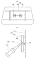
- FIG. 3 is a plan view of a pressurizing plate unit of FIG. 1 .
- FIG. 4 is a side view showing the coupling of a cylinder to the pressurizing plate unit of FIG. 3 .
- the windshield separation apparatus includes a support base 100 which is placed onto a seat of a scrapped vehicle 10, a pressurizing unit 200 which pressurizes a windshield 16, and a drive unit 300 which transmits drive force to the pressurizing unit 200.
- the drive unit 300 When the drive unit 300 is activated, the apparatus can automatically separate the windshield 16 from the scrapped from the vehicle 10.
- the pressurizing unit 200 is installed on the support base 100 of the windshield separation apparatus.
- the support base 100 is placed on the seat 14 when the windshield separation apparatus separates the windshield 16 from the vehicle.
- the support base 100 is placed on the floor of the scrapped vehicle 10 and supported by center pillars 12 when the windshield separation apparatus separates the windshield 16 from the vehicle.
- center pillars 12 refer to pillars that are disposed between first row seat doors and second row seat doors among pillars which connect a vehicle body to a vehicle roof panel.
- the pressurizing unit 200 functions to pressurize the windshield 16.
- a first end of the pressurizing unit 200 is connected to the support base 100, and a second end thereof is connected to the drive unit 300.
- the pressurizing unit 200 pressurizes the windshield 16 to separate it from the vehicle.
- the pressurizing unit 200 includes a cylinder 210 which is coupled at an end thereof to the support base 100.
- the cylinder 210 is operated by hydraulic or pneumatic pressure.
- the cylinder 210 is coupled to the support base 100 by a shaft so that the cylinder 210 can be rotated around the shaft in the clockwise or counterclockwise direction. Thereby, a position at which the cylinder 210 comes into contact with the windshield of the scrapped vehicle can be selected.
- the cylinder 210 includes a housing 211 which is coupled to the support base 100, and a cylinder rod 213 which is extracted from or retracted into the housing 211. To separate the windshield from the scrapped vehicle, an end of the cylinder rod 213 is brought into contact with the windshield before the drive unit 300 is operated.
- a windshield for vehicles is provided with a film such that, even if it is broken, pieces of glass are maintained in a state of being attached to the film, rather than being separated from each other, so as to protect a driver or a passenger. Therefore, if an area of the end of the cylinder rod 213 is increased merely to an appropriate extent so as to distribute the force of the cylinder rod 213 that is applied to the windshield, the windshield can be easily separated from the scrapped vehicle. However, there is the possibility that only a portion of the windshield to which the force is directly applied is removed from the scrapped vehicle.
- a pressurizing plate unit 400 be disposed between the cylinder rod 213 and the windshield 16 to pressurize the entirety or the perimeter of the windshield 16.
- the pressurizing plate unit 400 includes a pressurizing plate 410 and a plate support frame 410.
- the pressurizing plate 410 has a shape corresponding to that of the windshield 16 to be separated.
- the plate support frame 420 is installed on a rear surface of the pressurizing plate 410 to distribute the force of the cylinder rod 213 to the entire area of the pressurizing plate 410.
- the pressurizing plate 410 may be damaged.
- the plate support frame 420 is preferably provided on the pressurizing plate 410. The plate support frame 420 functions to distribute force applied from the cylinder rod 213 and increase the strength of the pressurizing plate 410.
- the plate support frame 420 is illustrated as including a pair of horizontal frames which are parallel to each other and a pair of vertical frames which are parallel to each other, the plate support frame 420 can have any structure, so long as it can increase the strength of the pressurizing plate 410 and distribute the force applied from the cylinder rod 213 to the pressurizing plate 410.
- the pressurizing plate 410 is temporarily fastened to the windshield of the scrapped vehicle, the support base 100 is placed on the first row seat of the scrapped vehicle, the end of the cylinder rod 213 is coupled to the pressurizing plate 410, and then the windshield is separated from the scrapped vehicle. During this process, a worker must temporarily fasten the pressurizing plate 410 to the windshield 16, before the cylinder rod 213 is coupled to the pressurizing plate 410.
- a suction plate 430 which can be attached to glass is preferably provided on the pressurizing plate 410.
- the pressurizing plate 410 is temporarily fastened to the windshield 16 by the suction plate 430, before the cylinder rod 213 is coupled to the pressurizing plate 410 to separate the windshield 16 from the scrapped vehicle.
- the pressurizing plate 410 that has been described above can be formed in a variety of shapes, because the windshield 16 for vehicles generally has an arc shape, which is convex towards the front of the vehicle, it is preferable that the pressurizing plate 410 has a shape corresponding to such a shape of the windshield 16.
- An insert depression 421 is preferably formed at a predetermined position in the plate support frame 420.
- the end of the cylinder rod 213 is inserted into the insert depression 421 and coupled to the plate support frame 420. If the insert depression 421 is not formed in the insert depression 421, the end of the cylinder rod 213 may be undesirably removed from the plate support frame 420 during the windshield separation operation. To prevent this, it is preferable that the insert depression 421 is formed in the plate support frame 420.
- a plurality of cylinders 210 are installed on different positions of the support base 100.
- the apparatus of the present invention may be configured such that when the pressure of any one of the cylinders is reduced, the drive unit 300 can increase the pressure of the other cylinder.
- the cylinders 210 are respectively coupled to the junctions between the vertical frames and the horizontal frames. Even though the same pressure is applied to the cylinders 210 at the initial stage of the windshield separation operation, a portion of the windshield which is adjacent to any one cylinder 210 may be separated from the vehicle before the other portions of the windshield which are adjacent to the other cylinders 210. In this case, the cylinder rod 213 of the cylinder 210 associated with the portion of the windshield that is separated from the vehicle is extended more easily than the cylinder rods 213 of the other cylinders 210. Thus, the pressure of the cylinder 210 associated with the separated portion of the windshield is reduced compared to that of the other cylinders 210.
- the windshield can be more effectively separated from the vehicle by increasing the pressures of the cylinders 210 other than the cylinder 210 associated with the separated portion of the windshield.
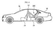
- the windshield separation apparatus according to the present invention has been illustrated as being applied to the front windshield 16 of the scrapped vehicle 10, it may be used to separate a rear windshield 18 from the scrapped vehicle 10, as shown in FIG. 6 that illustrates the operation of another embodiment of the apparatus of the present invention.
- the pressurizing plate 410 preferably has a shape corresponding to that of the rear windshield 18.
Landscapes
- Engineering & Computer Science (AREA)
- Life Sciences & Earth Sciences (AREA)
- Sustainable Development (AREA)
- Chemical & Material Sciences (AREA)
- Combustion & Propulsion (AREA)
- Transportation (AREA)
- Mechanical Engineering (AREA)
- Automobile Manufacture Line, Endless Track Vehicle, Trailer (AREA)
- Processing Of Solid Wastes (AREA)
Applications Claiming Priority (3)
| Application Number | Priority Date | Filing Date | Title |
|---|---|---|---|
| KR20120016630 | 2012-02-17 | ||
| PCT/KR2012/011636 WO2013122322A1 (ko) | 2012-02-17 | 2012-12-27 | 폐자동차 유리 분리장치 |
| KR20120155129A KR101434758B1 (ko) | 2012-02-17 | 2012-12-27 | 폐자동차 유리 분리장치 |
Publications (3)
| Publication Number | Publication Date |
|---|---|
| EP2826697A1 true EP2826697A1 (de) | 2015-01-21 |
| EP2826697A8 EP2826697A8 (de) | 2015-03-25 |
| EP2826697A4 EP2826697A4 (de) | 2015-10-21 |
Family
ID=49218664
Family Applications (1)
| Application Number | Title | Priority Date | Filing Date |
|---|---|---|---|
| EP12837605.0A Withdrawn EP2826697A4 (de) | 2012-02-17 | 2012-12-27 | Vorrichtung zur entnahme des glases aus einem entsorgten fahrzeug |
Country Status (4)
| Country | Link |
|---|---|
| EP (1) | EP2826697A4 (de) |
| JP (1) | JP5663676B2 (de) |
| KR (1) | KR101434758B1 (de) |
| WO (1) | WO2013122322A1 (de) |
Families Citing this family (3)
| Publication number | Priority date | Publication date | Assignee | Title |
|---|---|---|---|---|
| CN104210573B (zh) * | 2014-09-22 | 2016-09-14 | 常熟理工学院 | 报废汽车的挡风玻璃无损拆解装置 |
| CN105736537A (zh) * | 2016-01-25 | 2016-07-06 | 福耀集团长春有限公司 | 用于汽车玻璃生产线的玻璃托架安装工装 |
| CN107297612B (zh) * | 2017-02-17 | 2023-06-16 | 福耀集团(沈阳)汽车玻璃有限公司 | 一种侧边玻璃金属托架安装工装 |
Family Cites Families (7)
| Publication number | Priority date | Publication date | Assignee | Title |
|---|---|---|---|---|
| SE8500565L (sv) * | 1985-02-07 | 1986-08-08 | Kenth Wettersten | Monteringsverktyg |
| US5953802A (en) * | 1998-02-17 | 1999-09-21 | Radzio; Matthew D. | Windshield removal jack |
| US6101702A (en) * | 1998-02-19 | 2000-08-15 | Claycomb; Kevin | Windshield lift and method of use |
| KR100305348B1 (ko) * | 1999-06-03 | 2001-09-24 | 이계안 | 폐자동차 윈드실드/리어 글라스 해체 장치 |
| KR100384012B1 (ko) * | 2000-08-10 | 2003-05-14 | 현대자동차주식회사 | 폐자동차용 프론트 및 리어 도어 글래스의 동시 파쇄 장치 |
| JP2004148919A (ja) * | 2002-10-29 | 2004-05-27 | Asahi Glass Co Ltd | 自動車の窓ガラス取外し方法 |
| JP2005206020A (ja) * | 2004-01-22 | 2005-08-04 | Asahi Glass Co Ltd | 窓用合わせガラスの回収方法及び回収治具 |
-
2012
- 2012-12-27 KR KR20120155129A patent/KR101434758B1/ko not_active Expired - Fee Related
- 2012-12-27 JP JP2013558803A patent/JP5663676B2/ja not_active Expired - Fee Related
- 2012-12-27 EP EP12837605.0A patent/EP2826697A4/de not_active Withdrawn
- 2012-12-27 WO PCT/KR2012/011636 patent/WO2013122322A1/ko not_active Ceased
Also Published As
| Publication number | Publication date |
|---|---|
| WO2013122322A1 (ko) | 2013-08-22 |
| EP2826697A8 (de) | 2015-03-25 |
| JP5663676B2 (ja) | 2015-02-04 |
| KR101434758B1 (ko) | 2014-08-29 |
| EP2826697A4 (de) | 2015-10-21 |
| JP2014508073A (ja) | 2014-04-03 |
| KR20130095169A (ko) | 2013-08-27 |
Similar Documents
| Publication | Publication Date | Title |
|---|---|---|
| TWI444238B (zh) | 廢料剪斷機 | |
| GB2522368B (en) | Assembly method for vehicle body and assembly device for same | |
| US20040231398A1 (en) | Modular die press assembly | |
| JP2004322998A (ja) | 廃自動車のドアガラスサンカットフィルムの自動剥離装置 | |
| CN104525741A (zh) | 一种汽车纵梁后部封板零件的连续生产模具 | |
| JP5663676B2 (ja) | 廃自動車ガラスの分離装置 | |
| US20120012735A1 (en) | Sidewall unit for casting mold and removal unit for sidewall unit | |
| CN102202841A (zh) | 废旧轮胎回收设备 | |
| KR101239062B1 (ko) | 자동차용 브레이크패드의 이물질 제거장치 | |
| DE102004060142B3 (de) | Verfahren und Vorrichtung zur Demontage von Bildschirmgeräten | |
| EP2415576A1 (de) | Verfahren zum Aufnehmen eines Gussstücks | |
| JPH0664503A (ja) | 自動車の解体方法 | |
| JP2742365B2 (ja) | 自動車の解体方法 | |
| KR101330002B1 (ko) | 폐자동차의 대시보드 분리장치 | |
| CN217942525U (zh) | 一种便于移动的液压闸式横切机 | |
| CA2633034A1 (en) | Blank support device | |
| KR101064107B1 (ko) | 이동식 고철 처리장치 | |
| KR102678398B1 (ko) | 타이어 분리 장치 | |
| JP2000094239A (ja) | 自動車の解体方法 | |
| JP2001225128A (ja) | ワーク搬入出装置 | |
| JP2021074752A (ja) | 鍛造装置 | |
| CN201046694Y (zh) | 汽车安全气囊折袋装置 | |
| KR101625732B1 (ko) | 타이어 비드 와이어 분리 장치 | |
| CN112024640A (zh) | 一种钢材矫正设备 | |
| CN214866533U (zh) | 一种压力机防跳脱装置 |
Legal Events
| Date | Code | Title | Description |
|---|---|---|---|
| PUAI | Public reference made under article 153(3) epc to a published international application that has entered the european phase |
Free format text: ORIGINAL CODE: 0009012 |
|
| 17P | Request for examination filed |
Effective date: 20130405 |
|
| AK | Designated contracting states |
Kind code of ref document: A1 Designated state(s): AL AT BE BG CH CY CZ DE DK EE ES FI FR GB GR HR HU IE IS IT LI LT LU LV MC MK MT NL NO PL PT RO RS SE SI SK SM TR |
|
| AX | Request for extension of the european patent |
Extension state: BA ME |
|
| DAX | Request for extension of the european patent (deleted) | ||
| RA4 | Supplementary search report drawn up and despatched (corrected) |
Effective date: 20150918 |
|
| RIC1 | Information provided on ipc code assigned before grant |
Ipc: B62D 67/00 20060101AFI20150914BHEP Ipc: B25B 27/00 20060101ALI20150914BHEP |
|
| STAA | Information on the status of an ep patent application or granted ep patent |
Free format text: STATUS: THE APPLICATION IS DEEMED TO BE WITHDRAWN |
|
| 18D | Application deemed to be withdrawn |
Effective date: 20160419 |