EP2828068B1 - Substrat destiné à la fabrication additive - Google Patents
Substrat destiné à la fabrication additive Download PDFInfo
- Publication number
- EP2828068B1 EP2828068B1 EP13711944.2A EP13711944A EP2828068B1 EP 2828068 B1 EP2828068 B1 EP 2828068B1 EP 13711944 A EP13711944 A EP 13711944A EP 2828068 B1 EP2828068 B1 EP 2828068B1
- Authority
- EP
- European Patent Office
- Prior art keywords
- substrate
- build surface
- protrusions
- powder bed
- bed system
- Prior art date
- Legal status (The legal status is an assumption and is not a legal conclusion. Google has not performed a legal analysis and makes no representation as to the accuracy of the status listed.)
- Active
Links
Images


Classifications
-
- B—PERFORMING OPERATIONS; TRANSPORTING
- B29—WORKING OF PLASTICS; WORKING OF SUBSTANCES IN A PLASTIC STATE IN GENERAL
- B29C—SHAPING OR JOINING OF PLASTICS; SHAPING OF MATERIAL IN A PLASTIC STATE, NOT OTHERWISE PROVIDED FOR; AFTER-TREATMENT OF THE SHAPED PRODUCTS, e.g. REPAIRING
- B29C64/00—Additive manufacturing, i.e. manufacturing of three-dimensional [3D] objects by additive deposition, additive agglomeration or additive layering, e.g. by 3D printing, stereolithography or selective laser sintering
- B29C64/10—Processes of additive manufacturing
- B29C64/141—Processes of additive manufacturing using only solid materials
- B29C64/153—Processes of additive manufacturing using only solid materials using layers of powder being selectively joined, e.g. by selective laser sintering or melting
-
- B—PERFORMING OPERATIONS; TRANSPORTING
- B22—CASTING; POWDER METALLURGY
- B22F—WORKING METALLIC POWDER; MANUFACTURE OF ARTICLES FROM METALLIC POWDER; MAKING METALLIC POWDER; APPARATUS OR DEVICES SPECIALLY ADAPTED FOR METALLIC POWDER
- B22F10/00—Additive manufacturing of workpieces or articles from metallic powder
-
- B—PERFORMING OPERATIONS; TRANSPORTING
- B22—CASTING; POWDER METALLURGY
- B22F—WORKING METALLIC POWDER; MANUFACTURE OF ARTICLES FROM METALLIC POWDER; MAKING METALLIC POWDER; APPARATUS OR DEVICES SPECIALLY ADAPTED FOR METALLIC POWDER
- B22F10/00—Additive manufacturing of workpieces or articles from metallic powder
- B22F10/20—Direct sintering or melting
- B22F10/28—Powder bed fusion, e.g. selective laser melting [SLM] or electron beam melting [EBM]
-
- B—PERFORMING OPERATIONS; TRANSPORTING
- B22—CASTING; POWDER METALLURGY
- B22F—WORKING METALLIC POWDER; MANUFACTURE OF ARTICLES FROM METALLIC POWDER; MAKING METALLIC POWDER; APPARATUS OR DEVICES SPECIALLY ADAPTED FOR METALLIC POWDER
- B22F12/00—Apparatus or devices specially adapted for additive manufacturing; Auxiliary means for additive manufacturing; Combinations of additive manufacturing apparatus or devices with other processing apparatus or devices
- B22F12/30—Platforms or substrates
-
- B—PERFORMING OPERATIONS; TRANSPORTING
- B29—WORKING OF PLASTICS; WORKING OF SUBSTANCES IN A PLASTIC STATE IN GENERAL
- B29C—SHAPING OR JOINING OF PLASTICS; SHAPING OF MATERIAL IN A PLASTIC STATE, NOT OTHERWISE PROVIDED FOR; AFTER-TREATMENT OF THE SHAPED PRODUCTS, e.g. REPAIRING
- B29C64/00—Additive manufacturing, i.e. manufacturing of three-dimensional [3D] objects by additive deposition, additive agglomeration or additive layering, e.g. by 3D printing, stereolithography or selective laser sintering
- B29C64/20—Apparatus for additive manufacturing; Details thereof or accessories therefor
- B29C64/245—Platforms or substrates
-
- B—PERFORMING OPERATIONS; TRANSPORTING
- B29—WORKING OF PLASTICS; WORKING OF SUBSTANCES IN A PLASTIC STATE IN GENERAL
- B29C—SHAPING OR JOINING OF PLASTICS; SHAPING OF MATERIAL IN A PLASTIC STATE, NOT OTHERWISE PROVIDED FOR; AFTER-TREATMENT OF THE SHAPED PRODUCTS, e.g. REPAIRING
- B29C64/00—Additive manufacturing, i.e. manufacturing of three-dimensional [3D] objects by additive deposition, additive agglomeration or additive layering, e.g. by 3D printing, stereolithography or selective laser sintering
- B29C64/40—Structures for supporting 3D objects during manufacture and intended to be sacrificed after completion thereof
-
- B—PERFORMING OPERATIONS; TRANSPORTING
- B33—ADDITIVE MANUFACTURING TECHNOLOGY
- B33Y—ADDITIVE MANUFACTURING, i.e. MANUFACTURING OF THREE-DIMENSIONAL [3D] OBJECTS BY ADDITIVE DEPOSITION, ADDITIVE AGGLOMERATION OR ADDITIVE LAYERING, e.g. BY 3D PRINTING, STEREOLITHOGRAPHY OR SELECTIVE LASER SINTERING
- B33Y30/00—Apparatus for additive manufacturing; Details thereof or accessories therefor
-
- B—PERFORMING OPERATIONS; TRANSPORTING
- B33—ADDITIVE MANUFACTURING TECHNOLOGY
- B33Y—ADDITIVE MANUFACTURING, i.e. MANUFACTURING OF THREE-DIMENSIONAL [3D] OBJECTS BY ADDITIVE DEPOSITION, ADDITIVE AGGLOMERATION OR ADDITIVE LAYERING, e.g. BY 3D PRINTING, STEREOLITHOGRAPHY OR SELECTIVE LASER SINTERING
- B33Y40/00—Auxiliary operations or equipment, e.g. for material handling
-
- B—PERFORMING OPERATIONS; TRANSPORTING
- B22—CASTING; POWDER METALLURGY
- B22F—WORKING METALLIC POWDER; MANUFACTURE OF ARTICLES FROM METALLIC POWDER; MAKING METALLIC POWDER; APPARATUS OR DEVICES SPECIALLY ADAPTED FOR METALLIC POWDER
- B22F10/00—Additive manufacturing of workpieces or articles from metallic powder
- B22F10/70—Recycling
- B22F10/73—Recycling of powder
-
- B—PERFORMING OPERATIONS; TRANSPORTING
- B29—WORKING OF PLASTICS; WORKING OF SUBSTANCES IN A PLASTIC STATE IN GENERAL
- B29K—INDEXING SCHEME ASSOCIATED WITH SUBCLASSES B29B, B29C OR B29D, RELATING TO MOULDING MATERIALS OR TO MATERIALS FOR MOULDS, REINFORCEMENTS, FILLERS OR PREFORMED PARTS, e.g. INSERTS
- B29K2995/00—Properties of moulding materials, reinforcements, fillers, preformed parts or moulds
- B29K2995/0037—Other properties
- B29K2995/0082—Flexural strength; Flexion stiffness
-
- B—PERFORMING OPERATIONS; TRANSPORTING
- B29—WORKING OF PLASTICS; WORKING OF SUBSTANCES IN A PLASTIC STATE IN GENERAL
- B29L—INDEXING SCHEME ASSOCIATED WITH SUBCLASS B29C, RELATING TO PARTICULAR ARTICLES
- B29L2031/00—Other particular articles
- B29L2031/757—Moulds, cores, dies
-
- Y—GENERAL TAGGING OF NEW TECHNOLOGICAL DEVELOPMENTS; GENERAL TAGGING OF CROSS-SECTIONAL TECHNOLOGIES SPANNING OVER SEVERAL SECTIONS OF THE IPC; TECHNICAL SUBJECTS COVERED BY FORMER USPC CROSS-REFERENCE ART COLLECTIONS [XRACs] AND DIGESTS
- Y02—TECHNOLOGIES OR APPLICATIONS FOR MITIGATION OR ADAPTATION AGAINST CLIMATE CHANGE
- Y02P—CLIMATE CHANGE MITIGATION TECHNOLOGIES IN THE PRODUCTION OR PROCESSING OF GOODS
- Y02P10/00—Technologies related to metal processing
- Y02P10/25—Process efficiency
Definitions
- the present invention relates to a powder bed system for creating a part by a powder-based additive manufacturing process, the powder bed system comprising a substrate, and to the use of the system for creating a part by an additive manufacturing process.
- Additive manufacturing is a process by which an article is produced by joining materials together.
- Additive layer manufacturing involves producing the article layer by layer using 3D model data. The process may be used for producing prototypes, samples, models, tooling or full scale components.
- a known ALM technique uses a power beam, such as a laser or an electron beam for example, to selectively sinter powdered material.
- a layer of the powdered material is laid over a substrate (also known as a build plate, start plate, start platform or build platform) in a sintering chamber to provide a "powder bed".
- the powder is applied using a re-coating blade.
- the power beam is used to selectively sinter the powder in a desired pattern by scanning across the surface of the powder bed.
- the power beam is controlled to produce the desired pattern according to cross-sections generated from 3D model data (e.g. a CAD file) of the article.
- 3D model data e.g. a CAD file
- the substrate is lowered by one layer thickness (typically of the order of 0.1 mm) to prepare for growth of the next layer.
- Another layer of the powder is applied on top of the preceding layer in preparation for sintering. The process is repeated until the article is completed.
- a sintered article is constructed, supported by unconsolidated powder. After the article has been completed it is removed from the substrate and the unconsolidated powder is typically recycled to produce another article by the same ALM process.
- Selective sintering may be used to produce shaped articles from powders of some metals, ceramics, glasses and thermoplastic polymers.
- the article is generally constrained by fusing it to the substrate.
- a thick, solid substrate is used and the first layer of powder is fused to this, with subsequent layers being built on top.
- the fusion to the substrate provides the desired constraint in the z-axis (through layers) but also applies an additional constraint in the x-y plane, resulting in high residual stresses in the article which cannot be relieved during the build process. This can lead to bending of the substrate, and distortion and cracking of the article.
- ALM processes that make use of either a heated sintering chamber, or a heated substrate in order to reduce the level of differential shrinkage between the article and the substrate. This can reduce the level of residual stress, but has other drawbacks.
- the heated nature of the process results in a significant increase in system complexity, requiring heat shielding of sensitive electronics. It also changes the environment of the process, changing cooling characteristics which can be advantageous for some alloys, but can have a severe detrimental effect on other, e.g. Scalmalloy TM, which requires fast solidification and high cooling rates.
- EP1279480 describes an apparatus for creating three-dimensional objects and includes a build base plate having grooves therein.
- WO2005/025781 describes a substrate sheet for a 3D-shaping method, wherein a mounting section includes recesses.
- WO2010/049696 describes an additive manufacturing apparatus and method in which a removable metallic base-layer is used.
- GB2458745 describes a method of forming a support for use in a selective sintering process in which the support has a plurality of parallel grooves.
- WO201044008 describes a method of manufacturing a grid for selective transmission of electromagnetic radiation.
- a first aspect of the invention provides a powder bed system as defined in claim 1.
- the aspect ratio is the ratio of the height of the protrusion vs. its width/depth.
- the aspect ratio may be in the range 3 to 10, preferably 4 to 8, and most preferable 5 to 6.
- a further aspect of the invention provides use of a system according to the invention for creating a part by an additive manufacturing process.
- the invention is advantageous in that the substrate allows high strain deformation in the plane of the build surface, but retains high stiffness in the direction of the build, i.e. perpendicular to the build surface. This effectively creates a sliding constraint at the interface between the substrate and the part being formed by the additive manufacturing process, allowing the part to shrink in the plane of the build surface and thereby avoiding the build up of large residual stresses.
- Preferred embodiments of the invention provide various ways in which this can be achieved.
- the protrusions may be arranged to deform like beams in the plane of the build surface, whilst being substantially rigid in the direction perpendicular to the build surface.
- the tops of the protrusions may provide at least a portion of the build surface.
- the entire upper portion of the substrate may comprise the protrusions, in which case the tops of the protrusions may provide the entire build surface.
- the protrusions may be provided on only a portion of the build surface.
- the remainder of the build surface may be solid. It may be advantageous to provide the protrusions only at those regions of the build surface upon which the part is to be built.
- each protrusion, or an array of protrusions may be attached to the lower portion of the substrate, e.g. by fastening. This may allow for use of a common lower portion with one of a plurality of different upper portions than can be exchanged.
- the protrusions may each have straight sides substantially perpendicular to the build surface.
- the protrusions may each have a taper of increasing cross section along their longitudinal axis.
- the protrusions may have a taper of increasing cross section towards the build surface, i.e. an inverse taper. In this way the base of the protrusions provide great flexibility, whilst the top of the protrusions have only a small gap to their neighbouring protrusions in the array.
- the protrusions take the form of pillars having a generally planar top.
- the pillars may have any cross section, but are preferably regularly shaped such that the gap between neighbouring pillars is substantially constant.
- the pillars may have a rectangular section, constant along the length of the protrusion.
- a hexagonal, octagonal, circular, elliptical or other section may be provided.
- a gap between adjacent protrusions may be filled by a material dissimilar to that of the protrusions.
- the gap may be filled with a material of low stiffness as compared with that of the protrusions.
- the gap may be an air gap, i.e. a material of negligible stiffness.
- the protrusions may be formed by cutting slits in the substrate.
- the slits may be provided in an upper portion of the substrate, and a lower portion of the substrate may be substantially solid.
- the slits may take the form of a grid.
- the build surface may be substantially rectangular and the grid may be aligned substantially with an edge or a diagonal of the build surface. Aligning with the diagonal may be preferable, such that the part being built by the additive manufacturing process may be arranged diagonally on the build surface. In this way larger parts can be built for a given size of substrate or ALM system.
- the slits may be provided on only a portion of the build surface.
- the slits may have a substantially uniform width.
- the slits may have a particularly small width, e.g. approximately 0.1 mm, and a high aspect ratio.
- the aspect ratio is the length of the slit in the direction extending from the build surface vs. the slit width.
- the aspect ratio may therefore be at least 100, preferably at least 150, and may be up to approximately 500.
- Cutting the slits with such a high aspect ratio can be achieved using electrical discharge machining (EDM), e.g. wire EDM. Alternatively laser cutting may be used, for example.
- EDM electrical discharge machining
- wire EDM e.g. wire EDM.
- laser cutting may be used, for example.
- each slit may have a radius corner so as to protect against stress concentrations and crack propagation into the substrate from the end of the slit.
- the radius may be generally U-shaped or generally tear drop shaped.
- the radius may be at least 0.5 times the width of the slit, preferably at least 2 times.
- the substrate may be re-useable for building successive part(s) by the additive manufacturing process.
- a top layer of the substrate may be adapted to be removed after each build to redefine the build surface.
- the thickness and/or construction of the upper portion of the substrate may be arranged to permit at least 5, and preferably at least 10, builds.
- a thickness of approximately 1 mm may be milled, or otherwise removed, from the top of the substrate to redefine the build surface after each build. Removing this material from the substrate is intended to remove any material that may have plastically deformed during the previous build, leaving only material that has elastically deformed remaining in the substrate.
- the material properties, and/or the construction (e.g. slit gap width) in the build surface may therefore be restored.
- the additive manufacturing process typically progresses by creating the part layer by layer.
- the part may be created by selectively sintering successive powder layers.
- the substrate may alternatively be used with other additive manufacturing processes.
- FIG 1 illustrates a cold powder bed processing additive layer manufacturing (ALM) system.
- the system is "cold” in that the processing environment is at ambient temperature, and is not maintained at an elevated temperature.
- the system comprises a pair of feed containers 10, 11 containing powdered metallic material such as powdered Titanium.
- a roller 12 picks up powder from one of the feed containers (in the example of Figure 1 , the roller 12 is picking up powder from the right hand feed container) and rolls a continuous bed of powder over a substrate 13.
- a laser head 14 then scans over the powder bed, and a laser beam from the head is turned on and off to melt the powder in a desired pattern.
- the substrate 13 then moves down by a small distance (typically of the order of 0.1 mm) to prepare for growth of the next layer. After a pause for the melted powder to solidify, the roller 12 proceeds to roll another layer of powder over substrate 13 in preparation for sintering. Thus as the process proceeds, a sintered part 15 is constructed, supported by unconsolidated powder parts 16. After the part has been completed, it is removed from substrate 13 and the unconsolidated powder 16 is recycled before being returned to the feed containers 10, 11.
- a small distance typically of the order of 0.1 mm
- Movement of the laser head 14 and modulation of the laser beam is determined by a Computer Aided Design (CAD) model of the desired profile and layout of the part.
- CAD Computer Aided Design
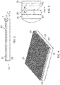
- Figures 2 to 4 illustrate a first embodiment of the substrate 13'.
- the substrate 13' has a build surface 20.
- the first layer of powder laid on the build surface 20 is fused to the build surface across substantially the entire base area of the part to be formed by the ALM process. This fixes the part to the substrate and substantially prevents curling of the part during the build.
- the substrate 13' is configured to provide relatively high stiffness in a direction (z) substantially perpendicular to the build surface, whilst having a low longitudinal stiffness in the plane (x-y) of the build surface.
- the substrate 13' has an upper portion 21 nearest the build surface 20 and a lower portion 22.
- the material for the upper and lower portions 21, 22 is the same, and in this example is Titanium to provide a suitable match with the Ti 6-4 powder used to create the part 15. This material match is important for fusing the part to the substrate.
- the upper portion 21 of the substrate includes an array of slits 23 extending from the build surface 20 through part of the thickness of the substrate.
- the slits 23 form a rectangular grid pattern across the build surface 20 to define an array of protrusions 24 with their longitudinal axis aligned with the build direction (z) and substantially perpendicular to the build surface 20.
- the slits 23 have a width s of approximately 0.1 mm and a depth d of approximately 15 mm.
- the slits are regularly spaced approximately 3 mm apart such that the protrusions 24 are square section pillars, having a height of approximately 15 mm and a 3 x 3 mm cross section with parallel sides aligned with the z direction.
- the tops 25 of the pillars make up the build surface 20.
- the slits 23 are cut by spark erosion, such as wire EDM, or may alternatively be laser cut.
- the substrate 13' may initially be similar to a conventional Titanium plate substrate for powder bed ALM. Cutting the slits 23 into the monolithic plate has the effect of maintaining high stiffness in the z direction whilst introducing relatively low longitudinal stiffness in the x-y plane of the build plate. Due to the slits 23 the resultant base of the pillars remain integrally formed with the lower portion 22 of the substrate, and the pillars act as beams for deflection in the x-y plane at the build surface 20.
- the material shrinkage which occurs as the sintered powder solidifies during creation of each successive layer of the ALM part 15 is accommodated by bending of the pillars about their respective bases.
- This has the effect of closing up at least some of the slits 23, with this effect being most pronounced at the edges of the part 15.
- this slightly disturbs the planar build surface such that small steps are created between adjacent pillars but this step is small due to the size (3 x 3 mm) of the top of the pillars and the very high aspect ratio of the slits, which in this example is 150.
- the higher the aspect ratio of the slits the flatter the build surface will be at maximum deflection of the pillars.
- the base of the slits 23 has a radius r of approximately 0.05 mm so as to function as crack inhibitors and prevent crack propagation through the substrate.
- the substrate 13' includes mounting holes 26, one at each corner of the substrate for fixing, e.g. by bolting, the substrate to the ALM system transport for raising/lowering the substrate.
- the lower portion 22 of the substrate 13' is substantially isotropic, whilst the upper portion 21 having the slits 23 is anisotropic.
- the lower portion 22 is sufficiently stiff to prevent bending or curling of the substrate 13' during the build.
- the upper portion 21 maintains sufficient stiffness in the z-direction, whilst having a low longitudinal stiffness in the x-y plane of the build surface 20.
- the deformation in the upper portion 21 due to bending of the pillars is mostly elastic but the design accommodates a limited degree of plastic deformation, if particularly high residual stresses are created, e.g. due to the shape of the part being built.
- the top 1 mm or so of the substrate 13' can be milled away after each build so as to redefine the build surface. This beneficially removes any material that may have plastically deformed during the last build.
- the substrate 13' is thus re-useable a plurality of times. With sufficient depth of the slits 23 the substrate 13' may be re-used up to approximately 5 to 10 times.
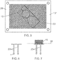
- Figure 5 illustrates an alternative embodiment of the substrate 13", which differs in that the slit grid occupies only a portion of the build surface 20 and in that the slit grid is oriented approximately along the diagonal of the rectangular build surface.
- Figure 6 illustrates a schematic detailed view of the base of the slits 23' in accordance with another embodiment, in which the radiused base has a tear drop shape so as to maximise the radius r, thus further improving resistance to crack propagation through the substrate.
- a gap between adjacent pillars defined by the slits 23 is typically air filled, but in an alternative embodiment this gap may be filled with a material different than that of the pillars, e.g. a ductile plastics material. Filling the slits may prevent the powder from falling into the slits. However, even with an air gap this is generally not problematic.
- the very narrow slit width s of approximately 0.01 mm is approximately twice the diameter of the powder particles used in the ALM process. This is beneficial as the powder particles will tend to easily bridge the slits in the build surface during application of the first or second powder layers.
- Figure 7 illustrates this bridging effect, and also shows a cut line 30 for cutting the completed part 15 from the substrate 13 by wire EDM, or similar.
- this cut line 30 is disposed just above the bridging between adjacent pillars. This leaves a small thickness of the sintered powder material fused to the substrate, which is removed when the top layer of the substrate is milled after the build to redefine the build surface in readiness for a subsequent build.
- FIG 8 illustrates schematically a yet further design of the protrusions and slits in the upper portion of the substrate.
- the protrusions 24" have a tapered shape, as compared with this straight sided protrusions described previously.
- the protrusions 24" retain a substantially rectangular cross section but have a taper of increasing cross section towards the build surface 20.
- the slits 23" have a corresponding taper of increasing cross section away from the build surface 20.
- the tapered protrusions are advantageous in that the base has a reduced cross section, which promotes greater bending of the beam like protrusions in the x-y plane at the build surface 20.
- the slits 23" however may be more difficult to manufacture. Accordingly, it may be preferable to manufacture the substrate having the protrusions in the upper portion by an ALM process, such as that described above. Forming re-entrant or undercut projections is generally straightforward in ALM.
- Figure 9 illustrates a yet further embodiment of the substrate 13'" having an upper portion 41 of a first material and a lower portion 42 of a second material.
- both the upper and lower portions are solid, and the upper portion in particular is free from slits.
- the lower portion has a higher stiffness than the upper portion.
- the upper portion 41 includes a material of high ductility and low yield strength such as grade 1 or grade 2 pure Titanium. This provides a good match for the Titanium 6-4 material used to form the part as the part will readily fuse to the substrate.
- the upper portion 41 may include a material of low elastic modulus and high strain to failure as compared with the material of the part intended to be fused to it during the additive manufacturing process.
- a super-elastic material such as the shape memory alloy Nitinol may be used, which includes approximately 50% Ni and 50% Ti.
- the upper portion 41 includes a material that is weldable with the material of the part intended to be fused to it during the additive manufacturing process. The large proportion of Titanium in Nitinol would satisfy this requirement when building parts from Titanium powder by ALM.
- the overall depth of the substrate may increase slightly as compared with the embodiments described with reference to Figures 2 to 4 .
- the part is typically heat treated to reduce any remaining residual stresses. So long as the modified substrate in accordance with this invention can prevent crack initiation during the build, due to the increased strain deformation across the build surface, then the finished part should be free from stress induced defects.
Landscapes
- Engineering & Computer Science (AREA)
- Chemical & Material Sciences (AREA)
- Materials Engineering (AREA)
- Manufacturing & Machinery (AREA)
- Physics & Mathematics (AREA)
- Optics & Photonics (AREA)
- Mechanical Engineering (AREA)
- Plasma & Fusion (AREA)
- Powder Metallurgy (AREA)
Claims (13)
- Système de lit de poudre destiné à générer une pièce par un procédé de fabrication additive à base de poudre, le système de lit de poudre comprenant un substrat (13) ayant une surface de construction (20) pour la fusion en une pièce à former sur le substrat par le procédé de fabrication additive, le substrat ayant une partie supérieure (21) la plus proche de la surface de construction et un partie inférieure (22), caractérisé en ce que la partie supérieure inclut un réseau de protubérances (24) avec leurs axes longitudinaux alignés sensiblement perpendiculairement à la surface de construction, les protubérances étant fines et ayant un rapport de forme d'au moins 3, et les protubérances prenant la forme de piliers ayant une partie supérieure généralement plane.
- Système de lit de poudre suivant la revendication 1, dans lequel les parties supérieures (25) des protubérances fournissent au moins une partie de la surface de construction.
- Système de lit de poudre suivant la revendication 1 ou 2, dans lequel les protubérances présentent chacune des côtés droits sensiblement perpendiculaires à la surface de construction.
- Système de lit de poudre suivant la revendication 1 ou 2, dans lequel les protubérances présentent chacune une inclinaison d'une section transversale croissante envers la surface de construction.
- Système de lit de poudre suivant une des revendications 1 à 4, dans lequel le substrat est un monolithe.
- Système de lit de poudre suivant une des revendications 1 à 4, dans lequel un écart entre des protubérances adjacentes est rempli par un matériau dissemblable de celui des protubérances.
- Système de lit de poudre suivant une des revendications 1 à 6, dans lequel le réseau de protubérances est formé par des fentes (23) s'étendant de la surface de construction à travers une partie de l'épaisseur du substrat.
- Système de lit de poudre suivant la revendication 7, dans lequel les fentes sont prévues dans la partie supérieure du substrat et la partie inférieure du substrat est sensiblement solide.
- Système de lit de poudre suivant la revendication 7 ou 8, dans lequel les fentes forment une grille.
- Système de lit de poudre suivant la revendication 9, dans lequel la surface de construction est sensiblement rectangulaire et la grille est sensiblement alignée avec un angle ou une diagonale de la surface de construction.
- Système de lit de poudre suivant une des revendications 7 à 10, dans lequel la base de chaque fente présente un rayon de courbure.
- Utilisation d'un système suivant une des revendications 1 à 11 destiné à générer une pièce par un procédé de fabrication additive.
- Utilisation d'un système suivant la revendication 12, dans lequel une couche supérieure du substrat est enlevée après chaque construction pour redéfinir la surface de construction.
Applications Claiming Priority (2)
| Application Number | Priority Date | Filing Date | Title |
|---|---|---|---|
| GB1204922.7A GB2500412A (en) | 2012-03-21 | 2012-03-21 | Build Plate for an additive manufacturing process |
| PCT/GB2013/050686 WO2013140146A1 (fr) | 2012-03-21 | 2013-03-18 | Substrat destiné à la fabrication additive |
Publications (2)
| Publication Number | Publication Date |
|---|---|
| EP2828068A1 EP2828068A1 (fr) | 2015-01-28 |
| EP2828068B1 true EP2828068B1 (fr) | 2021-04-21 |
Family
ID=46052268
Family Applications (1)
| Application Number | Title | Priority Date | Filing Date |
|---|---|---|---|
| EP13711944.2A Active EP2828068B1 (fr) | 2012-03-21 | 2013-03-18 | Substrat destiné à la fabrication additive |
Country Status (5)
| Country | Link |
|---|---|
| US (1) | US10046524B2 (fr) |
| EP (1) | EP2828068B1 (fr) |
| JP (1) | JP2015516316A (fr) |
| GB (1) | GB2500412A (fr) |
| WO (1) | WO2013140146A1 (fr) |
Families Citing this family (27)
| Publication number | Priority date | Publication date | Assignee | Title |
|---|---|---|---|---|
| DE102014207510B4 (de) | 2014-04-17 | 2021-12-16 | Kennametal Inc. | Zerspanungswerkzeug sowie Verfahren zum Herstellen eines Zerspanungswerkzeugs |
| DE102014207507B4 (de) | 2014-04-17 | 2021-12-16 | Kennametal Inc. | Zerspanungswerkzeug sowie Verfahren zum Herstellen eines Zerspanungswerkzeugs |
| JP2016053198A (ja) * | 2014-09-04 | 2016-04-14 | 株式会社コイワイ | 金属成形体および金属成形体用金属粉末 |
| GB2531704A (en) * | 2014-10-17 | 2016-05-04 | Airbusgroup Ltd | Method of additive maufacturing and heat treatment |
| US9908287B2 (en) | 2014-11-20 | 2018-03-06 | Ut-Battelle, Llc | Build platform that provides mechanical engagement with additive manufacturing prints |
| JP6843047B2 (ja) | 2014-12-05 | 2021-03-17 | ユニバーシティ オブ フロリダ リサーチ ファンデーション インコーポレーティッド | 支持体として相変化物質を用いた3d印刷 |
| US10927987B2 (en) * | 2015-09-22 | 2021-02-23 | Raytheon Company | Duct with shape memory material, and installation method |
| JP6643631B2 (ja) | 2016-03-09 | 2020-02-12 | パナソニックIpマネジメント株式会社 | 三次元形状造形物の製造方法 |
| DE102016105215A1 (de) | 2016-03-21 | 2017-09-21 | GEFERTEC GmbH | Bauplattformsystem und Verfahren zur additiven Fertigung eines Formkörpers |
| JP6220459B1 (ja) * | 2016-03-25 | 2017-10-25 | 技術研究組合次世代3D積層造形技術総合開発機構 | 3次元積層造形装置、3次元積層造形装置の制御方法および3次元積層造形装置の制御プログラム |
| US11124644B2 (en) | 2016-09-01 | 2021-09-21 | University Of Florida Research Foundation, Inc. | Organic microgel system for 3D printing of silicone structures |
| JP6860841B2 (ja) * | 2016-10-28 | 2021-04-21 | 株式会社リコー | 三次元造形装置、載置部材及び三次元造形物の製造方法 |
| US11660819B2 (en) | 2016-11-02 | 2023-05-30 | R3 Printing, Inc. | System and method for automated successive three-dimensional printing |
| US10723075B2 (en) | 2016-11-02 | 2020-07-28 | R3 Printing, Inc. | System and method for automated successive three-dimensional printing |
| DE102016222555A1 (de) * | 2016-11-16 | 2018-05-17 | Siemens Aktiengesellschaft | Verfahren zur additiven Herstellung eines Bauteils und computerlesbares Medium |
| US11084096B2 (en) * | 2017-08-17 | 2021-08-10 | General Electric Company | Movable wall for additive powder bed |
| US10538035B2 (en) * | 2017-12-09 | 2020-01-21 | Arevo, Inc. | Consumable scaffold for 3D printing of high-tensile-strength materials |
| EP3593997A3 (fr) * | 2018-02-28 | 2020-04-08 | Ricoh Company, Ltd. | Procédé de production d'objet tridimensionnel, appareil de production d'objet tridimensionnel et objet tridimensionnel |
| FR3081375B1 (fr) * | 2018-05-25 | 2021-12-24 | Addup | Methode de preparation de la surface superieure d'un plateau de fabrication additive par depot de lit de poudre |
| US11426818B2 (en) | 2018-08-10 | 2022-08-30 | The Research Foundation for the State University | Additive manufacturing processes and additively manufactured products |
| CN109079138B (zh) * | 2018-09-30 | 2024-04-26 | 航天科工(长沙)新材料研究院有限公司 | 一种增材制造重复使用基板及重复使用方法 |
| GB2582567A (en) * | 2019-03-25 | 2020-09-30 | Airbus Operations Ltd | Fixture for additive manufacturing and heat treatment |
| US12220863B2 (en) * | 2019-04-11 | 2025-02-11 | Smith & Nephew, Inc. | Medical devices and methods for forming medical devices containing a build plate |
| JP7447465B2 (ja) * | 2019-12-18 | 2024-03-12 | セイコーエプソン株式会社 | 三次元造形方法 |
| EP4267393A4 (fr) * | 2020-12-24 | 2024-12-25 | Commonwealth Scientific and Industrial Research Organisation | Procédé de production d'une structure métallique par fabrication additive |
| CN116809970A (zh) * | 2023-07-11 | 2023-09-29 | 西北工业大学 | 一种基于增材制造基板内部结构设计的残余应力抑制方法 |
| WO2026015940A1 (fr) * | 2024-07-17 | 2026-01-22 | PWR IP Pty Ltd | Procédé de fabrication d'un article |
Citations (3)
| Publication number | Priority date | Publication date | Assignee | Title |
|---|---|---|---|---|
| US20080251975A1 (en) * | 2007-04-12 | 2008-10-16 | Purdue Research Foundation | Molding processes and tool therefor |
| WO2010044008A1 (fr) * | 2008-10-13 | 2010-04-22 | Philips Intellectual Property & Standards Gmbh | Grille et procédé de fabrication d'une grille pour une transmission sélective d'un rayonnement électromagnétique, particulièrement de rayons x, pour des applications en mammographie |
| EP2956260A1 (fr) * | 2013-02-15 | 2015-12-23 | Compagnie Générale des Etablissements Michelin | Piece obtenue par fusion selective d'une poudre comprenant un element principal et des elements secondaires rigides |
Family Cites Families (12)
| Publication number | Priority date | Publication date | Assignee | Title |
|---|---|---|---|---|
| JP3095302B2 (ja) * | 1992-11-24 | 2000-10-03 | 松下電工株式会社 | 三次元形状造形物の成形方法 |
| JP3320703B2 (ja) * | 1992-11-24 | 2002-09-03 | 松下電工株式会社 | 三次元形状造形物の成形方法 |
| EP1279480A1 (fr) | 2001-07-27 | 2003-01-29 | Next Factory S.R.L. | Dispositif pour la production d'objets tridimensionnels |
| JP3090114U (ja) * | 2002-05-20 | 2002-11-29 | 株式会社アウストラーダ | 多泡性造形材料による立体造形装置 |
| JP2003305778A (ja) * | 2003-03-31 | 2003-10-28 | Matsushita Electric Works Ltd | 三次元形状造形物の製造方法 |
| DE10342880A1 (de) | 2003-09-15 | 2005-04-14 | Trumpf Werkzeugmaschinen Gmbh + Co. Kg | Substratplatte |
| GB0511460D0 (en) * | 2005-06-06 | 2005-07-13 | Univ Liverpool | Process |
| US20080170112A1 (en) * | 2007-01-17 | 2008-07-17 | Hull Charles W | Build pad, solid image build, and method for building build supports |
| GB2458745B (en) * | 2008-02-13 | 2013-03-20 | Materials Solutions | A method of forming an article |
| GB0819935D0 (en) | 2008-10-30 | 2008-12-10 | Mtt Technologies Ltd | Additive manufacturing apparatus and method |
| IT1397457B1 (it) * | 2010-01-12 | 2013-01-10 | Dws Srl | Piastra di modellazione per una macchina stereolitografica, macchina stereolitografica impiegante tale piastra di modellazione e utensile per la pulizia di tale piastra di modellazione. |
| FR2974524B1 (fr) * | 2011-04-29 | 2014-09-12 | Phenix Systems | Procede de realisation d'un objet par solidification de poudre a l'aide d'un faisceau laser avec insertion d'un organe d'absorption de deformations |
-
2012
- 2012-03-21 GB GB1204922.7A patent/GB2500412A/en not_active Withdrawn
-
2013
- 2013-03-18 US US14/386,742 patent/US10046524B2/en active Active
- 2013-03-18 EP EP13711944.2A patent/EP2828068B1/fr active Active
- 2013-03-18 WO PCT/GB2013/050686 patent/WO2013140146A1/fr not_active Ceased
- 2013-03-18 JP JP2015500982A patent/JP2015516316A/ja active Pending
Patent Citations (3)
| Publication number | Priority date | Publication date | Assignee | Title |
|---|---|---|---|---|
| US20080251975A1 (en) * | 2007-04-12 | 2008-10-16 | Purdue Research Foundation | Molding processes and tool therefor |
| WO2010044008A1 (fr) * | 2008-10-13 | 2010-04-22 | Philips Intellectual Property & Standards Gmbh | Grille et procédé de fabrication d'une grille pour une transmission sélective d'un rayonnement électromagnétique, particulièrement de rayons x, pour des applications en mammographie |
| EP2956260A1 (fr) * | 2013-02-15 | 2015-12-23 | Compagnie Générale des Etablissements Michelin | Piece obtenue par fusion selective d'une poudre comprenant un element principal et des elements secondaires rigides |
Also Published As
| Publication number | Publication date |
|---|---|
| WO2013140146A1 (fr) | 2013-09-26 |
| EP2828068A1 (fr) | 2015-01-28 |
| US20150054193A1 (en) | 2015-02-26 |
| US10046524B2 (en) | 2018-08-14 |
| GB201204922D0 (en) | 2012-05-02 |
| GB2500412A (en) | 2013-09-25 |
| JP2015516316A (ja) | 2015-06-11 |
Similar Documents
| Publication | Publication Date | Title |
|---|---|---|
| EP2828068B1 (fr) | Substrat destiné à la fabrication additive | |
| EP3205424B1 (fr) | Procédés et supports de connexion pour une fabrication additive | |
| EP3205422B1 (fr) | Procédés et supports cassables pour une fabrication additive | |
| EP3205427B1 (fr) | Procédés de fabrication de supports de clavette dans une fabrication additive | |
| JP6859435B2 (ja) | 積層造形法のための方法及び熱的構造体 | |
| US11173668B2 (en) | Methods and rail supports for additive manufacturing | |
| US10357828B2 (en) | Methods and leading edge supports for additive manufacturing | |
| Yasa et al. | Investigation on occurrence of elevated edges in selective laser melting | |
| US20160318129A1 (en) | System and method for multi-laser additive manufacturing | |
| JP2018095946A (ja) | 三次元造形物の製造方法、および三次元造形装置 | |
| JP2019534186A5 (fr) | ||
| EP3541606B1 (fr) | Procédé destiné à la fabrication additive | |
| JP6504064B2 (ja) | 金属部材の製造方法 | |
| CN107414077A (zh) | 用于加性制造的方法及共形支撑 | |
| WO2018022339A1 (fr) | Procédés mettant en œuvre des supports fantômes destinés à la fabrication additive | |
| EP3053674B1 (fr) | Procédé de fabrication d'un panneau avant de chambre de combustion et panneau avant de chambre de combustion | |
| JP6338305B1 (ja) | 支持部材、造形モデル生成装置、制御装置、および造形物の造形方法 | |
| EP3444051B1 (fr) | Paroi mobile pour lit de poudre additif |
Legal Events
| Date | Code | Title | Description |
|---|---|---|---|
| PUAI | Public reference made under article 153(3) epc to a published international application that has entered the european phase |
Free format text: ORIGINAL CODE: 0009012 |
|
| 17P | Request for examination filed |
Effective date: 20141001 |
|
| AK | Designated contracting states |
Kind code of ref document: A1 Designated state(s): AL AT BE BG CH CY CZ DE DK EE ES FI FR GB GR HR HU IE IS IT LI LT LU LV MC MK MT NL NO PL PT RO RS SE SI SK SM TR |
|
| AX | Request for extension of the european patent |
Extension state: BA ME |
|
| DAX | Request for extension of the european patent (deleted) | ||
| 17Q | First examination report despatched |
Effective date: 20160916 |
|
| STAA | Information on the status of an ep patent application or granted ep patent |
Free format text: STATUS: EXAMINATION IS IN PROGRESS |
|
| RAP1 | Party data changed (applicant data changed or rights of an application transferred) |
Owner name: AIRBUS OPERATIONS LIMITED |
|
| REG | Reference to a national code |
Ref country code: DE Ref legal event code: R079 Ref document number: 602013077003 Country of ref document: DE Free format text: PREVIOUS MAIN CLASS: B29C0067000000 Ipc: B29C0064153000 |
|
| RIC1 | Information provided on ipc code assigned before grant |
Ipc: B29C 64/245 20170101ALI20200831BHEP Ipc: B22F 3/105 20060101ALI20200831BHEP Ipc: B33Y 40/00 20200101ALI20200831BHEP Ipc: B29C 64/153 20170101AFI20200831BHEP Ipc: B33Y 30/00 20150101ALI20200831BHEP |
|
| GRAP | Despatch of communication of intention to grant a patent |
Free format text: ORIGINAL CODE: EPIDOSNIGR1 |
|
| STAA | Information on the status of an ep patent application or granted ep patent |
Free format text: STATUS: GRANT OF PATENT IS INTENDED |
|
| INTG | Intention to grant announced |
Effective date: 20201013 |
|
| GRAS | Grant fee paid |
Free format text: ORIGINAL CODE: EPIDOSNIGR3 |
|
| GRAA | (expected) grant |
Free format text: ORIGINAL CODE: 0009210 |
|
| STAA | Information on the status of an ep patent application or granted ep patent |
Free format text: STATUS: THE PATENT HAS BEEN GRANTED |
|
| AK | Designated contracting states |
Kind code of ref document: B1 Designated state(s): AL AT BE BG CH CY CZ DE DK EE ES FI FR GB GR HR HU IE IS IT LI LT LU LV MC MK MT NL NO PL PT RO RS SE SI SK SM TR |
|
| REG | Reference to a national code |
Ref country code: GB Ref legal event code: FG4D |
|
| REG | Reference to a national code |
Ref country code: CH Ref legal event code: EP |
|
| REG | Reference to a national code |
Ref country code: DE Ref legal event code: R096 Ref document number: 602013077003 Country of ref document: DE |
|
| REG | Reference to a national code |
Ref country code: IE Ref legal event code: FG4D |
|
| REG | Reference to a national code |
Ref country code: AT Ref legal event code: REF Ref document number: 1384180 Country of ref document: AT Kind code of ref document: T Effective date: 20210515 |
|
| REG | Reference to a national code |
Ref country code: LT Ref legal event code: MG9D |
|
| REG | Reference to a national code |
Ref country code: AT Ref legal event code: MK05 Ref document number: 1384180 Country of ref document: AT Kind code of ref document: T Effective date: 20210421 |
|
| REG | Reference to a national code |
Ref country code: NL Ref legal event code: MP Effective date: 20210421 |
|
| PG25 | Lapsed in a contracting state [announced via postgrant information from national office to epo] |
Ref country code: FI Free format text: LAPSE BECAUSE OF FAILURE TO SUBMIT A TRANSLATION OF THE DESCRIPTION OR TO PAY THE FEE WITHIN THE PRESCRIBED TIME-LIMIT Effective date: 20210421 Ref country code: NL Free format text: LAPSE BECAUSE OF FAILURE TO SUBMIT A TRANSLATION OF THE DESCRIPTION OR TO PAY THE FEE WITHIN THE PRESCRIBED TIME-LIMIT Effective date: 20210421 Ref country code: LT Free format text: LAPSE BECAUSE OF FAILURE TO SUBMIT A TRANSLATION OF THE DESCRIPTION OR TO PAY THE FEE WITHIN THE PRESCRIBED TIME-LIMIT Effective date: 20210421 Ref country code: BG Free format text: LAPSE BECAUSE OF FAILURE TO SUBMIT A TRANSLATION OF THE DESCRIPTION OR TO PAY THE FEE WITHIN THE PRESCRIBED TIME-LIMIT Effective date: 20210721 Ref country code: AT Free format text: LAPSE BECAUSE OF FAILURE TO SUBMIT A TRANSLATION OF THE DESCRIPTION OR TO PAY THE FEE WITHIN THE PRESCRIBED TIME-LIMIT Effective date: 20210421 Ref country code: HR Free format text: LAPSE BECAUSE OF FAILURE TO SUBMIT A TRANSLATION OF THE DESCRIPTION OR TO PAY THE FEE WITHIN THE PRESCRIBED TIME-LIMIT Effective date: 20210421 |
|
| PG25 | Lapsed in a contracting state [announced via postgrant information from national office to epo] |
Ref country code: RS Free format text: LAPSE BECAUSE OF FAILURE TO SUBMIT A TRANSLATION OF THE DESCRIPTION OR TO PAY THE FEE WITHIN THE PRESCRIBED TIME-LIMIT Effective date: 20210421 Ref country code: SE Free format text: LAPSE BECAUSE OF FAILURE TO SUBMIT A TRANSLATION OF THE DESCRIPTION OR TO PAY THE FEE WITHIN THE PRESCRIBED TIME-LIMIT Effective date: 20210421 Ref country code: GR Free format text: LAPSE BECAUSE OF FAILURE TO SUBMIT A TRANSLATION OF THE DESCRIPTION OR TO PAY THE FEE WITHIN THE PRESCRIBED TIME-LIMIT Effective date: 20210722 Ref country code: LV Free format text: LAPSE BECAUSE OF FAILURE TO SUBMIT A TRANSLATION OF THE DESCRIPTION OR TO PAY THE FEE WITHIN THE PRESCRIBED TIME-LIMIT Effective date: 20210421 Ref country code: IS Free format text: LAPSE BECAUSE OF FAILURE TO SUBMIT A TRANSLATION OF THE DESCRIPTION OR TO PAY THE FEE WITHIN THE PRESCRIBED TIME-LIMIT Effective date: 20210821 Ref country code: PT Free format text: LAPSE BECAUSE OF FAILURE TO SUBMIT A TRANSLATION OF THE DESCRIPTION OR TO PAY THE FEE WITHIN THE PRESCRIBED TIME-LIMIT Effective date: 20210823 Ref country code: PL Free format text: LAPSE BECAUSE OF FAILURE TO SUBMIT A TRANSLATION OF THE DESCRIPTION OR TO PAY THE FEE WITHIN THE PRESCRIBED TIME-LIMIT Effective date: 20210421 Ref country code: NO Free format text: LAPSE BECAUSE OF FAILURE TO SUBMIT A TRANSLATION OF THE DESCRIPTION OR TO PAY THE FEE WITHIN THE PRESCRIBED TIME-LIMIT Effective date: 20210721 Ref country code: ES Free format text: LAPSE BECAUSE OF FAILURE TO SUBMIT A TRANSLATION OF THE DESCRIPTION OR TO PAY THE FEE WITHIN THE PRESCRIBED TIME-LIMIT Effective date: 20210421 |
|
| REG | Reference to a national code |
Ref country code: DE Ref legal event code: R097 Ref document number: 602013077003 Country of ref document: DE |
|
| PG25 | Lapsed in a contracting state [announced via postgrant information from national office to epo] |
Ref country code: RO Free format text: LAPSE BECAUSE OF FAILURE TO SUBMIT A TRANSLATION OF THE DESCRIPTION OR TO PAY THE FEE WITHIN THE PRESCRIBED TIME-LIMIT Effective date: 20210421 Ref country code: EE Free format text: LAPSE BECAUSE OF FAILURE TO SUBMIT A TRANSLATION OF THE DESCRIPTION OR TO PAY THE FEE WITHIN THE PRESCRIBED TIME-LIMIT Effective date: 20210421 Ref country code: CZ Free format text: LAPSE BECAUSE OF FAILURE TO SUBMIT A TRANSLATION OF THE DESCRIPTION OR TO PAY THE FEE WITHIN THE PRESCRIBED TIME-LIMIT Effective date: 20210421 Ref country code: DK Free format text: LAPSE BECAUSE OF FAILURE TO SUBMIT A TRANSLATION OF THE DESCRIPTION OR TO PAY THE FEE WITHIN THE PRESCRIBED TIME-LIMIT Effective date: 20210421 Ref country code: SM Free format text: LAPSE BECAUSE OF FAILURE TO SUBMIT A TRANSLATION OF THE DESCRIPTION OR TO PAY THE FEE WITHIN THE PRESCRIBED TIME-LIMIT Effective date: 20210421 Ref country code: SK Free format text: LAPSE BECAUSE OF FAILURE TO SUBMIT A TRANSLATION OF THE DESCRIPTION OR TO PAY THE FEE WITHIN THE PRESCRIBED TIME-LIMIT Effective date: 20210421 |
|
| PLBE | No opposition filed within time limit |
Free format text: ORIGINAL CODE: 0009261 |
|
| STAA | Information on the status of an ep patent application or granted ep patent |
Free format text: STATUS: NO OPPOSITION FILED WITHIN TIME LIMIT |
|
| 26N | No opposition filed |
Effective date: 20220124 |
|
| PG25 | Lapsed in a contracting state [announced via postgrant information from national office to epo] |
Ref country code: IS Free format text: LAPSE BECAUSE OF FAILURE TO SUBMIT A TRANSLATION OF THE DESCRIPTION OR TO PAY THE FEE WITHIN THE PRESCRIBED TIME-LIMIT Effective date: 20210821 Ref country code: AL Free format text: LAPSE BECAUSE OF FAILURE TO SUBMIT A TRANSLATION OF THE DESCRIPTION OR TO PAY THE FEE WITHIN THE PRESCRIBED TIME-LIMIT Effective date: 20210421 |
|
| PG25 | Lapsed in a contracting state [announced via postgrant information from national office to epo] |
Ref country code: IT Free format text: LAPSE BECAUSE OF FAILURE TO SUBMIT A TRANSLATION OF THE DESCRIPTION OR TO PAY THE FEE WITHIN THE PRESCRIBED TIME-LIMIT Effective date: 20210421 |
|
| PG25 | Lapsed in a contracting state [announced via postgrant information from national office to epo] |
Ref country code: MC Free format text: LAPSE BECAUSE OF FAILURE TO SUBMIT A TRANSLATION OF THE DESCRIPTION OR TO PAY THE FEE WITHIN THE PRESCRIBED TIME-LIMIT Effective date: 20210421 |
|
| REG | Reference to a national code |
Ref country code: CH Ref legal event code: PL |
|
| REG | Reference to a national code |
Ref country code: BE Ref legal event code: MM Effective date: 20220331 |
|
| PG25 | Lapsed in a contracting state [announced via postgrant information from national office to epo] |
Ref country code: LU Free format text: LAPSE BECAUSE OF NON-PAYMENT OF DUE FEES Effective date: 20220318 Ref country code: LI Free format text: LAPSE BECAUSE OF NON-PAYMENT OF DUE FEES Effective date: 20220331 Ref country code: IE Free format text: LAPSE BECAUSE OF NON-PAYMENT OF DUE FEES Effective date: 20220318 Ref country code: CH Free format text: LAPSE BECAUSE OF NON-PAYMENT OF DUE FEES Effective date: 20220331 |
|
| PG25 | Lapsed in a contracting state [announced via postgrant information from national office to epo] |
Ref country code: BE Free format text: LAPSE BECAUSE OF NON-PAYMENT OF DUE FEES Effective date: 20220331 |
|
| PG25 | Lapsed in a contracting state [announced via postgrant information from national office to epo] |
Ref country code: HU Free format text: LAPSE BECAUSE OF FAILURE TO SUBMIT A TRANSLATION OF THE DESCRIPTION OR TO PAY THE FEE WITHIN THE PRESCRIBED TIME-LIMIT; INVALID AB INITIO Effective date: 20130318 |
|
| PG25 | Lapsed in a contracting state [announced via postgrant information from national office to epo] |
Ref country code: MK Free format text: LAPSE BECAUSE OF FAILURE TO SUBMIT A TRANSLATION OF THE DESCRIPTION OR TO PAY THE FEE WITHIN THE PRESCRIBED TIME-LIMIT Effective date: 20210421 Ref country code: CY Free format text: LAPSE BECAUSE OF FAILURE TO SUBMIT A TRANSLATION OF THE DESCRIPTION OR TO PAY THE FEE WITHIN THE PRESCRIBED TIME-LIMIT Effective date: 20210421 |
|
| PG25 | Lapsed in a contracting state [announced via postgrant information from national office to epo] |
Ref country code: MT Free format text: LAPSE BECAUSE OF FAILURE TO SUBMIT A TRANSLATION OF THE DESCRIPTION OR TO PAY THE FEE WITHIN THE PRESCRIBED TIME-LIMIT Effective date: 20210421 |
|
| PG25 | Lapsed in a contracting state [announced via postgrant information from national office to epo] |
Ref country code: TR Free format text: LAPSE BECAUSE OF FAILURE TO SUBMIT A TRANSLATION OF THE DESCRIPTION OR TO PAY THE FEE WITHIN THE PRESCRIBED TIME-LIMIT Effective date: 20210421 |
|
| PGFP | Annual fee paid to national office [announced via postgrant information from national office to epo] |
Ref country code: GB Payment date: 20260324 Year of fee payment: 14 |
|
| PGFP | Annual fee paid to national office [announced via postgrant information from national office to epo] |
Ref country code: DE Payment date: 20260319 Year of fee payment: 14 |
|
| PGFP | Annual fee paid to national office [announced via postgrant information from national office to epo] |
Ref country code: FR Payment date: 20260320 Year of fee payment: 14 |