EP2828162B1 - Ensemble table dépliable - Google Patents
Ensemble table dépliable Download PDFInfo
- Publication number
- EP2828162B1 EP2828162B1 EP13764077.7A EP13764077A EP2828162B1 EP 2828162 B1 EP2828162 B1 EP 2828162B1 EP 13764077 A EP13764077 A EP 13764077A EP 2828162 B1 EP2828162 B1 EP 2828162B1
- Authority
- EP
- European Patent Office
- Prior art keywords
- table assembly
- assembly
- pin
- channel
- generally
- Prior art date
- Legal status (The legal status is an assumption and is not a legal conclusion. Google has not performed a legal analysis and makes no representation as to the accuracy of the status listed.)
- Active
Links
Images



Classifications
-
- B—PERFORMING OPERATIONS; TRANSPORTING
- B60—VEHICLES IN GENERAL
- B60N—SEATS SPECIALLY ADAPTED FOR VEHICLES; VEHICLE PASSENGER ACCOMMODATION NOT OTHERWISE PROVIDED FOR
- B60N3/00—Arrangements or adaptations of other passenger fittings, not otherwise provided for
- B60N3/001—Arrangements or adaptations of other passenger fittings, not otherwise provided for of tables or trays
-
- A—HUMAN NECESSITIES
- A47—FURNITURE; DOMESTIC ARTICLES OR APPLIANCES; COFFEE MILLS; SPICE MILLS; SUCTION CLEANERS IN GENERAL
- A47B—TABLES; DESKS; OFFICE FURNITURE; CABINETS; DRAWERS; GENERAL DETAILS OF FURNITURE
- A47B1/00—Extensible tables
- A47B1/10—Slide mechanisms
-
- A—HUMAN NECESSITIES
- A47—FURNITURE; DOMESTIC ARTICLES OR APPLIANCES; COFFEE MILLS; SPICE MILLS; SUCTION CLEANERS IN GENERAL
- A47B—TABLES; DESKS; OFFICE FURNITURE; CABINETS; DRAWERS; GENERAL DETAILS OF FURNITURE
- A47B13/00—Details of tables or desks
- A47B13/08—Table tops; Rims therefor
- A47B13/081—Movable, extending, sliding table tops
-
- A—HUMAN NECESSITIES
- A47—FURNITURE; DOMESTIC ARTICLES OR APPLIANCES; COFFEE MILLS; SPICE MILLS; SUCTION CLEANERS IN GENERAL
- A47B—TABLES; DESKS; OFFICE FURNITURE; CABINETS; DRAWERS; GENERAL DETAILS OF FURNITURE
- A47B31/00—Service or tea tables, trolleys, or wagons
- A47B31/06—Service or tea tables, trolleys, or wagons adapted to the use in vehicles
-
- A—HUMAN NECESSITIES
- A47—FURNITURE; DOMESTIC ARTICLES OR APPLIANCES; COFFEE MILLS; SPICE MILLS; SUCTION CLEANERS IN GENERAL
- A47B—TABLES; DESKS; OFFICE FURNITURE; CABINETS; DRAWERS; GENERAL DETAILS OF FURNITURE
- A47B5/00—Suspended or hinged panels forming a table; Wall tables
-
- B—PERFORMING OPERATIONS; TRANSPORTING
- B64—AIRCRAFT; AVIATION; COSMONAUTICS
- B64D—EQUIPMENT FOR FITTING IN OR TO AIRCRAFT; FLIGHT SUITS; PARACHUTES; ARRANGEMENT OR MOUNTING OF POWER PLANTS OR PROPULSION TRANSMISSIONS IN AIRCRAFT
- B64D11/00—Passenger or crew accommodation; Flight-deck installations not otherwise provided for
- B64D11/0015—Arrangements for entertainment or communications, e.g. radio, television
- B64D11/00153—Monitors mounted on or in the seat other than the seat back
-
- B—PERFORMING OPERATIONS; TRANSPORTING
- B64—AIRCRAFT; AVIATION; COSMONAUTICS
- B64D—EQUIPMENT FOR FITTING IN OR TO AIRCRAFT; FLIGHT SUITS; PARACHUTES; ARRANGEMENT OR MOUNTING OF POWER PLANTS OR PROPULSION TRANSMISSIONS IN AIRCRAFT
- B64D11/00—Passenger or crew accommodation; Flight-deck installations not otherwise provided for
- B64D11/06—Arrangements of seats, or adaptations or details specially adapted for aircraft seats
-
- B—PERFORMING OPERATIONS; TRANSPORTING
- B64—AIRCRAFT; AVIATION; COSMONAUTICS
- B64D—EQUIPMENT FOR FITTING IN OR TO AIRCRAFT; FLIGHT SUITS; PARACHUTES; ARRANGEMENT OR MOUNTING OF POWER PLANTS OR PROPULSION TRANSMISSIONS IN AIRCRAFT
- B64D11/00—Passenger or crew accommodation; Flight-deck installations not otherwise provided for
- B64D11/06—Arrangements of seats, or adaptations or details specially adapted for aircraft seats
- B64D11/0638—Arrangements of seats, or adaptations or details specially adapted for aircraft seats with foldable tables, trays or cup holders
Definitions
- the present invention relates generally to tables. More particularly, the present invention relates to a deployable table associated with an aircraft passenger seat.
- An IFE system generally comprises an entertainment content source, such as a computer server having entertainment and/or information media (e.g., movies, music, television shows and/or other entertainment media content) stored in digital format; a wired or wireless networking system as required to send the entertainment media throughout the aircraft; and at least one video display monitor to present the entertainment media to at least one passenger in his or her seat.
- entertainment content source such as a computer server having entertainment and/or information media (e.g., movies, music, television shows and/or other entertainment media content) stored in digital format
- a wired or wireless networking system as required to send the entertainment media throughout the aircraft
- at least one video display monitor to present the entertainment media to at least one passenger in his or her seat.
- Each passenger may have his or her own personal video display monitor associated with his or her seat to provide that passenger with entertainment and/or information.
- Each seat may include or be associated with a video arm (i.e., a mechanical deployment arm) used to deploy, position and/or support the particular video display monitor associated with that seat so that the entertainment and/or information displayed on the video display monitor can be more easily viewed by the passenger associated with that seat.
- the video arm allows the video display monitor, when not in use, to be stowed securely under a seat, between seats or inside a seat console associated with one or more seats.
- the video arm may also allow the video display monitor to be deployed from a stowed position and positioned in front of the specific passenger associated with that video display monitor in a deployed position.
- DE 21 19 052 A1 discloses a table assembly according to the pre-characterizing features of claim 1, in particular a generally co-planar configuration wherein the lower and upper table portions are generally aligned. This table assembly is designed for kitchen cabinet.
- US 706 923 B1 refers to an adjustable bi-fold tray table for a vehicle seat, such as on aircraft.
- the table assembly illustrated herein provides a table movable between stowed and deployed positions that virtually eliminates the chance that a video display monitor will be damaged as the table is moved between the stowed and deployed positions.
- the table assembly illustrated herein is easier to stow and deploy.
- the table assembly illustrated herein can be used to retrofit/replace tables that can damage video display monitors.
- a table assembly comprises a lower table portion, and an upper table portion operationally engaging the lower table portion.
- the upper and lower table portions are slidably movable relative to each other between a generally parallel configuration wherein the lower and upper table portions are vertically stacked and a generally co-planar configuration wherein the lower and upper table portions are generally horizontally aligned.
- the lower table portion includes at least one channel, and the upper table portion engages the at least one channel such that the upper table portion is moveable between a position generally parallel to and above the lower table portion and said position generally co-planar with the lower table portion.
- the at least one channel includes a primary portion and a secondary portion.
- channel depth of the primary portion is greater than channel depth of the secondary portion.
- the upper table portion includes a first pin, and a second pin; and wherein the primary portion engages both first and second pins, and the secondary portions engages only the second pin.
- the first pin is longer than the second pin.
- the upper table portion includes at least one pin engaging the at least one channel of the lower table portion.
- the at least one pin travels along the channel as the upper table portion moves laterally relative to the lower table portion.
- the table assembly further comprises a base portion.
- the lower table portion operationally engages the base portion such that the lower table portion is rotatable relative to the base portion.
- the base portion comprises a mount portion, and an attachment portion.
- the lower table portion operationally engages the mount portion, and the attachment portion engages the surface.
- the mount and attachment portions are pivotally connected.
- a linkage operationally connects, limits rotation of the lower table portion relative to the base portion.
- the upper and lower table portions are in a generally vertical orientation in a stowed position, and in a generally horizontal orientation in a deployed position.
- upper surfaces of the lower and upper table portions form a generally continuous table surface when the lower and upper table portions are generally horizontally aligned.
- an embodiment of the present invention resides in a table assembly 10 movable between stowed and deployed positions.
- the assembly 10 includes a base assembly 20, a lower table assembly 30 and an upper table assembly 40.
- the base or paddle assembly 20 includes an attachment portion 22 and a mount portion 24 pivotally engaged to the attachment portion 22 by a pair of pivot pins 21.
- the attachment portion 22 operationally engages a seat console (not shown) to one side of a passenger or, alternatively, the seatback (not shown) of a passenger seat in front of the passenger.
- a pivot cylinder 26 on the attachment portion 22 operationally engages the seat console (or, alternatively, the seatback) and provides a pivot axis about which the attachment portion 22 can pivot relative to the seat console or seatback.
- a cam 28 on an opposite side of the attachment portion 22 (generally opposite from the pivot cylinder 26) operationally engages the seat console (or, alternatively, the seatback) and limits pivotal rotation of the attachment portion 22 relative to the seat console (or, alternatively, the seatback) to approximately thirty five to forty five degrees of rotation, preferably forty degrees of rotation.
- the mount portion 24 is further pivotally connected to the attachment portion 22 by mechanical links 23. Each link 23 is pivotally connected to both the mount portion 24 and the attachment portion 22.
- the mount portion 24 includes a pair of pins 25. Each pin 25 engages an end of a respective link 23.
- Each link 23 includes a slot 27 which engages a respective pin 29 on the attachment portion 22.
- Each pin 29 moves along the slot 27 as the table assembly 10 is moved between stowed and deployed positions.
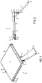
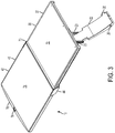
- the links 23 are designed so that when the table assembly 10 is deployed, as seen in FIGS. 1-4 , the lower and upper table assemblies 30, 40 will be oriented in a generally horizontal position while the links 23 will be oriented in a generally vertical position.
- the length of the slot 27 limits pivotal rotation of the mount portion 24 relative to the attachment portion 22 about the pivot pins 21 to approximately twenty five to thirty five degrees of rotation, preferably thirty degrees of rotation.
- the lower table assembly 30 includes a table portion 32 having an upper side with a table surface. A lower side of the table portion 32 engages an upper side of the mount portion 24 and is connected thereto by mechanical and/or chemical fasteners.
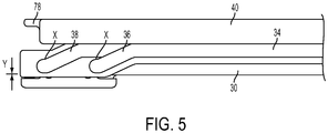
- the table portion 32 includes a pair of tracks or channels 34 with each channel 34 on an opposite side of the table portion 32 from the other. Each channel 34 has a primary track or channel 36 and a secondary track or channel 38. The primary channel 36 is recessed into the table portion 32 to a greater depth than the secondary channel 38.
- the upper table assembly 40 operationally engages the channels 34 such that the upper table assembly 40 is slidably movable relative to the lower table assembly 30.
- the upper table assembly 40 portions moves from a stowed or "stacked" position generally above and parallel to the lower table assembly 30 to a deployed position generally adjacent, aligned and co-planar with the lower table assembly 30 as the upper table assembly 40 is laterally slid away from the lower table assembly 30.
- the deployed lower and upper table assemblies 30, 40 provide a table surface area for placement of food, drink or other objects thereupon. Even in its stowed or "stacked" position, the upper table assembly 40 provides a table surface area for placement of food, drink or other objects thereupon.
- the upper table assembly 40 includes a table portion 42 having an upper side with a table surface.
- a pair of pin flanges 44 operationally engage the lower and upper table assemblies 30, 40.
- Each pin flange 44 engages the lower and upper table assemblies 30, 40 on an opposite side of the lower and upper table assemblies 30, 40 from the other pin flange 44.
- Each pin flange 44 includes at least two pins 46, 48 that engage one of the channels 34 of the lower table assembly 30.
- the pins 46, 48 are horizontally spaced apart and aligned relative to each other.
- Each pin 46, 48 has a respective roller 50, 52 placed around that pin 46, 48.
- Each pin flange 44 also includes an engagement flange 54 extending away from the main body of the pin flange 44.
- Each engagement flange 54 is insertable into a respective recess 56 on opposite sides of the upper table portion 40.
- Each engagement flange 54 includes an aperture 58 through which a fastener 59 may be passed to connect the pin flange 44 to the upper table assembly 40.
- the upper table assembly 40 includes bores (not shown) formed above and below each of the recesses 56 so that the fasteners 59 may pass from a bottom side of the table portion 42 below the recesses 56 to pass through the aperture 58 to connect the pin flanges 44 to the upper table assembly 40 (the bores not extending through to the top surface of the table portion 42).
- the pin flanges 44 may be made of single piece construction with the upper table assembly 40.
- the table surfaces of the lower and upper table assemblies 30, 40 provide a generally flat, generally continuous table surface upon which food, drink or other objects may be placed by a passenger.
- the continuity of the table surface is broken along a border 73 between the directly adjacent edges of the lower and upper table assemblies 30, 40 when the assemblies 30, 40 are horizontally co-planar.
- the top surfaces of the assemblies 30, 40 are such that the edges of the assemblies 30, 40 meet in a manner that the border 73 between the assemblies 30, 40 forms a de minimis discontinuity in the overall table surface formed by the top surfaces of the assemblies 30, 40.
- each channel 34 has a primary channel 36 and a secondary channel 38 with the primary channel 36 recessed into the table portion 32 to a greater depth than the secondary channel 38.
- Pin 46 is longer than pin 48 (i.e., pin 46 is the "tall” pin while pin 48 is the “short” pin on the pin flange 44).
- roller 50 is longer than roller 52.
- the primary channel 36 is recessed into the table portion 32 to a greater depth than the secondary channel 38, the primary channel 36 is able to receive and engage both rollers 50, 52 but only the secondary channel 38 is able to receive and engage the roller 52 (i.e., the "short” roller) as the depth of the secondary channel 38 is insufficient to accommodate the roller 50 (i.e., the "tall” roller).
- the secondary channel 38 forks from the primary channel 36 in such a manner that as the upper table assembly 40 is laterally slid away from the lower table assembly 30, the upper table assembly 40 is moved away from a stowed or "stacked" position generally above and parallel to the lower table assembly 30.
- the pins 46, 48 are spaced apart such that the roller 50 remains in the primary channel 36 and continues to do so until the roller 52 reach the end of the secondary channel 38 concurrently with the roller 50 reaching the end of the primary channel 36.
- the upper table assembly 40 is in a fully deployed position generally adjacent, generally aligned and generally co-planar with the lower table assembly 30.
- the ends of the channels 36, 38 are designed to aid in locking in the angle of the lower and upper table assemblies 30, 40 relative to each other such that the table surfaces of the lower and upper table assemblies 30, 40 provide a generally flat, generally continuous table surface upon which food, drink or other objects may be placed by a passenger when the table assembly 10 is fully deployed.
- a small flat area X a few hundredths of an inch in length (e.g ., ⁇ 0.02-0.05 inches, i.e. ⁇ 0.508-0.127 mm) that the rollers 50, 52 travel in a horizontal fashion.
- the height difference Y exists because the bottom of the end of the primary channel 36 is closer to the bottom edge of table portion 32 than the bottom of the end of the secondary channel 38.
- a lip 60 extending downward along the lower side of the upper table portion 42 extends over the channel sides of the lower table portion 32 such that the lip 60 acts as a guide, aiding in lateral movement of the upper table portion 42 relative to the lower table portion 32.
- a pair of bumpers 62 are operationally connected to the lower side of the upper table portion 42 to prevent metal to metal contact between the lower and upper table portions 32, 42 when the lower and upper table portions 32, 42 are made from metal (e.g., aluminum).
- the bumpers 62 are connected to the upper table portion 42 by fasteners 64 inserted through respective bore holes 66 in the bumpers 62. The fasteners 64 engage the lower side of the upper table portion 42 and hold the bumpers 62 in place.
- Each table portion 32, 42 includes a recess 68, 70 on a top surface thereof into which inserts 72, 74 may be placed.
- the inserts 72, 74 provide a generally flat, continuous friction surface upon which food and beverage containers or other objects may be placed, the friction provided by the surface of the insert 72, 74 reduces movement of the containers or other objects placed on the table surface.
- the top surfaces of each of the table portions 32, 42 may be formed without recesses and provide a surface with sufficient friction to reduce movement of the containers or other objects placed on the table surface.
- the table surface may include a relatively shallow cylindrical recess for placement of the base of a beverage container (e.g., a cup, a soda can or the like) therein.
- the upper table assembly 40 includes a detent 76 on a lip 78 on the table portion 42.
- the detent 76 and lip 78 aid a passenger's fingers in obtaining a firm grasp on the table portion 42 as the passenger manually slides the upper table assembly 40 away from the lower table assembly 30.
- the lower table assembly 30 includes recesses 80, 82 on the table portion 32 to aid a passenger's fingers in obtaining a firm grasp on the table portion 32 as the passenger manually pulls the table assembly 10 from its stowed position.
- the table assembly 10 is disposed within an interior of a seat console or housing.
- the deployment stages required to bring the table 10 to its fully deployed position are as follows: stowed position (table assembly 10 illustrated in phantom in FIGS. 6 and 7 ), initial deployment ( FIGS. 1, 2 , and 6-8 ), and secondary deployment ( FIGS. 3 and 9 ).
- a table assembly 10 is illustrated (in phantom lines) in a stowed position within a recess or inner cavity of a seat sidearm 92 ( FIGS. 6 and 7 ) of a passenger seat 90.
- a cover 94 on the top of the seat sidearm can be rotationally opened to provide access to the recess or inner cavity to deploy the table assembly 10 and closed when the table assembly 10 is in the stowed position within the inner cavity.
- the attachment portion 22 of the table assembly 10 operationally engages rails or tracks (not shown) within the recess or inner cavity of the seat sidearm.
- the table assembly 10 is manually lifted ( i.e., manually deployed) by a user (e.g., passenger) in a vertical orientation from within the recess in which the table assembly 10 is stowed (i.e., manually lifted in the same orientation in which the table assembly 10 is stowed) such that the table assembly 10 is in the same orientation when fully extended upwards along the tracks from the stowed position (with the upper 40 and lower 30 table assemblies still in a stacked configuration).
- the pivot cylinder 26 and cam 28 on the attachment portion 22 operationally engage the tracks, providing a pivot axis about which the attachment portion 22 can pivot relative to the seat 90 with the cam 28 limiting pivotal rotation relative to the seat 90.
- the tracks can be designed to frictionally engage the attachment portion 22 to prevent the table assembly 10 from slamming downwards into the recess or inner cavity of the seat sidearm 92 if the user accidentally lets go of the table assembly 10 during upward deployment of the table assembly 10 from the seat sidearm 92.
- the user then rotates the table assembly 10 about a horizontal axis extending through the pivot 26 until the stacked lower and upper table assemblies 30, 40 are in a horizontal position (as seen in FIGS. 1, 2 , and 6-8 ).
- the passenger pulls the upper table assembly 40 laterally away from the lower table assembly 30 in a horizontal direction (i.e., towards the left sidearm 92 if the table assembly 10 is deployed from the right sidearm 92 of the seat 90 as seen from the perspective of a seated user), with the rollers 50, 52 of the upper table assembly 40 sliding along the channel 34 in the lower table assembly 30 until the rollers 50, 52 reach the end of the channel 34 (as seen in FIGS. 3 and 9 ).
- the sidearm 92 may include a small aperture (not shown) which allows the attachment portion 22 to rotate downward into a position where the cover 94 over the recess can be closed when the table portions 30, 40 are in a deployed position.
- the table assembly 10 can be automatically deployed vertically upward from within the recess of the sidearm 92, and then manually further deployed by the user.
- an end of a laminated, rolled, constant force spring operationally engages a sidewall of the recess within the sidearm 92 while another end of the spring operationally engages the attachment portion 22.
- the attachment portion 22 includes a semi-cylindrical recess for receiving a spring drum assembly connected to the spring.
- the spring drum assembly includes a cylinder, and an axle. The spring drum assembly is connected to the attachment portion 22. When the axle is fastened in position, the spring drum is connected to the attachment portion 22 and the cylinder is rotatable about the axle.
- the spring may come in various forms including, but not limited to, two thin constant force springs placed one on top of the other and then coiled up together.
- the attachment portion 22 of the table assembly 10 operationally engages rails or tracks (not shown) within the recess such that the attachment portion 22 engages and moves back and forth vertically along the tracks.
- the attachment portion 22 includes a brake engaging the tracks, using friction to slow the attachment portion 22 as the spring pulls the attachment portion 22 vertically along the tracks.
- the table assembly 10 can be moved to a fully deployed position in the manner described above. Vertical deployment of the table assembly 10 from the stowed position within the recess is achieved by attaching an internal diameter of one end of the constant force spring to the cylinder of the spring drum.
- the spring and the spring drum cooperate to provide the constant linear force that moves the table assembly 10 along the tracks as the spring, attached on one end to the spring drum, rolls about the cylinder of the spring drum and pulls the table assembly 10 vertically upwards out of the recess.
- Application of the constant linear force provided by the spring to the table assembly 10 pulls the table assembly 10 from one end of the track to the other end.
- the brake controls the speed of the table assembly 10 along the track as the table assembly 10 travels between the ends of the tracks.
- the speed of the deployment is controlled by the brake frictionally contacting at least one of the tracks, which partially counters the pull of the spring and slows the rise of the table assembly 10 along the tracks.
- the seat 90 includes a mechanism for preventing vertical travel of the table assembly 10.
- the mechanism may come in various forms including, without limitation, a latch assembly or the like.
- the latch assembly includes a stationary, spring-loaded latch mounted on a pivot axle.
- the pivot axle extends outwardly from a base mounted to a surface. In the stowed position, the latch engages the table assembly 10. The engagement of the latch and table assembly 10 prevents the table assembly 10 from being pulled vertically upwards by the spring.
- the latch can be selectively disengaged by a mechanism, allowing the table assembly 10 to travel vertically upwards along the tracks.
- the mechanism includes a button operatively connected to the latch by a mechanical linkage.
- the linkage which, in turn, pivots the latch away from the table assembly 10, disengaging the latch from the table assembly 10 and freeing the table assembly 10 to travel along the tracks.
- the spring coils upon itself around the spring drum and causes the table assembly 10 to rise upwardly along the tracks from one end of the tracks to the other.
- the mechanism may disengage the latch and table assembly 10 by a passenger pushing downwardly on the table assembly 10 operatively connected to the latch (via the linkage) which, in turn, pivots the latch away from the table assembly 10, disengaging the latch from the table assembly 10.
- the latch will automatically pivot back to the position the latch was in when the latch engaged the table assembly 10. However, the latch will not engage the table assembly 10 as the table assembly 10 has moved away from the stowed position.
- a table assembly 100 similar in structure/function to the table assembly 10 is adapted to deploy from a seatback 96 of the passenger seat 90.
- the table assembly 100 includes a base assembly 120, a lower table assembly 130 and the upper table assembly 140.
- the table assembly 100 is at least partially stowed within a recess 98 of the seatback 96.
- the recess 98 of the seatback 96 is sized and shaped to receive at least a portion of the upper table assembly 140 of the table assembly 100.
- the recess 98 is sized and shaped to receive both the upper 140 and lower 130 table assemblies in a stacked configuration.
- the lower and upper table assemblies 130, 140 are same as/similar to in structure/function as the lower and upper table assemblies 30, 40.
- the base assembly 120 is same as/similar to in structure/function as the base assembly 20, except that the base assembly 120 is adapted to deploy from the seatback 96.
- the base assembly 120 includes an attachment portion 122 and a mount portion (not shown) pivotally engaged to the attachment portion 122 by a pair of pivot pins (not shown).
- the attachment portion 122 operationally engages the seatback 96.
- a pivot cylinder (not shown) on the attachment portion 122 operationally engages the seatback 96 and provides a pivot axis about which the attachment portion 122 can pivot relative to the seatback 96.
- a cam (not shown) on an opposite side of the attachment portion 122 (generally opposite from the pivot cylinder) operationally engages the seatback 96 and limits pivotal rotation of the attachment portion 122 relative to the seatback 96 to approximately forty degrees of rotation.
- the mount portion is further pivotally connected to the attachment portion 122 by mechanical links 123.
- Each link 123 is pivotally connected to both the mount portion and the attachment portion 122.
- the mount portion includes a pair of pins (not shown) where each pin engages an end of a respective link 123.
- Each link 123 includes a slot 127 which engages a respective pin 129 on the attachment portion 122. Each pin 129 moves along the slot 127 as the table assembly 100 is moved between stowed and deployed positions.
- the links 123 are designed so that when the table assembly 100 is deployed, as seen in FIG. 7 , the lower and upper table assemblies 130, 140 will be oriented in a generally horizontal position while the links 123 will be oriented in a generally vertical position.
- the length of the slot 127 limits pivotal rotation of the mount portion relative to the attachment portion 122 about pivot pins (not shown) to approximately thirty degrees of rotation.
- the lower table assembly 130 includes a table portion 132 having an upper side with a table surface. A lower side of the table portion 132 engages an upper side of the mount portion and is connected thereto by mechanical and/or chemical fasteners.
- the table portion 132 includes a pair of tracks or channels 134 with each channel 134 on an opposite side of the table portion 132 from the other.
- Each channel 134 has a primary track or channel 136 and a secondary track or channel 138.
- the primary channel 136 is recessed into the table portion 132 to a greater depth than the secondary channel 138.
- the upper table assembly 140 operationally engages the channels 134 such that the upper table assembly 140 is slidably movable relative to the lower table assembly 130.
- the upper table assembly 140 moves from a stowed or "stacked" position generally above and parallel to the lower table assembly 130 to a deployed position generally adjacent, aligned and co-planar with the lower table assembly 130 as the upper table assembly 140 is laterally slid away from the lower table assembly 130.
- the deployed lower and upper table assemblies 130, 140 provide a table surface area for placement of food, drink or other objects thereupon. Even in its stowed or "stacked" position, the upper table assembly 140 provides a table surface area for placement of food, drink or other objects thereupon.
- the base assembly could be eliminated in favor of a pivot at the end of the lower table assembly 130 closest to the seatback to rotate the table assembly 100 down from the stowed position and then slidingly deployed towards the passenger such that once the table assembly 100 is fully deployed, the table surfaces of the lower and upper table assemblies 130, 140 provide a generally flat, generally continuous table surface upon which food, drink or other objects may be placed by a passenger.
- the table assembly 10, 100 is contained in a space between passenger chairs, or in a space between a passenger chair and a bulkhead, and so on.
- the table assembly 10, 100 is vertically rotated out from the space in which it is stowed ( i.e., rotated about a horizontal axis).
- the table assembly 10, 100 is stowed out of sight of the passenger, and the table portions may be deployed in a manner similar to that described above.
- the table assembly 10 provides a table movable between stowed and deployed positions that virtually eliminates the chance that a video display monitor 200 will be damaged as the table is moved between the stowed and deployed positions.
- the video monitor 200 is moveable between stowed and deployed positions.
- the video monitor is shown in a deployed configuration. The sliding deployment/stowage of the lower and upper table assemblies 30, 40 relative to each other prevents damage to an already deployed video monitor 200.
- the present invention has been discussed above in connection with use on a passenger aircraft, the present invention is not limited to that environment and may also be used on passenger trains, cars, buses and other vehicles including, but not limited to, carts, carriages, and devices mounted on rails.
- the present invention is also not to be limited to use in vehicles and may be used in non-vehicle or stationary environments where it is desirable to stow and deploy a flat work surface for use in the types of activities that the flat surfaces of tables, desks, countertops or the like are typically used for.
- the claimed invention is not limited in size and may be constructed in miniature versions or for use in very large-scale applications in which the same or similar principles of operation as described above would apply.
- the length and width of the table surface areas provided by the lower 30, 130 and upper 40, 140 table assemblies are not to be construed as drawn to scale, and that the lengths/widths of the table surface areas may be adjusted in conformance with the area available for stowage/deployment of the table assemblies 10, 100.
- the figures (and various components shown therein) of the specification are not to be construed as drawn to scale.
- spatially relative terms such as “inner,” “outer,” “beneath”, “below”, “lower”, “above”, “upper” and the like, may be used herein for ease of description to describe one element or feature's relationship to another element(s) or feature(s) as illustrated in the figures.
- Spatially relative terms may be intended to encompass different orientations of the device in use or operation in addition to the orientation depicted in the figures. For example, if the device in the figures is turned over, elements described as “below” or “beneath” other elements or features would then be oriented “above” the other elements or features.
- the example term “below” can encompass both an orientation of above and below.
- the device may be otherwise oriented (rotated 90 degrees or at other orientations) and the spatially relative descriptors used herein interpreted accordingly.
Landscapes
- Engineering & Computer Science (AREA)
- Aviation & Aerospace Engineering (AREA)
- Transportation (AREA)
- Mechanical Engineering (AREA)
- Passenger Equipment (AREA)
Claims (11)
- Assemblage de table (10, 100) comprenant :une portion de table inférieure (30, 130), et une portion de table supérieure (40, 140) enclenchant de manière opérationnelle la portion de table inférieure (30, 130) ;où les portions de table supérieure (40, 140) et inférieure (30, 130) sont mobiles de façon coulissante l'une par rapport à l'autre entre une configuration en général parallèle où les portions de table inférieure (30, 130) et supérieure (40, 140) sont verticalement empilées et une configuration en général co-planaire où les portions de table inférieure (30, 130) et supérieure (40, 140) sont généralement horizontalement alignées, sur quoila portion de table inférieure (30, 130) comprend au moins un canal (34, 134), et la portion de table supérieure (40, 140) enclenche le au moins un canal (34, 134) de sorte que la portion de table supérieure (40, 140) est déplaçable entre une position en général parallèle à et supérieure à la portion de table inférieure (30, 130) et ladite position en général coplanaire avec la portion de table inférieure (40, 140),caractérisé en ce que le au moins un canal (34, 134) comprend une première portion (36, 136) et une seconde portion (38, 138), et en ce que la profondeur de canal de la première portion (36, 136) est supérieure à la profondeur de canal de la seconde portion (38, 138).
- Assemblage de table selon la revendication 1, où la portion de table supérieure (40, 140) comprend une première broche (46), et une seconde broche (48) ; et où la première portion (36, 136) enclenche les deux première et seconde broches (46, 48), et la seconde portion (38, 138) enclenche uniquement la seconde broche (48).
- Assemblage de table selon la revendication 2, où la première broche (46) est plus longue que la seconde broche (48).
- Assemblage de table selon la revendication 1, où la portion de table supérieure (40, 140) comprend au moins une broche (46, 48) enclenchant le au moins un canal (34, 134) de la portion de table Inférieure (30, 130).
- Assemblage de table selon la revendication 4, où la au moins une broche (46, 48) se déplace le long du canal (34, 134) lorsque la portion de table supérieure (40, 140) se déplace latéralement par rapport à la portion de table inférieure (30, 130).
- Assemblage de table selon la revendication 1, comprenant de plus une portion de base (20, 120), où la portion de table inférieure (30, 130) enclenche de manière opérationnelle la portion de base (20, 120) de sorte que la portion de table inférieure (30, 130) peut tourner par rapport à la portion de base (20, 120).
- Assemblage de table selon la revendication 6, où la portion de base (20, 120) comprend une portion de montage (24), et une portion de fixation (22, 122) ; où la portion de table inférieure (30, 130) enclenche de manière opérationnelle la portion de montage (24).
- Assemblage de table selon la revendication 7, où les portions de montage (24) et de fixation (22, 122) sont connectées de manière pivotante.
- Assemblage de table selon la revendication 6, où une liaison (23, 123) connecte et limite de manière opérationnelle la rotation de la portion de table inférieure (30, 130) par rapport à la portion de base (20, 120).
- Assemblage de table selon la revendication 1, où les portions de table supérieure (40, 140) et inférieure (30, 130) sont dans une orientation en général verticale dans une position rentrée, et dans une orientation en général horizontale dans une position déployée.
- Assemblage de table selon la revendication 1, où des surfaces supérieures des portions de table inférieure (30, 130) et supérieure (40, 140) forment une surface de table en général continue lorsque les portions de table inférieure (30, 130) et supérieure (40, 140) sont en général horizontalement alignées.
Applications Claiming Priority (3)
| Application Number | Priority Date | Filing Date | Title |
|---|---|---|---|
| US201261615131P | 2012-03-23 | 2012-03-23 | |
| US13/842,641 US8997660B2 (en) | 2012-03-23 | 2013-03-15 | Deployable table assembly |
| PCT/US2013/033562 WO2013142821A1 (fr) | 2012-03-23 | 2013-03-22 | Ensemble table dépliable |
Publications (3)
| Publication Number | Publication Date |
|---|---|
| EP2828162A1 EP2828162A1 (fr) | 2015-01-28 |
| EP2828162A4 EP2828162A4 (fr) | 2015-12-02 |
| EP2828162B1 true EP2828162B1 (fr) | 2018-05-02 |
Family
ID=49223379
Family Applications (1)
| Application Number | Title | Priority Date | Filing Date |
|---|---|---|---|
| EP13764077.7A Active EP2828162B1 (fr) | 2012-03-23 | 2013-03-22 | Ensemble table dépliable |
Country Status (3)
| Country | Link |
|---|---|
| US (1) | US8997660B2 (fr) |
| EP (1) | EP2828162B1 (fr) |
| WO (1) | WO2013142821A1 (fr) |
Families Citing this family (29)
| Publication number | Priority date | Publication date | Assignee | Title |
|---|---|---|---|---|
| SG2013052030A (en) * | 2013-07-04 | 2015-02-27 | Singapore Tech Aerospace Ltd | A seatback for a passenger seat |
| DE102013021077A1 (de) * | 2013-12-18 | 2015-06-18 | Lisa Dräxlmaier GmbH | Tischerweiterung für einen Flugzeugtisch |
| DE202014101544U1 (de) * | 2014-04-01 | 2014-05-19 | Zim Flugsitz Gmbh | Haltevorrichtung für eine Anzeige und/oder Bedieneinheit zur Anbringung in einem Flugzeug sowie Anzeige- und Bedienvorrichtung mit einer Haltevorrichtung |
| US9919802B2 (en) | 2014-04-07 | 2018-03-20 | B/E Aerospace, Inc. | Laterally-expanding tray table |
| EP3128873B1 (fr) * | 2014-04-07 | 2018-09-26 | B/E Aerospace, Inc. | Table à plateau extensible latéralement |
| US9332835B2 (en) * | 2014-08-14 | 2016-05-10 | John Gregory Shannon | Portable desk |
| US10196147B2 (en) | 2015-09-11 | 2019-02-05 | Safran Seats Usa Llc | Front row module |
| US9849819B2 (en) * | 2016-02-26 | 2017-12-26 | Ford Global Technologies, Llc | Hidden foldable tray table |
| EP3213994A1 (fr) * | 2016-03-03 | 2017-09-06 | Zodiac Seats UK Limited | Table-plateau à lames multiples |
| WO2017176722A1 (fr) * | 2016-04-04 | 2017-10-12 | B/E Aerospace, Inc. | Table-plateau déployable à partir d'une zone de dossier inférieure |
| US9986842B1 (en) * | 2016-05-20 | 2018-06-05 | Allison Pia Belcher | Portable hand-wrapping platform |
| US20180238041A1 (en) | 2017-02-21 | 2018-08-23 | Styrc Jacek | Modular furniture system |
| US10426258B2 (en) * | 2017-07-06 | 2019-10-01 | Safran Seats Usa Llc | Sliding mechanism |
| US10442537B2 (en) | 2017-07-20 | 2019-10-15 | Johnny A. Satterfield | Deployable table assembly |
| USD834852S1 (en) * | 2017-12-13 | 2018-12-04 | Bradford L. Davis | Overbed table |
| US10625649B2 (en) * | 2018-04-10 | 2020-04-21 | B/E Aerospace, Inc. | Mechanism to achieve expandable tray table |
| US10864991B2 (en) * | 2019-03-20 | 2020-12-15 | B/E Aerospace, Inc. | Adjustable cantilevered table assembly |
| CN112406657B (zh) * | 2019-08-21 | 2022-07-19 | Oppo广东移动通信有限公司 | 智能桌 |
| USD952382S1 (en) * | 2020-02-04 | 2022-05-24 | 2724889 Ontario Inc. | Table |
| DE102020106029A1 (de) * | 2020-03-05 | 2021-09-09 | Zim Flugsitz Gmbh | Fluggastsitz und Sitzreihe |
| US11565818B2 (en) * | 2020-04-13 | 2023-01-31 | Adient Aerospace, Llc | Tray table apparatus for a console element, console element and seat unit |
| USD938068S1 (en) | 2020-08-12 | 2021-12-07 | 2724889 Ontario Inc. | Connector for a modular structure |
| US11827360B2 (en) * | 2020-09-25 | 2023-11-28 | S & S Numerical Control, Inc. | Slide-out tray table with interlock assembly |
| CN114408187A (zh) * | 2020-09-25 | 2022-04-29 | 安道拓航空航天公司 | 具有互锁组件的滑出式托盘桌 |
| JP7123102B2 (ja) * | 2020-10-07 | 2022-08-22 | 本田技研工業株式会社 | シート用テーブル |
| JP7112465B2 (ja) * | 2020-10-07 | 2022-08-03 | 本田技研工業株式会社 | シート用テーブル |
| US11607980B2 (en) * | 2021-02-10 | 2023-03-21 | Ford Global Technologies, Llc | Seat assembly with deployable panel |
| US11932403B2 (en) * | 2022-01-10 | 2024-03-19 | Safran Seats Usa Llc | Tray table with honeycomb core |
| US11918117B2 (en) | 2022-05-18 | 2024-03-05 | B/E Aerospace, Inc. | Convertible closet with articulating top shelf |
Citations (1)
| Publication number | Priority date | Publication date | Assignee | Title |
|---|---|---|---|---|
| KR200189971Y1 (ko) * | 1997-08-30 | 2000-08-01 | 정몽규 | 휴식테이블 겸용 도어 암레스트 구조 |
Family Cites Families (25)
| Publication number | Priority date | Publication date | Assignee | Title |
|---|---|---|---|---|
| DE2119052A1 (de) * | 1971-04-20 | 1972-11-02 | Fa. Hugo Guide, 7031 Holzgerlingen | Auszugtischplatte für eine Schrankwand |
| DE2263073C2 (de) * | 1972-12-22 | 1982-11-25 | Robert Krause KG Zweigniederlassung Weilheim/Teck, 7315 Weilheim | Ausziehbeschlag für eine erste Platte und eine zweite Platte, wie einer Tisch- oder Arbeitsplatte |
| US3899982A (en) * | 1974-01-28 | 1975-08-19 | Richard J Fetzek | Pull out table for attachment beneath an automobile dashboard |
| US4159071A (en) | 1978-01-27 | 1979-06-26 | Hank Roca | Pivotable utility table |
| US4174669A (en) * | 1978-02-22 | 1979-11-20 | Lalonde A Roger | Vehicle tray and mounting bracket assembly |
| FR2450084A1 (fr) * | 1979-03-01 | 1980-09-26 | Kempf Bertrand | Table transformable, notamment pour jeux |
| US4944552A (en) * | 1989-03-17 | 1990-07-31 | Weber Aircraft, Inc. | Stowable table system |
| US5140914A (en) * | 1991-10-07 | 1992-08-25 | Marc Bohbot | Vehicle seat tray |
| US5370060A (en) * | 1993-06-11 | 1994-12-06 | Wang; Liwen Y. | Multipurpose automobile foldaway table |
| US5540158A (en) * | 1994-08-29 | 1996-07-30 | Ford; Henry E. | Sectional folding table |
| US5709155A (en) * | 1995-01-12 | 1998-01-20 | Mul Acquisition Corp. Ii | Folding tray table for chairs |
| KR100194872B1 (ko) | 1996-11-11 | 1999-06-15 | 정몽규 | 가변식 파이프 고정 지그 |
| KR19980035029U (ko) * | 1996-12-12 | 1998-09-15 | 박병재 | 시트용 간이 테이블 |
| US6161486A (en) * | 1999-11-12 | 2000-12-19 | Boots; Andrew P. | Foldable and extendable bench |
| US6488248B1 (en) * | 2000-05-09 | 2002-12-03 | Weber Knapp Company | Keyboard mechanism tracking system |
| US6761398B2 (en) * | 2001-05-25 | 2004-07-13 | Weber Aircraft Lp | Stowable tables |
| US6454349B1 (en) * | 2001-07-27 | 2002-09-24 | The Boeing Company | Pivoting tray table assembly |
| US7523905B2 (en) * | 2006-01-20 | 2009-04-28 | Workrite Ergonomics, Inc. | Height and tilt adjustable keyboard support |
| US7675742B2 (en) * | 2006-02-22 | 2010-03-09 | ATEN International Co, Ltd | Rack-mounted KVM module with positioning mechanism |
| US7281762B1 (en) * | 2006-08-11 | 2007-10-16 | Kenneth Getfield | Portable platforms and methods of use |
| US7806305B1 (en) * | 2007-02-08 | 2010-10-05 | Moore Jr Nathaniel | Travel tray |
| USD575546S1 (en) * | 2007-09-21 | 2008-08-26 | Honda Motor Co., Ltd. | Folding table |
| US7963231B2 (en) * | 2007-09-21 | 2011-06-21 | Honda Motor Co., Ltd. | Folding table and support frame assembly |
| US7506923B1 (en) | 2008-04-10 | 2009-03-24 | Be Aerospace, Inc. | Adjustable bi-fold tray table |
| IT1399460B1 (it) * | 2010-04-13 | 2013-04-19 | Naos Srl | Tavolo allungabile. |
-
2013
- 2013-03-15 US US13/842,641 patent/US8997660B2/en active Active - Reinstated
- 2013-03-22 WO PCT/US2013/033562 patent/WO2013142821A1/fr not_active Ceased
- 2013-03-22 EP EP13764077.7A patent/EP2828162B1/fr active Active
Patent Citations (1)
| Publication number | Priority date | Publication date | Assignee | Title |
|---|---|---|---|---|
| KR200189971Y1 (ko) * | 1997-08-30 | 2000-08-01 | 정몽규 | 휴식테이블 겸용 도어 암레스트 구조 |
Also Published As
| Publication number | Publication date |
|---|---|
| EP2828162A4 (fr) | 2015-12-02 |
| US20130284074A1 (en) | 2013-10-31 |
| US8997660B2 (en) | 2015-04-07 |
| WO2013142821A1 (fr) | 2013-09-26 |
| EP2828162A1 (fr) | 2015-01-28 |
Similar Documents
| Publication | Publication Date | Title |
|---|---|---|
| US8997660B2 (en) | Deployable table assembly | |
| CN104284837B (zh) | 悬臂托盘桌以及包括该悬臂托盘桌的飞机乘客套间 | |
| EP3313733B1 (fr) | Ensemble table pour siège de passager | |
| EP2799338B1 (fr) | Table à plateau configurable | |
| US10414313B2 (en) | Hidden foldable tray table | |
| US10279916B2 (en) | Center console side opening doors and integrated armrest cocktail tray | |
| US20210101683A1 (en) | Seat system with stowable tray | |
| EP3498605B1 (fr) | Modules de commodités | |
| US10442537B2 (en) | Deployable table assembly | |
| EP3213994A1 (fr) | Table-plateau à lames multiples | |
| WO2020263266A1 (fr) | Support de dispositif électronique portable pour siège | |
| WO2017087602A1 (fr) | Table-plateau et support de dispositif électronique personnel de table-plateau d'une seule pièce | |
| US20210339870A1 (en) | Aircraft tray table with magnification lens | |
| EP3350022A1 (fr) | Support de dispositif électronique portatif pour tables-plateaux | |
| WO2020222193A1 (fr) | Zone de cabine multifonctionnelle | |
| EP3221188B1 (fr) | Siège de véhicule comprenant un support intégré pour dispositifs électroniques | |
| US20230415898A1 (en) | Aircraft seat design with mountable food tray | |
| CN111071452B (zh) | 具有臂内杯架的扶手组件 | |
| US10259368B2 (en) | Articulating armrest | |
| EP3819216A1 (fr) | Fermeture permettant l'intimité de siège monté sur une barre d'écartement de siège | |
| US11858427B2 (en) | PED holder arm concept | |
| EP4538175A1 (fr) | Table à plateaux avec appareil de positionnement de dispositif électronique |
Legal Events
| Date | Code | Title | Description |
|---|---|---|---|
| PUAI | Public reference made under article 153(3) epc to a published international application that has entered the european phase |
Free format text: ORIGINAL CODE: 0009012 |
|
| 17P | Request for examination filed |
Effective date: 20141023 |
|
| AK | Designated contracting states |
Kind code of ref document: A1 Designated state(s): AL AT BE BG CH CY CZ DE DK EE ES FI FR GB GR HR HU IE IS IT LI LT LU LV MC MK MT NL NO PL PT RO RS SE SI SK SM TR |
|
| AX | Request for extension of the european patent |
Extension state: BA ME |
|
| DAX | Request for extension of the european patent (deleted) | ||
| RA4 | Supplementary search report drawn up and despatched (corrected) |
Effective date: 20151102 |
|
| RIC1 | Information provided on ipc code assigned before grant |
Ipc: A47B 3/00 20060101ALI20151027BHEP Ipc: B64D 11/06 20060101AFI20151027BHEP Ipc: A47B 13/08 20060101ALI20151027BHEP Ipc: A47B 1/10 20060101ALI20151027BHEP Ipc: A47B 31/06 20060101ALI20151027BHEP Ipc: B60N 3/00 20060101ALI20151027BHEP |
|
| STAA | Information on the status of an ep patent application or granted ep patent |
Free format text: STATUS: EXAMINATION IS IN PROGRESS |
|
| 17Q | First examination report despatched |
Effective date: 20170522 |
|
| REG | Reference to a national code |
Ref country code: DE Ref legal event code: R079 Ref document number: 602013036924 Country of ref document: DE Free format text: PREVIOUS MAIN CLASS: B64D0011060000 Ipc: A47B0005000000 |
|
| GRAP | Despatch of communication of intention to grant a patent |
Free format text: ORIGINAL CODE: EPIDOSNIGR1 |
|
| STAA | Information on the status of an ep patent application or granted ep patent |
Free format text: STATUS: GRANT OF PATENT IS INTENDED |
|
| RIC1 | Information provided on ipc code assigned before grant |
Ipc: B64D 11/00 20060101ALI20171006BHEP Ipc: A47B 5/00 20060101AFI20171006BHEP Ipc: B60N 3/00 20060101ALI20171006BHEP Ipc: B64D 11/06 20060101ALI20171006BHEP Ipc: A47B 31/06 20060101ALI20171006BHEP Ipc: A47B 13/08 20060101ALI20171006BHEP Ipc: A47B 1/10 20060101ALI20171006BHEP |
|
| INTG | Intention to grant announced |
Effective date: 20171114 |
|
| GRAS | Grant fee paid |
Free format text: ORIGINAL CODE: EPIDOSNIGR3 |
|
| GRAA | (expected) grant |
Free format text: ORIGINAL CODE: 0009210 |
|
| STAA | Information on the status of an ep patent application or granted ep patent |
Free format text: STATUS: THE PATENT HAS BEEN GRANTED |
|
| AK | Designated contracting states |
Kind code of ref document: B1 Designated state(s): AL AT BE BG CH CY CZ DE DK EE ES FI FR GB GR HR HU IE IS IT LI LT LU LV MC MK MT NL NO PL PT RO RS SE SI SK SM TR |
|
| REG | Reference to a national code |
Ref country code: GB Ref legal event code: FG4D |
|
| REG | Reference to a national code |
Ref country code: CH Ref legal event code: EP Ref country code: AT Ref legal event code: REF Ref document number: 994322 Country of ref document: AT Kind code of ref document: T Effective date: 20180515 |
|
| REG | Reference to a national code |
Ref country code: DE Ref legal event code: R096 Ref document number: 602013036924 Country of ref document: DE |
|
| REG | Reference to a national code |
Ref country code: IE Ref legal event code: FG4D |
|
| REG | Reference to a national code |
Ref country code: NL Ref legal event code: FP |
|
| REG | Reference to a national code |
Ref country code: LT Ref legal event code: MG4D |
|
| PG25 | Lapsed in a contracting state [announced via postgrant information from national office to epo] |
Ref country code: FI Free format text: LAPSE BECAUSE OF FAILURE TO SUBMIT A TRANSLATION OF THE DESCRIPTION OR TO PAY THE FEE WITHIN THE PRESCRIBED TIME-LIMIT Effective date: 20180502 Ref country code: BG Free format text: LAPSE BECAUSE OF FAILURE TO SUBMIT A TRANSLATION OF THE DESCRIPTION OR TO PAY THE FEE WITHIN THE PRESCRIBED TIME-LIMIT Effective date: 20180802 Ref country code: SE Free format text: LAPSE BECAUSE OF FAILURE TO SUBMIT A TRANSLATION OF THE DESCRIPTION OR TO PAY THE FEE WITHIN THE PRESCRIBED TIME-LIMIT Effective date: 20180502 Ref country code: NO Free format text: LAPSE BECAUSE OF FAILURE TO SUBMIT A TRANSLATION OF THE DESCRIPTION OR TO PAY THE FEE WITHIN THE PRESCRIBED TIME-LIMIT Effective date: 20180802 Ref country code: ES Free format text: LAPSE BECAUSE OF FAILURE TO SUBMIT A TRANSLATION OF THE DESCRIPTION OR TO PAY THE FEE WITHIN THE PRESCRIBED TIME-LIMIT Effective date: 20180502 Ref country code: LT Free format text: LAPSE BECAUSE OF FAILURE TO SUBMIT A TRANSLATION OF THE DESCRIPTION OR TO PAY THE FEE WITHIN THE PRESCRIBED TIME-LIMIT Effective date: 20180502 |
|
| PG25 | Lapsed in a contracting state [announced via postgrant information from national office to epo] |
Ref country code: HR Free format text: LAPSE BECAUSE OF FAILURE TO SUBMIT A TRANSLATION OF THE DESCRIPTION OR TO PAY THE FEE WITHIN THE PRESCRIBED TIME-LIMIT Effective date: 20180502 Ref country code: RS Free format text: LAPSE BECAUSE OF FAILURE TO SUBMIT A TRANSLATION OF THE DESCRIPTION OR TO PAY THE FEE WITHIN THE PRESCRIBED TIME-LIMIT Effective date: 20180502 Ref country code: GR Free format text: LAPSE BECAUSE OF FAILURE TO SUBMIT A TRANSLATION OF THE DESCRIPTION OR TO PAY THE FEE WITHIN THE PRESCRIBED TIME-LIMIT Effective date: 20180803 Ref country code: LV Free format text: LAPSE BECAUSE OF FAILURE TO SUBMIT A TRANSLATION OF THE DESCRIPTION OR TO PAY THE FEE WITHIN THE PRESCRIBED TIME-LIMIT Effective date: 20180502 |
|
| REG | Reference to a national code |
Ref country code: AT Ref legal event code: MK05 Ref document number: 994322 Country of ref document: AT Kind code of ref document: T Effective date: 20180502 |
|
| PG25 | Lapsed in a contracting state [announced via postgrant information from national office to epo] |
Ref country code: EE Free format text: LAPSE BECAUSE OF FAILURE TO SUBMIT A TRANSLATION OF THE DESCRIPTION OR TO PAY THE FEE WITHIN THE PRESCRIBED TIME-LIMIT Effective date: 20180502 Ref country code: SK Free format text: LAPSE BECAUSE OF FAILURE TO SUBMIT A TRANSLATION OF THE DESCRIPTION OR TO PAY THE FEE WITHIN THE PRESCRIBED TIME-LIMIT Effective date: 20180502 Ref country code: AT Free format text: LAPSE BECAUSE OF FAILURE TO SUBMIT A TRANSLATION OF THE DESCRIPTION OR TO PAY THE FEE WITHIN THE PRESCRIBED TIME-LIMIT Effective date: 20180502 Ref country code: DK Free format text: LAPSE BECAUSE OF FAILURE TO SUBMIT A TRANSLATION OF THE DESCRIPTION OR TO PAY THE FEE WITHIN THE PRESCRIBED TIME-LIMIT Effective date: 20180502 Ref country code: CZ Free format text: LAPSE BECAUSE OF FAILURE TO SUBMIT A TRANSLATION OF THE DESCRIPTION OR TO PAY THE FEE WITHIN THE PRESCRIBED TIME-LIMIT Effective date: 20180502 Ref country code: RO Free format text: LAPSE BECAUSE OF FAILURE TO SUBMIT A TRANSLATION OF THE DESCRIPTION OR TO PAY THE FEE WITHIN THE PRESCRIBED TIME-LIMIT Effective date: 20180502 Ref country code: PL Free format text: LAPSE BECAUSE OF FAILURE TO SUBMIT A TRANSLATION OF THE DESCRIPTION OR TO PAY THE FEE WITHIN THE PRESCRIBED TIME-LIMIT Effective date: 20180502 |
|
| REG | Reference to a national code |
Ref country code: DE Ref legal event code: R097 Ref document number: 602013036924 Country of ref document: DE |
|
| PG25 | Lapsed in a contracting state [announced via postgrant information from national office to epo] |
Ref country code: SM Free format text: LAPSE BECAUSE OF FAILURE TO SUBMIT A TRANSLATION OF THE DESCRIPTION OR TO PAY THE FEE WITHIN THE PRESCRIBED TIME-LIMIT Effective date: 20180502 |
|
| PLBE | No opposition filed within time limit |
Free format text: ORIGINAL CODE: 0009261 |
|
| STAA | Information on the status of an ep patent application or granted ep patent |
Free format text: STATUS: NO OPPOSITION FILED WITHIN TIME LIMIT |
|
| 26N | No opposition filed |
Effective date: 20190205 |
|
| PG25 | Lapsed in a contracting state [announced via postgrant information from national office to epo] |
Ref country code: SI Free format text: LAPSE BECAUSE OF FAILURE TO SUBMIT A TRANSLATION OF THE DESCRIPTION OR TO PAY THE FEE WITHIN THE PRESCRIBED TIME-LIMIT Effective date: 20180502 |
|
| PG25 | Lapsed in a contracting state [announced via postgrant information from national office to epo] |
Ref country code: MC Free format text: LAPSE BECAUSE OF FAILURE TO SUBMIT A TRANSLATION OF THE DESCRIPTION OR TO PAY THE FEE WITHIN THE PRESCRIBED TIME-LIMIT Effective date: 20180502 |
|
| PG25 | Lapsed in a contracting state [announced via postgrant information from national office to epo] |
Ref country code: AL Free format text: LAPSE BECAUSE OF FAILURE TO SUBMIT A TRANSLATION OF THE DESCRIPTION OR TO PAY THE FEE WITHIN THE PRESCRIBED TIME-LIMIT Effective date: 20180502 Ref country code: LU Free format text: LAPSE BECAUSE OF NON-PAYMENT OF DUE FEES Effective date: 20190322 |
|
| REG | Reference to a national code |
Ref country code: BE Ref legal event code: MM Effective date: 20190331 |
|
| PG25 | Lapsed in a contracting state [announced via postgrant information from national office to epo] |
Ref country code: BE Free format text: LAPSE BECAUSE OF NON-PAYMENT OF DUE FEES Effective date: 20190331 |
|
| PG25 | Lapsed in a contracting state [announced via postgrant information from national office to epo] |
Ref country code: TR Free format text: LAPSE BECAUSE OF FAILURE TO SUBMIT A TRANSLATION OF THE DESCRIPTION OR TO PAY THE FEE WITHIN THE PRESCRIBED TIME-LIMIT Effective date: 20180502 |
|
| PG25 | Lapsed in a contracting state [announced via postgrant information from national office to epo] |
Ref country code: PT Free format text: LAPSE BECAUSE OF FAILURE TO SUBMIT A TRANSLATION OF THE DESCRIPTION OR TO PAY THE FEE WITHIN THE PRESCRIBED TIME-LIMIT Effective date: 20180903 Ref country code: MT Free format text: LAPSE BECAUSE OF NON-PAYMENT OF DUE FEES Effective date: 20190322 |
|
| REG | Reference to a national code |
Ref country code: DE Ref legal event code: R082 Ref document number: 602013036924 Country of ref document: DE Representative=s name: STOLMAR & PARTNER PATENTANWAELTE PARTG MBB, DE |
|
| PGFP | Annual fee paid to national office [announced via postgrant information from national office to epo] |
Ref country code: CH Payment date: 20210317 Year of fee payment: 9 |
|
| PG25 | Lapsed in a contracting state [announced via postgrant information from national office to epo] |
Ref country code: CY Free format text: LAPSE BECAUSE OF FAILURE TO SUBMIT A TRANSLATION OF THE DESCRIPTION OR TO PAY THE FEE WITHIN THE PRESCRIBED TIME-LIMIT Effective date: 20180502 |
|
| PG25 | Lapsed in a contracting state [announced via postgrant information from national office to epo] |
Ref country code: IS Free format text: LAPSE BECAUSE OF FAILURE TO SUBMIT A TRANSLATION OF THE DESCRIPTION OR TO PAY THE FEE WITHIN THE PRESCRIBED TIME-LIMIT Effective date: 20180902 |
|
| PG25 | Lapsed in a contracting state [announced via postgrant information from national office to epo] |
Ref country code: HU Free format text: LAPSE BECAUSE OF FAILURE TO SUBMIT A TRANSLATION OF THE DESCRIPTION OR TO PAY THE FEE WITHIN THE PRESCRIBED TIME-LIMIT; INVALID AB INITIO Effective date: 20130322 |
|
| PG25 | Lapsed in a contracting state [announced via postgrant information from national office to epo] |
Ref country code: MK Free format text: LAPSE BECAUSE OF FAILURE TO SUBMIT A TRANSLATION OF THE DESCRIPTION OR TO PAY THE FEE WITHIN THE PRESCRIBED TIME-LIMIT Effective date: 20180502 |
|
| REG | Reference to a national code |
Ref country code: CH Ref legal event code: PL |
|
| PG25 | Lapsed in a contracting state [announced via postgrant information from national office to epo] |
Ref country code: LI Free format text: LAPSE BECAUSE OF NON-PAYMENT OF DUE FEES Effective date: 20220331 Ref country code: CH Free format text: LAPSE BECAUSE OF NON-PAYMENT OF DUE FEES Effective date: 20220331 |
|
| PGFP | Annual fee paid to national office [announced via postgrant information from national office to epo] |
Ref country code: FR Payment date: 20251231 Year of fee payment: 14 |
|
| PGFP | Annual fee paid to national office [announced via postgrant information from national office to epo] |
Ref country code: NL Payment date: 20260106 Year of fee payment: 14 |
|
| PGFP | Annual fee paid to national office [announced via postgrant information from national office to epo] |
Ref country code: GB Payment date: 20260106 Year of fee payment: 14 |
|
| PGFP | Annual fee paid to national office [announced via postgrant information from national office to epo] |
Ref country code: IE Payment date: 20260102 Year of fee payment: 14 Ref country code: DE Payment date: 20260102 Year of fee payment: 14 |
|
| PGFP | Annual fee paid to national office [announced via postgrant information from national office to epo] |
Ref country code: IT Payment date: 20260220 Year of fee payment: 14 |