EP2828537B1 - Actionneur bistable, ensemble d'actionneurs, méthode d'actionnement et utilisation - Google Patents
Actionneur bistable, ensemble d'actionneurs, méthode d'actionnement et utilisation Download PDFInfo
- Publication number
- EP2828537B1 EP2828537B1 EP13705390.6A EP13705390A EP2828537B1 EP 2828537 B1 EP2828537 B1 EP 2828537B1 EP 13705390 A EP13705390 A EP 13705390A EP 2828537 B1 EP2828537 B1 EP 2828537B1
- Authority
- EP
- European Patent Office
- Prior art keywords
- actuator
- fluid supply
- sealing medium
- sealing
- chamber
- Prior art date
- Legal status (The legal status is an assumption and is not a legal conclusion. Google has not performed a legal analysis and makes no representation as to the accuracy of the status listed.)
- Active
Links
Images

Classifications
-
- F—MECHANICAL ENGINEERING; LIGHTING; HEATING; WEAPONS; BLASTING
- F15—FLUID-PRESSURE ACTUATORS; HYDRAULICS OR PNEUMATICS IN GENERAL
- F15B—SYSTEMS ACTING BY MEANS OF FLUIDS IN GENERAL; FLUID-PRESSURE ACTUATORS, e.g. SERVOMOTORS; DETAILS OF FLUID-PRESSURE SYSTEMS, NOT OTHERWISE PROVIDED FOR
- F15B15/00—Fluid-actuated devices for displacing a member from one position to another; Gearing associated therewith
- F15B15/08—Characterised by the construction of the motor unit
- F15B15/10—Characterised by the construction of the motor unit the motor being of diaphragm type
-
- F—MECHANICAL ENGINEERING; LIGHTING; HEATING; WEAPONS; BLASTING
- F02—COMBUSTION ENGINES; HOT-GAS OR COMBUSTION-PRODUCT ENGINE PLANTS
- F02B—INTERNAL-COMBUSTION PISTON ENGINES; COMBUSTION ENGINES IN GENERAL
- F02B75/00—Other engines
- F02B75/36—Engines with parts of combustion- or working-chamber walls resiliently yielding under pressure
- F02B75/38—Reciprocating - piston engines
-
- F—MECHANICAL ENGINEERING; LIGHTING; HEATING; WEAPONS; BLASTING
- F02—COMBUSTION ENGINES; HOT-GAS OR COMBUSTION-PRODUCT ENGINE PLANTS
- F02F—CYLINDERS, PISTONS OR CASINGS, FOR COMBUSTION ENGINES; ARRANGEMENTS OF SEALINGS IN COMBUSTION ENGINES
- F02F3/00—Pistons
-
- F—MECHANICAL ENGINEERING; LIGHTING; HEATING; WEAPONS; BLASTING
- F02—COMBUSTION ENGINES; HOT-GAS OR COMBUSTION-PRODUCT ENGINE PLANTS
- F02F—CYLINDERS, PISTONS OR CASINGS, FOR COMBUSTION ENGINES; ARRANGEMENTS OF SEALINGS IN COMBUSTION ENGINES
- F02F3/00—Pistons
- F02F3/0015—Multi-part pistons
-
- F—MECHANICAL ENGINEERING; LIGHTING; HEATING; WEAPONS; BLASTING
- F15—FLUID-PRESSURE ACTUATORS; HYDRAULICS OR PNEUMATICS IN GENERAL
- F15B—SYSTEMS ACTING BY MEANS OF FLUIDS IN GENERAL; FLUID-PRESSURE ACTUATORS, e.g. SERVOMOTORS; DETAILS OF FLUID-PRESSURE SYSTEMS, NOT OTHERWISE PROVIDED FOR
- F15B15/00—Fluid-actuated devices for displacing a member from one position to another; Gearing associated therewith
- F15B15/08—Characterised by the construction of the motor unit
- F15B15/14—Characterised by the construction of the motor unit of the straight-cylinder type
- F15B15/1404—Characterised by the construction of the motor unit of the straight-cylinder type in clusters, e.g. multiple cylinders in one block
-
- F—MECHANICAL ENGINEERING; LIGHTING; HEATING; WEAPONS; BLASTING
- F16—ENGINEERING ELEMENTS AND UNITS; GENERAL MEASURES FOR PRODUCING AND MAINTAINING EFFECTIVE FUNCTIONING OF MACHINES OR INSTALLATIONS; THERMAL INSULATION IN GENERAL
- F16K—VALVES; TAPS; COCKS; ACTUATING-FLOATS; DEVICES FOR VENTING OR AERATING
- F16K99/00—Subject matter not provided for in other groups of this subclass
- F16K99/0001—Microvalves
- F16K99/0003—Constructional types of microvalves; Details of the cutting-off member
- F16K99/0032—Constructional types of microvalves; Details of the cutting-off member using phase transition or influencing viscosity
-
- F—MECHANICAL ENGINEERING; LIGHTING; HEATING; WEAPONS; BLASTING
- F16—ENGINEERING ELEMENTS AND UNITS; GENERAL MEASURES FOR PRODUCING AND MAINTAINING EFFECTIVE FUNCTIONING OF MACHINES OR INSTALLATIONS; THERMAL INSULATION IN GENERAL
- F16K—VALVES; TAPS; COCKS; ACTUATING-FLOATS; DEVICES FOR VENTING OR AERATING
- F16K99/00—Subject matter not provided for in other groups of this subclass
- F16K99/0001—Microvalves
- F16K99/0034—Operating means specially adapted for microvalves
- F16K99/0042—Electric operating means therefor
- F16K99/0044—Electric operating means therefor using thermo-electric means
-
- F—MECHANICAL ENGINEERING; LIGHTING; HEATING; WEAPONS; BLASTING
- F16—ENGINEERING ELEMENTS AND UNITS; GENERAL MEASURES FOR PRODUCING AND MAINTAINING EFFECTIVE FUNCTIONING OF MACHINES OR INSTALLATIONS; THERMAL INSULATION IN GENERAL
- F16K—VALVES; TAPS; COCKS; ACTUATING-FLOATS; DEVICES FOR VENTING OR AERATING
- F16K99/00—Subject matter not provided for in other groups of this subclass
- F16K99/0001—Microvalves
- F16K99/0034—Operating means specially adapted for microvalves
- F16K99/0055—Operating means specially adapted for microvalves actuated by fluids
- F16K99/0061—Operating means specially adapted for microvalves actuated by fluids actuated by an expanding gas or liquid volume
-
- G—PHYSICS
- G09—EDUCATION; CRYPTOGRAPHY; DISPLAY; ADVERTISING; SEALS
- G09B—EDUCATIONAL OR DEMONSTRATION APPLIANCES; APPLIANCES FOR TEACHING, OR COMMUNICATING WITH, THE BLIND, DEAF OR MUTE; MODELS; PLANETARIA; GLOBES; MAPS; DIAGRAMS
- G09B21/00—Teaching, or communicating with, the blind, deaf or mute
- G09B21/001—Teaching or communicating with blind persons
- G09B21/003—Teaching or communicating with blind persons using tactile presentation of the information, e.g. Braille displays
- G09B21/004—Details of particular tactile cells, e.g. electro-mechanical or mechanical layout
-
- F—MECHANICAL ENGINEERING; LIGHTING; HEATING; WEAPONS; BLASTING
- F16—ENGINEERING ELEMENTS AND UNITS; GENERAL MEASURES FOR PRODUCING AND MAINTAINING EFFECTIVE FUNCTIONING OF MACHINES OR INSTALLATIONS; THERMAL INSULATION IN GENERAL
- F16K—VALVES; TAPS; COCKS; ACTUATING-FLOATS; DEVICES FOR VENTING OR AERATING
- F16K99/00—Subject matter not provided for in other groups of this subclass
- F16K99/0001—Microvalves
- F16K2099/0069—Bistable microvalves
-
- Y—GENERAL TAGGING OF NEW TECHNOLOGICAL DEVELOPMENTS; GENERAL TAGGING OF CROSS-SECTIONAL TECHNOLOGIES SPANNING OVER SEVERAL SECTIONS OF THE IPC; TECHNICAL SUBJECTS COVERED BY FORMER USPC CROSS-REFERENCE ART COLLECTIONS [XRACs] AND DIGESTS
- Y10—TECHNICAL SUBJECTS COVERED BY FORMER USPC
- Y10T—TECHNICAL SUBJECTS COVERED BY FORMER US CLASSIFICATION
- Y10T137/00—Fluid handling
- Y10T137/0318—Processes
Definitions
- the invention relates to a bistable actuator, an actuator arrangement, a method for actuating and a use of the actuator arrangement.
- linear actuator strokes are particularly important in microsystem technology. Such linear actuator strokes can be used for the precise positioning of components in optics, in sensors or comparable systems.
- the selection of a suitable actuator is usually made taking into account boundary conditions, such as the achievable signal pressure, the travel and the positioning accuracy.
- the pamphlet US 2004/0124384 A1 discloses a pneumatic actuator having an elastomeric diaphragm and an electrostatic flap valve assembly.
- An electrostatically operated actuator is also in Levent Yobas et al .: "A Novel Bulk-Micromachined Electrostatic Microvalve with a Curved-Compliant Structure Applicable for a Pneumatic Tactile Display", Journal of microelecromechanical systems, IEEE Service Center, US, Vol. 10, No. 2, June 1 2001, ISSN: 1057-7157 described.
- the pamphlet WO 00/22598 A1 discloses a configurable Braille display with a plurality of individually addressable points.
- the actuators used are also based on electrostatically actuated membranes.
- the pamphlet US 2003/019522 A1 discloses a valve for use in a microfluidic system wherein a thermally responsive substance is used to actuate the valve.
- the pamphlet US 2006/219308 A1 discloses a microvalve used to control magnetic wax is used in the valve.
- the pressure-tight closing of the actuator fluid supply connection advantageously has the effect that the working pressure in the actuator chamber is maintained regardless of whether an overpressure is applied in the actuator fluid supply.
- the overpressure in the actuator fluid supply which was required to generate the working overpressure in the actuator chamber, whereby the actuator element was transferred from the rest position to the actuation position, can still be present or no longer present.
- the excess pressure in the actuator fluid supply can advantageously be released.
- the bistable actuation of the actuator therefore only requires energy to change the position of the actuator element from the rest position to the actuation position.
- the actuator element In the idle state of the actuator, the actuator element is in the idle position and is held there in a stable manner without any further energy supply to the actuator.
- the actuator element In the actuation state of the actuator, the actuator element is in the actuation position and is held there in a stable manner without any further energy supply to the actuator.
- the rest position and the actuation position are advantageously both stable without any additional energy supply.
- the actuator is a fluidic or microfluidic actuator which is actuated by means of an actuator fluid that is provided via the actuator fluid supply.
- the actuator fluid can comprise a gaseous phase, a liquid phase or a mixture thereof.
- the actuator fluid is particularly preferably incompressible.
- Applying the overpressure in the actuator fluid supply can include providing an actuator fluid source which is fluidically connected to the actuator fluid supply, the actuator fluid source providing the actuator fluid at the desired and predetermined overpressure.
- the provision can take place hydraulically or pneumatically, for example from a fluid source or a fluid reservoir.
- the overpressure in the actuator fluid supply acts on an actuator fluid located in the actuator chamber.
- the actuator chamber can also be filled with actuator fluid or with another fluid. Due to the overpressure in the actuator fluid supply, actuator fluid can penetrate into the actuator fluid supply connection at least in some areas and fill the actuator chamber at least in some areas.
- the actuator chamber and / or the actuator fluid supply connection can contain, in addition to the actuator fluid, a further actuator chamber fluid which is in particular incompressible.
- the excess pressure acting in the actuator fluid supply When the actuator fluid supply connection is open, the excess pressure acting in the actuator fluid supply generates an excess working pressure in the actuator chamber.
- the working pressure in the actuator chamber corresponds essentially to the pressure in the actuator fluid supply.
- the excess working pressure corresponds to the excess pressure in the actuator fluid supply with a deviation of less than approximately 100 hPa, preferably less than approximately 50 hPa.
- the actuator element fluidically connected to the actuator chamber can be deformed or displaced at least in some areas by the excess working pressure in the actuator chamber.
- the actuator element fluidically separates the actuator chamber from the exterior of the actuator or from the atmosphere.
- the actuator element can be designed as a deformable membrane and at least regionally form a wall of the actuator chamber.
- the excess working pressure in the actuator chamber then describes the pressure difference between the fluid pressure in the actuator chamber and the fluid pressure or air pressure in the exterior of the actuator.
- the overpressure in the actuator fluid supply is defined as the pressure difference between the fluid pressure in the actuator fluid supply and the fluid pressure in the exterior of the actuator.
- the actuator element Due to the effective differential pressure between the actuator chamber and the exterior of the actuator, the actuator element can be deformed or displaced at least in some areas.
- the actuator element or a region of the actuator element is preferably displaced linearly along an actuation direction A.
- the actuator element can preferably be brought into exactly two actuating states, namely the rest position and the actuation position, the actuator element being shifted from the rest position to the actuation position can be transferred.
- a more precise adjustability of the position of the actuator element along the actuation direction A is not necessary in many cases.
- the actuator can be part of a microfluidic valve which has only two control states, namely open or closed.
- a microfluidic channel can be closed in that the actuator element projects into a microfluidic channel in the actuation position and thereby closes it.
- a precise positioning of the actuator element along the actuation direction A is generally not necessary for opening and closing such a microfluidic valve.
- the actuator fluid supply connection is closed in a pressure-tight manner.
- the application of the overpressure in the actuator fluid supply is preferably ended. Since the actuator fluid supply connection is closed in a pressure-tight manner, the excess working pressure remains in the actuator chamber. In other words, the actuator is in a stable actuation state, the actuator element being in the actuation position.
- the actuator can advantageously be operated with a reduced expenditure of energy.
- the actuation state of the actuator can also be referred to as the second stable state.
- the actuator element By opening the actuator fluid supply connection, the excess working pressure can escape from the actuator chamber through the actuator fluid supply connection in the direction of the actuator fluid supply if there is no excess pressure in the actuator fluid supply.
- the actuator element can consequently be displaced against the actuation direction A in order to return to the rest position (the first stable position).
- the actuator element can be designed to be resilient.
- the actuator element can comprise a restoring device or be connected to a restoring device which applies a restoring force to the actuator element in order to displace it counter to actuation direction A when the excess working pressure in the actuator chamber falls below a predetermined value.
- the pressure-tight closing of the actuator fluid supply connection takes place by means of a liquefiable closure medium, which is arranged in the actuator fluid supply connection and can be solidified in the actuator fluid supply connection, the actuator chamber being fluidically separated from the actuator fluid supply by the solidified closure medium.
- a liquefiable closure medium which is arranged in the actuator fluid supply connection and can be solidified in the actuator fluid supply connection, the actuator chamber being fluidically separated from the actuator fluid supply by the solidified closure medium.
- the liquefaction or melting and the solidification of the sealing medium can be repeated or take place several times. In particular, this does not change the physical and / or chemical properties of the sealing medium.
- Exemplary sealing media include one or more alkanes. More preferably, the sealing medium comprises paraffin with a molar mass between 270 g / mol and about 600 g / mol.
- the melting temperature of the paraffin is preferably between about 45 ° C and about 80 ° C, more preferably between about 50 ° C and 60 ° C.
- the necessary heat of fusion to melt one kilogram of paraffin is between about 200 kJ and 240 kJ.
- Sealing medium filled so that the entire cross section of the actuator fluid supply connection is filled with liquid sealing medium.
- the sealing medium can be brought or kept in the liquid state in that heat is supplied to the sealing medium in the actuator fluid supply connection by means of a heating element.
- the sealing medium In the case of paraffin as the sealing medium, the sealing medium has to be heated to temperatures above approximately 45 ° or above approximately 80 ° C. The sealing medium remains in the liquid state as long as the necessary heat is supplied. If the heating element is switched off, the temperature of the sealing medium drops due to the cooling down via the adjoining walls of the actuator fluid supply connections and the actuator fluid contacting the sealing medium.
- the sealing medium solidifies within the actuator fluid supply connection, whereby the actuator chamber is separated from the actuator fluid supply by the now solid sealing medium fluidly and pressure-tight.
- the method described above requires that the actuator is operated overall at a temperature which is below the solidification temperature of the sealing medium.
- the sealing medium must be selected accordingly.
- the sealing medium can be selected such that the sealing medium is in a liquid state at the operating temperature of the actuator, so that permanent cooling of the sealing medium must be carried out in order to close the actuator fluid supply connection pressure-tight by means of the solidified sealing medium.
- Active cooling of the sealing medium in the actuator fluid supply connection can take place, for example, by means of a Peltier element as a preferred heat sink. After switching off the cooling element or the Peltier element, the sealing medium heats up due to the supply of heat via the walls of the actuator fluid supply connection or via the actuator fluid, so that the sealing medium melts again and the actuator fluid supply connection is no longer closed pressure-tight. Active cooling of the sealing medium by a cooling element or a Peltier element can also be used to shorten the solidification time of the sealing medium if the solidification temperature is above
- Operating temperature of the actuator is and the sealing medium must therefore be heated by means of a heating element to liquefy.
- the actuator fluid supply connection is particularly preferably designed in such a way as to completely contain the sealing medium, so that the sealing medium does not penetrate into the actuator chamber when the actuator moves into the actuation position.
- the liquid sealing medium can be shifted back and forth within the actuator fluid supply connection between a rest position and an actuation position, depending on whether or not there is an overpressure in the actuator fluid supply.
- the sealing medium can only be displaced within the actuator fluid supply connection when the sealing medium is in the liquid phase.
- the sealing medium can be heated by means of the heating element in order to pass from a solid to a liquid phase.
- the sealing medium hardens within the actuator fluid supply connection, for example because the sealing medium is no longer heated by the heating element, the sealing medium can no longer be displaced within the actuator fluid supply connection and the actuator chamber is separated from the actuator fluid supply in a pressure-tight manner.
- the closure element is preferably in the form of an elastic area of the common wall of the closure medium reservoir with the actuator fluid supply connection.
- the closure medium is advantageously fluidically separated from the actuator fluid or the actuator chamber fluid.
- the overpressure between the sealing medium reservoir and the actuator fluid supply connection describes a pressure difference between the sealing medium within the sealing medium reservoir and the actuator fluid within the actuator fluid supply connection.
- the sealing medium has a higher pressure than the actuator fluid, so that the sealing element is deformed or displaced.
- the closure element acts as a valve within the actuator fluid supply connection, this being closed in a pressure-tight manner.
- the sealing medium can be heated within the sealing medium reservoir by means of a heating element and thus liquefied or melted. After the heating element has been switched off, the sealing medium loses its heat to the surroundings, that is to say to the walls of the sealing medium reservoir, so that the temperature drops below the solidification temperature of the sealing medium and the sealing medium solidifies. Paraffin can also be used as a preferred sealing medium.
- the sealing medium reservoir is preferably acted upon by means of a reservoir fluid (water, compressed air and so on) in order to generate the overpressure in the sealing medium reservoir.
- the sealing medium reservoir be connected directly or indirectly to the reservoir fluid supply by means of a reservoir fluid supply connection.
- the reservoir fluid supply When the reservoir fluid supply is directly connected to the sealing medium reservoir, the reservoir fluid and the sealing medium can contact one another. In the case of an indirect connection between the sealing medium reservoir and the reservoir fluid supply, the reservoir fluid and the sealing medium do not contact one another. On the contrary, both are separated from one another, for example by an elastic membrane.
- the reservoir fluid supply is preferably fluidically connected to a reservoir fluid source which provides the reservoir fluid with the necessary excess pressure.
- the reservoir fluid and the actuator fluid can be identical to one another or different.
- the reservoir fluid and / or the actuator fluid are preferably incompressible.
- the reservoir fluid and / or the actuator fluid can comprise an oil, water, compressed air or another gas.
- the actuator fluid source which feeds the actuator fluid supply is particularly preferably switched off after the actuator has reached the actuation position, so that the overpressure in the actuator fluid supply escapes. Since the actuator is bistable, it remains in the actuation position.
- the liquefied sealing medium is particularly preferably displaced away from the actuator chamber within the actuator fluid supply connection, so that the pressure in the actuator chamber falls due to the increase in the volume available for the fluid present in the actuator chamber.
- the actuator element is then displaced against the actuation direction A and returns to the rest position. After the rest position has been reached, the heating of the sealing medium can be ended, so that the sealing medium solidifies again.
- the actuator fluid displaced from the actuator fluid supply connection by the sealing medium is displaced into the actuator fluid supply during the return to the rest position.
- the actuator fluid supply is correspondingly pressure-free in order to take up the displaced actuator fluid.
- the actuator fluid supply can be connected to the outside and / or comprise a pressure compensation reservoir which receives the actuator fluid displaced from the actuator fluid supply connection. The actuator thus goes back to the stable idle state.
- the actuator fluid supply is preferably designed to provide the actuator fluid with an overpressure of greater than approximately 100 hPa, preferably greater than approximately 500 hPa, in particular greater than approximately 1000 hPa.
- the actuator fluid supply further preferably comprises a microfluidic channel which conducts the actuator fluid.
- the microfluidic channel in particular has a diameter of less than approximately 5 mm, preferably less than approximately 2 mm, particularly preferably less than approximately 1 mm and in particular less than approximately 0.1 mm.
- the cross-sectional area of the microfluidic channel, which forms the actuator fluid supply can be less than about 20 mm 2 , preferably less than about 3 mm 2 or about 1 mm 2 and in particular less than about 0.1 mm 2 .
- the actuator fluid supply connection can be designed as a microfluidic channel, which accordingly has the same diameter or cross-sectional dimension, or is smaller by a factor of approximately 2, preferably by a factor of approximately 5, than approximately the dimensions of the actuator fluid supply.
- the actuator element fluidically connected to the actuator chamber can be deformed or displaced by applying the overpressure in the actuator chamber.
- the actuator element can be linearly displaced along an actuation direction A.
- the actuator element is particularly preferably designed as a resilient elastic membrane.
- the membrane or the actuator element forms a wall of the actuator chamber.
- the closure device in the actuator fluid supply connection acts as a valve which can close the actuator fluid supply in a pressure-tight or fluid-tight manner.
- the locking device can also comprise an actuator.
- the closure device can be designed as an elastically resilient area of the wall of the actuator fluid supply connection. This elastically resilient area of the wall can be displaced or deformed in such a way, for example by a fluidic or mechanical actuator, that the cross section of the actuator fluid supply connection is closed.
- the sealing device comprises a liquefiable sealing medium and in particular a heating element with which the sealing medium can be liquefied.
- the sealing medium is arranged in the actuator flow supply connection. More preferably, the heating element can contact the sealing medium directly or indirectly.
- the sealing medium is preferably immiscible with the actuator fluid or insoluble therein.
- less than about 10 -6 mol / l of the actuator fluid can be dissolved in the sealing medium or less than about 10 -6 mol / l of the sealing medium can be dissolved in the actuator fluid under normal conditions.
- the sealing medium can be fluidically separated from the actuator fluid by an elastic membrane.
- the sealing medium is arranged in a sealing medium reservoir which is fluidically connected to a sealing element which can be transferred from an open position to a closed position by applying an overpressure in the sealing medium reservoir, so that the actuator chamber can be fluidically separated from the actuator fluid supply through the sealing element.
- the closure element is particularly preferably designed as an area of the wall of the actuator fluid supply connection that is designed to be elastically resilient.
- the elastically resilient closure element can be deformed or displaced in particular in such a way that the wall of the actuator fluid supply connection is deformed in the area of the closure element in such a way that the actuator fluid supply connection is closed.
- the sealing medium can in particular be an incompressible liquid, such as, for example, liquid paraffin.
- the sealing medium reservoir can be heated by means of the heating element, so that the sealing medium contained therein is melted or becomes liquid.
- the sealing medium can act on the sealing element so that it is displaced or deformed.
- the deformation or displacement of the closure element causes it to move into the closed position, the actuator fluid supply connection being closed in a fluid-tight or pressure-tight manner.
- the heating element can be switched off so that the closure medium solidifies within the closure medium reservoir and the closure element is prevented from resetting in order to return to the open position.
- the actuator element Since the closure element closes the actuator fluid supply connection in a pressure-tight manner in the closed position, the actuator element also remains in its position, regardless of whether this is the rest position or the actuation position.
- the actuator preferably comprises a reservoir fluid supply which is fluidically connected to the sealing medium reservoir by means of a reservoir fluid supply connection.
- An overpressure can be generated in the sealing medium reservoir by means of the reservoir fluid supply.
- the reservoir fluid supply is preferably connected to a reservoir fluid source which provides a reservoir fluid with the necessary overpressure so that the reservoir fluid can generate the overpressure in the sealing medium reservoir via the reservoir fluid supply connection.
- the reservoir fluid can directly or indirectly contact the sealing medium contained in the sealing medium reservoir.
- the reservoir fluid supply connection can comprise a deformable wall which can be deformed by an overpressure in the reservoir fluid supply. The deformation of this wall in the reservoir fluid supply connection can take place elastically and / or plastically.
- This deformable area of the wall preferably forms the wall of the sealing medium reservoir at least in certain areas, so that a deformation of the wall generates an overpressure in the sealing medium reservoir.
- the reservoir fluid supply can also be designed as a microfluidic channel with the corresponding dimensions.
- the reservoir fluid supply and the actuator fluid supply can be formed within one, preferably one and the same, layer.
- This layer is preferably made of a plastic, for example an elastomer or a polymer.
- the layer in which the microfluidic channels are formed is rigid enough not to be deformed when an excess pressure is applied in the reservoir fluid supply or the actuator fluid supply.
- One aspect of the invention relates to an actuator arrangement with at least two actuators according to the invention, the fluid supplies of the actuators being fluidic are connected to each other.
- 3, 4, 5, 6, 7, 8 or more actuators can also be combined to form an actuator arrangement.
- the actuators can be arranged in a rectangular arrangement to form fields of two times two, three times three, two times three, ..., n by m actuators, where n and m are any natural numbers.
- the m actuators are furthermore preferably arranged equidistantly along a direction x. More preferably, the n actuators are arranged equidistantly from one another along a direction y, in particular the directions x and y are perpendicular to one another.
- any number of actuators can be formed in any arrangement, the actuators being able to be fed jointly from a common actuator fluid source, since the actuator fluid supplies are fluidically connected to one another.
- the actuators can each have a reservoir fluid supply, the reservoir fluid supplies of the actuators being fluidically connected to one another and in particular being connected to a common reservoir fluid source.
- the actuators of the actuator arrangement are furthermore preferably controlled by a single system controller. This means that the system controller controls the heating elements of the actuators as well as the actuator fluid source and, if necessary, the reservoir fluid source.
- One aspect of the invention relates to the use of an actuator arrangement according to the invention as a haptic display device, wherein a plurality of tactile characters can be displayed by means of the actuator elements of the actuator arrangement.
- the actuators can be used to display characters in Braille.
- the actuators can be arranged in groups of three times two actuators, so that one letter can be displayed in Braille. A plurality of such groups can be arranged in a row.
- several lines can be arranged one below the other so that a number of 40, 60, 80, 120, 200, 300, 400, 600, 960 or more characters can be displayed at the same time.
- the actuators Due to their actuator elements in the actuation position, the actuators each form a point-like bulge on a surface of the display device, which from can be felt by a user.
- content in Braille can be displayed in an energy-efficient manner by the bistable actuators, since no more energy is required to maintain a typeface. An energy supply is only necessary when the typeface of the display device is to be changed.
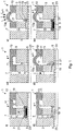
- the Figure 1 shows an actuator in six different states i to vi.
- the Figure 1i shows the actuator 1 in an idle state.
- the actuator 1 is designed as a microfluidic actuator which comprises a rigid volume body 3 which is arranged on a planar substrate 5.
- An actuator fluid supply 7, an actuator fluid supply connection 9 and an actuator chamber 11 are formed in the volume body 3 of the actuator 1.
- the wall of the actuator chamber 11 is formed in some areas by an elastomer membrane 13 which is attached to the volume body 3, for example by gluing or lamination.
- the actuator fluid supply 7 and the actuator fluid supply connection 9 are as microfluidic Channels formed.
- the actuator fluid supply 7 and / or the actuator fluid supply connection 9 have a diameter of less than 1 mm, preferably less than 100 ⁇ m and in particular a diameter of approximately 10 ⁇ m to approximately 50 ⁇ m.
- the volume of the actuator chamber 11 is accordingly in a range from approximately 0.01 mm 3 to approximately 2 mm 3 .
- the actuator fluid supply 7 is filled with an actuator fluid 15 and fluidly connected to an actuator fluid source (not shown) in order to be able to provide an overpressure in the actuator fluid supply 7.
- the actuator chamber 11 is filled with an actuator chamber fluid 17 which can be different from or identical to the actuator fluid 15 in the actuator fluid supply 7.
- the volume body 3 of the actuator 1 is mechanically rigid in such a way that the volume body 3 is essentially not mechanically deformed when there is an overpressure.
- the volume body 3 can for example be made of a polymer such as PVC, PE, PP, ABS, polycarbonate and the like.
- the elastomer membrane 13 is designed to be elastically resilient and deformable. In other words, the elastomer membrane 13 can be deformed by an overpressure applied in the actuator chamber 11.
- the elastomer membrane 13 Since the elastomer membrane 13 is resilient, the elastomer membrane 13 returns to its original shape or position when the overpressure of the actuator chamber fluid 17 is no longer present in the actuator chamber 11.
- the volume body 3 is more rigid than the elastomer membrane 13.
- the volume body 3 has a greater shear modulus and / or elasticity module than the elastomer membrane 13.
- a heating element 19 is arranged, which can be designed, for example, as an ohmic resistor or heating resistor 19.
- the heating element 19 can be designed as an SMD component, which can be electrically connected to a printed circuit board 5 as a preferred planar substrate 5.
- the circuit board 5 can then be used both as a mechanical carrier for the volume body 3 and as a Serve energy supply for the heating element 19.
- the actuator fluid supply connection 9 is filled with a sealing medium 21.
- the sealing medium 21 can also fill parts of the actuator fluid supply 7.
- the sealing medium 21 contacts the heating element 19 directly. It goes without saying, however, that the sealing medium and the heating element 19 can also be separated from one another by further elements, the heating element 19 making thermal contact with the sealing medium 21. In other words, the sealing medium 21 can be heated by means of the heating element 19.
- the actuator 1 further preferably comprises a cooling element 23, which can be designed, for example, as a Peltier element.
- the cooling element 23 contacts the sealing medium 21 only indirectly via the planar substrate 5. In other words, the thermal contact is established via the planar substrate 5.
- the sealing medium 21 can thus be cooled by means of the cooling element 23.
- the cooling can take place locally, the sealing medium 21 preferably being cooled or being coolable exclusively within the actuator fluid supply connection 9 or in the area of the actuator fluid supply connection 9.
- the actuator 1 is preferably operated at an ambient temperature of 20 ° C to about 24 ° C. Since the actuator 1 has no further thermally active components apart from the heating element 19 and the cooling element 23, the temperature corresponds within the actuator, in particular within the actuator fluid supply connection 9, the ambient temperature when the heating element 19 and the cooling element 23 are deactivated.
- the sealing medium 21 is preferably selected in such a way that it is in a solid state of aggregation at a temperature corresponding to the ambient temperature (that is to say approximately 20 ° C. to 24 ° C.).
- the heating element 19 is dimensioned such that the heating element 19 provides a heating power which is sufficient to heat the sealing medium 21 to a temperature above the melting point.
- An exemplary sealing medium 21 is paraffin which, depending on the molecular length of the alkanes contained therein, has a melting point of about 45 ° C. to about 80 ° C.
- the sealing medium 21 is expediently chemically resistant to the actuator fluid 15, in particular not detachable.
- the sealing medium 21 can consist of one or more non-polar substance (s), while the actuator fluid 15 consists of one or more polar substance (s).
- the sealing medium 21 water, for example, can serve as the actuator fluid 15.
- actuator fluid 15 and the sealing medium 21 can preferably be identical.
- actuator fluid 15 and sealing medium 21 can consist of a single liquid (for example water) which is liquid without cooling and which solidifies as a result of the cooling.
- the actuator 1 goes to in Fig. 1ii shown state, which is maintained as long as the heating element 19 is switched on.
- the sealing medium 21 is heated to a temperature above the melting temperature, for example above 45 ° C. or approximately above 80 ° C., so that the sealing medium 21 changes into the liquid state of aggregation.
- the actuator chamber 11 is no longer separated from the actuator fluid supply 7 in a pressure-tight manner by means of the closure medium 21.
- the actuator fluid 15 and the sealing medium 21 are displaced in the direction of the actuator chamber 11.
- an overpressure in the actuator fluid supply 7 By applying an overpressure in the actuator fluid supply 7 (see Fig. 1iii ) An overpressure is also applied in the actuator chamber 11, which is now fluidly connected to the actuator fluid supply 7 via the actuator fluid supply connection 9. Due to the overpressure in the actuator chamber 11, the elastomer membrane 13 is deformed or at least partially displaced along an actuation direction A.
- the pressure in the actuator fluid supply 7 can be applied, for example, by means of an actuator fluid source (not shown).
- the actuator fluid 15 contained in the actuator fluid supply 7 can also be subjected to the overpressure by means of another fluid.
- an incompressible actuator fluid 15 can be filled into the actuator fluid supply 7, such as a liquid, for example water or aliphatic hydrocarbons.
- actuator fluid 15 can be pneumatically subjected to an overpressure.
- a compressed air source (not shown) can be fluidically connected to the actuator fluid supply 7, see above that the actuator fluid 15 contained in the actuator fluid supply 7 is subjected to an overpressure by means of the compressed air.
- the overpressure required for actuating the elastomer membrane 13 as a preferred embodiment of an actuator element can be about 1 bar to about 4 bar, more preferably the overpressure can be about 2 bar to about 3 bar.
- the heating element 19 is switched off (see FIG Fig. 1iv ), so that the sealing medium 21 is not heated any further.
- the sealing medium 21 can be cooled by means of the cooling element 23. If the sealing medium 21 has cooled below the melting point, the sealing medium 21 is again in a solid state of aggregation.
- the actuator fluid supply connection 9 is again closed in a pressure-tight manner. After the sealing medium 21 has solidified or the actuator fluid supply connection 9 has been closed, further cooling by means of the cooling element 23 is no longer necessary.
- the cooling element 23 can be operated continuously, the heating element 19 being switched on only to melt the sealing medium 21.
- This alternative mode of operation is expediently carried out in the event that the sealing medium 21 has a melting point which is below the operating temperature of the actuator 1, for example when using water as the sealing medium 21.
- Activating the heating element 19 leads to a melting of the sealing medium 21 in the actuator fluid supply connection 9, so that the overpressure present in the actuator chamber 11 can escape by shifting the sealing medium 21 to a position further away from the actuator chamber 11 if there is no in the actuator fluid supply 7 Overpressure is present (see Fig. 1v ).
- the pressure in the actuator fluid supply 7 can correspond to the ambient pressure of the actuator 1, which also acts on the outside 13a of the elastomer membrane 13 against the actuation direction A. The restoring force of the resilient, elastically deformable elastomer membrane 13 then resets the elastomer membrane and displaces the closure medium 21, as in FIG Figure 1vi shown.
- the heating element 19 can be deactivated so that the sealing medium 21 solidifies again and the actuator fluid supply connection 9 closes pressure-tight, so that the actuator 1 is in the rest position, as in FIG Figure 1i shown returns.
- the actuator 1 as in the Figure 1 shown, has exactly two stable states, namely the state of rest (see Fig. 1i ) and the actuation state (see Fig. 1iv ), the actuator 1 can also be referred to as a bistable actuator 1.
- the Indian Figure 1 The actuator 1 shown preferably has an actuator fluid supply connection 9, which has a diameter or a gap width of approximately 10 ⁇ m to approximately 1 mm, whereby only a small volume of sealing medium 21 is required to seal the actuator fluid supply connection 9.
- the actuator 1 advantageously has improved actuator dynamics, since the time to melt the small volume of sealing medium 21 is correspondingly short.
- the switching times of the actuator 1 from the idle state to the actuation state can therefore be in the range from about 0.1 sec to about 1 sec.
- the heating zone for the heating element 19 remains limited to the area of the actuator fluid supply connection 9.
- the heating element 19 can form a wall of the actuator fluid supply connection 9.
- the contact surface of the heating element 19 with the sealing medium 21 can be so favorable in relation to the volume of the sealing medium 21 that the sealing medium 21 melts in the entire volume of the actuator fluid supply connections 9 can preferably take place in a time less than 1 second.
- the heating element 19 can preferably be designed as an SMD component (surface mounted device), as a result of which the heating element 19 can be attached in a simple manner to a circuit board 5 as a preferred planar substrate 5 and can be electrically contacted.
- the actuator 1 also advantageously enables spatial decoupling and thus an effective thermal separation between the (thermally modulated) actuator fluid supply connection 9 and the actuator chamber 11 or the actuator element 13, which is preferably designed as an elastomer membrane 13, that is, the location at which the Actuator element 13 is displaced along the actuation direction A (at the location at which an actuator stroke occurs). Since the actuator fluid 15 is preferably an incompressible liquid, the actuator stroke can be hydraulically transmitted almost indefinitely. In other words, the fluidic connection between the actuator chamber 11 and the actuator fluid supply connection 9 can be longer than a few millimeters, in particular larger than 1 cm, preferably larger than 5 cm, so that the actuator can be designed in a variable manner.
- the actuator comprises, in addition to the heating element, a heat sink or a cooling element 23, which can for example be designed in the form of a heat pipe or a Peltier element.
- the cooling element 23 can preferably be permanently in operation. This is particularly advantageous because it is technically easier to generate heat locally than to dissipate heat locally.
- the heating element 19 can be switched on and off in a time-controlled manner in order to overcompensate for the cooling element 23.
- a common cooling element 23 can be provided in an arrangement of several actuators 1, which serves as a common heat sink for a plurality of heating elements 19.
- the in Figure 1 shown actuator 1 structurally simple. It preferably comprises a solid volume body 3, a planar substrate 5, with heating elements 19 arranged or fastened thereon and electrically contacted, and an elastomer membrane 13 applied to volume body 3.
- a solid volume body 3 preferably comprises a solid volume body 3, a planar substrate 5, with heating elements 19 arranged or fastened thereon and electrically contacted, and an elastomer membrane 13 applied to volume body 3.
- the connections between the volume body 3 and the elastomer membrane 13 or the volume body 3 and the planar substrate 5 are flat or surface-effective.
- the elastomer membrane 13 can be connected to the volume body 3 by gluing or lamination.
- the solid 3 can be connected to the planar substrate 5 by gluing or lamination.
- Actuator 1 shown is bistable in the classic sense: The idle state of the actuator, in which the actuator element is in a rest position, as well as the actuation state, in which the actuator element is deflected along the actuation direction A and is in an actuation position, are determined via the phase transition of the Sealing medium stabilized.
- the solid state of aggregation of the sealing medium 21 means that the state of the actuator 1 no longer changes without the actuator 1 being supplied with energy which, for example by means of the heating element 19, converts the sealing medium 21 into the liquid state of aggregation.
- the actuator fluid 15 must always be liquid at the temperatures which occur in the actuator fluid supply 7 during operational use of the actuator 1.
- paraffins which typically have a melting point greater than 40 ° C, are not suitable as actuator fluid 15.
- Incompressible liquids are preferably used as actuator fluid 15, for example water or aliphatic hydrocarbons whose melting points are below the temperature of the actuator 1 during normal use (for example around 0 ° C).
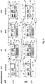
- the Figure 2 shows sectional views through a further preferred embodiment of a bistable actuator 1 in eight different states i to viii.
- the structure of the actuator 1 in Figure 2 corresponds in many elements to the structure of the in Figure 1 shown actuator. The identical components are therefore provided with identical reference symbols.
- the actuator 1 comprises a solid 3, which consists of two layers 3a and 3b, which are connected or glued to one another, for example by lamination.
- An actuator fluid supply 7 and an actuator fluid supply connection 9 are formed in the volume body 3 within a first layer 3 a of the volume body 3.
- the second layer 3b of the volume body 3 at least partially forms an actuator chamber 11 which is fluidically connected to the actuator fluid supply connection 9.
- An elastomer membrane 13 is attached to the second layer 3b of the volume body 3, the elastomer membrane 13 forming at least one wall of the actuator chamber 11.
- a reservoir fluid supply 25 and a reservoir fluid supply connection 27, which are not fluidly connected to the actuator fluid supply 7 or are separated from it, are formed in the first layer 3a of the volume body 3.
- a second elastomer membrane 29 is arranged or fastened on the first layer 3 a of the volume body 3, which at least regionally forms a wall of the actuator fluid supply connection 9 and the reservoir fluid supply connection 27.
- the second elastomer membrane 29 is designed to be elastically resilient in the area that forms the wall of the actuator fluid supply connection 9, so that the second elastomer membrane 29 functions as a closure element 29a in this area.
- the second elastomer membrane 29 is designed to be deformable in the area which forms the wall of the reservoir fluid supply connection 27, so that this area of the second elastomer membrane 29 can serve as a pressure transmission element 29b.
- the pressure transmission element 29b is deformable in that an overpressure is applied in the reservoir fluid supply connection 27 by means of the reservoir fluid supply 25 the pressure transmission element 29b is applied, which is thereby deformed.
- a second volume body 31 is arranged or fastened to the second elastomer membrane 29.
- a sealing medium reservoir 33 which contains a sealing medium 21, is formed in the second volume body 31.
- the sealing medium reservoir 33 is fluidically connected to the sealing element 29a and the pressure transmission element 29b. This can preferably be realized in that the closure element 29a and / or the pressure transmission element 29b at least regionally form or form the wall of the closure medium reservoir 33.
- a heating element 19 can preferably be arranged in the sealing medium reservoir 33, which is designed to heat the sealing medium 21 within the sealing medium reservoir 33 in order to convert it from a solid state to a liquid state.
- a preferred sealing medium 21 is paraffin, as already mentioned in relation to FIG Figure 1 is described.
- a planar substrate 5 is arranged or fastened, the planar substrate 5 in a preferred embodiment being designed as a printed circuit board 5 which carries the heating element 19 and makes electrical contact with it.
- the embodiment of the actuator 1 shown essentially corresponds to the mode of operation of the in Figure 1 shown actuator, the locking device of the in Figure 2
- the actuator 1 shown comprises a bistable actuator filled with the sealing medium 21.
- the actuator element 13 which is designed as an elastically and resiliently deformable elastomer membrane 13, is in a rest position.
- the actuator fluid supply connection 9 is closed in a fluid-tight and pressure-tight manner by a deformed region of the second elastomer membrane 29, so that the actuator chamber 11 is fluidically separated from the actuator fluid supply 7.
- the deformed one The area of the second elastomer membrane therefore acts as a closure element 29a.
- the closure element 29a is preferably held in its position by a solidified closure medium 21 which is arranged in the closure medium reservoir 33. Whether there is an overpressure in the reservoir fluid supply 25 is therefore not relevant for the position of the closure element 29a.
- the actuator 1 is thus in a stable state.
- the sealing medium 21 is melted or liquefied in the sealing medium reservoir 33 so that the resilient sealing element 29a can return to its original shape or position if there is no overpressure in the reservoir fluid supply 25.
- This causes the actuator to go into the Figure 2ii state shown, in which the actuator chamber 11 is fluidically connected to the actuator fluid supply 7 via the actuator fluid supply connection 9.
- the heating element 19 can now be deactivated again, as shown in FIG Figure 2iv is shown in that the heating element 19 is no longer shown filled.
- the sealing medium 21 By activating the heating element 19, the sealing medium 21 can be melted or kept liquid in the sealing medium reservoir 33, so that by applying an overpressure in the reservoir fluid supply 25, which with the reservoir fluid supply connection 27 can exert the overpressure on the sealing medium reservoir 33, the liquid sealing medium 21 are subjected to an overpressure in such a way that the elastic deformable closure element 29a is deformed in such a way as to close the actuator fluid supply connection 9.
- This state is in the Figure 2vi shown.
- the sealing medium 21 solidifies in the sealing medium reservoir 33, so that the sealing element 29a is stable in the closed position, as in FIG Figure 2viii shown is held.
- This state which can be referred to as the actuation state of the actuator 1, is stable without any further energy supply.
- the heating element 19 can be activated, while at the same time no excess pressure is applied in the reservoir fluid supply 25, as shown in FIG Figure 2vii is shown.
- the closure element 29a goes back into an open position in which the actuator fluid supply connection 9 between the actuator chamber 11 and the actuator fluid supply 7 is open.
- the heating element 19 can be deactivated in this phase, as shown in FIG Figure 2v is shown.
- the heating element 19 can in turn be activated in order to keep the sealing medium 21 liquid or to melt it in the sealing medium reservoir 33, an overpressure then being applied in the reservoir fluid supply 25 to, as described above to transfer the closure element 29a into a closed position in which the actuator fluid supply connection 9 is closed in a fluid-tight and pressure-tight manner.
- This state is in Figure 2iii shown.
- the closure element 29a is held stably in the closed position, so that the actuator 1 in the in Figure 2i the idle state shown.
- the actuators described are bistable and binary.
- the actuator element 13 can be in two different states, namely in the rest position and in the actuation position.
- the actuator 1 can be brought into a stable state in which the actuator element is held in the rest position or in the actuation position without any further energy supply.
- the actuators described can advantageously be so highly integrated.
- it is structurally simple to introduce several such actuators into a solid volume body, for example a polymer component. This can advantageously take place by means of simple and inexpensive manufacturing processes, for example by means of injection molding technology.
- a printed circuit board can be arranged or fastened on one side of the polymer component or the volume body 3.
- an individually addressable heating resistor 19 can be assigned to each actuator 1.
- the actuator chambers 11, the actuator fluid supply connection 9 and at least partially the actuator fluid supply 7 can then be filled with a fluid, for example water.
- this arrangement can be frozen in this state, for example in a freezer, before a flat and structured elastomer membrane 13 is applied or fastened as a preferred actuator element 13, the elastomer membrane 13 closing the actuator chambers 11.
- actuators 1 can be structurally highly integrated, for example around 500 actuators in the immediate vicinity. These can preferably be controlled via a printed circuit board with a correspondingly approximately one hundred individually addressable heating elements 19, with each individual actuator being assigned an individually addressable heating element 19.
- a common heat sink can preferably be attached or arranged on the circuit board, for example in the form of an electrically switchable Peltier element. If the individual actuator fluid supplies are now operated with an actuator fluid via a common fluid source or a common fluid reservoir, a simple, scalable functional principle is made possible.
- the common fluid reservoir is periodically loaded with an overpressure (for example 3 bar), held for a few seconds and relaxed again to ambient pressure.
- the individual heating elements 19 can now be switched on and off synchronously with this pressurization and relief.
- this parallel pressurization in connection with the use of a phase transition or physical state transition in an actuator fluid supply connection, which can be designed as a thin gap or thin channel, the result is that a simple, robust binary and stable, highly integrable and almost unlimitedly scalable actuator arrangement can be produced can.
- the actuator has high dynamics because, due to the small volume in the actuator fluid supply connection 9, the volume of sealing medium 21 which is to be melted or solidified is very small, for example less than 1 mm 3 and in particular less than 0.1 mm 3 .
- an almost point-shaped heating source in the form of a heating element 19 can advantageously be used, in order to carry out the melting of the sealing medium 21. More preferably, such a heating element can be designed inexpensively and simply as an SMD resistor, which can be contacted to the circuit board in a simple manner.
- any actuator stroke of the actuator element 13 can take place, since the strength of the actuator stroke is independent of the amount of the sealing medium. Rather, an actuator fluid can be provided with any pressure and any volume in order to provide any actuator stroke of the actuator element 13 or any actuation force of the actuator element 13. It is also advantageously possible to operate a plurality of actuator elements 13 in parallel with a single external pressure source which provides an actuator fluid 15.
- an actuator arrangement can be set up and manufactured in a simple manner, since the individual components can be manufactured separately and can be connected to one another over a large area by gluing or lamination.
- the filling of the sealing medium is thereby possible in a simple manner. This can be arranged as a solid or in liquid form in the associated recess of the corresponding component of the actuator arrangement during manufacture.
- the heating elements 19 can be spaced as desired from the actuator element 13, in particular the sealing medium 21 not making contact with the current element. This makes it structurally possible to provide a simple and more efficient heat dissipation for the sealing medium 21, as a result of which it can solidify in a shorter time.
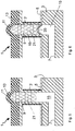
- the Figures 3i to 3vi show another preferred embodiment of the actuator in six different states i to vi.
- the Figure 3i shows the actuator 1 in an idle state.
- the actuator 1 is designed as a microfluidic actuator which comprises an essentially rigid volume body 3 on which a planar substrate 5 is preferably arranged.
- the solid 3 comprises a protuberance 3 ', which extends through an opening 5 'of the planar substrate.
- An actuator fluid supply 7, an actuator fluid supply connection 9 and an actuator chamber 11 are formed in the volume body 3 of the actuator 1.
- the actuator fluid supply connection 9 and the actuator chamber 11 can be arranged together within a cavity which is arranged in the protuberance 3 '.
- the actuator fluid supply connection 9 and the actuator chamber 11 can form a common cylindrical cavity.
- the bulge 3 ′ of the volume body 3 can be essentially tubular, at least in some areas, the actuator fluid supply connection 9 and / or the actuator chamber 11 being / are arranged in the tubular area.
- the wall of the actuator chamber 11 is formed in some areas by an elastomer membrane 13 which is attached to the volume body 3 or its protuberance 3 ', for example by gluing or lamination.
- the elastomer membrane can have a recess which at least partially forms the actuator chamber 11.
- the actuator fluid supply 7 and / or the actuator fluid supply connection 9 and / or the actuator chamber 11 is / are designed as microfluidic channels.
- the actuator fluid supply 7 and / or the actuator fluid supply connection 9 and / or the actuator chamber 11 have a diameter of less than 1 mm, preferably less than 100 ⁇ m and in particular a diameter of approximately 10 ⁇ m to approximately 50 ⁇ m.
- the volume of the actuator chamber 11 is accordingly in a range from approximately 0.01 mm 3 to approximately 2 mm 3 .
- the actuator fluid supply 7 is filled with an actuator fluid 15 and fluidly connected to an actuator fluid source (not shown) in order to be able to provide an overpressure in the actuator fluid supply 7.
- the actuator chamber 11 is filled with an actuator chamber fluid 17 which can be different from or identical to the actuator fluid 15 in the actuator fluid supply 7.
- the volume body 3 or the protuberance 3 'of the actuator 1 is so mechanically rigid that the volume body 3 or the protuberance 3' is essentially not mechanically deformed when an excess pressure is applied.
- the volume body 3 can for example be made of a polymer such as PVC, PE, PP, ABS, polycarbonate and the like.
- the elastomer membrane 13 is designed to be elastically resilient and deformable. In other words, the elastomer membrane 13 can be deformed by an overpressure applied in the actuator chamber 11. Since the elastomer membrane 13 is resilient, the elastomer membrane 13 returns to its original shape or position when the overpressure of the actuator chamber fluid 17 is no longer present in the actuator chamber 11.
- the volume body 3 is more rigid than the elastomer membrane 13.
- the volume body 3 has a greater shear modulus and / or elasticity module than the elastomer membrane 13.
- a heating element 19 is arranged, which can be designed, for example, as an ohmic resistor or heating resistor 19.
- the heating element 19 can be designed as a heating wire which is wound on the outside around the wall of the actuator fluid supply connection 9 or around the wall formed by the protuberance 3 ', in particular in a spiral shape.
- the heating element 19 can be electrically connected to a printed circuit board 5 as a preferred planar substrate 5.
- the printed circuit board 5 can then advantageously serve both as a mechanical carrier for the volume body 3 and as an energy supply for the heating element 19.
- the actuator fluid supply connection 9 is filled with a sealing medium 21.
- the sealing medium 21 can also fill parts of the actuator fluid supply 7.
- the preferred embodiment of the actuator 1 shown here contacts the sealing medium 21 indirectly via the wall of the actuator fluid supply connection 9 or the protuberance 3 'with the heating element 19.
- the sealing medium 21 and the heating element 19 are also connected to each other by additional means Elements can be separated, with the heating element 19 thermally contacting the sealing medium 21, or that the heating element 19 is arranged within the actuator fluid supply connection 9 so that the heating element 19 and the sealing medium contact one another directly (see Figure 4 ).
- the sealing medium 21 can be heated by means of the heating element 19.
- the actuator 1 further preferably comprises a cooling element 23, which can be designed, for example, as a Peltier element.
- the cooling element 23 can make direct or indirect contact with the heating element 19 and / or the planar substrate 5.
- the cooling element 23 can be designed as a fluid channel through which a fluid that is relatively cold compared to the actuator fluid 7 or the sealing medium 21 is guided to the heating element 19 or to the actuator fluid supply connection 9 in order to cool the sealing medium 21.
- the actuator 1 is preferably operated at an ambient temperature of 20 ° C to about 24 ° C. Since the actuator 1 has no other thermally active components apart from the heating element 19 and the cooling element 23, the temperature within the actuator, in particular within the actuator fluid supply connection 9, corresponds to the ambient temperature when the heating element 19 and the cooling element 23 are deactivated.
- the sealing medium 21 is preferably selected in such a way that it is in a solid state of aggregation at a temperature corresponding to the ambient temperature (that is to say approximately 20 ° C. to 24 ° C.). Furthermore, the heating element 19 is dimensioned such that the heating element 19 provides a heating power that is sufficient to raise the sealing medium 21 to a temperature above the To heat the melting point.
- An exemplary sealing medium 21 is paraffin which, depending on the molecular length of the alkanes contained therein, has a melting point of about 45 ° C. to about 80 ° C.
- the actuator 1 goes to in Fig. 3ii shown state, which is maintained as long as the heating element 19 is switched on.
- the sealing medium 21 is heated to a temperature above the melting temperature, for example above 45 ° C. or approximately above 80 ° C., so that the sealing medium 21 changes into the liquid state of aggregation.
- the actuator chamber 11 is no longer separated from the actuator fluid supply 7 in a pressure-tight manner by means of the closure medium 21.
- the sealing medium 21 preferably has the same density as the surrounding actuator fluid 7 or the actuator chamber fluid 17, in order to prevent the sealing medium 21 from sinking down due to gravity or rising into the actuator chamber 11.
- an overpressure is also applied in the actuator chamber 11, which is now fluidly connected to the actuator fluid supply 7 via the actuator fluid supply connection 9. Due to the overpressure in the actuator chamber 11, the elastomer membrane 13 is deformed or at least partially along a Actuation direction A shifted.
- the pressure in the actuator fluid supply 7 can be applied, for example, by means of an actuator fluid source (not shown).
- the actuator fluid 5 contained in the actuator fluid supply 7 can also be subjected to the overpressure by means of another fluid.
- an incompressible actuator fluid 15 can be filled into the actuator fluid supply 7, such as a liquid, for example water or aliphatic hydrocarbons.
- Essentially all liquids can be used as actuator fluid 15 whose melting points are just below the working range (for example about 0 ° C.) of the actuator.
- Incompressible liquids are advantageously volume-invariant, so that the overpressure acting in the actuator fluid supply 7 does not cause any change in the actuator fluid volume, which advantageously avoids loss of effectiveness due to the compression of the actuator fluid.
- the actuator fluid 15 in the actuator fluid supply 7 can be pneumatically subjected to an overpressure.
- a compressed air source (not shown) can be fluidically connected to the actuator fluid supply 7, so that the actuator fluid 15 contained in the actuator fluid supply 7 is subjected to an overpressure by means of the compressed air.
- the overpressure required for actuating the elastomer membrane 13 as a preferred embodiment of an actuator element can be approximately 1 bar to approximately 4 bar, more preferably the excess pressure can be approximately 2 bar to approximately 3 bar.
- the heating element 19 is switched off, as in FIG Figure 3iii shown so that the sealing medium 21 is not heated any further.
- the sealing medium 21 can be cooled by means of the cooling element 23. If the sealing medium 21 has cooled below the melting point, the sealing medium 21 is again in a solid state of aggregation.
- the actuator fluid supply connection 9 is again closed in a pressure-tight manner. After the sealing medium 21 has solidified or the actuator fluid supply connection 9 has been closed, further cooling by means of the cooling element 23 is no longer necessary.
- Actuator chamber 11 held overpressure of the actuator chamber fluid 17 remains displaced or deformed in the actuation position. Since the overpressure of the actuator chamber fluid 17 in the actuator chamber 11 is independent of the pressure conditions in the actuator fluid feed 7 due to the pressure-tight closure of the actuator fluid supply connection 9 by means of the closure medium 21, the overpressure applied to the actuator fluid supply 7 can be released again.
- the actuation state can therefore also be referred to as the second stable state.
- Activation of the heating element 19 leads to a melting of the sealing medium 21 in the actuator fluid supply connection 9, so that the overpressure present in the actuator chamber 11 can escape by shifting the sealing medium 21 to a position further away from the actuator chamber 11 if there is no excess pressure in the actuator fluid supply 7.
- the pressure in the actuator fluid supply 7 can correspond to the ambient pressure of the actuator 1, which also acts on the outside 13a of the elastomer membrane 13 against the actuation direction A.
- the restoring force of the resilient, elastically deformable elastomer membrane 13 then resets the elastomer membrane and displaces the closure medium 21, as in FIG Figure 3vi shown.
- the heating element 19 can be deactivated so that the sealing medium 21 solidifies again and the actuator fluid supply connection 9 closes pressure-tight, so that the actuator 1 is in the rest position, as in FIG Figure 3i shown returns. Since the actuator 1, as in the Figure 3 shown, has exactly two stable states, namely the idle state and the actuation state, the actuator 1 can also be referred to as a bistable actuator 1.
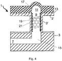
- Figure 4 shows a further preferred embodiment of the actuator.
- This embodiment corresponds essentially to that in FIGS Figures 3i to 3vi embodiment shown, wherein identical components are marked with identical reference numerals and the description of the Figures 3i to 3vi also for those in the Figure 4 embodiment shown applies.
- the ones in the Figure 4 The embodiment shown of the actuator 1 has a heating element 19 which is arranged on the inner wall of the actuator fluid supply connection 9 or the protuberance 3 'and which makes direct contact with the sealing medium 21.
- the heating element 19 can be designed as a spirally wound heating wire.
- Figure 5 shows a further preferred embodiment of the actuator 1.
- This embodiment corresponds essentially to that in FIG Figures 3i to 3vi embodiment shown, wherein identical components are marked with identical reference numerals and the description of the Figures 3i to 3vi also for those in the Figure 5 embodiment shown applies.
- the ones in the Figure 5 The embodiment shown of the actuator 1 has sealing medium 21 which cannot be physically mixed with the actuator fluid 15 or is chemically soluble. In other words, a stable phase boundary is formed between the actuator fluid 15 and the sealing medium 21.
- the sealing medium 21 can contain a paraffin, while the actuator fluid 15 comprises a polar solvent, for example water.
- the sealing medium can differ from that in the Figures 1 to 4
- the embodiments shown also reach the actuator chamber 11 or it can also take on the role of the actuator chamber fluid.
- Figure 6 shows a further preferred embodiment of the actuator 1.
- This embodiment corresponds essentially to that in FIG Figures 3i to 3vi embodiment shown, wherein identical components are marked with identical reference numerals and the description of the Figures 3i to 3vi also for those in the Figure 6 embodiment shown applies.
- the ones in the Figure 6 The embodiment shown of the actuator 1 has a closure medium 21 which is spatially separated from the actuator fluid 15 by an elastic membrane 35.
- the elastic membrane forms a fluid-tight barrier between the actuator fluid supply 7 and the actuator fluid supply connection 9, so that the actuator fluid 15 and the sealing medium 21 cannot contact and mix directly.
- due to the elasticity of the membrane 35 a pressure prevailing in the actuator fluid 15 can be transmitted to the sealing medium.
- actuator fluids and sealing media can be used which are miscible or releasable with one another in direct contact.
Landscapes
- Engineering & Computer Science (AREA)
- General Engineering & Computer Science (AREA)
- Mechanical Engineering (AREA)
- Chemical & Material Sciences (AREA)
- Physics & Mathematics (AREA)
- Dispersion Chemistry (AREA)
- Combustion & Propulsion (AREA)
- Fluid Mechanics (AREA)
- Health & Medical Sciences (AREA)
- Audiology, Speech & Language Pathology (AREA)
- General Health & Medical Sciences (AREA)
- Business, Economics & Management (AREA)
- Educational Administration (AREA)
- Educational Technology (AREA)
- General Physics & Mathematics (AREA)
- Theoretical Computer Science (AREA)
- Micromachines (AREA)
- Actuator (AREA)
- Fluid-Pressure Circuits (AREA)
Claims (11)
- Méthode d'actionnement bistable d'un actionneur (1) comprenant les étapes suivantes:- l'application d'une surpression dans une amenée de fluide d'actionneur (7), laquelle est reliée à une chambre d'actionneur (11) par connexion fluidique au moyen d'un raccord d'amenée de fluide d'actionneur (9), dans laquelle une surpression de travail est générée dans la chambre d'actionneur (11), moyennant quoi un élément d'actionneur (13) relié à la chambre d'actionneur (11) par connexion fluidique est transféré d'une position de repos vers une position d'actionnement ;- la fermeture étanche à la pression du raccord d'amenée de fluide d'actionneur (9), de sorte que la surpression de travail est maintenue dans la chambre d'actionneur (11) et que l'élément d'actionneur (13) reste dans la position d'actionnement,caractérisée en ce que- la fermeture étanche à la pression s'effectue au moyen d'un milieu de fermeture liquéfiable (21), lequel est disposé à l'état liquide dans le raccord d'amenée de fluide d'actionneur (9) et se solidifie dans le raccord d'amenée de fluide d'actionneur (9), dans laquelle la chambre d'actionneur (11) est séparée de l'amenée de fluide d'actionneur (7) par connexion fluidique au moyen du milieu de fermeture solidifié (21).
- Méthode selon la revendication 1, comprenant encore l'étape suivante :- la liquéfaction du milieu de fermeture (21), lequel est disposé dans le raccord d'amenée de fluide d'actionneur (9) entre la chambre d'actionneur (11) et l'amenée de fluide d'actionneur (7) et lequel sépare la chambre d'actionneur (11) de l'amenée de fluide d'actionneur (7) par connexion fluidique, dans laquelle le milieu de fermeture liquéfié (21) est déplacé au moins en partie en direction de la chambre d'actionneur (11) lors de l'application de la surpression.
- Méthode selon l'une des revendications précédentes, comprenant encore l'étape suivante :- le relâchement de la surpression ou l'application d'une dépression dans l'amenée de fluide d'actionneur (7).
- Méthode selon la revendication 3, comprenant encore l'étape suivante :- la liquéfaction du milieu de fermeture (21) dans le raccord d'amenée de fluide d'actionneur (9), dans laquelle la surpression de travail baisse dans la chambre d'actionneur (11) et l'élément d'actionneur (13) revient de la position d'actionnement dans la position de repos.
- Méthode d'actionnement bistable d'un actionneur (1) comprenant les étapes suivantes :- l'application d'une surpression dans une amenée de fluide d'actionneur (7), laquelle est reliée à une chambre d'actionneur (11) par connexion fluidique au moyen d'un raccord d'amenée de fluide d'actionneur (9), dans laquelle une surpression de travail est générée dans la chambre d'actionneur (11), moyennant quoi un élément d'actionneur (13) relié à la chambre d'actionneur (11) par connexion fluidique est transféré d'une position de repos vers une position d'actionnement ;- la fermeture étanche à la pression du raccord d'amenée de fluide d'actionneur (9), de sorte que la surpression de travail est maintenue dans la chambre d'actionneur (11) et que l'élément d'actionneur (13) reste dans la position d'actionnement,caractérisée en ce que
la fermeture étanche à la pression comprend :- la liquéfaction d'un milieu de fermeture liquéfiable (21) dans un réservoir de milieu de fermeture (33) ;- la mise en surpression du réservoir de milieu de fermeture (33), dans laquelle un élément de fermeture (29a) est transféré d'une position ouverte vers une position fermée, de sorte que la chambre d'actionneur (11) est séparée de l'amenée de fluide d'actionneur (7) par connexion fluidique au moyen de l'élément de fermeture (29a) ; et- la solidification du milieu de fermeture liquéfiable (21), de sorte que l'élément de fermeture (29a) reste dans la position fermée. - Actionneur bistable (1) comprenant :- une amenée de fluide d'actionneur (7), laquelle permet de fournir un fluide d'actionneur (15) et est reliée à une chambre d'actionneur (11) par connexion fluidique au moyen d'un raccord d'amenée de fluide d'actionneur (9) ;- au moins un élément d'actionneur (13) relié à la chambre d'actionneur (11) par connexion fluidique, lequel peut être transféré d'une position de repos vers une position d'actionnement moyennant l'application d'une surpression dans la chambre d'actionneur (11) ;- un dispositif de fermeture (19, 21 ; 21, 29a, 33), lequel permet de fermer le raccord d'amenée de fluide d'actionneur (9) de manière étanche à la pression,caractérisé en ce que
le dispositif de fermeture (19, 21) comprend un milieu de fermeture liquéfiable (21) et un élément de chauffage (19), lequel permet de liquéfier le milieu de fermeture (21), dans lequel :le milieu de fermeture liquéfiable (21) est disposé dans le raccord d'amenée de fluide d'actionneur (9) ; oule milieu de fermeture liquéfiable (21) est disposé dans un réservoir de milieu de fermeture (33) de l'actionneur (1), dans lequel le réservoir de milieu de fermeture (33) est relié à un élément de fermeture (29a) par connexion fluidique, lequel peut être transféré d'une position ouverte vers une position fermée moyennant l'application d'une surpression dans le réservoir de milieu de fermeture (33), de sorte que la chambre d'actionneur (11) peut être séparée de l'amenée de fluide d'actionneur (7) par connexion fluidique moyennant l'élément de fermeture (29a). - Actionneur (1) selon la revendication 6, dans lequel le milieu de fermeture liquéfiable (21) est disposé dans le raccord d'amenée de fluide d'actionneur (9), dans lequel le milieu de fermeture (21) n'est pas miscible au fluide d'actionneur (15) ou dans lequel le milieu de fermeture (21) est séparé du fluide d'actionneur (15) par connexion fluidique moyennant une membrane élastique (35).
- Actionneur (1) selon la revendication 6 ou 7, dans lequel l'élément de chauffage (19) est en contact direct ou indirect avec le milieu de fermeture (19).
- Actionneur (1) selon l'une des revendications 6 à 8, dans lequel le milieu de fermeture (21) est disposé dans le réservoir de milieu de fermeture (33) et l'actionneur (1) présente une amenée de fluide de réservoir (25), laquelle est reliée au réservoir de milieu de fermeture (33) par connexion fluidique au moyen d'un raccord d'amenée de fluide de réservoir (27).
- Ensemble d'actionneurs avec au moins deux actionneurs (1) selon l'une des revendications 6 à 9, dans lequel les amenées de fluide (7) des actionneurs (1) et / ou les amenées de fluide de réservoir (25) des actionneurs (1) sont reliées les unes aux autres par connexion fluidique.
- Utilisation d'un ensemble d'actionneurs selon la revendication 10 servant de dispositif d'affichage haptique, dans laquelle des caractères tactiles peuvent être représentés au moyen des éléments d'actionneur (13) de l'ensemble d'actionneurs.
Applications Claiming Priority (2)
| Application Number | Priority Date | Filing Date | Title |
|---|---|---|---|
| DE201210005992 DE102012005992B3 (de) | 2012-03-23 | 2012-03-23 | Bistabiler Aktor, Aktoranordnung, Verfahren zum Aktuieren und Verwendung |
| PCT/EP2013/000294 WO2013139418A1 (fr) | 2012-03-23 | 2013-01-31 | Actionneur bistable, ensemble d'actionneurs, procédé servant à l'actionnement et utilisation associée |
Publications (2)
| Publication Number | Publication Date |
|---|---|
| EP2828537A1 EP2828537A1 (fr) | 2015-01-28 |
| EP2828537B1 true EP2828537B1 (fr) | 2020-12-30 |
Family
ID=47747547
Family Applications (1)
| Application Number | Title | Priority Date | Filing Date |
|---|---|---|---|
| EP13705390.6A Active EP2828537B1 (fr) | 2012-03-23 | 2013-01-31 | Actionneur bistable, ensemble d'actionneurs, méthode d'actionnement et utilisation |
Country Status (4)
| Country | Link |
|---|---|
| US (1) | US9689408B2 (fr) |
| EP (1) | EP2828537B1 (fr) |
| DE (1) | DE102012005992B3 (fr) |
| WO (1) | WO2013139418A1 (fr) |
Families Citing this family (5)
| Publication number | Priority date | Publication date | Assignee | Title |
|---|---|---|---|---|
| KR20160047156A (ko) * | 2014-10-22 | 2016-05-02 | 현대자동차주식회사 | 변속 인지 장치 및 방법 |
| DE102016213654A1 (de) * | 2016-07-26 | 2018-02-01 | Siemens Aktiengesellschaft | Aktorvorrichtung und Verfahren zum Betrieb einer Aktorvorrichtung |
| CN109555749B (zh) * | 2019-01-03 | 2023-09-12 | 杨斌堂 | 多管自给装置 |
| EP4068249B1 (fr) | 2021-03-31 | 2024-10-09 | Glassomer GmbH | Dispositif et procédé de commutation d'un fluide dans un canal de fluide, utilisation du dispositif et affichage tactile |
| WO2026024474A1 (fr) * | 2024-07-23 | 2026-01-29 | Artondale Enterprises Llc | Actionneur hydraulique |
Family Cites Families (14)
| Publication number | Priority date | Publication date | Assignee | Title |
|---|---|---|---|---|
| DE4119955C2 (de) * | 1991-06-18 | 2000-05-31 | Danfoss As | Miniatur-Betätigungselement |
| JP2001502247A (ja) * | 1996-02-10 | 2001-02-20 | フラウンホーファー―ゲゼルシャフト、ツール、フェルデルング、デァ、アンゲヴァンテン、フォルシュング、アインゲトラーゲネル、フェライン | 膜連結による双安定マイクロアクチュエータ |
| US6354839B1 (en) * | 1998-10-10 | 2002-03-12 | Orbital Research, Inc. | Refreshable braille display system |
| US6575188B2 (en) | 2001-07-26 | 2003-06-10 | Handylab, Inc. | Methods and systems for fluid control in microfluidic devices |
| DE10310072B4 (de) * | 2002-03-08 | 2005-07-14 | Erhard Prof. Dr.-Ing. Kohn | Mikromechanischer Aktor |
| US6807892B2 (en) * | 2002-12-30 | 2004-10-26 | Xerox Corporation | Pneumatic actuator with elastomeric membrane and low-power electrostatic flap valve arrangement |
| FR2865508B1 (fr) * | 2004-01-27 | 2006-03-03 | Snpe Materiaux Energetiques | Microsysteme pyrotechnique et procede de fabrication d'un microsysteme. |
| KR100668335B1 (ko) * | 2005-04-02 | 2007-01-12 | 삼성전자주식회사 | 자성 왁스 플러그를 구비한 마이크로 밸브 및 자성 왁스를이용한 유동 제어 방법 |
| AT502687B1 (de) * | 2006-03-10 | 2007-05-15 | Johann Kreuter | Blindenschrift-lesegerät |
| EP1884284A1 (fr) * | 2006-08-04 | 2008-02-06 | Samsung Electronics Co., Ltd. | Unité de soupape à fermeture et appareil de réaction avec soupape à fermeture |
| US8456438B2 (en) * | 2008-01-04 | 2013-06-04 | Tactus Technology, Inc. | User interface system |
| DE102008022504B4 (de) * | 2008-05-07 | 2012-11-29 | Airbus Operations Gmbh | Schaltbarer Vortexgenerator und damit gebildetes Array sowie Verwendungen derselben |
| DE102009018365A1 (de) * | 2009-04-23 | 2010-11-04 | Albert-Ludwigs-Universität Freiburg | Thermopneumatischer Aktor und Verfahren zum Herstellen eines solchen |
| DE102010032799B4 (de) * | 2010-04-09 | 2013-11-21 | Albert-Ludwigs-Universität Freiburg | Mikroventil mit elastisch verformbarer Ventillippe, Herstellungsverfahren und Mikropumpe |
-
2012
- 2012-03-23 DE DE201210005992 patent/DE102012005992B3/de not_active Expired - Fee Related
-
2013
- 2013-01-31 WO PCT/EP2013/000294 patent/WO2013139418A1/fr not_active Ceased
- 2013-01-31 US US14/387,091 patent/US9689408B2/en not_active Expired - Fee Related
- 2013-01-31 EP EP13705390.6A patent/EP2828537B1/fr active Active
Non-Patent Citations (1)
| Title |
|---|
| None * |
Also Published As
| Publication number | Publication date |
|---|---|
| WO2013139418A1 (fr) | 2013-09-26 |
| US9689408B2 (en) | 2017-06-27 |
| DE102012005992B3 (de) | 2013-07-11 |
| EP2828537A1 (fr) | 2015-01-28 |
| US20150083228A1 (en) | 2015-03-26 |
Similar Documents
| Publication | Publication Date | Title |
|---|---|---|
| EP2828537B1 (fr) | Actionneur bistable, ensemble d'actionneurs, méthode d'actionnement et utilisation | |
| EP2531760B1 (fr) | Elément structural microfluidique conçu pour la manipulation d'un fluide et puce microfluidique | |
| DE60119970T2 (de) | Durch elektrisch aktive polymere oder durch materialien mit formgedächtnis aktivierte ventile, einrichtung damit und verfahren zu ihrer verwendung | |
| DE4135655C2 (fr) | ||
| DE102009035291B4 (de) | Vorrichtung zur Erzeugung einer mikrofluidischen Kanalstruktur in einer Kammer, Verfahren zu ihrer Herstellung und ihre Verwendung | |
| EP2643591B1 (fr) | Actionneur fluidique présentant un dispositif de fermeture déformable et une longue stabilité au stockage | |
| EP2686595B1 (fr) | Soupape micro-fluidique et plateforme micro-fluidique | |
| EP2279789A2 (fr) | Dispositif de commande du débit de fluides à travers des canaux micro-fluidiques, son procédé de fonctionnement et d'utilisation | |
| DE29708546U1 (de) | Elektrischer Festkörperaktuator mit hydraulischer Übersetzung | |
| EP2647435A1 (fr) | Cellule d'écoulement avec une chambre isotherme | |
| DE102013209866B4 (de) | Vorrichtung mit vorgegebener Fluidverdrängung | |
| DE102011078770A1 (de) | Mikrofluidische Vorrichtung, mikrofluidisches System und Verfahren zum Transport von Fluiden | |
| EP2783752A1 (fr) | Vanne normalment serrée pour composants microfluidiques de couches aux polymères et procédé | |
| EP3884160B1 (fr) | Dispositif de transport comprenant un alliage à mémoire de forme | |
| WO1999058859A1 (fr) | Batterie de microclapets | |
| DE102012204925A1 (de) | Fluidisches System, Verwendung und Verfahren zum Betreiben desselben | |
| EP3406340A1 (fr) | Cellule d'écoulement comprenant un élément de boîtier | |
| DE102012220403A1 (de) | Mikrofluidische peristaltische Pumpe, Verfahren sowie Pumpsystem | |
| EP2783143B1 (fr) | Dispositif microfluidique à soupape à membrane et procédé de fabrication correspondant | |
| EP3687701A1 (fr) | Applicateur présentant une faible distance entre les buses | |
| EP2833042A1 (fr) | Agencement de soupape destiné à commuter et/ou régler un flux de milieu d'un propulseur spatial et propulseur spatial | |
| EP2110590B1 (fr) | Organe de verrouillage | |
| DE102010019670B4 (de) | Betätigungseinheit mit einem Aktor | |
| DE102010047384A1 (de) | Vorrichtung und Verfahren zur Erzeugung oder zur Ablage eines Fluidstroms aus Fluidsegmenten und ihre Verwendung | |
| DE102012220407A1 (de) | Ventilanordnung in einem Mikrofluidiksystem |
Legal Events
| Date | Code | Title | Description |
|---|---|---|---|
| PUAI | Public reference made under article 153(3) epc to a published international application that has entered the european phase |
Free format text: ORIGINAL CODE: 0009012 |
|
| 17P | Request for examination filed |
Effective date: 20140925 |
|
| AK | Designated contracting states |
Kind code of ref document: A1 Designated state(s): AL AT BE BG CH CY CZ DE DK EE ES FI FR GB GR HR HU IE IS IT LI LT LU LV MC MK MT NL NO PL PT RO RS SE SI SK SM TR |
|
| AX | Request for extension of the european patent |
Extension state: BA ME |
|
| DAX | Request for extension of the european patent (deleted) | ||
| STAA | Information on the status of an ep patent application or granted ep patent |
Free format text: STATUS: EXAMINATION IS IN PROGRESS |
|
| 17Q | First examination report despatched |
Effective date: 20170324 |
|
| GRAP | Despatch of communication of intention to grant a patent |
Free format text: ORIGINAL CODE: EPIDOSNIGR1 |
|
| STAA | Information on the status of an ep patent application or granted ep patent |
Free format text: STATUS: GRANT OF PATENT IS INTENDED |
|
| INTG | Intention to grant announced |
Effective date: 20200723 |
|
| GRAS | Grant fee paid |
Free format text: ORIGINAL CODE: EPIDOSNIGR3 |
|
| GRAA | (expected) grant |
Free format text: ORIGINAL CODE: 0009210 |
|
| STAA | Information on the status of an ep patent application or granted ep patent |
Free format text: STATUS: THE PATENT HAS BEEN GRANTED |
|
| AK | Designated contracting states |
Kind code of ref document: B1 Designated state(s): AL AT BE BG CH CY CZ DE DK EE ES FI FR GB GR HR HU IE IS IT LI LT LU LV MC MK MT NL NO PL PT RO RS SE SI SK SM TR |
|
| REG | Reference to a national code |
Ref country code: GB Ref legal event code: FG4D Free format text: NOT ENGLISH |
|
| REG | Reference to a national code |
Ref country code: DE Ref legal event code: R096 Ref document number: 502013015400 Country of ref document: DE |
|
| REG | Reference to a national code |
Ref country code: AT Ref legal event code: REF Ref document number: 1350214 Country of ref document: AT Kind code of ref document: T Effective date: 20210115 |
|
| REG | Reference to a national code |
Ref country code: IE Ref legal event code: FG4D Free format text: LANGUAGE OF EP DOCUMENT: GERMAN |
|
| PG25 | Lapsed in a contracting state [announced via postgrant information from national office to epo] |
Ref country code: GR Free format text: LAPSE BECAUSE OF FAILURE TO SUBMIT A TRANSLATION OF THE DESCRIPTION OR TO PAY THE FEE WITHIN THE PRESCRIBED TIME-LIMIT Effective date: 20210331 Ref country code: FI Free format text: LAPSE BECAUSE OF FAILURE TO SUBMIT A TRANSLATION OF THE DESCRIPTION OR TO PAY THE FEE WITHIN THE PRESCRIBED TIME-LIMIT Effective date: 20201230 Ref country code: RS Free format text: LAPSE BECAUSE OF FAILURE TO SUBMIT A TRANSLATION OF THE DESCRIPTION OR TO PAY THE FEE WITHIN THE PRESCRIBED TIME-LIMIT Effective date: 20201230 Ref country code: NO Free format text: LAPSE BECAUSE OF FAILURE TO SUBMIT A TRANSLATION OF THE DESCRIPTION OR TO PAY THE FEE WITHIN THE PRESCRIBED TIME-LIMIT Effective date: 20210330 |
|
| PG25 | Lapsed in a contracting state [announced via postgrant information from national office to epo] |
Ref country code: SE Free format text: LAPSE BECAUSE OF FAILURE TO SUBMIT A TRANSLATION OF THE DESCRIPTION OR TO PAY THE FEE WITHIN THE PRESCRIBED TIME-LIMIT Effective date: 20201230 Ref country code: LV Free format text: LAPSE BECAUSE OF FAILURE TO SUBMIT A TRANSLATION OF THE DESCRIPTION OR TO PAY THE FEE WITHIN THE PRESCRIBED TIME-LIMIT Effective date: 20201230 Ref country code: BG Free format text: LAPSE BECAUSE OF FAILURE TO SUBMIT A TRANSLATION OF THE DESCRIPTION OR TO PAY THE FEE WITHIN THE PRESCRIBED TIME-LIMIT Effective date: 20210330 |
|
| REG | Reference to a national code |
Ref country code: NL Ref legal event code: MP Effective date: 20201230 |
|
| PG25 | Lapsed in a contracting state [announced via postgrant information from national office to epo] |
Ref country code: HR Free format text: LAPSE BECAUSE OF FAILURE TO SUBMIT A TRANSLATION OF THE DESCRIPTION OR TO PAY THE FEE WITHIN THE PRESCRIBED TIME-LIMIT Effective date: 20201230 |
|
| REG | Reference to a national code |
Ref country code: LT Ref legal event code: MG9D |
|
| PG25 | Lapsed in a contracting state [announced via postgrant information from national office to epo] |
Ref country code: LT Free format text: LAPSE BECAUSE OF FAILURE TO SUBMIT A TRANSLATION OF THE DESCRIPTION OR TO PAY THE FEE WITHIN THE PRESCRIBED TIME-LIMIT Effective date: 20201230 Ref country code: RO Free format text: LAPSE BECAUSE OF FAILURE TO SUBMIT A TRANSLATION OF THE DESCRIPTION OR TO PAY THE FEE WITHIN THE PRESCRIBED TIME-LIMIT Effective date: 20201230 Ref country code: SK Free format text: LAPSE BECAUSE OF FAILURE TO SUBMIT A TRANSLATION OF THE DESCRIPTION OR TO PAY THE FEE WITHIN THE PRESCRIBED TIME-LIMIT Effective date: 20201230 Ref country code: PT Free format text: LAPSE BECAUSE OF FAILURE TO SUBMIT A TRANSLATION OF THE DESCRIPTION OR TO PAY THE FEE WITHIN THE PRESCRIBED TIME-LIMIT Effective date: 20210430 Ref country code: CZ Free format text: LAPSE BECAUSE OF FAILURE TO SUBMIT A TRANSLATION OF THE DESCRIPTION OR TO PAY THE FEE WITHIN THE PRESCRIBED TIME-LIMIT Effective date: 20201230 Ref country code: EE Free format text: LAPSE BECAUSE OF FAILURE TO SUBMIT A TRANSLATION OF THE DESCRIPTION OR TO PAY THE FEE WITHIN THE PRESCRIBED TIME-LIMIT Effective date: 20201230 Ref country code: NL Free format text: LAPSE BECAUSE OF FAILURE TO SUBMIT A TRANSLATION OF THE DESCRIPTION OR TO PAY THE FEE WITHIN THE PRESCRIBED TIME-LIMIT Effective date: 20201230 |
|
| PG25 | Lapsed in a contracting state [announced via postgrant information from national office to epo] |
Ref country code: PL Free format text: LAPSE BECAUSE OF FAILURE TO SUBMIT A TRANSLATION OF THE DESCRIPTION OR TO PAY THE FEE WITHIN THE PRESCRIBED TIME-LIMIT Effective date: 20201230 |
|
| REG | Reference to a national code |
Ref country code: CH Ref legal event code: PL |
|
| PG25 | Lapsed in a contracting state [announced via postgrant information from national office to epo] |
Ref country code: IS Free format text: LAPSE BECAUSE OF FAILURE TO SUBMIT A TRANSLATION OF THE DESCRIPTION OR TO PAY THE FEE WITHIN THE PRESCRIBED TIME-LIMIT Effective date: 20210430 Ref country code: LU Free format text: LAPSE BECAUSE OF NON-PAYMENT OF DUE FEES Effective date: 20210131 |
|
| REG | Reference to a national code |
Ref country code: DE Ref legal event code: R097 Ref document number: 502013015400 Country of ref document: DE |
|
| REG | Reference to a national code |
Ref country code: BE Ref legal event code: MM Effective date: 20210131 |
|
| PG25 | Lapsed in a contracting state [announced via postgrant information from national office to epo] |
Ref country code: MC Free format text: LAPSE BECAUSE OF FAILURE TO SUBMIT A TRANSLATION OF THE DESCRIPTION OR TO PAY THE FEE WITHIN THE PRESCRIBED TIME-LIMIT Effective date: 20201230 Ref country code: AL Free format text: LAPSE BECAUSE OF FAILURE TO SUBMIT A TRANSLATION OF THE DESCRIPTION OR TO PAY THE FEE WITHIN THE PRESCRIBED TIME-LIMIT Effective date: 20201230 Ref country code: IT Free format text: LAPSE BECAUSE OF FAILURE TO SUBMIT A TRANSLATION OF THE DESCRIPTION OR TO PAY THE FEE WITHIN THE PRESCRIBED TIME-LIMIT Effective date: 20201230 |
|
| PLBE | No opposition filed within time limit |
Free format text: ORIGINAL CODE: 0009261 |
|
| STAA | Information on the status of an ep patent application or granted ep patent |
Free format text: STATUS: NO OPPOSITION FILED WITHIN TIME LIMIT |
|
| PG25 | Lapsed in a contracting state [announced via postgrant information from national office to epo] |
Ref country code: DK Free format text: LAPSE BECAUSE OF FAILURE TO SUBMIT A TRANSLATION OF THE DESCRIPTION OR TO PAY THE FEE WITHIN THE PRESCRIBED TIME-LIMIT Effective date: 20201230 Ref country code: ES Free format text: LAPSE BECAUSE OF FAILURE TO SUBMIT A TRANSLATION OF THE DESCRIPTION OR TO PAY THE FEE WITHIN THE PRESCRIBED TIME-LIMIT Effective date: 20201230 Ref country code: CH Free format text: LAPSE BECAUSE OF NON-PAYMENT OF DUE FEES Effective date: 20210131 Ref country code: LI Free format text: LAPSE BECAUSE OF NON-PAYMENT OF DUE FEES Effective date: 20210131 |
|
| 26N | No opposition filed |
Effective date: 20211001 |
|
| PG25 | Lapsed in a contracting state [announced via postgrant information from national office to epo] |
Ref country code: IE Free format text: LAPSE BECAUSE OF NON-PAYMENT OF DUE FEES Effective date: 20210131 |
|
| PG25 | Lapsed in a contracting state [announced via postgrant information from national office to epo] |
Ref country code: SI Free format text: LAPSE BECAUSE OF FAILURE TO SUBMIT A TRANSLATION OF THE DESCRIPTION OR TO PAY THE FEE WITHIN THE PRESCRIBED TIME-LIMIT Effective date: 20201230 |
|
| REG | Reference to a national code |
Ref country code: AT Ref legal event code: MM01 Ref document number: 1350214 Country of ref document: AT Kind code of ref document: T Effective date: 20210131 |
|
| PG25 | Lapsed in a contracting state [announced via postgrant information from national office to epo] |
Ref country code: AT Free format text: LAPSE BECAUSE OF NON-PAYMENT OF DUE FEES Effective date: 20210131 |
|
| PG25 | Lapsed in a contracting state [announced via postgrant information from national office to epo] |
Ref country code: IS Free format text: LAPSE BECAUSE OF FAILURE TO SUBMIT A TRANSLATION OF THE DESCRIPTION OR TO PAY THE FEE WITHIN THE PRESCRIBED TIME-LIMIT Effective date: 20210430 |
|
| PG25 | Lapsed in a contracting state [announced via postgrant information from national office to epo] |
Ref country code: BE Free format text: LAPSE BECAUSE OF NON-PAYMENT OF DUE FEES Effective date: 20210131 |
|
| PG25 | Lapsed in a contracting state [announced via postgrant information from national office to epo] |
Ref country code: HU Free format text: LAPSE BECAUSE OF FAILURE TO SUBMIT A TRANSLATION OF THE DESCRIPTION OR TO PAY THE FEE WITHIN THE PRESCRIBED TIME-LIMIT; INVALID AB INITIO Effective date: 20130131 |
|
| PG25 | Lapsed in a contracting state [announced via postgrant information from national office to epo] |
Ref country code: CY Free format text: LAPSE BECAUSE OF FAILURE TO SUBMIT A TRANSLATION OF THE DESCRIPTION OR TO PAY THE FEE WITHIN THE PRESCRIBED TIME-LIMIT Effective date: 20201230 |
|
| PG25 | Lapsed in a contracting state [announced via postgrant information from national office to epo] |
Ref country code: SM Free format text: LAPSE BECAUSE OF FAILURE TO SUBMIT A TRANSLATION OF THE DESCRIPTION OR TO PAY THE FEE WITHIN THE PRESCRIBED TIME-LIMIT Effective date: 20201230 |
|
| PG25 | Lapsed in a contracting state [announced via postgrant information from national office to epo] |
Ref country code: MK Free format text: LAPSE BECAUSE OF FAILURE TO SUBMIT A TRANSLATION OF THE DESCRIPTION OR TO PAY THE FEE WITHIN THE PRESCRIBED TIME-LIMIT Effective date: 20201230 |
|
| PGFP | Annual fee paid to national office [announced via postgrant information from national office to epo] |
Ref country code: GB Payment date: 20240124 Year of fee payment: 12 |
|
| PGFP | Annual fee paid to national office [announced via postgrant information from national office to epo] |
Ref country code: FR Payment date: 20240124 Year of fee payment: 12 |
|
| PG25 | Lapsed in a contracting state [announced via postgrant information from national office to epo] |
Ref country code: TR Free format text: LAPSE BECAUSE OF FAILURE TO SUBMIT A TRANSLATION OF THE DESCRIPTION OR TO PAY THE FEE WITHIN THE PRESCRIBED TIME-LIMIT Effective date: 20201230 |
|
| PG25 | Lapsed in a contracting state [announced via postgrant information from national office to epo] |
Ref country code: MT Free format text: LAPSE BECAUSE OF FAILURE TO SUBMIT A TRANSLATION OF THE DESCRIPTION OR TO PAY THE FEE WITHIN THE PRESCRIBED TIME-LIMIT Effective date: 20201230 |
|
| PGFP | Annual fee paid to national office [announced via postgrant information from national office to epo] |
Ref country code: DE Payment date: 20250120 Year of fee payment: 13 |
|
| GBPC | Gb: european patent ceased through non-payment of renewal fee |
Effective date: 20250131 |
|
| PG25 | Lapsed in a contracting state [announced via postgrant information from national office to epo] |
Ref country code: GB Free format text: LAPSE BECAUSE OF NON-PAYMENT OF DUE FEES Effective date: 20250131 |
|
| PG25 | Lapsed in a contracting state [announced via postgrant information from national office to epo] |
Ref country code: FR Free format text: LAPSE BECAUSE OF NON-PAYMENT OF DUE FEES Effective date: 20250131 |