EP2828567B1 - Procédé et appareil pour réparer un raccordement de tube - Google Patents
Procédé et appareil pour réparer un raccordement de tube Download PDFInfo
- Publication number
- EP2828567B1 EP2828567B1 EP13716091.7A EP13716091A EP2828567B1 EP 2828567 B1 EP2828567 B1 EP 2828567B1 EP 13716091 A EP13716091 A EP 13716091A EP 2828567 B1 EP2828567 B1 EP 2828567B1
- Authority
- EP
- European Patent Office
- Prior art keywords
- pipe
- liner
- junction
- brim
- anchor
- Prior art date
- Legal status (The legal status is an assumption and is not a legal conclusion. Google has not performed a legal analysis and makes no representation as to the accuracy of the status listed.)
- Not-in-force
Links
- 238000000034 method Methods 0.000 title claims description 32
- 230000006835 compression Effects 0.000 claims description 52
- 238000007906 compression Methods 0.000 claims description 52
- 239000000463 material Substances 0.000 claims description 18
- 238000007789 sealing Methods 0.000 claims description 11
- 230000002209 hydrophobic effect Effects 0.000 claims description 4
- 239000011347 resin Substances 0.000 claims description 3
- 229920005989 resin Polymers 0.000 claims description 3
- 238000009434 installation Methods 0.000 description 10
- XLYOFNOQVPJJNP-UHFFFAOYSA-N water Substances O XLYOFNOQVPJJNP-UHFFFAOYSA-N 0.000 description 8
- 239000011248 coating agent Substances 0.000 description 7
- 238000000576 coating method Methods 0.000 description 7
- 239000004744 fabric Substances 0.000 description 7
- 239000012260 resinous material Substances 0.000 description 6
- 239000004433 Thermoplastic polyurethane Substances 0.000 description 4
- 230000035515 penetration Effects 0.000 description 4
- 229920002803 thermoplastic polyurethane Polymers 0.000 description 4
- 239000004698 Polyethylene Substances 0.000 description 3
- 239000000853 adhesive Substances 0.000 description 3
- 230000001070 adhesive effect Effects 0.000 description 3
- 239000012530 fluid Substances 0.000 description 3
- -1 polyethylene Polymers 0.000 description 3
- 229920000573 polyethylene Polymers 0.000 description 3
- 229920000642 polymer Polymers 0.000 description 3
- 239000002250 absorbent Substances 0.000 description 2
- 238000005520 cutting process Methods 0.000 description 2
- 229920001971 elastomer Polymers 0.000 description 2
- 230000008595 infiltration Effects 0.000 description 2
- 238000001764 infiltration Methods 0.000 description 2
- 239000005001 laminate film Substances 0.000 description 2
- 238000012986 modification Methods 0.000 description 2
- 230000004048 modification Effects 0.000 description 2
- 229920002635 polyurethane Polymers 0.000 description 2
- 239000004814 polyurethane Substances 0.000 description 2
- 239000005060 rubber Substances 0.000 description 2
- 238000003466 welding Methods 0.000 description 2
- 229920000298 Cellophane Polymers 0.000 description 1
- 230000002745 absorbent Effects 0.000 description 1
- 125000000484 butyl group Chemical group [H]C([*])([H])C([H])([H])C([H])([H])C([H])([H])[H] 0.000 description 1
- 230000003247 decreasing effect Effects 0.000 description 1
- 238000013461 design Methods 0.000 description 1
- 230000000694 effects Effects 0.000 description 1
- 230000005484 gravity Effects 0.000 description 1
- 238000010348 incorporation Methods 0.000 description 1
- 238000003780 insertion Methods 0.000 description 1
- 230000037431 insertion Effects 0.000 description 1
- 238000004519 manufacturing process Methods 0.000 description 1
- 150000002823 nitrates Chemical class 0.000 description 1
- 230000000149 penetrating effect Effects 0.000 description 1
- 229920001084 poly(chloroprene) Polymers 0.000 description 1
- 229920000728 polyester Polymers 0.000 description 1
- 238000006116 polymerization reaction Methods 0.000 description 1
- 229920000915 polyvinyl chloride Polymers 0.000 description 1
- 239000004800 polyvinyl chloride Substances 0.000 description 1
- 230000002787 reinforcement Effects 0.000 description 1
Images


Classifications
-
- F—MECHANICAL ENGINEERING; LIGHTING; HEATING; WEAPONS; BLASTING
- F16—ENGINEERING ELEMENTS AND UNITS; GENERAL MEASURES FOR PRODUCING AND MAINTAINING EFFECTIVE FUNCTIONING OF MACHINES OR INSTALLATIONS; THERMAL INSULATION IN GENERAL
- F16L—PIPES; JOINTS OR FITTINGS FOR PIPES; SUPPORTS FOR PIPES, CABLES OR PROTECTIVE TUBING; MEANS FOR THERMAL INSULATION IN GENERAL
- F16L55/00—Devices or appurtenances for use in, or in connection with, pipes or pipe systems
- F16L55/16—Devices for covering leaks in pipes or hoses, e.g. hose-menders
- F16L55/179—Devices for covering leaks in pipes or hoses, e.g. hose-menders specially adapted for bends, branch units, branching pipes or the like
-
- Y—GENERAL TAGGING OF NEW TECHNOLOGICAL DEVELOPMENTS; GENERAL TAGGING OF CROSS-SECTIONAL TECHNOLOGIES SPANNING OVER SEVERAL SECTIONS OF THE IPC; TECHNICAL SUBJECTS COVERED BY FORMER USPC CROSS-REFERENCE ART COLLECTIONS [XRACs] AND DIGESTS
- Y10—TECHNICAL SUBJECTS COVERED BY FORMER USPC
- Y10T—TECHNICAL SUBJECTS COVERED BY FORMER US CLASSIFICATION
- Y10T137/00—Fluid handling
- Y10T137/0318—Processes
- Y10T137/0402—Cleaning, repairing, or assembling
-
- Y—GENERAL TAGGING OF NEW TECHNOLOGICAL DEVELOPMENTS; GENERAL TAGGING OF CROSS-SECTIONAL TECHNOLOGIES SPANNING OVER SEVERAL SECTIONS OF THE IPC; TECHNICAL SUBJECTS COVERED BY FORMER USPC CROSS-REFERENCE ART COLLECTIONS [XRACs] AND DIGESTS
- Y10—TECHNICAL SUBJECTS COVERED BY FORMER USPC
- Y10T—TECHNICAL SUBJECTS COVERED BY FORMER US CLASSIFICATION
- Y10T29/00—Metal working
- Y10T29/53—Means to assemble or disassemble
Definitions
- the invention relates generally to a method and assembly for repair of junctions of tubes, passageways, conduits, or pipes. More particularly, but not exclusively, the invention relates to methods and devices for repairing a pipe junction with a mechanically- anchored pipe liner to create a fluid-tight seal at the junction.
- a cured-in-place pipe liner may be used to rehabilitate a pipe junction.
- Cured-in-place pipe liners are commonly used throughout the pipelining industry, and there are two common forms of cured-in-place pipe lining methods that have been used for the repair of the junction of a main and lateral sewer pipe.
- One cured-in-place system and method commonly used for the repair of such a junction is a brim-style junction liner, commonly referred to as a "top hat" system.
- This method of repairing a junction includes the use of a tubular pipe liner within the lateral portion of the junction, and the use of a flange or brim within the main portion of the junction. Examples of brim-style junction liner systems and methods are found in U.S. Patent Numbers 5,393,481 ; 6,337,114 ; and 6,899,832 .
- a brim-style junction liner generally relies on adhesion to create a seal at the junction of a lateral and main pipe, as a curable resin is impregnated into the pipe liner and the impregnated liner is allowed to cure against the walls of the junction.
- the structural integrity of the lateral portion of the junction liner will remain intact for a long period after installation, as the tubular form will conform to the interior of the lateral pipe and provide reinforcement to the existing structure.
- there is nothing to ensure the structural integrity of the brim portion as it only conforms to a portion of the main pipe interior proximal to the junction, relying on an adhesive bond with the host pipe to ensure the integrity of the seal.
- There are no features in the currently available brim- style junction liner systems preventing the flange portion of the liner from detaching from the main pipe and breaching the seal created during the lining process.
- the second cured-in-place system and method commonly used for the repair of a junction is where the cured-in-place pipe liner includes a tubular lateral pipe liner within a portion of the lateral pipe and a tubular pipe liner within the full circumference of the main pipe.
- Patents directed at these systems include U.S. Pat. No. 5,950,682 ; 6,039,079 ; 6,105,619 ; and 6,994,118 .
- advantages to using such a system including enhanced structural properties around the junction, decreased risk of junction renewal failure, and enhanced sealing properties.
- the portion of the pipe liner in the main pipe covers circumference substantial portion of the main pipe, there may be a chance of flow disruption within the main pipe near the junction with the lateral pipe in certain embodiments of the system.
- the resins used in cured-in-place pipelining are subject to polymerization shrinkage, increasing the risk of the seal being breached after installation within the pipe junction.
- at least a portion of the anchor is driven through the brim portion of a brim-style junction liner to ensure the integrity of the seal.
- an assembly for sealing a junction of a pipe and a second structure is provided according to claim 1.
- the assembly includes a pipe liner having a tubular portion and a brim portion and a mechanical anchor adapted to secure the brim portion of the pipe liner to the second structure.
- the assembly may further include a compression gasket for placement between the pipe liner and the pipe or second structure.
- the compression gasket may comprise a hydrophilic material, a hydrophobic material, or a compressible material.
- a method of sealing a junction of a pipe and a second structure is provided according to claim 8.
- the method includes providing a pipe liner having a tubular portion and a brim portion; placing the pipe liner against an interior wall of the pipe; placing the brim portion against the second structure; and securing the brim portion to the second structure using a mechanical anchor.
- the method may further include placing a compression gasket between the brim portion of the pipe liner and the second structure, and inserting the mechanical anchor through the compression gasket and at least partially through the second structure.
- the present invention is directed towards an assembly and method for sealing a junction between tubes, passageways, conduits, or pipes.
- the invention includes providing a pipe liner having a tubular portion and a brim portion; placing the pipe liner against an interior wall of the pipe; placing the brim portion against the second structure; and securing the brim portion to the second structure using a mechanical anchor.
- the method may further include placing a compression gasket between the brim portion of the pipe liner and the second structure, and driving the mechanical anchor through the compression gasket and at least partially through the second structure.
- junctions of sewer pipes are described primarily in reference to junctions of sewer pipes.
- many other types of junctions are intended to be within the scope of this invention, including but not limited, to pipe/manhole junctions, gravity pipe junctions, pressure pipe junctions, water pipe junctions, and oil/gas pipe junctions.
- the illustrated embodiments further show where the brim-style junction liner utilized is a cured-in-place liner.
- the pipe liner may be a cured-in-place liner, a folded liner, or a spray-on liner, as long as a seal is to be created at the junction with a brim portion adjacent the tubular pipe liner.
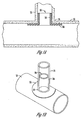
- Figure 1A is a sectional view of one embodiment of a brim-style junction liner 20 shown installed at the junction 14 of a main sewer pipe 10 and a lateral sewer pipe 12.
- the present invention includes the use of a brim- style junction liner 20 that includes a tubular portion 24 within the lateral pipe 12 adjacent the junction 14, and a flange or brim portion 22 within the main pipe 10 adjacent the junction 14.
- Figure 1B shows the same assembly of Figure 1A , depicted as a partial sectional perspective view, wherein the brim-style junction liner 20 is shown installed at a junction 14 of a main sewer pipe 10 and a lateral sewer pipe 12.
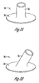
- Figures 2A-2B depict perspective views of an embodiment of a brim- style junction liner 20 prior to installation within a pipe.
- Figure 2A shows a brim-style junction liner 20 configured for installation within a standard tee-junction
- Figure 2B shows a configuration for installation within a wye-junction.
- a tee-junction of a pipe and a second structure may be generally described as a junction where the pipe joins the second structure at approximately a 90-degree angle.
- a wye-junction of a pipe and a second structure may be generally described as a junction where the pipe joins the second structure at an angle greater or less than approximately 90-degrees.
- the brim-style liner junction liner 20 comprises a tubular portion 24 and a brim portion 22.
- a brim is considered to be a projecting rim or edge extending outwardly from the tubular portion.
- the tubular portion 24 and brim portion 22 of the brim- style junction liner 20 are a single, unitary piece that may be constructed by a variety of methods.
- the brim-style junction liner 20 may be a cured-in-place liner comprising a fabric capable of holding a resinous material capable of curing and hardening.
- the fabric of the brim-style junction liner 20 may be knitted or otherwise formed as a single piece into the configurations shown in Figures 2A-2B .
- the brim-style junction liner 20 may alternatively be formed by attaching the tubular portion 24 to the brim portion 22.
- the tubular portion 24 may be formed by cutting a flat sheet of fabric to a specified size, forming the flat sheet into a tube, and sealing the ends of the sheet by stitching, adhesives, curable laminate films, flame bonding, heat welding, any combination of the foregoing, or the like.
- the brim portion 22 is formed by cutting a hole into a sheet of fabric.
- the sheet may be many shapes, but an annular shape is preferred, with the diameter of an inner circle of the annulus similar to the diameter of the tubular portion 24.
- An end of the tubular portion 24 is joined to the brim portion 22 at the inner circle of the annulus by stitching, adhesives, curable laminate films, flame bonding, heat welding, any combination of the foregoing, or the like.
- One or more surfaces of the fabric of the brim-style junction liner 20 include a polymeric coating comprising an impervious polymeric coating or film, preferably a thermoplastic polyurethane ("TPU").
- the coating may be made of other polymeric materials, such as polyethylene (PE) or polyvinyl chloride (PVC).
- the polymeric coating may be any other polymer that can be coated onto a resin-absorbent fabric.
- some polymers that may be used to coat an absorbent fabric include polyurethanes, polyethylenes, polyvinylchlorides, butyls, rubbers, cellophane nitrates, neoprenes, polyester, or combinations thereof.
- TPU is preferred because TPU is an example of a polymeric material that may be left inside the junction after the lining process is complete, acting as a coating to the interior of the conduit. It should also be noted that the coating is not a requirement of the present invention, it is contemplated that the liner does not include any such coating on either side of the liner.
- Figure 3 is a sectional view of a junction 100 of a pipe 102 and a second structure 104, where a brim-style junction liner 110 having a brim portion 112 has been installed and mechanical anchors 114 have been driven through the brim portion 112 of the liner 110 and at least partially into the wall of the second structure 104.
- the pipe 102 may be a sewer pipe, a service pipe, a gas pipe, a pressure pipe, or any other conduit adjoined at a junction with a second structure.
- the second structure 104 may be a manhole wall, a pipe, a service pipe, a gas pipe, a pressure pipe, or any other structure adjoined with a pipe. However, second structure 104 is generally depicted as a pipe.
- the mechanical anchors 114 of the present embodiment do not penetrate through the entire thickness of the second structure 104. Put another way, the mechanical anchors do not extend through both sides of the second structure. Such a configuration is preferred in this embodiment to prevent leakage of fluid within the junction at the penetration points of the mechanical anchors 114. Accordingly, a mechanical anchor 114 having a length less than the thickness of the brim portion 112 and second structure 104 is utilized in this embodiment. Where the mechanical anchors 114 penetrate the wall of the second structure 104 completely, the incorporation of a gasket material is preferred as described in reference to subsequent embodiments.
- the mechanical anchors 114 may be installed by a variety of methods. If the second structure 104 is generally accessible to a tool operator (such as via a manhole), then a drill, hammer, ratchet, screwdriver, or other tool may be used to drive the mechanical anchors 114 at least partially into the wall of the second structure 104, securing the brim portion 112 to the wall of the second structure 104.
- the mechanical anchor 114 may be a screw, nail, rivet, or other fastener adapted to secure two components.
- the second structure includes a wall comprising concrete, any anchor capable of penetrating and securing a compression member and/or liner to the second structure.
- an anchor nail may be used as the mechanical anchor 114.
- the anchor nail comprises a nail body including anchor nubs that run the length of the nail body, and a flange portion.
- the brim-style junction liner is placed at a junction using methods known in the art. The anchor nail is driven through the brim and at least partially through the second structure 104 by imparting a force on the flange of the nail in the direction of the host pipe using a driver tool until the flange portion of the anchor nail abuts the brim portion 112 of the liner 110.
- a driver tool for use in this embodiment may be a hammer or an auto hammer.
- the driver tool may be secured to a robot for use in pipelining applications where the pipe diameter restricts operator access to the junction.
- U.S. Patent Numbers 6,031,371 ; 6,101,951 ; and 7,720,570 disclose robots designed for pipelining or sewer applications with the capability for including interchangeable tools on board the robot.
- Such a driver tool may optionally be fitted to automatically re-load a mechanical fastener while within the pipeline.
- an operator may manually re-load the driver tool after each anchor is installed near the junction.
- Figure 4 shows a sectional view of a brim-style junction liner 200 having a brim portion 202 and a tubular portion 204 installed in conjunction with a compression gasket 210 at a junction 224 of a main sewer pipe 220 and a lateral sewer pipe 230.
- Mechanical anchors 212, 214 are installed through the compression gasket 210 and at least partially through a wall of the main sewer pipe 220.
- the brim- style junction liner 200 is a cured- in- place pipeline that has been installed at the junction over the compression gasket 210 using a cured-in-place pipelining technique. In cured-in-place pipelining, a bladder or other inflation member is used to press the liner against the pipe walls.
- a liner is impregnated with a resinous material capable of curing and hardening and secured with the bladder or inflation member.
- the liner, bladder, and placement device are positioned near the junction and the bladder is inflated, pushing the resin-impregnated liner against the walls of the junction.
- the resinous material is then cured and allowed to harden, creating a new interior of the junction.
- the placement of the compression gasket 210 between the brim- style junction liner 200 and the wall of the main and lateral pipes 220, 230 allows a compression seal to be created between the walls of the junction 224 and the brim-style junction liner 200.
- the mechanical anchors 212, 214 are placed through the compression gasket 210 and at least partially into or through the main sewer pipe 220.
- the compression gasket 210 includes an upper portion 216 and a lower portion 218, wherein the upper portion 216 extends at least partially into the lateral sewer pipe 230 and the lower portion 218 extends at least partially into the main sewer pipe 220.
- This configuration of the compression gasket 210 provides a compression seal to the majority of the area at junction 224, effectively sealing the entire area that is high risk for fluid infiltration.
- the configuration of the compression gasket 210 is for illustrative purposes, and other configurations of the compression gasket 210 are contemplated for use with this invention.
- the compression gasket 210 could be ring-shaped, attached directly to the brim-style junction liner 200, and placed between the brim-style junction liner 200 and the main sewer pipe 220 or lateral sewer pipe 230.
- the compression gasket 210 comprises a compliant, compressible, impermeable material including, but not limited to, rubber, polyurethane, or other compliant polymers.
- Compression gasket 210 may also be made of or impregnated with a material having hydrophilic properties, such that the material will swell in the presence of water. Such a material is preferred when the junction to be sealed experiences or is at risk of experiencing consistent water infiltration, as the hydrophilic gasket will expand in the presence of water and extrude through voids or cracks in the passageway, thus creating a full compression seal.
- hydrophilic materials for use as seals see U.S. Pat. No. 6,328,310 ; 6,541,106 ; or 6,994,118 .
- the compression gasket may be constructed of or coated in a hydrophobic material to repel the water from the junction under normal or dry conditions.
- any seal created by the brim-style junction liner 200 will be breached at the location of the anchors. Therefore, the compression gasket 210 will swell in the presence of water, negating the leaking effect created by insertion of the mechanical anchors 212, 214.
- the operation of the embodiment depicted in Figures 4 and 7 is as follows.
- the brim- style junction liner 200 is impregnated with a resinous material capable of curing and hardening.
- the upper portion 216 of a compression gasket 210 is placed against the wall of a lateral sewer pipe 230 and the lower portion 218 of the compression gasket 210 is placed against the wall of a main sewer pipe 220 such that the interior of the junction 224 is covered by the compression gasket 210.
- a brim-style junction liner 200 having a brim portion 202 and a tubular portion 204 is placed over the compression gasket 210, such that the brim-style junction liner 200 extends beyond the compression gasket 210 in both the main and lateral pipes.
- the brim-style junction liner 200 is pressed against the walls of the main sewer pipe 220 and the lateral sewer pipe 230 under fluid pressure, and the resinous material capable of curing and hardening is allowed to cure and harden.
- Mechanical anchors 212, 214 are inserted through the brim portion 202 of the brim-style junction liner 200, the lower portion 218 of the compression gasket 210, and at least partially into the main sewer pipe 220. It is preferred to use a plurality of mechanical anchors at diametrically opposed installation sites with respect to the junction diameter. Such a configuration of mechanical anchors will decrease the chance of weak points developing along the brim portion, breaching the seal.
- the brim portion 202 of the liner is generally circular shaped, it is contemplated that a number of mechanical anchors will be inserted through the brim and spaced radially about the axis of the brim.
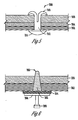
- Figure 5 depicts an example of an embodiment of a mechanical anchor 308 adapted to clamp a liner 302 to a wall of a pipe or second structure 300.
- the mechanical anchor 308 comprises an outer anchor portion 310, an anchor body 312, and a driver portion 314.
- the mechanical anchor 308 is depicted as passing completely through the liner 302, a compression gasket 304, and the second structure 300.
- the driver portion 314 of the mechanical anchor 308 preferably includes a substantial shoulder to secure the anchor against the inner surface of the liner 302.
- a drill may be used to provide a hole through the liner 302 and the second structure 300. The diameter of the hole should be large enough to allow for the passage of the outer anchor portion 310 and the anchor body 312 therethrough.
- the outer anchor portion 310 is passed through the hole, and the driver portion 314 of the mechanical fastener may be actuated by a driver tool on board a robot such that the outer anchor portion 310 deploys against the opposite surface of the second structure 300.
- a driver tool on board a robot such that the outer anchor portion 310 deploys against the opposite surface of the second structure 300.
- an anchor nail as described in U.S. Patent 4,611,964 , could be used in a similar manner.
- the compression gasket 304 may be hydrophilic such that it will swell in the presence of water to create a compression seal at the penetration point of the mechanical anchor 308.
- Figure 6 is a sectional view of a mechanical anchor 360 according to another embodiment of the invention, where a compression gasket 354 is disposed between a shoulder 364 of the mechanical anchor 360 and a pipe liner 352.
- the mechanical anchor 360 comprises an anchor body 362, a shoulder 364, and a driver portion 366.
- the mechanical anchor 360 is depicted as passing completely through the liner 352, the compression gasket 354, and the pipe or other structure 350.
- the driver portion 366 of the mechanical anchor 360 may be removed by a robot or operator by fatiguing the driver portion 366 from the shoulder 364 of the mechanical fastener 360.
- the compression gasket 354 may be hydrophilic and swell in the presence of water to create a compression seal at the penetration point of the mechanical anchor 360.
- a junction of a pipe and a second structure is sealed.
- the junction is visually inspected by a technician or operator either manually or with the aid of a closed-circuit television ("CCTV") camera system.
- CCTV closed-circuit television
- a brim- style pipe liner is provided having dimensions that generally conform to the dimensions of the junction.
- the pipe liner is then placed against an interior wall of the pipe, placing the brim portion against the second structure.
- the brim portion is then secured to the second structure using a mechanical anchor.
- the mechanical anchor should pass at least partially through the second structure.
- a compression gasket may be placed between the brim portion of the pipe liner and the second structure.
- a compression gasket may be placed between a shoulder of the mechanical anchor and the pipe liner.
Landscapes
- Engineering & Computer Science (AREA)
- General Engineering & Computer Science (AREA)
- Mechanical Engineering (AREA)
- Lining Or Joining Of Plastics Or The Like (AREA)
- Pipe Accessories (AREA)
Claims (15)
- Ensemble pour étanchéiser une jonction (14, 100, 224) d'une conduite (12, 102, 230) et d'une deuxième structure (10, 104, 220) comprenant :un revêtement de conduite (20, 110, 200, 352) ayant une portion tubulaire (24, 204) et une portion rebord (22, 112, 202) ; etun ancrage mécanique (114, 212, 214, 308, 360), caractérisé en ce qu'au moins une portion de l'ancrage mécanique (114, 212, 214, 308, 360) est conçu pour être enfoncée à travers la portion rebord (22, 112, 202) lors de l'utilisation afin d'assujettir la portion rebord (22, 112, 202) du revêtement de conduite (20, 110, 200, 352) sur la deuxième structure (10, 104, 220).
- Ensemble selon la revendication 1, comprenant en outre une garniture de compression (210, 354) destinée à être placée entre le revêtement de conduite (20, 110, 200, 352) et la conduite ou deuxième structure (10, 104, 220).
- Ensemble selon la revendication 2, la garniture de compression (210, 354) comprenant une matière hydrophile, une matière hydrophobe ou une matière compressible.
- Ensemble selon la revendication 1, ladite au moins portion de l'ancrage mécanique (114, 212, 214, 308, 360) étant conçue pour être enfoncée au moins partiellement dans une paroi de la deuxième structure (10, 104, 220) lors de l'utilisation.
- Ensemble selon la revendication 1, la conduite (12, 102, 230) étant une conduite d'égout latérale et la deuxième structure (10, 104, 220) étant une conduite d'égout principale.
- Ensemble selon la revendication 5, l'ancrage mécanique (114, 212, 214, 308, 360) comprenant un corps d'ancrage (312, 362), un épaulement (364) et une portion d'enfoncement (314, 366).
- Ensemble selon la revendication 1, le revêtement de conduite (20, 110, 200, 352) étant un revêtement de conduite séché sur place.
- Procédé d'étanchéisation d'une jonction (14, 100, 224) d'une conduite (12, 102, 230) et d'une deuxième structure (10, 104, 220) comprenant les opérations consistant à : mettre à disposition un revêtement de conduite (20, 110, 200, 352) ayant une portion tubulaire (24, 204) et une portion rebord (22, 112, 202) ;
placer la portion tubulaire (24, 204) du revêtement de conduite (20, 110, 200, 352) contre une paroi intérieure de la conduite (12, 102, 230) ;
placer la portion rebord (22, 112, 202) contre la deuxième structure (10, 104, 220) ; et
assujettir la portion rebord (22, 112, 202) sur la deuxième structure (10, 104, 220) en utilisant un ancrage mécanique (114, 212, 214, 308, 360), caractérisé en ce qu'au moins une portion de l'ancrage mécanique (114, 212, 214, 308, 360) est conçue de façon à être enfoncée à travers la portion rebord (22, 112, 202) afin d'assujettir la portion rebord (22, 112, 202) du revêtement de conduite (20, 110, 200, 352) sur la deuxième structure (10, 104, 220). - Procédé selon la revendication 8, comprenant en outre l'opération consistant à placer une garniture de compression (210, 354) entre la portion rebord (22, 112, 202) du revêtement de conduite (20, 110, 200, 352) et la deuxième structure (10, 104, 220).
- Procédé selon la revendication 9, la garniture de compression (210, 354) comprenant une matière hydrophile, une matière hydrophobe ou une matière compressible.
- Procédé selon la revendication 8, la conduite (12, 102, 230) étant une conduite d'égout latérale et la deuxième structure (10, 104, 220) étant une conduite d'égout principale.
- Procédé selon la revendication 8, le revêtement de conduite (20, 110, 200, 352) étant un revêtement de conduite séché sur place.
- Procédé selon la revendication 12, l'étape d'assujettissement comprenant l'enfoncement de ladite au moins portion de l'ancrage mécanique (114, 212, 214, 308, 360) à travers la portion rebord (22, 112, 202) et au moins une portion de la deuxième structure (10, 104, 220) après qu'une résine imprégnée au sein du revêtement de conduite séché sur place se soit durcie.
- Procédé selon la revendication 13, comprenant en outre l'opération consistant à insérer ladite au moins portion de l'ancrage mécanique (114, 212, 214, 308, 360) à travers une garniture de compression (210, 354) placée entre la portion rebord (22, 112, 202) du revêtement de conduite (20, 110, 200, 352) et la deuxième structure (10, 104, 220).
- Procédé selon la revendication 8, l'étape d'assujettissement comprenant l'enfoncement de ladite au moins portion de l'ancrage mécanique (114, 212, 214, 308, 360) au moins partiellement dans une paroi de la deuxième structure (10, 104, 220).
Applications Claiming Priority (2)
| Application Number | Priority Date | Filing Date | Title |
|---|---|---|---|
| US13/429,060 US9791089B2 (en) | 2012-03-23 | 2012-03-23 | Method and apparatus for repairing a pipe junction |
| PCT/US2013/031207 WO2013142231A1 (fr) | 2012-03-23 | 2013-03-14 | Procédé et appareil pour réparer un raccordement de tube |
Publications (2)
| Publication Number | Publication Date |
|---|---|
| EP2828567A1 EP2828567A1 (fr) | 2015-01-28 |
| EP2828567B1 true EP2828567B1 (fr) | 2016-11-09 |
Family
ID=48093078
Family Applications (1)
| Application Number | Title | Priority Date | Filing Date |
|---|---|---|---|
| EP13716091.7A Not-in-force EP2828567B1 (fr) | 2012-03-23 | 2013-03-14 | Procédé et appareil pour réparer un raccordement de tube |
Country Status (6)
| Country | Link |
|---|---|
| US (2) | US9791089B2 (fr) |
| EP (1) | EP2828567B1 (fr) |
| AU (2) | AU2013235552B2 (fr) |
| CA (2) | CA2868347C (fr) |
| DK (1) | DK2828567T3 (fr) |
| WO (1) | WO2013142231A1 (fr) |
Cited By (1)
| Publication number | Priority date | Publication date | Assignee | Title |
|---|---|---|---|---|
| CN106583630A (zh) * | 2016-12-29 | 2017-04-26 | 上海德朗汽车零部件制造有限公司 | 一种散热器水室水管角度定位铆接工装 |
Families Citing this family (17)
| Publication number | Priority date | Publication date | Assignee | Title |
|---|---|---|---|---|
| US8316892B2 (en) * | 2007-04-03 | 2012-11-27 | Liqui-Force Sewer Services Inc. | Lateral liner with seal |
| US7975726B2 (en) | 2007-08-27 | 2011-07-12 | Lmk Enterprises, Inc. | Device and method for repairing pipe |
| US9506596B2 (en) * | 2010-10-06 | 2016-11-29 | Lmk Technologies, Llc | Apparatus and method for repairing the junction of a sewer main and lateral pipe |
| US9945505B2 (en) | 2015-05-15 | 2018-04-17 | Lmk Technologies, Llc | Method and apparatus for repairing a pipe using a transition tube |
| US20170146178A1 (en) * | 2015-11-10 | 2017-05-25 | Lmk Technologies, Llc | Method and Apparatus for Repairing a Pipe Junction |
| DE102015122407A1 (de) * | 2015-12-21 | 2017-06-22 | Werner Zimmer | Verfahren zur Verbindung eines Kanalrohrs mit einem Anschlussrohr |
| NO20160491A1 (no) * | 2016-03-29 | 2017-09-11 | Olimb Group As | System og fremgangsmåte for gravefri renovasjon av anboringsklammer |
| CA2974678A1 (fr) | 2016-07-28 | 2018-01-28 | BLD Services, LLC | Systemes de revetement interieur de tuyau et methodes d'utilisation |
| CN106195639A (zh) * | 2016-08-25 | 2016-12-07 | 山东钢铁股份有限公司 | 煤气排水器下降管阀门在线更换装置 |
| US9933105B1 (en) * | 2017-04-12 | 2018-04-03 | InnerCure Technologies, LLC | Underground pipe repair device with radial stepped annular spacer and related systems and methods |
| US10514125B1 (en) | 2017-04-12 | 2019-12-24 | InnerCure Technologies, LLC | Underground pipe repair device with retention device and related systems and methods |
| US11326732B2 (en) | 2017-04-12 | 2022-05-10 | improved Infrastructure Solutions, LLC | Underground pipe repair device with detectable annular body and related systems and methods |
| US10309575B2 (en) | 2017-04-12 | 2019-06-04 | Inner Cure Technologies | Underground pipe repair device with radial annular spacers and related systems and methods |
| US10436374B2 (en) | 2017-10-09 | 2019-10-08 | Lmk Technologies, Llc | Grooved sealing member for sealing pipes and other underground structures and method of using |
| US10683959B2 (en) | 2017-10-17 | 2020-06-16 | Lmk Technologies, Llc | Method and apparatus for repairing a length of pipe or a main/lateral pipe junction |
| JP7439452B2 (ja) * | 2019-10-28 | 2024-02-28 | 中国電力株式会社 | 枝管残存部の閉塞構造、及び閉塞方法 |
| EP4105536A1 (fr) * | 2021-06-16 | 2022-12-21 | Wirth Fulda GmbH | Manchon d'insertion de tube destiné à la réparation des branchements tubulaires d'une tuyauterie, procédé d'assainissement des branchements tubulaires d'une tuyauterie, ainsi qu'utilisation d'un insert de tube selon l'invention pour l'assainissement d'une tuyauterie dotée d'un piquage tubulaire |
Family Cites Families (29)
| Publication number | Priority date | Publication date | Assignee | Title |
|---|---|---|---|---|
| US1861726A (en) * | 1927-02-16 | 1932-06-07 | Chester A Rasmussen | Blow-out preventer |
| US1881717A (en) * | 1929-03-07 | 1932-10-11 | Dempster Mill Mfg Company | Well casing joint |
| US4522432A (en) | 1982-04-21 | 1985-06-11 | Umc Industries, Inc. | Components for lined piping system with anchored liners and method of manufacture |
| US5340160A (en) | 1989-11-21 | 1994-08-23 | Wavin B.V. | Thermoplastic saddle in two parts for repairing or renovating a pipe line with branch pipe and repaired or renovated pipe with a saddle |
| GB9009073D0 (en) | 1990-04-23 | 1990-06-20 | Insituform Group Ltd | Improvements relating to the lining of pipelines or passageways |
| US6337114B1 (en) | 1992-09-10 | 2002-01-08 | Insituform (Netherlands) B.V. | Flexible lining with flexible collar for lining lateral pipelines |
| DE4421290A1 (de) | 1994-06-17 | 1995-12-21 | Hans Dipl Ing Dammer | Verfahren für die Abdichtung insbesondere von Kanalrohren |
| JP2605220B2 (ja) | 1994-07-05 | 1997-04-30 | 株式会社湘南合成樹脂製作所 | 枝管ライニング工法 |
| US5794663A (en) | 1994-08-19 | 1998-08-18 | Lmk Enterprises | Apparatus for repairing a pipeline and method for using same |
| US5950682A (en) | 1994-08-19 | 1999-09-14 | Lmk Enterprises, Inc. | Apparatus and method for repairing the junction of a sewer main line and lateral |
| US5511573A (en) * | 1994-10-24 | 1996-04-30 | K N Energy, Inc. | Contaminated valve containment device |
| GB2301187B (en) | 1995-05-22 | 1999-04-21 | British Gas Plc | Method of and apparatus for locating an anomaly in a duct |
| US5916406A (en) | 1996-02-14 | 1999-06-29 | Shonan Gosei-Jushi Seisakusho Kk | Branch pipe liner bag and pipe lining method |
| DE29700298U1 (de) | 1997-01-10 | 1998-05-07 | Scheiff GmbH, 53881 Euskirchen | Roboter zur Kanalsanierung |
| JPH10278115A (ja) * | 1997-02-04 | 1998-10-20 | Shonan Gosei Jushi Seisakusho:Kk | 枝管ライニング材及び管ライニング工法 |
| US5944058A (en) * | 1997-02-04 | 1999-08-31 | Shonan Gosei-Jushi Seisakusho K.K. | Branch pipe liner assembly and a pipe lining method |
| JPH10281380A (ja) * | 1997-04-11 | 1998-10-23 | Suido Gijutsu Kaihatsu Kiko:Kk | 分岐管の接続構造 |
| US5915419A (en) | 1997-11-26 | 1999-06-29 | Insituform (Netherlands) B.V. | Cured in place lateral seal for relining of pipelines and method of manufacture |
| US6039079A (en) | 1998-07-17 | 2000-03-21 | Lmk Enterprises, Inc. | Apparatus and method for repairing the junction of a sewer main line and lateral pipe |
| JP2000052426A (ja) * | 1998-08-06 | 2000-02-22 | Shonan Gosei Jushi Seisakusho:Kk | 枝管ライニング材及び管ライニング工法 |
| US5971032A (en) | 1998-11-20 | 1999-10-26 | Tele Environmental Systems | Apparatus and method for the robotic repairing of an underground pipe junction |
| JP2000220752A (ja) | 1999-02-03 | 2000-08-08 | Akashiya Kako Kk | 防水用シール部材を用いる止水方法 |
| IT247484Y1 (it) | 1999-07-22 | 2002-08-22 | Redi Spa | Raccordo per la realizzazione di diramazioni da tubi . |
| US6541106B1 (en) | 2000-09-12 | 2003-04-01 | The United States Of America As Represented By The Secretary Of The Interior | Hydrophilic polyurethane impregnated rubber for sealing water leaks |
| US6688337B2 (en) | 2001-12-19 | 2004-02-10 | Robert M. Ward | Apparatus and method for the robotic repairing of an underground pipe junction with a flexible patch mechanism |
| US6994118B2 (en) | 2003-12-04 | 2006-02-07 | Blue Sky Forever, Inc. | Device and method for repairing pipe using hydrophilic seals |
| US7720570B2 (en) | 2004-10-01 | 2010-05-18 | Redzone Robotics, Inc. | Network architecture for remote robot with interchangeable tools |
| DE102005060543A1 (de) | 2005-12-17 | 2007-06-28 | Brandenburger Patentverwertung Gbr (Vertretungsberechtigte Gesellschafter Herr Joachim Brandenburger | Verfahren zum Sanieren von Abzweigleitungen von Kanalrohren |
| JP2007283572A (ja) | 2006-04-14 | 2007-11-01 | Shonan Plastic Mfg Co Ltd | 管ライニング工法 |
-
2012
- 2012-03-23 US US13/429,060 patent/US9791089B2/en active Active
-
2013
- 2013-03-14 DK DK13716091.7T patent/DK2828567T3/en active
- 2013-03-14 WO PCT/US2013/031207 patent/WO2013142231A1/fr not_active Ceased
- 2013-03-14 CA CA2868347A patent/CA2868347C/fr active Active
- 2013-03-14 CA CA2952257A patent/CA2952257C/fr active Active
- 2013-03-14 EP EP13716091.7A patent/EP2828567B1/fr not_active Not-in-force
- 2013-03-14 AU AU2013235552A patent/AU2013235552B2/en not_active Ceased
-
2016
- 2016-12-15 AU AU2016273919A patent/AU2016273919A1/en not_active Abandoned
-
2017
- 2017-09-21 US US15/711,762 patent/US20180010725A1/en not_active Abandoned
Non-Patent Citations (1)
| Title |
|---|
| None * |
Cited By (2)
| Publication number | Priority date | Publication date | Assignee | Title |
|---|---|---|---|---|
| CN106583630A (zh) * | 2016-12-29 | 2017-04-26 | 上海德朗汽车零部件制造有限公司 | 一种散热器水室水管角度定位铆接工装 |
| CN106583630B (zh) * | 2016-12-29 | 2019-11-19 | 上海德朗汽车零部件制造有限公司 | 一种散热器水室水管角度定位铆接工装 |
Also Published As
| Publication number | Publication date |
|---|---|
| CA2868347C (fr) | 2017-01-17 |
| AU2016273919A1 (en) | 2017-01-12 |
| CA2952257A1 (fr) | 2013-09-26 |
| AU2013235552B2 (en) | 2016-09-15 |
| US20130249208A1 (en) | 2013-09-26 |
| EP2828567A1 (fr) | 2015-01-28 |
| AU2013235552A1 (en) | 2014-10-16 |
| US20180010725A1 (en) | 2018-01-11 |
| WO2013142231A1 (fr) | 2013-09-26 |
| CA2868347A1 (fr) | 2013-09-26 |
| CA2952257C (fr) | 2018-08-28 |
| US9791089B2 (en) | 2017-10-17 |
| DK2828567T3 (en) | 2016-12-12 |
Similar Documents
| Publication | Publication Date | Title |
|---|---|---|
| CA2868347C (fr) | Procede et appareil pour reparer un raccordement de tube | |
| US20170146178A1 (en) | Method and Apparatus for Repairing a Pipe Junction | |
| CA2714404C (fr) | Dispositif et procede permettant la reparation de conduite | |
| EP2185854B1 (fr) | Procede de reparation de conduites | |
| US10495249B2 (en) | Means and method for lining a pipe | |
| US8715800B2 (en) | Apparatus and method to repair the junction of a sewer main line and lateral pipe | |
| US20100187813A1 (en) | Connector for Interconnecting A Lateral Pipe to A Main Pipe | |
| JP2005336891A (ja) | 既設管の更生工法 | |
| US10683959B2 (en) | Method and apparatus for repairing a length of pipe or a main/lateral pipe junction | |
| EP0911568B1 (fr) | Dispositif de revêtement d'un tuyau de dérivation et procédé pour le revêtement d'un tuyau |
Legal Events
| Date | Code | Title | Description |
|---|---|---|---|
| PUAI | Public reference made under article 153(3) epc to a published international application that has entered the european phase |
Free format text: ORIGINAL CODE: 0009012 |
|
| 17P | Request for examination filed |
Effective date: 20141021 |
|
| AK | Designated contracting states |
Kind code of ref document: A1 Designated state(s): AL AT BE BG CH CY CZ DE DK EE ES FI FR GB GR HR HU IE IS IT LI LT LU LV MC MK MT NL NO PL PT RO RS SE SI SK SM TR |
|
| AX | Request for extension of the european patent |
Extension state: BA ME |
|
| DAX | Request for extension of the european patent (deleted) | ||
| 17Q | First examination report despatched |
Effective date: 20151029 |
|
| GRAP | Despatch of communication of intention to grant a patent |
Free format text: ORIGINAL CODE: EPIDOSNIGR1 |
|
| GRAS | Grant fee paid |
Free format text: ORIGINAL CODE: EPIDOSNIGR3 |
|
| GRAJ | Information related to disapproval of communication of intention to grant by the applicant or resumption of examination proceedings by the epo deleted |
Free format text: ORIGINAL CODE: EPIDOSDIGR1 |
|
| GRAL | Information related to payment of fee for publishing/printing deleted |
Free format text: ORIGINAL CODE: EPIDOSDIGR3 |
|
| INTG | Intention to grant announced |
Effective date: 20160809 |
|
| GRAP | Despatch of communication of intention to grant a patent |
Free format text: ORIGINAL CODE: EPIDOSNIGR1 |
|
| INTC | Intention to grant announced (deleted) | ||
| GRAA | (expected) grant |
Free format text: ORIGINAL CODE: 0009210 |
|
| INTG | Intention to grant announced |
Effective date: 20160916 |
|
| AK | Designated contracting states |
Kind code of ref document: B1 Designated state(s): AL AT BE BG CH CY CZ DE DK EE ES FI FR GB GR HR HU IE IS IT LI LT LU LV MC MK MT NL NO PL PT RO RS SE SI SK SM TR |
|
| REG | Reference to a national code |
Ref country code: GB Ref legal event code: FG4D |
|
| REG | Reference to a national code |
Ref country code: AT Ref legal event code: REF Ref document number: 844273 Country of ref document: AT Kind code of ref document: T Effective date: 20161115 Ref country code: CH Ref legal event code: EP |
|
| REG | Reference to a national code |
Ref country code: IE Ref legal event code: FG4D |
|
| REG | Reference to a national code |
Ref country code: DK Ref legal event code: T3 Effective date: 20161208 |
|
| REG | Reference to a national code |
Ref country code: CH Ref legal event code: NV Representative=s name: MICHELI AND CIE SA, CH |
|
| REG | Reference to a national code |
Ref country code: DE Ref legal event code: R096 Ref document number: 602013013787 Country of ref document: DE |
|
| REG | Reference to a national code |
Ref country code: FR Ref legal event code: PLFP Year of fee payment: 5 |
|
| PG25 | Lapsed in a contracting state [announced via postgrant information from national office to epo] |
Ref country code: LV Free format text: LAPSE BECAUSE OF FAILURE TO SUBMIT A TRANSLATION OF THE DESCRIPTION OR TO PAY THE FEE WITHIN THE PRESCRIBED TIME-LIMIT Effective date: 20161109 |
|
| REG | Reference to a national code |
Ref country code: LT Ref legal event code: MG4D |
|
| REG | Reference to a national code |
Ref country code: NL Ref legal event code: MP Effective date: 20161109 |
|
| REG | Reference to a national code |
Ref country code: AT Ref legal event code: MK05 Ref document number: 844273 Country of ref document: AT Kind code of ref document: T Effective date: 20161109 |
|
| PG25 | Lapsed in a contracting state [announced via postgrant information from national office to epo] |
Ref country code: LT Free format text: LAPSE BECAUSE OF FAILURE TO SUBMIT A TRANSLATION OF THE DESCRIPTION OR TO PAY THE FEE WITHIN THE PRESCRIBED TIME-LIMIT Effective date: 20161109 Ref country code: NO Free format text: LAPSE BECAUSE OF FAILURE TO SUBMIT A TRANSLATION OF THE DESCRIPTION OR TO PAY THE FEE WITHIN THE PRESCRIBED TIME-LIMIT Effective date: 20170209 Ref country code: NL Free format text: LAPSE BECAUSE OF FAILURE TO SUBMIT A TRANSLATION OF THE DESCRIPTION OR TO PAY THE FEE WITHIN THE PRESCRIBED TIME-LIMIT Effective date: 20161109 Ref country code: GR Free format text: LAPSE BECAUSE OF FAILURE TO SUBMIT A TRANSLATION OF THE DESCRIPTION OR TO PAY THE FEE WITHIN THE PRESCRIBED TIME-LIMIT Effective date: 20170210 Ref country code: SE Free format text: LAPSE BECAUSE OF FAILURE TO SUBMIT A TRANSLATION OF THE DESCRIPTION OR TO PAY THE FEE WITHIN THE PRESCRIBED TIME-LIMIT Effective date: 20161109 |
|
| PGFP | Annual fee paid to national office [announced via postgrant information from national office to epo] |
Ref country code: DE Payment date: 20170307 Year of fee payment: 5 Ref country code: FR Payment date: 20170213 Year of fee payment: 5 Ref country code: CH Payment date: 20170314 Year of fee payment: 5 |
|
| PG25 | Lapsed in a contracting state [announced via postgrant information from national office to epo] |
Ref country code: HR Free format text: LAPSE BECAUSE OF FAILURE TO SUBMIT A TRANSLATION OF THE DESCRIPTION OR TO PAY THE FEE WITHIN THE PRESCRIBED TIME-LIMIT Effective date: 20161109 Ref country code: FI Free format text: LAPSE BECAUSE OF FAILURE TO SUBMIT A TRANSLATION OF THE DESCRIPTION OR TO PAY THE FEE WITHIN THE PRESCRIBED TIME-LIMIT Effective date: 20161109 Ref country code: PL Free format text: LAPSE BECAUSE OF FAILURE TO SUBMIT A TRANSLATION OF THE DESCRIPTION OR TO PAY THE FEE WITHIN THE PRESCRIBED TIME-LIMIT Effective date: 20161109 Ref country code: IS Free format text: LAPSE BECAUSE OF FAILURE TO SUBMIT A TRANSLATION OF THE DESCRIPTION OR TO PAY THE FEE WITHIN THE PRESCRIBED TIME-LIMIT Effective date: 20170309 Ref country code: AT Free format text: LAPSE BECAUSE OF FAILURE TO SUBMIT A TRANSLATION OF THE DESCRIPTION OR TO PAY THE FEE WITHIN THE PRESCRIBED TIME-LIMIT Effective date: 20161109 Ref country code: PT Free format text: LAPSE BECAUSE OF FAILURE TO SUBMIT A TRANSLATION OF THE DESCRIPTION OR TO PAY THE FEE WITHIN THE PRESCRIBED TIME-LIMIT Effective date: 20170309 Ref country code: RS Free format text: LAPSE BECAUSE OF FAILURE TO SUBMIT A TRANSLATION OF THE DESCRIPTION OR TO PAY THE FEE WITHIN THE PRESCRIBED TIME-LIMIT Effective date: 20161109 Ref country code: ES Free format text: LAPSE BECAUSE OF FAILURE TO SUBMIT A TRANSLATION OF THE DESCRIPTION OR TO PAY THE FEE WITHIN THE PRESCRIBED TIME-LIMIT Effective date: 20161109 |
|
| PGFP | Annual fee paid to national office [announced via postgrant information from national office to epo] |
Ref country code: DK Payment date: 20170310 Year of fee payment: 5 Ref country code: GB Payment date: 20170308 Year of fee payment: 5 |
|
| PGFP | Annual fee paid to national office [announced via postgrant information from national office to epo] |
Ref country code: IT Payment date: 20170320 Year of fee payment: 5 |
|
| PG25 | Lapsed in a contracting state [announced via postgrant information from national office to epo] |
Ref country code: RO Free format text: LAPSE BECAUSE OF FAILURE TO SUBMIT A TRANSLATION OF THE DESCRIPTION OR TO PAY THE FEE WITHIN THE PRESCRIBED TIME-LIMIT Effective date: 20161109 Ref country code: EE Free format text: LAPSE BECAUSE OF FAILURE TO SUBMIT A TRANSLATION OF THE DESCRIPTION OR TO PAY THE FEE WITHIN THE PRESCRIBED TIME-LIMIT Effective date: 20161109 Ref country code: CZ Free format text: LAPSE BECAUSE OF FAILURE TO SUBMIT A TRANSLATION OF THE DESCRIPTION OR TO PAY THE FEE WITHIN THE PRESCRIBED TIME-LIMIT Effective date: 20161109 Ref country code: SK Free format text: LAPSE BECAUSE OF FAILURE TO SUBMIT A TRANSLATION OF THE DESCRIPTION OR TO PAY THE FEE WITHIN THE PRESCRIBED TIME-LIMIT Effective date: 20161109 |
|
| REG | Reference to a national code |
Ref country code: DE Ref legal event code: R097 Ref document number: 602013013787 Country of ref document: DE |
|
| PG25 | Lapsed in a contracting state [announced via postgrant information from national office to epo] |
Ref country code: BE Free format text: LAPSE BECAUSE OF FAILURE TO SUBMIT A TRANSLATION OF THE DESCRIPTION OR TO PAY THE FEE WITHIN THE PRESCRIBED TIME-LIMIT Effective date: 20161109 Ref country code: SM Free format text: LAPSE BECAUSE OF FAILURE TO SUBMIT A TRANSLATION OF THE DESCRIPTION OR TO PAY THE FEE WITHIN THE PRESCRIBED TIME-LIMIT Effective date: 20161109 Ref country code: BG Free format text: LAPSE BECAUSE OF FAILURE TO SUBMIT A TRANSLATION OF THE DESCRIPTION OR TO PAY THE FEE WITHIN THE PRESCRIBED TIME-LIMIT Effective date: 20170209 |
|
| PLBE | No opposition filed within time limit |
Free format text: ORIGINAL CODE: 0009261 |
|
| STAA | Information on the status of an ep patent application or granted ep patent |
Free format text: STATUS: NO OPPOSITION FILED WITHIN TIME LIMIT |
|
| 26N | No opposition filed |
Effective date: 20170810 |
|
| PG25 | Lapsed in a contracting state [announced via postgrant information from national office to epo] |
Ref country code: SI Free format text: LAPSE BECAUSE OF FAILURE TO SUBMIT A TRANSLATION OF THE DESCRIPTION OR TO PAY THE FEE WITHIN THE PRESCRIBED TIME-LIMIT Effective date: 20161109 Ref country code: MC Free format text: LAPSE BECAUSE OF FAILURE TO SUBMIT A TRANSLATION OF THE DESCRIPTION OR TO PAY THE FEE WITHIN THE PRESCRIBED TIME-LIMIT Effective date: 20161109 |
|
| REG | Reference to a national code |
Ref country code: IE Ref legal event code: MM4A |
|
| PG25 | Lapsed in a contracting state [announced via postgrant information from national office to epo] |
Ref country code: LU Free format text: LAPSE BECAUSE OF NON-PAYMENT OF DUE FEES Effective date: 20170314 |
|
| PG25 | Lapsed in a contracting state [announced via postgrant information from national office to epo] |
Ref country code: IE Free format text: LAPSE BECAUSE OF NON-PAYMENT OF DUE FEES Effective date: 20170314 |
|
| PG25 | Lapsed in a contracting state [announced via postgrant information from national office to epo] |
Ref country code: MT Free format text: LAPSE BECAUSE OF NON-PAYMENT OF DUE FEES Effective date: 20170314 |
|
| REG | Reference to a national code |
Ref country code: DE Ref legal event code: R119 Ref document number: 602013013787 Country of ref document: DE |
|
| REG | Reference to a national code |
Ref country code: DK Ref legal event code: EBP Effective date: 20180331 |
|
| REG | Reference to a national code |
Ref country code: CH Ref legal event code: PL |
|
| GBPC | Gb: european patent ceased through non-payment of renewal fee |
Effective date: 20180314 |
|
| PG25 | Lapsed in a contracting state [announced via postgrant information from national office to epo] |
Ref country code: DE Free format text: LAPSE BECAUSE OF NON-PAYMENT OF DUE FEES Effective date: 20181002 |
|
| PG25 | Lapsed in a contracting state [announced via postgrant information from national office to epo] |
Ref country code: GB Free format text: LAPSE BECAUSE OF NON-PAYMENT OF DUE FEES Effective date: 20180314 Ref country code: IT Free format text: LAPSE BECAUSE OF NON-PAYMENT OF DUE FEES Effective date: 20180314 Ref country code: LI Free format text: LAPSE BECAUSE OF NON-PAYMENT OF DUE FEES Effective date: 20180331 Ref country code: CH Free format text: LAPSE BECAUSE OF NON-PAYMENT OF DUE FEES Effective date: 20180331 |
|
| PG25 | Lapsed in a contracting state [announced via postgrant information from national office to epo] |
Ref country code: FR Free format text: LAPSE BECAUSE OF NON-PAYMENT OF DUE FEES Effective date: 20180331 |
|
| PG25 | Lapsed in a contracting state [announced via postgrant information from national office to epo] |
Ref country code: DK Free format text: LAPSE BECAUSE OF NON-PAYMENT OF DUE FEES Effective date: 20180331 |
|
| PG25 | Lapsed in a contracting state [announced via postgrant information from national office to epo] |
Ref country code: HU Free format text: LAPSE BECAUSE OF FAILURE TO SUBMIT A TRANSLATION OF THE DESCRIPTION OR TO PAY THE FEE WITHIN THE PRESCRIBED TIME-LIMIT; INVALID AB INITIO Effective date: 20130314 |
|
| PG25 | Lapsed in a contracting state [announced via postgrant information from national office to epo] |
Ref country code: CY Free format text: LAPSE BECAUSE OF FAILURE TO SUBMIT A TRANSLATION OF THE DESCRIPTION OR TO PAY THE FEE WITHIN THE PRESCRIBED TIME-LIMIT Effective date: 20161109 |
|
| PG25 | Lapsed in a contracting state [announced via postgrant information from national office to epo] |
Ref country code: MK Free format text: LAPSE BECAUSE OF FAILURE TO SUBMIT A TRANSLATION OF THE DESCRIPTION OR TO PAY THE FEE WITHIN THE PRESCRIBED TIME-LIMIT Effective date: 20161109 |
|
| PG25 | Lapsed in a contracting state [announced via postgrant information from national office to epo] |
Ref country code: TR Free format text: LAPSE BECAUSE OF FAILURE TO SUBMIT A TRANSLATION OF THE DESCRIPTION OR TO PAY THE FEE WITHIN THE PRESCRIBED TIME-LIMIT Effective date: 20161109 |
|
| PG25 | Lapsed in a contracting state [announced via postgrant information from national office to epo] |
Ref country code: AL Free format text: LAPSE BECAUSE OF FAILURE TO SUBMIT A TRANSLATION OF THE DESCRIPTION OR TO PAY THE FEE WITHIN THE PRESCRIBED TIME-LIMIT Effective date: 20161109 |