EP2828623B1 - Vorwärmer für adiabatische kühlanlagen - Google Patents
Vorwärmer für adiabatische kühlanlagen Download PDFInfo
- Publication number
- EP2828623B1 EP2828623B1 EP13720534.0A EP13720534A EP2828623B1 EP 2828623 B1 EP2828623 B1 EP 2828623B1 EP 13720534 A EP13720534 A EP 13720534A EP 2828623 B1 EP2828623 B1 EP 2828623B1
- Authority
- EP
- European Patent Office
- Prior art keywords
- water
- main body
- holes
- liquid
- electrodes
- Prior art date
- Legal status (The legal status is an assumption and is not a legal conclusion. Google has not performed a legal analysis and makes no representation as to the accuracy of the status listed.)
- Active
Links
Images



Classifications
-
- G—PHYSICS
- G01—MEASURING; TESTING
- G01F—MEASURING VOLUME, VOLUME FLOW, MASS FLOW OR LIQUID LEVEL; METERING BY VOLUME
- G01F1/00—Measuring the volume flow or mass flow of fluid or fluent solid material wherein the fluid passes through a meter in a continuous flow
- G01F1/56—Measuring the volume flow or mass flow of fluid or fluent solid material wherein the fluid passes through a meter in a continuous flow by using electric or magnetic effects
- G01F1/64—Measuring the volume flow or mass flow of fluid or fluent solid material wherein the fluid passes through a meter in a continuous flow by using electric or magnetic effects by measuring electrical currents passing through the fluid flow; measuring electrical potential generated by the fluid flow, e.g. by electrochemical, contact or friction effects
-
- F—MECHANICAL ENGINEERING; LIGHTING; HEATING; WEAPONS; BLASTING
- F24—HEATING; RANGES; VENTILATING
- F24F—AIR-CONDITIONING; AIR-HUMIDIFICATION; VENTILATION; USE OF AIR CURRENTS FOR SCREENING
- F24F5/00—Air-conditioning systems or apparatus not covered by F24F1/00 or F24F3/00, e.g. using solar heat or combined with household units such as an oven or water heater
- F24F5/0007—Air-conditioning systems or apparatus not covered by F24F1/00 or F24F3/00, e.g. using solar heat or combined with household units such as an oven or water heater cooling apparatus specially adapted for use in air-conditioning
- F24F5/0035—Air-conditioning systems or apparatus not covered by F24F1/00 or F24F3/00, e.g. using solar heat or combined with household units such as an oven or water heater cooling apparatus specially adapted for use in air-conditioning using evaporation
-
- F—MECHANICAL ENGINEERING; LIGHTING; HEATING; WEAPONS; BLASTING
- F24—HEATING; RANGES; VENTILATING
- F24F—AIR-CONDITIONING; AIR-HUMIDIFICATION; VENTILATION; USE OF AIR CURRENTS FOR SCREENING
- F24F6/00—Air-humidification, e.g. cooling by humidification
- F24F6/02—Air-humidification, e.g. cooling by humidification by evaporation of water in the air
- F24F6/04—Air-humidification, e.g. cooling by humidification by evaporation of water in the air using stationary unheated wet elements
- F24F6/043—Air-humidification, e.g. cooling by humidification by evaporation of water in the air using stationary unheated wet elements with self-sucking action, e.g. wicks
-
- G—PHYSICS
- G05—CONTROLLING; REGULATING
- G05D—SYSTEMS FOR CONTROLLING OR REGULATING NON-ELECTRIC VARIABLES
- G05D7/00—Control of flow
- G05D7/06—Control of flow characterised by the use of electric means
- G05D7/0617—Control of flow characterised by the use of electric means specially adapted for fluid materials
- G05D7/0629—Control of flow characterised by the use of electric means specially adapted for fluid materials characterised by the type of regulator means
- G05D7/0635—Control of flow characterised by the use of electric means specially adapted for fluid materials characterised by the type of regulator means by action on throttling means
-
- F—MECHANICAL ENGINEERING; LIGHTING; HEATING; WEAPONS; BLASTING
- F24—HEATING; RANGES; VENTILATING
- F24F—AIR-CONDITIONING; AIR-HUMIDIFICATION; VENTILATION; USE OF AIR CURRENTS FOR SCREENING
- F24F6/00—Air-humidification, e.g. cooling by humidification
- F24F2006/006—Air-humidification, e.g. cooling by humidification with water treatment
-
- F—MECHANICAL ENGINEERING; LIGHTING; HEATING; WEAPONS; BLASTING
- F24—HEATING; RANGES; VENTILATING
- F24F—AIR-CONDITIONING; AIR-HUMIDIFICATION; VENTILATION; USE OF AIR CURRENTS FOR SCREENING
- F24F2140/00—Control inputs relating to system states
- F24F2140/30—Condensation of water from cooled air
-
- H—ELECTRICITY
- H01—ELECTRIC ELEMENTS
- H01H—ELECTRIC SWITCHES; RELAYS; SELECTORS; EMERGENCY PROTECTIVE DEVICES
- H01H29/00—Switches having at least one liquid contact
- H01H29/02—Details
- H01H29/04—Contacts; Containers for liquid contacts
-
- Y—GENERAL TAGGING OF NEW TECHNOLOGICAL DEVELOPMENTS; GENERAL TAGGING OF CROSS-SECTIONAL TECHNOLOGIES SPANNING OVER SEVERAL SECTIONS OF THE IPC; TECHNICAL SUBJECTS COVERED BY FORMER USPC CROSS-REFERENCE ART COLLECTIONS [XRACs] AND DIGESTS
- Y02—TECHNOLOGIES OR APPLICATIONS FOR MITIGATION OR ADAPTATION AGAINST CLIMATE CHANGE
- Y02B—CLIMATE CHANGE MITIGATION TECHNOLOGIES RELATED TO BUILDINGS, e.g. HOUSING, HOUSE APPLIANCES OR RELATED END-USER APPLICATIONS
- Y02B30/00—Energy efficient heating, ventilation or air conditioning [HVAC]
- Y02B30/54—Free-cooling systems
Definitions
- the present invention relates to a device for detecting the presence of a flow of liquids and a cooling system comprising said device. More particularly, the device of the present invention carries out the function of economizer when installed in adiabatic cooling systems, thus it will be explained hereinafter, how said device carries out this function of economizer.
- cooling of a fluid or solid substance may be performed by the adiabatic effect, namely removal of the amount of thermal energy required for the evaporation of a desired mass of liquid in contact with said fluid or solid.
- This thermal energy also called latent heat, develops without any change of temperature of the evaporating liquid; conversely the fluid or solid to be cooled undergoes a temperature fall, since it has to yield a quantity of heat equal to that required for evaporation of the liquid contacted therewith.
- This principle is widely exploited in the cooling systems by means of refrigerating or evaporating equipments. The cooling capacity of these systems is proportional to the quantity of evaporated liquid.
- the amount of evaporated liquid is generally lower than the quantity of liquid entering the evaporation equipment.
- the deviation of evaporated liquid quantity relative to the quantity of entering liquid depends on the intrinsic efficiency of the evaporative equipment and the quality of the regulation system.
- the liquid most commonly used in the evaporation equipments is water, whose latent heat for conversion from liquid to steam and viceversa, is approximately 700 W/kg.
- the cooling systems of this kind are usually provided with humidity detection probes, which are activated by the detection of liquid, namely water, on them.
- humidity detection probes which are activated by the detection of liquid, namely water, on them.
- these probes are often subject to wrong surveys, because they can be activated even by the presence just of one single drop, which is however not representative of the general status of the system.
- these probes require a long time to become dry and again operative, thus clearly causing considerable operative defects of the system.
- JP 2000 300099 discloses a control device for air conditioner to solve the problem that the temperature of the electrical equipment of an outdoor unit exceeds an allowable temperature even in the condition in which an operating current (I) is low due to the small number of revolution (r) of an outdoor blower at the time of reheat dehumidifying operation so as to cause inconvenience to the electrical equipment of the outdoor unit in a conventional air conditioner.
- this document does not disclose a device for detecting passage of a liquid having electrically conducting elements being positioned at a reciprocal distance in the range of 5 mm to 15 mm determined by the thickness of the narrowing portion to detect at least the presence of a minimum level of detectable water flowing through the device.
- EP 0 733 884 discloses a quantity meter and an implement for milking animals, said implement being provided with such a meter.
- EP 0 509 288 discloses a method and apparatus for measuring a value corresponding to the mass of a milk plug as well as the milk flow.
- EP 0 795 268 discloses a quantity meter and an implement for milking animals comprising such a meter.
- US 5 192 464 discloses an evaporative cooler.
- US 4 994 211 discloses a water distribution apparatus for evaporative cooling system.
- the detection device of the present invention is advantageously used and here described as economizer of water consumption in evaporation equipments with water drain.
- the invention consists of a dielectric device, for instance made as a dielectric block comprising a pair of coaxial continuity sensors, aligned in a vertical discharge duct.
- the device comprises also a pair of electric terminals, to be connected to the regulation system of the evaporation equipment, for each sensor.
- the dielectric material of the device In absence of water or humidity the dielectric material of the device generates an electric resistance between the two sensors tending to infinity, while the presence of water on the passage surface between the sensors, generates an electric resistance varying from a minimum to a maximum as a function of the intensity of discharge.
- the logic of the regulation system of the evaporation equipment depends on the value of the electric resistance generated between the two sensors. A low value of electric resistance between the sensors tendentially causes a slackening of water irrigation in the evaporation equipment.
- the amount of water used in the evaporation equipments may also vary according to the required thermal power and the thermal-hygrometric conditions of the environment where the evaporation process takes place.
- an evaporation equipment may include a system for feeding water to be evaporated such as a duct, a nozzle, a container with holes or nozzles, a bored pipe, or one or more atomising nozzles, with or without air or water pressurizing devices, and an element on which water deposits temporarily during evaporation, it is known that said temporary deposit tends to fall downwards by gravity.
- a system for feeding water to be evaporated such as a duct, a nozzle, a container with holes or nozzles, a bored pipe, or one or more atomising nozzles, with or without air or water pressurizing devices, and an element on which water deposits temporarily during evaporation, it is known that said temporary deposit tends to fall downwards by gravity.
- the device of the present invention is adapted to be used in systems arranged in the external environment, without water storage.
- the present invention exploits the natural property of the drops of condensed water to slide downwards by gravity.
- the device according to the present invention is a detector of presence of a water flow (even if such a flow is very reduced but, according to standards set by the manufacturer, sufficient to establish that the system is saturated and feed of water to the system is no more required, before it has consumed the already supplied water quantity), so that when the device is activated and a signal of water presence is received, the device sends a signal of stopping water delivery to the system.
- the system sensitivity even to very reduced water quantities is indeed due to the fact that both the system and the device are arranged parallel to ground and more particularly the device axis X is perpendicular to ground, and the system is provided with a drain trough inclined downward to the central part of the system, where the economizer device is arranged.
- the excess water, condensing when falling in the trough in the form of drops will be wholly conveyed to the detection device in view of the inclination of the trough toward the device.
- the drops will then be conveyed by gravity falling into the main body of the device.
- Said main body is electrically non conductive and has a passage channel converging to a taper.
- the first conductive element has a first conical portion aiming upwards, conveying the water drops to the second cylindrical portion of the element, causing the drops to converge together.
- the drop(s) conveyed by the element (assuming that there is a presence of drops at a given operative moment) slide by gravity downwards until they reach the second conductive element.
- Said second conductive element has the same shape of the first conductive element and is arranged in the flow detection device at a position which is the mirror image of the first conductive element. At two opposite sides of the device there are two through holes matching as many through holes made in the conductive elements.
- the holes in which the electrodes are inserted are made on two axes at different height to the vertical, and this feature, since the device is intended for being used outdoors, allows to strongly reduce the probability that rain drops rebound and may accidentally hit both electrodes thus generating a false signal.
- the electrodes may be activated and therefore contacted electrically only by a water flow passing through the device body, thus generating a connection between the two conductive elements arranged in the main body of the device.
- the device sends a signal of excess water in the system.
- the device according to the present invention does not measure a water quantity, but alerts advantageously the system of the presence of a water flow, activating the device which will emit the signal of stopping the water delivery to the system. It is clear that a system provided with the device of the present invention, detecting the presence of excess water on the whole system and only on certain points thereof, gives a very reliable and sensitive information on the system status.
- the main object of the present invention then is to provide a device for detecting the presence of a flow of the residual liquid phase of a fluid, more particularly water, that can also communicate the effected survey to a regulation system, more particularly an electronic regulation system.
- Another object of the present invention is to provide a device for detecting the passage of a fluid through the device, thus avoiding that the presence of a liquid flow, or a liquid storage, can be detected only when reaching a determined level, so as to allow a timely detection of excess water and preventing its storage.
- a further object of the present invention is to provide a device that can be placed outdoors, still maintaining precise and reliable performances independently from the environmental conditions.
- Still another object of the present invention is to make a device adapted to be used with vertical drains and exploiting the natural property of the liquid drops of observing the force of gravity.
- Still another object of the present invention is to provide a device adapted to supply a reliable indication of the presence of excess water (or other suitable liquid) in cooling equipments of reduced size as well as in large scale plants.
- a further object of the present invention is to provide a device for detecting the passage of a liquid which is little subject to deposit of impurities inevitably contained in the fluid to be checked.
- a further object of the present device is to optimize the costs of production and operation of a fluid cooling system.
- the device 50 for detecting the liquid phase of fluids is shown in a longitudinal section and has an axially symmetric main body 10 made of dielectric or electrically non conductive material.
- body 10 Along the longitudinal axis of body 10 there is a passage channel 12 having an inlet portion 14 and an outlet portion 16. More particularly the inlet or mouth portion 14 has a flange 11 with a diameter larger than the outer diameter of body 10, thus having a function of assembling relative to an equipment on which it is installed.
- the inlet portion 14 has a first taper 19 at whose end the passage channel 12 continues with a constant diameter defining a cylindrical wall 18.
- two elements 30 made of an electrically conductive material such as stainless steel, constituted by a cylindrical body provided with a passage channel 32 comprising a cylindrical portion 34 with constant diameter and a conical portion 36 with a diameter increasing starting from the cylindrical portion 34.
- a through hole 33, 35 connecting passage channel 32 with the outer surface 37 of element 30. More particularly, diameter and position of hole 33, 35 are chosen so as to allow their alignment with holes 13, 15, respectively.
- Fig. 2 where the two conductive elements 30 are inserted into the device, which is in turn inserted in the illustrative cooling plant 100 diagrammatically shown in Fig. 6 , at the center of its trough 4 for collecting the non evaporated water, one can see that the diameter of surface 37 allows a fit, preferably an interference fit, with the cylindrical surfaces 18 of the passage channel 12 of the main body 10. In this way assembly of the device 50 is possible, wherein the conductive elements 30 are inserted in the channel 12 with the relevant holes 33, 35 aligned with holes 13, 15 and the conical portions or tapers 19 and 36 in reciprocal continuation.
- the slopes of the conical portions 19 and 36 relative to the longitudinal axis of device 50 are different, more particularly the slope of portion 36 is slightly greater than the slope of portion 19, so as to enhance the liquid flow, as it will be better explained hereinafter.
- the electrodes 42, 44 are inserted along the holes 13, 33 and 15, 35, respectively, so as to ensure the electrical continuity between each conductive element 30 and each electric wire 41, 43 connected at the opposite end of electrodes 42, 44.
- the thickness of narrowing 17 separating the two electrical elements 30, may vary between 5mm and 15mm. This dimension resulted to be the most proper for the desired operation of the device according to the present invention.
- the measurement of a not null current I then corresponds, in the regulation logic, to a water storage, namely to a condition of total saturation of the evaporation panel 74: therefore to the current signal I a control signal for the regulation device 72 is associated.
- the dimensional choice for the device 50 of the present invention such as diameter of the passage channel 12, size of the projection 17 as well all the other constructional parameters, may be made according to specific objects of sensitivity requested for the device, for instance in terms of minimum level of detectable water storage.
- the device according to the present invention is shown in Fig. 4 in one preferred embodiment, in which the body 10 is made for instance as an enbloc moulded item.
- the body 10 is made for instance as an enbloc moulded item.
- the device of the present invention is particularly adapted to be incorporated into cooling equipments using evaporation plants because the device, in view of its feature of detecting the presence of non-evaporated water, constitutes a reliable and efficient retroaction of the regulation system for the feeding rate of the equipment.
- the device 50 of the present invention may be used in a cooling plant 100 for process fluids.
- the plant comprises a process fluid circuit 60, a circuit 70 of the fluid thermal carrier (water) and an air circuit 80, all contained in a closed support structure.
- Circuit 60 is provided with a pumping group 62 allowing circulation of the process fluid F through a heat exchanger 64: more particularly fluid F enters the heat exchanger 64 from a duct 66 at a temperature T i and goes out through a duct 68 at a temperature T u lower than T i .
- the fluid F is present only in its liquid phase.
- fluid F enters in the gaseous state at temperature T i and comes out in the liquid state at temperature T u (lower than T i ). Accordingly the pump 62 is replaced by a refrigerating compressor upstream the heat exchanger 64.
- Circuit 70 of the thermal carrier fluid preferably water
- a feeding duct 76 downstream of which there is a delivery regulating device 72 which is in turn connected to a delivery unit 73: the thermal carrier fluid is therefrom delivered to one or more evaporation panels 74 or exchange packets.
- evaporation panels 74 or exchange packets are preferably made of absorbing materials such as cardboard or any other hygroscopic material obtained with fibrous raw materials and are arranged for instance under the delivery unit 73, so that their primary dimension lyes on the vertical direction; under the packet 74 a collecting tub 75 is placed, inside which the device 50 of the present invention is mounted.
- circuit 80 is provided with a sucking duct, typically coincident with the structure interior and one or more fans 82.
- a cooling operation within the limits of the regulation logic supporting the electric control and drive panels of the above described plant 100, may be started by execution of one or more of the following functions:
- Termination of a cooling operation may occur when the hydraulic pumps 62 are not operative and/or temperature T i of fluid F is such to require interruption or suspension of the cooling operation and/or other reasons arise.
- cooling operation may be terminated by execution of one or more of the following functions:
- the period comprised between a cooling operation and the subsequent one may consist in a condition of total inactivity, during which pumps 62 are inactive, or of temporary inactivity, where the pumps 62 are operative but temperature T i of the fluid is of such a value, that a cooling operation is not required.
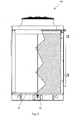
- the device 50 of the present invention may be used in a plant 100 for cooling, heating or humidifying fluids in the gaseous condition, such as the plant illustrated as example in Fig. 6 , with an operation corresponding to the description of Fig. 5 .
- the device 50 of the present invention may be used in a cooling plant 200 for articles in industrial processes, as shown in Fig. 7 .
- This plant is constituted by a structure 220 containing one or more articles 210 to be cooled and one or more evaporation plants 100 controlled, as a function of the industrial process, by one or more regulation systems integrated into one or more electric control and drive panels, installed inside or outside the cooling plant, in a local or remote position.
- the economizer device of the present invention is a sensor of presence of non evaporated water for regulation systems of evaporation plants integrated into cooling, heating or humidifying equipments having features responsive to measures against development, proliferation and ejection of harmful or lethal bacterial agents (the so-called anti-legionella regulations).
- the device of the present invention allows an immediate retroaction of the quantity of non evaporated water, a reduction of the operative costs, an undersizing of the water stock to be used for the evaporation plants, a reduction of costs for possible humidity probes, and finally a reduction of the risk of proliferation of noxious or lethal bacterial substances that may arise and develop because of excess water storage driven into the plants with circulation of forced air.
Landscapes
- Engineering & Computer Science (AREA)
- Chemical & Material Sciences (AREA)
- General Physics & Mathematics (AREA)
- Mechanical Engineering (AREA)
- General Engineering & Computer Science (AREA)
- Physics & Mathematics (AREA)
- Combustion & Propulsion (AREA)
- Automation & Control Theory (AREA)
- Chemical Kinetics & Catalysis (AREA)
- Electrochemistry (AREA)
- Fluid Mechanics (AREA)
- Life Sciences & Earth Sciences (AREA)
- Sustainable Development (AREA)
- Investigating Or Analyzing Materials By The Use Of Electric Means (AREA)
- Investigating Or Analyzing Materials Using Thermal Means (AREA)
Claims (11)
- Meldevorrichtung (50) des Durchflusses einer Flüssigkeit, enthaltend: einen nichtleitenden Hauptkörper (10) mit einem Kanal (12) für die durchflussende Flüssigkeit, der ein verengertes Teil (17) aufweist; der Hauptkörper (10) weiter enthält mindestens ein Paar Löcher (13, 15) auf den gegenüberliegenden Seiten des Kanals (12); diese Vorrichtung (50) weiter enthält zwei Elektroden (42, 44) und mindestens ein Paar leitende Elemente (30), die an entsprechenden gegenüberliegenden Seiten des verengerten Teils (17) und im Kanal so angeordnet sind, dass sich Durchgangslöcher (33, 35) in den besagten leitenden Elementen mit den Löchern (13, 15) des Hauptkörpers (10) aufreihen, und jedes leitende Element (30) eine Durchfluss (32) für die Flüssigkeit hat; diese Vorrichtung (50) ist dadurch gekennzeichnet, dass sie eine auch zum Erdboden senkrechte Mittelachse (X) aufweist und die Löcher (13, 15) an verschiedenen Höhen bezüglich der senkrechten Achse (X) der Vorrichtung (50) angeordnet sind, worin die Elektroden (42, 44) in die Löcher (13, 15) des Hauptkörpers (10) und in die Löcher (33, 35) der leitenden Elemente (30) so eingeführt werden, dass sie völlig in das Hauptkörper versenkt werden; und die leitenden Elemente (30 haben einen kegeligen Teil (36), der in einem zylindrischen runden Teil (34) zusammenlaüft, und jedes leitendes Element (30) mit einem gegenseitigen, nach der Stärke des verengerten Teils (17) bestimmten Abstand im Bereich von 5 mm - 15 mm angeordnet wird, um mindestens die Anwesenheit eines Niedrigwasserstands zu ermitteln, der durch die besagte senkrecht eingebaute Vorrichtung (50) fliesst und entlang dem kegeligen Teil (36) des oberen leitenden Elementes (30) wegen der Schwerkraft abwärts fliesst, so dass eine Beschleunigung entsteht und gestattet dem Niedrigwasserstand, den runden Teil (34) des unteren leitenden Elements (30) zu erreichen und einen elektrischen Durchgang zu erhalten, mit dem herrührenden Stromumlauf zwischen den beiden leitenden Elementen.
- Vorrichtung (50) nach Anspruch 1, worin die Vorrichtung (50) für den Gebrauch im Freien geeignet ist.
- Vorrichtung (50) nach Anspruch 1, worin die Elektroden (42, 44) an zum Erdboden verschiedenen Höhen angeordnet sind.
- Vorrichtung (50) nach Anspruch 1, worin die Elektroden (42, 44) angeschlossen und gesteuert werde, als ein Strom von Tropfen der Flüssigkeit im Elektrodenabstand vorhanden ist.
- Vorrichtung (50) nach Anspruch 1, worin die Elektroden (42, 44) nur von der innerhalb der Vorrichtung (50) durchfliessenden Flüssigkeit aktiviert werden.
- Vorrichtung (50) nach Anspruch 1, worin der Hauptkörper (10) aus einem Einzelteil bzw. aus mehreren Stücken besteht.
- Vorrichtung (50) nach Anspruch 1, worin die leitenden Elemente (30) im Durchflusskanal (12) des Hauptkörpers (10) an den gegenüberliegenden Seiten des verengerten Teils (17) mit Übermass angeordnet sind, und ihre kegeligen Teile (36) zum Einlass (14) bzw. Auslass (16) der Flüssigkeit im Kanal (12) gerichtet sind.
- Vorrichtung (50) nach Anspruch 1, worin der Hauptkörper (10) einen Ansatzflansch (11) weiter enthält und der Auslass mit einem Abflussrohr verbunden werden kann.
- Kühlsystem (100) für Flüssigkeiten, enthaltend einen Kreislauf (60) für die zu kühlende Flüssigkeit, worin der Kreislauf einen Pumpenstand (62), mindestens einen Wärmetauscher (64) und einen Kreislauf (70) für den Wärmeüberträger aufweist, wo der Kreislauf (70) einen Durchflussregler (72) für den Wärmeüberträger, der mindesten einen Flüssigkeitsabsorber (74) mit der Flüssigkeit versorgt, mindestens einen Sammlungsteil (75) für den Wärmeüberträger, ein Steuersystem für den Durchflussregler (72), ein Zirkulationssystem (80) für einen zweiten Wärmeüberträger enthält, worin der besagte zweite Wärmeüberträger den Flussigkeitsabsorber (74) und den Wärmetauscher (64) verbindet, dadurch gekennzeichnet, dass der Kühlsystem eine Meldevorrichtung (50) nach den vorhergehenden Ansprüchen weiter enthält, und der besagte Sammlungsteil (75) geeignet ist, um den Wärmeüberträger durch die besagte Meldevorrichtung (50) abzulassen, und das Steuersystem geeignet ist, um den Durchflussregler (72) auf der Grundlage von einem aus der Meldevorrichtung (50) erhaltenen Signal (I) zu steuern.
- System (100) nach Anspruch 9, worin dieses System verschiedene Dimensionen und Konfigurationen aufweisen kann.
- System (100) nach Anspruch 10, worin das System für Verdunstungsverflüssiger von Kühlanlagen, und der genannte Pumpenstand (62) durch eine Verdichtungsanlage ersetzt wird.
Applications Claiming Priority (2)
| Application Number | Priority Date | Filing Date | Title |
|---|---|---|---|
| IT000464A ITMI20120464A1 (it) | 2012-03-23 | 2012-03-23 | Economizzatore per sistemi di raffreddamento adiabatici |
| PCT/IB2013/000462 WO2013140233A2 (en) | 2012-03-23 | 2013-03-22 | Economizer for adiabatic cooling systems |
Publications (2)
| Publication Number | Publication Date |
|---|---|
| EP2828623A2 EP2828623A2 (de) | 2015-01-28 |
| EP2828623B1 true EP2828623B1 (de) | 2021-11-17 |
Family
ID=46582838
Family Applications (1)
| Application Number | Title | Priority Date | Filing Date |
|---|---|---|---|
| EP13720534.0A Active EP2828623B1 (de) | 2012-03-23 | 2013-03-22 | Vorwärmer für adiabatische kühlanlagen |
Country Status (3)
| Country | Link |
|---|---|
| EP (1) | EP2828623B1 (de) |
| IT (1) | ITMI20120464A1 (de) |
| WO (1) | WO2013140233A2 (de) |
Family Cites Families (8)
| Publication number | Priority date | Publication date | Assignee | Title |
|---|---|---|---|---|
| GB650199A (en) * | 1948-09-28 | 1951-02-14 | Londex Ltd | Improvements in or relating to milking equipment |
| US4994211A (en) * | 1989-09-05 | 1991-02-19 | Fuller Joe W | Water distribution apparatus for evaporative cooling system |
| US4986782A (en) * | 1989-11-24 | 1991-01-22 | Severtson Lyndon W | Liquid flow detector system |
| DE4110146A1 (de) * | 1991-03-27 | 1992-10-01 | Hoefelmayr Bio Melktech | Verfahren und vorrichtung zur messung eines der masse eines milchpfropfens entsprechenden wertes sowie des entsprechenden milchflusses |
| US5192464A (en) * | 1992-04-23 | 1993-03-09 | Lech Pawlowski | Evaporative cooler |
| NL1000471C1 (nl) * | 1995-03-24 | 1996-09-26 | Maasland Nv | Hoeveelheidsmeter en inrichting voor het melken van dieren, voorzien van een dergelijke meter. |
| NL1002600C2 (nl) * | 1996-03-13 | 1997-09-17 | Maasland Nv | Hoeveelheidsmeter en inrichting voor het melken van dieren, voorzien van een dergelijke meter. |
| JP2000300099A (ja) * | 1999-04-21 | 2000-10-31 | Orion Mach Co Ltd | 乳の流量検出装置 |
-
2012
- 2012-03-23 IT IT000464A patent/ITMI20120464A1/it unknown
-
2013
- 2013-03-22 EP EP13720534.0A patent/EP2828623B1/de active Active
- 2013-03-22 WO PCT/IB2013/000462 patent/WO2013140233A2/en not_active Ceased
Non-Patent Citations (1)
| Title |
|---|
| None * |
Also Published As
| Publication number | Publication date |
|---|---|
| WO2013140233A4 (en) | 2014-01-23 |
| WO2013140233A2 (en) | 2013-09-26 |
| EP2828623A2 (de) | 2015-01-28 |
| WO2013140233A3 (en) | 2013-11-28 |
| ITMI20120464A1 (it) | 2013-09-24 |
Similar Documents
| Publication | Publication Date | Title |
|---|---|---|
| US20210131684A1 (en) | Humidifier system | |
| US6622993B2 (en) | Humidifier including output efficiency and liquid level indicators | |
| EP1510767B1 (de) | Eiserzeugungsmaschine mit geringem Volumen | |
| US20050212152A1 (en) | System and method for humidifying homes and commercial sites | |
| KR101536284B1 (ko) | 히트펌프 시스템의 실외기 제상작업용 적상감지센서 | |
| EP3037738B1 (de) | Verfahren zum betrieb eines klimaanlagesystems vom freikühlungstyp für umgebungen und insbesondere rechenzentren | |
| US10113759B2 (en) | Air conditioner and control method thereof | |
| CN107741108B (zh) | 分液器及空调器 | |
| CN101506627B (zh) | 用于测量液体比重和高度的装置 | |
| CN111811039B (zh) | 空调系统及具有其的空调器 | |
| SE522778C2 (sv) | Behållare för uppsamling och utmatning av flis | |
| US20190203961A1 (en) | Method and Apparatus For Energy Saving and Efficient Air Conditioning and Heat Exchanging | |
| KR101369706B1 (ko) | 얼음 조각 제조 및 분배 장치 | |
| US5537096A (en) | Fire detecting device | |
| WO2013140233A2 (en) | Economizer for adiabatic cooling systems | |
| CN109984051B (zh) | 一种智能仓鼠笼 | |
| RU2319093C1 (ru) | Утилизатор тепла с кипящим слоем | |
| CN212618969U (zh) | 一种带检测监控的加湿器 | |
| CN108692492A (zh) | 降膜式蒸发器及空调 | |
| CN106247515A (zh) | 一种利用冷凝水加湿的自动调控加湿方法 | |
| CN211400091U (zh) | 空调室外机及具有其的空调系统 | |
| CN115138019A (zh) | 一种固体颗粒烟雾发生器 | |
| JP2017125648A (ja) | 冷却コンテナ | |
| US20250052462A1 (en) | Adiabatic cooler with control system for water and energy use reduction | |
| CN215637864U (zh) | 一种恒湿机滤网报警装置 |
Legal Events
| Date | Code | Title | Description |
|---|---|---|---|
| PUAI | Public reference made under article 153(3) epc to a published international application that has entered the european phase |
Free format text: ORIGINAL CODE: 0009012 |
|
| 17P | Request for examination filed |
Effective date: 20141020 |
|
| AK | Designated contracting states |
Kind code of ref document: A2 Designated state(s): AL AT BE BG CH CY CZ DE DK EE ES FI FR GB GR HR HU IE IS IT LI LT LU LV MC MK MT NL NO PL PT RO RS SE SI SK SM TR |
|
| AX | Request for extension of the european patent |
Extension state: BA ME |
|
| DAX | Request for extension of the european patent (deleted) | ||
| STAA | Information on the status of an ep patent application or granted ep patent |
Free format text: STATUS: EXAMINATION IS IN PROGRESS |
|
| 17Q | First examination report despatched |
Effective date: 20180612 |
|
| REG | Reference to a national code |
Ref country code: DE Ref legal event code: R079 Ref document number: 602013080079 Country of ref document: DE Free format text: PREVIOUS MAIN CLASS: G01F0001640000 Ipc: F24F0006040000 |
|
| GRAP | Despatch of communication of intention to grant a patent |
Free format text: ORIGINAL CODE: EPIDOSNIGR1 |
|
| STAA | Information on the status of an ep patent application or granted ep patent |
Free format text: STATUS: GRANT OF PATENT IS INTENDED |
|
| RIC1 | Information provided on ipc code assigned before grant |
Ipc: F24F 6/04 20060101AFI20210601BHEP Ipc: H01H 29/04 20060101ALI20210601BHEP Ipc: F24F 6/00 20060101ALI20210601BHEP Ipc: F24F 140/30 20180101ALI20210601BHEP Ipc: G01F 1/64 20060101ALI20210601BHEP Ipc: F24F 5/00 20060101ALI20210601BHEP Ipc: G05D 7/06 20060101ALI20210601BHEP |
|
| INTG | Intention to grant announced |
Effective date: 20210628 |
|
| GRAS | Grant fee paid |
Free format text: ORIGINAL CODE: EPIDOSNIGR3 |
|
| GRAA | (expected) grant |
Free format text: ORIGINAL CODE: 0009210 |
|
| STAA | Information on the status of an ep patent application or granted ep patent |
Free format text: STATUS: THE PATENT HAS BEEN GRANTED |
|
| AK | Designated contracting states |
Kind code of ref document: B1 Designated state(s): AL AT BE BG CH CY CZ DE DK EE ES FI FR GB GR HR HU IE IS IT LI LT LU LV MC MK MT NL NO PL PT RO RS SE SI SK SM TR |
|
| REG | Reference to a national code |
Ref country code: GB Ref legal event code: FG4D |
|
| REG | Reference to a national code |
Ref country code: IE Ref legal event code: FG4D |
|
| REG | Reference to a national code |
Ref country code: DE Ref legal event code: R096 Ref document number: 602013080079 Country of ref document: DE |
|
| REG | Reference to a national code |
Ref country code: AT Ref legal event code: REF Ref document number: 1448365 Country of ref document: AT Kind code of ref document: T Effective date: 20211215 |
|
| REG | Reference to a national code |
Ref country code: LT Ref legal event code: MG9D |
|
| REG | Reference to a national code |
Ref country code: NL Ref legal event code: MP Effective date: 20211117 |
|
| REG | Reference to a national code |
Ref country code: AT Ref legal event code: MK05 Ref document number: 1448365 Country of ref document: AT Kind code of ref document: T Effective date: 20211117 |
|
| PG25 | Lapsed in a contracting state [announced via postgrant information from national office to epo] |
Ref country code: RS Free format text: LAPSE BECAUSE OF FAILURE TO SUBMIT A TRANSLATION OF THE DESCRIPTION OR TO PAY THE FEE WITHIN THE PRESCRIBED TIME-LIMIT Effective date: 20211117 Ref country code: LT Free format text: LAPSE BECAUSE OF FAILURE TO SUBMIT A TRANSLATION OF THE DESCRIPTION OR TO PAY THE FEE WITHIN THE PRESCRIBED TIME-LIMIT Effective date: 20211117 Ref country code: FI Free format text: LAPSE BECAUSE OF FAILURE TO SUBMIT A TRANSLATION OF THE DESCRIPTION OR TO PAY THE FEE WITHIN THE PRESCRIBED TIME-LIMIT Effective date: 20211117 Ref country code: BG Free format text: LAPSE BECAUSE OF FAILURE TO SUBMIT A TRANSLATION OF THE DESCRIPTION OR TO PAY THE FEE WITHIN THE PRESCRIBED TIME-LIMIT Effective date: 20220217 Ref country code: AT Free format text: LAPSE BECAUSE OF FAILURE TO SUBMIT A TRANSLATION OF THE DESCRIPTION OR TO PAY THE FEE WITHIN THE PRESCRIBED TIME-LIMIT Effective date: 20211117 |
|
| PG25 | Lapsed in a contracting state [announced via postgrant information from national office to epo] |
Ref country code: IS Free format text: LAPSE BECAUSE OF FAILURE TO SUBMIT A TRANSLATION OF THE DESCRIPTION OR TO PAY THE FEE WITHIN THE PRESCRIBED TIME-LIMIT Effective date: 20220317 Ref country code: SE Free format text: LAPSE BECAUSE OF FAILURE TO SUBMIT A TRANSLATION OF THE DESCRIPTION OR TO PAY THE FEE WITHIN THE PRESCRIBED TIME-LIMIT Effective date: 20211117 Ref country code: PT Free format text: LAPSE BECAUSE OF FAILURE TO SUBMIT A TRANSLATION OF THE DESCRIPTION OR TO PAY THE FEE WITHIN THE PRESCRIBED TIME-LIMIT Effective date: 20220317 Ref country code: PL Free format text: LAPSE BECAUSE OF FAILURE TO SUBMIT A TRANSLATION OF THE DESCRIPTION OR TO PAY THE FEE WITHIN THE PRESCRIBED TIME-LIMIT Effective date: 20211117 Ref country code: NO Free format text: LAPSE BECAUSE OF FAILURE TO SUBMIT A TRANSLATION OF THE DESCRIPTION OR TO PAY THE FEE WITHIN THE PRESCRIBED TIME-LIMIT Effective date: 20220217 Ref country code: NL Free format text: LAPSE BECAUSE OF FAILURE TO SUBMIT A TRANSLATION OF THE DESCRIPTION OR TO PAY THE FEE WITHIN THE PRESCRIBED TIME-LIMIT Effective date: 20211117 Ref country code: LV Free format text: LAPSE BECAUSE OF FAILURE TO SUBMIT A TRANSLATION OF THE DESCRIPTION OR TO PAY THE FEE WITHIN THE PRESCRIBED TIME-LIMIT Effective date: 20211117 Ref country code: HR Free format text: LAPSE BECAUSE OF FAILURE TO SUBMIT A TRANSLATION OF THE DESCRIPTION OR TO PAY THE FEE WITHIN THE PRESCRIBED TIME-LIMIT Effective date: 20211117 Ref country code: GR Free format text: LAPSE BECAUSE OF FAILURE TO SUBMIT A TRANSLATION OF THE DESCRIPTION OR TO PAY THE FEE WITHIN THE PRESCRIBED TIME-LIMIT Effective date: 20220218 Ref country code: ES Free format text: LAPSE BECAUSE OF FAILURE TO SUBMIT A TRANSLATION OF THE DESCRIPTION OR TO PAY THE FEE WITHIN THE PRESCRIBED TIME-LIMIT Effective date: 20211117 |
|
| PG25 | Lapsed in a contracting state [announced via postgrant information from national office to epo] |
Ref country code: SM Free format text: LAPSE BECAUSE OF FAILURE TO SUBMIT A TRANSLATION OF THE DESCRIPTION OR TO PAY THE FEE WITHIN THE PRESCRIBED TIME-LIMIT Effective date: 20211117 Ref country code: SK Free format text: LAPSE BECAUSE OF FAILURE TO SUBMIT A TRANSLATION OF THE DESCRIPTION OR TO PAY THE FEE WITHIN THE PRESCRIBED TIME-LIMIT Effective date: 20211117 Ref country code: RO Free format text: LAPSE BECAUSE OF FAILURE TO SUBMIT A TRANSLATION OF THE DESCRIPTION OR TO PAY THE FEE WITHIN THE PRESCRIBED TIME-LIMIT Effective date: 20211117 Ref country code: EE Free format text: LAPSE BECAUSE OF FAILURE TO SUBMIT A TRANSLATION OF THE DESCRIPTION OR TO PAY THE FEE WITHIN THE PRESCRIBED TIME-LIMIT Effective date: 20211117 Ref country code: DK Free format text: LAPSE BECAUSE OF FAILURE TO SUBMIT A TRANSLATION OF THE DESCRIPTION OR TO PAY THE FEE WITHIN THE PRESCRIBED TIME-LIMIT Effective date: 20211117 Ref country code: CZ Free format text: LAPSE BECAUSE OF FAILURE TO SUBMIT A TRANSLATION OF THE DESCRIPTION OR TO PAY THE FEE WITHIN THE PRESCRIBED TIME-LIMIT Effective date: 20211117 |
|
| REG | Reference to a national code |
Ref country code: DE Ref legal event code: R097 Ref document number: 602013080079 Country of ref document: DE |
|
| PLBE | No opposition filed within time limit |
Free format text: ORIGINAL CODE: 0009261 |
|
| STAA | Information on the status of an ep patent application or granted ep patent |
Free format text: STATUS: NO OPPOSITION FILED WITHIN TIME LIMIT |
|
| 26N | No opposition filed |
Effective date: 20220818 |
|
| PG25 | Lapsed in a contracting state [announced via postgrant information from national office to epo] |
Ref country code: MC Free format text: LAPSE BECAUSE OF FAILURE TO SUBMIT A TRANSLATION OF THE DESCRIPTION OR TO PAY THE FEE WITHIN THE PRESCRIBED TIME-LIMIT Effective date: 20211117 Ref country code: AL Free format text: LAPSE BECAUSE OF FAILURE TO SUBMIT A TRANSLATION OF THE DESCRIPTION OR TO PAY THE FEE WITHIN THE PRESCRIBED TIME-LIMIT Effective date: 20211117 |
|
| PG25 | Lapsed in a contracting state [announced via postgrant information from national office to epo] |
Ref country code: SI Free format text: LAPSE BECAUSE OF FAILURE TO SUBMIT A TRANSLATION OF THE DESCRIPTION OR TO PAY THE FEE WITHIN THE PRESCRIBED TIME-LIMIT Effective date: 20211117 |
|
| PG25 | Lapsed in a contracting state [announced via postgrant information from national office to epo] |
Ref country code: LU Free format text: LAPSE BECAUSE OF NON-PAYMENT OF DUE FEES Effective date: 20220322 Ref country code: IE Free format text: LAPSE BECAUSE OF NON-PAYMENT OF DUE FEES Effective date: 20220322 |
|
| P01 | Opt-out of the competence of the unified patent court (upc) registered |
Effective date: 20230530 |
|
| PG25 | Lapsed in a contracting state [announced via postgrant information from national office to epo] |
Ref country code: HU Free format text: LAPSE BECAUSE OF FAILURE TO SUBMIT A TRANSLATION OF THE DESCRIPTION OR TO PAY THE FEE WITHIN THE PRESCRIBED TIME-LIMIT; INVALID AB INITIO Effective date: 20130322 |
|
| PG25 | Lapsed in a contracting state [announced via postgrant information from national office to epo] |
Ref country code: MK Free format text: LAPSE BECAUSE OF FAILURE TO SUBMIT A TRANSLATION OF THE DESCRIPTION OR TO PAY THE FEE WITHIN THE PRESCRIBED TIME-LIMIT Effective date: 20211117 Ref country code: CY Free format text: LAPSE BECAUSE OF FAILURE TO SUBMIT A TRANSLATION OF THE DESCRIPTION OR TO PAY THE FEE WITHIN THE PRESCRIBED TIME-LIMIT Effective date: 20211117 |
|
| PG25 | Lapsed in a contracting state [announced via postgrant information from national office to epo] |
Ref country code: MT Free format text: LAPSE BECAUSE OF FAILURE TO SUBMIT A TRANSLATION OF THE DESCRIPTION OR TO PAY THE FEE WITHIN THE PRESCRIBED TIME-LIMIT Effective date: 20211117 |
|
| PGFP | Annual fee paid to national office [announced via postgrant information from national office to epo] |
Ref country code: CH Payment date: 20250401 Year of fee payment: 13 |
|
| PG25 | Lapsed in a contracting state [announced via postgrant information from national office to epo] |
Ref country code: TR Free format text: LAPSE BECAUSE OF FAILURE TO SUBMIT A TRANSLATION OF THE DESCRIPTION OR TO PAY THE FEE WITHIN THE PRESCRIBED TIME-LIMIT Effective date: 20211117 |
|
| REG | Reference to a national code |
Ref country code: CH Ref legal event code: U11 Free format text: ST27 STATUS EVENT CODE: U-0-0-U10-U11 (AS PROVIDED BY THE NATIONAL OFFICE) Effective date: 20260401 |
|
| PGFP | Annual fee paid to national office [announced via postgrant information from national office to epo] |
Ref country code: GB Payment date: 20260309 Year of fee payment: 14 |
|
| PGFP | Annual fee paid to national office [announced via postgrant information from national office to epo] |
Ref country code: DE Payment date: 20260311 Year of fee payment: 14 |
|
| PGFP | Annual fee paid to national office [announced via postgrant information from national office to epo] |
Ref country code: BE Payment date: 20260323 Year of fee payment: 14 Ref country code: IT Payment date: 20260318 Year of fee payment: 14 |
|
| PGFP | Annual fee paid to national office [announced via postgrant information from national office to epo] |
Ref country code: FR Payment date: 20260305 Year of fee payment: 14 |