EP2829056B1 - Tragbare vorrichtung mit einem integrierten infrarotbildgebungsmodul - Google Patents
Tragbare vorrichtung mit einem integrierten infrarotbildgebungsmodul Download PDFInfo
- Publication number
- EP2829056B1 EP2829056B1 EP13770520.8A EP13770520A EP2829056B1 EP 2829056 B1 EP2829056 B1 EP 2829056B1 EP 13770520 A EP13770520 A EP 13770520A EP 2829056 B1 EP2829056 B1 EP 2829056B1
- Authority
- EP
- European Patent Office
- Prior art keywords
- shield
- user
- external environment
- infrared imaging
- imaging module
- Prior art date
- Legal status (The legal status is an assumption and is not a legal conclusion. Google has not performed a legal analysis and makes no representation as to the accuracy of the status listed.)
- Active
Links
Images






Classifications
-
- H—ELECTRICITY
- H04—ELECTRIC COMMUNICATION TECHNIQUE
- H04N—PICTORIAL COMMUNICATION, e.g. TELEVISION
- H04N7/00—Television systems
- H04N7/18—Closed-circuit television [CCTV] systems, i.e. systems in which the video signal is not broadcast
-
- G—PHYSICS
- G03—PHOTOGRAPHY; CINEMATOGRAPHY; ANALOGOUS TECHNIQUES USING WAVES OTHER THAN OPTICAL WAVES; ELECTROGRAPHY; HOLOGRAPHY
- G03B—APPARATUS OR ARRANGEMENTS FOR TAKING PHOTOGRAPHS OR FOR PROJECTING OR VIEWING THEM; APPARATUS OR ARRANGEMENTS EMPLOYING ANALOGOUS TECHNIQUES USING WAVES OTHER THAN OPTICAL WAVES; ACCESSORIES THEREFOR
- G03B21/00—Projectors or projection-type viewers; Accessories therefor
- G03B21/14—Details
-
- H—ELECTRICITY
- H04—ELECTRIC COMMUNICATION TECHNIQUE
- H04N—PICTORIAL COMMUNICATION, e.g. TELEVISION
- H04N23/00—Cameras or camera modules comprising electronic image sensors; Control thereof
- H04N23/20—Cameras or camera modules comprising electronic image sensors; Control thereof for generating image signals from infrared radiation only
- H04N23/23—Cameras or camera modules comprising electronic image sensors; Control thereof for generating image signals from infrared radiation only from thermal infrared radiation
-
- A—HUMAN NECESSITIES
- A61—MEDICAL OR VETERINARY SCIENCE; HYGIENE
- A61F—FILTERS IMPLANTABLE INTO BLOOD VESSELS; PROSTHESES; DEVICES PROVIDING PATENCY TO, OR PREVENTING COLLAPSING OF, TUBULAR STRUCTURES OF THE BODY, e.g. STENTS; ORTHOPAEDIC, NURSING OR CONTRACEPTIVE DEVICES; FOMENTATION; TREATMENT OR PROTECTION OF EYES OR EARS; BANDAGES, DRESSINGS OR ABSORBENT PADS; FIRST-AID KITS
- A61F9/00—Methods or devices for treatment of the eyes; Devices for putting in contact-lenses; Devices to correct squinting; Apparatus to guide the blind; Protective devices for the eyes, carried on the body or in the hand
- A61F9/04—Eye-masks ; Devices to be worn on the face, not intended for looking through; Eye-pads for sunbathing
- A61F9/06—Masks, shields or hoods for welders
-
- A—HUMAN NECESSITIES
- A62—LIFE-SAVING; FIRE-FIGHTING
- A62B—DEVICES, APPARATUS OR METHODS FOR LIFE-SAVING
- A62B18/00—Breathing masks or helmets, e.g. affording protection against chemical agents or for use at high altitudes or incorporating a pump or compressor for reducing the inhalation effort
- A62B18/02—Masks
-
- H—ELECTRICITY
- H04—ELECTRIC COMMUNICATION TECHNIQUE
- H04N—PICTORIAL COMMUNICATION, e.g. TELEVISION
- H04N23/00—Cameras or camera modules comprising electronic image sensors; Control thereof
- H04N23/20—Cameras or camera modules comprising electronic image sensors; Control thereof for generating image signals from infrared radiation only
-
- H—ELECTRICITY
- H04—ELECTRIC COMMUNICATION TECHNIQUE
- H04N—PICTORIAL COMMUNICATION, e.g. TELEVISION
- H04N23/00—Cameras or camera modules comprising electronic image sensors; Control thereof
- H04N23/80—Camera processing pipelines; Components thereof
-
- H—ELECTRICITY
- H04—ELECTRIC COMMUNICATION TECHNIQUE
- H04N—PICTORIAL COMMUNICATION, e.g. TELEVISION
- H04N9/00—Details of colour television systems
- H04N9/12—Picture reproducers
- H04N9/31—Projection devices for colour picture display, e.g. using electronic spatial light modulators [ESLM]
- H04N9/3179—Video signal processing therefor
-
- G—PHYSICS
- G08—SIGNALLING
- G08B—SIGNALLING SYSTEMS, e.g. PERSONAL CALLING SYSTEMS; ORDER TELEGRAPHS; ALARM SYSTEMS
- G08B21/00—Alarms responsive to a single specified undesired or abnormal condition and not otherwise provided for
- G08B21/02—Alarms for ensuring the safety of persons
- G08B21/12—Alarms for ensuring the safety of persons responsive to undesired emission of substances, e.g. pollution alarms
Definitions
- host device 102 may include a socket 104, a shutter 105, motion sensors 194, a processor 195, a memory 196, a display 197, and/or other components 198.
- Socket 104 may be configured to receive infrared imaging module 100 as identified by arrow 101.
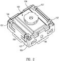
- Fig. 2 illustrates infrared imaging module 100 assembled in socket 104 in accordance with an example of the disclosure.
- infrared sensor assembly 128 may be electrically connected with processing module 160 through, for example, conductive electrical paths provided by: bond pads 142, complementary connections on inside surfaces of housing 120, electrical connections 126 of housing 120, connections 124, and circuit board 170.
- conductive electrical paths provided by: bond pads 142, complementary connections on inside surfaces of housing 120, electrical connections 126 of housing 120, connections 124, and circuit board 170.
- such an arrangement may be implemented without requiring wire bonds to be provided between infrared sensor assembly 128 and processing module 160.
- shutter 105 may be made from various materials such as, for example, polymers, glass, aluminum (e.g., painted or anodized) or other materials.
- shutter 105 may include one or more coatings to selectively filter electromagnetic radiation and/or adjust various optical properties of shutter 105 (e.g., a uniform blackbody coating or a reflective gold coating).
- a NUC process may be initiated by host device 102 if motion exceeding a threshold value is detected (e.g., motion greater than expected for ordinary use). It is contemplated that any desired type of spatial translation of host device 102 may be used to initiate the NUC process.
- a threshold value e.g., motion greater than expected for ordinary use. It is contemplated that any desired type of spatial translation of host device 102 may be used to initiate the NUC process.
- the accumulated image frames are averaged to provide a blurred image frame. Because the accumulated image frames were captured during motion, it is expected that actual scene information will vary between the image frames and thus cause the scene information to be further blurred in the resulting blurred image frame (block 545).
- FPN e.g., caused by one or more components of infrared imaging module 100
- FPN will remain fixed over at least short periods of time and over at least limited changes in scene irradiance during motion.
- image frames captured in close proximity in time and space during motion will suffer from identical or at least very similar FPN.
- scene information may change in consecutive image frames, the FPN will stay essentially constant.
- multiple image frames captured during motion will blur the scene information, but will not blur the FPN.
- FPN will remain more clearly defined in the blurred image frame provided in block 545 than the scene information.
- a defocus operation may be performed to intentionally defocus the image frames captured by infrared sensors 132.
- one or more actuators 199 may be used to adjust, move, or otherwise translate optical element 180, infrared sensor assembly 128, and/or other components of infrared imaging module 100 to cause infrared sensors 132 to capture a blurred (e.g., unfocused) image frame of the scene.
- Other non-actuator based techniques are also contemplated for intentionally defocusing infrared image frames such as, for example, manual (e.g., user-initiated) defocusing.
- FPN e.g., caused by one or more components of infrared imaging module 100
- FPN will remain unaffected by the defocusing operation.
- a blurred image frame of the scene will be provided (block 545) with FPN remaining more clearly defined in the blurred image than the scene information.
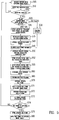
- the updated row and column FPN terms determined in block 550 are stored (block 552) and applied (block 555) to the blurred image frame provided in block 545. After these terms are applied, some of the spatial row and column FPN in the blurred image frame may be reduced. However, because such terms are applied generally to rows and columns, additional FPN may remain such as spatially uncorrelated FPN associated with pixel to pixel drift or other causes. Neighborhoods of spatially correlated FPN may also remain which may not be directly associated with individual rows and columns. Accordingly, further processing may be performed as discussed below to determine NUC terms.
- local contrast values e.g., edges or absolute values of gradients between adjacent or small groups of pixels
- scene information in the blurred image frame includes contrasting areas that have not been significantly blurred (e.g., high contrast edges in the original scene data)
- contrasting areas e.g., high contrast edges in the original scene data
- a flat field correction process is performed on the high pass filtered blurred image frame to determine updated NUC terms (e.g., if a NUC process has not previously been performed then the updated NUC terms may be new NUC terms in the first iteration of block 570).
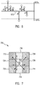
- Fig. 7 illustrates a flat field correction technique 700 in accordance with an example of the disclosure.
- a NUC term may be determined for each pixel 710 of the blurred image frame using the values of its neighboring pixels 712 to 726.
- several gradients may be determined based on the absolute difference between the values of various adjacent pixels. For example, absolute value differences may be determined between: pixels 712 and 714 (a left to right diagonal gradient), pixels 716 and 718 (a top to bottom vertical gradient), pixels 720 and 722 (a right to left diagonal gradient), and pixels 724 and 726 (a left to right horizontal gradient).
- the risk of introducing scene information into the NUC terms can be further reduced by applying some amount of temporal damping to the NUC term determination process.
- a temporal damping factor ⁇ between 0 and 1 may be chosen such that the new NUC term (NUC NEW ) stored is a weighted average of the old NUC term (NUC OLD ) and the estimated updated NUC term (NUC UPDATE ).
- NUC terms have been described with regard to gradients, local contrast values may be used instead where appropriate. Other techniques may also be used such as, for example, standard deviation calculations. Other types flat field correction processes may be performed to determine NUC terms including, for example, various processes identified in U.S. Patent No. 6,028,309 issued February 22, 2000 , U.S. Patent No. 6,812,465 issued November 2, 2004 , and U.S. Patent Application No. 12/114,865 filed May 5, 2008 .
- block 570 may include additional processing of the NUC terms.
- the sum of all NUC terms may be normalized to zero by subtracting the NUC term mean from each NUC term.
- the mean value of each row and column may be subtracted from the NUC terms for each row and column.
- row and column FPN filters using the row and column FPN terms determined in block 550 may be better able to filter out row and column noise in further iterations (e.g., as further shown in Fig. 8 ) after the NUC terms are applied to captured images (e.g., in block 580 further discussed herein).
- the row and column FPN filters may in general use more data to calculate the per row and per column offset coefficients (e.g., row and column FPN terms) and may thus provide a more robust alternative for reducing spatially correlated FPN than the NUC terms which are based on high pass filtering to capture spatially uncorrelated noise.
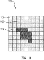
- additional high pass filtering and further determinations of updated NUC terms may be optionally performed to remove spatially correlated FPN such as exhibited by pixels 1110.
- the updated NUC terms determined in block 570 are applied to the blurred image frame.
- the blurred image frame will have been initially corrected for spatially correlated FPN (e.g., by application of the updated row and column FPN terms in block 555), and also initially corrected for spatially uncorrelated FPN (e.g., by application of the updated NUC terms applied in block 571).
- a further high pass filter is applied with a larger kernel than was used in block 565, and further updated NUC terms may be determined in block 573.
- the high pass filter applied in block 572 may include data from a sufficiently large enough neighborhood of pixels such that differences can be determined between unaffected pixels (e.g., pixels 1120) and affected pixels (e.g., pixels 1110).
- a low pass filter with a large kernel can be used (e.g., an N by N kernel that is much greater than 3 by 3 pixels) and the results may be subtracted to perform appropriate high pass filtering.
- blocks 571-573 may be repeated (e.g., cascaded) to iteratively perform high pass filtering with increasing kernel sizes to provide further updated NUC terms further correct for spatially correlated FPN of desired neighborhood sizes.
- the decision to perform such iterations may be determined by whether spatially correlated FPN has actually been removed by the updated NUC terms of the previous performance of blocks 571-573.
- thresholding criteria may be applied to individual pixels to determine which pixels receive updated NUC terms.
- the threshold values may correspond to differences between the newly calculated NUC terms and previously calculated NUC terms.
- the threshold values may be independent of previously calculated NUC terms.
- Other tests may be applied (e.g., spatial correlation tests) to determine whether the NUC terms should be applied.
- the flow diagram returns to block 505. Otherwise, the newly determined NUC terms are stored (block 575) to replace previous NUC terms (e.g., determined by a previously performed iteration of Fig. 5 ) and applied (block 580) to captured image frames.
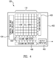
- such a high frame rate may be implemented, for example, by operating infrared sensor assembly 128 at relatively low voltages (e.g., compatible with mobile telephone voltages) and by using a relatively small array of infrared sensors 132 (e.g., an array of 64 by 64 infrared sensors in one example).
- relatively low voltages e.g., compatible with mobile telephone voltages
- infrared sensors 132 e.g., an array of 64 by 64 infrared sensors in one example.
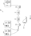
- Image frames 802 proceed through pipeline 800 where they are adjusted by various terms, temporally filtered, used to determine the various adjustment terms, and gain compensated.
- factory gain terms 812 and factory offset terms 816 are applied to image frames 802 to compensate for gain and offset differences, respectively, between the various infrared sensors 132 and/or other components of infrared imaging module 100 determined during manufacturing and testing.
- column FPN terms 820 and row FPN terms 824 are applied to image frames 802.
- Column FPN terms 820 and row FPN terms 824 may be determined in accordance with block 550 as discussed. In one example, if the column FPN terms 820 and row FPN terms 824 have not yet been determined (e.g., before a NUC process has been initiated), then blocks 818 and 822 may not be performed or initialization values may be used for the column FPN terms 820 and row FPN terms 824 that result in no alteration to the image data (e.g., offsets for every pixel would be equal to zero).
- the weight values determined in block 807 may be inversely proportional to averaged delta value 805c such that weight values drop rapidly towards zero when there are large differences between neighborhoods 803a and 803b.
- large differences between neighborhoods 803a and 803b may indicate that changes have occurred within the scene (e.g., due to motion) and pixels 802a and 802b may be appropriately weighted, in one example, to avoid introducing blur across frame-to-frame scene changes.
- Other associations between weight values and averaged delta value 805c may be used in various embodiments.
- pixel 805e of temporally filtered image frame 802e may be a weighted sum of pixels 805a and 805b of image frames 802a and 802b. If the average difference between pixels 805a and 805b is due to noise, then it may be expected that the average change between neighborhoods 805a and 805b will be close to zero (e.g., corresponding to the average of uncorrelated changes). Under such circumstances, it may be expected that the sum of the differences between neighborhoods 805a and 805b will be close to zero. In this case, pixel 805a of image frame 802a may both be appropriately weighted so as to contribute to the value of pixel 805e.
- averaged delta value 805c has been described as being determined based on neighborhoods 805a and 805b, in other examples averaged delta value 805c may be determined based on any desired criteria (e.g., based on individual pixels or other types of groups of sets of pixels).
- image frame 802a has been described as a presently received image frame and image frame 802b has been described as a previously temporally filtered image frame.
- image frames 802a and 802b may be first and second image frames captured by infrared imaging module 100 that have not been temporally filtered.
- Fig. 10 illustrates further implementation details in relation to the TNR process of block 826.
- image frames 802a and 802b may be read into line buffers 1010a and 1010b, respectively, and image frame 802b (e.g., the previous image frame) may be stored in a frame buffer 1020 before being read into line buffer 1010b.
- line buffers 1010a-b and frame buffer 1020 may be implemented by a block of random access memory (RAM) provided by any appropriate component of infrared imaging module 100 and/or host device 102.
- RAM random access memory
- image frame 802e may be passed to an automatic gain compensation block 828 for further processing to provide a result image frame 830 that may be used by host device 102 as desired.
- Fig. 8 further illustrates various operations that may be performed to determine row and column FPN terms and NUC terms as discussed.
- these operations may use image frames 802e as shown in Fig. 8 . Because image frames 802e have already been temporally filtered, at least some temporal noise may be removed and thus will not inadvertently affect the determination of row and column FPN terms 824 and 820 and NUC terms 817. In another example, non-temporally filtered image frames 802 may be used.
- row and column FPN terms 824 and 820 and NUC terms 817 may be determined and applied in an iterative fashion such that updated terms are determined using image frames 802 to which previous terms have already been applied. As a result, the overall process of Fig. 8 may repeatedly update and apply such terms to continuously reduce the noise in image frames 830 to be used by host device 102.
- blocks 525, 535, and 540 are shown as operating at the normal frame rate of image frames 802 received by pipeline 800.
- the determination made in block 525 is represented as a decision diamond used to determine whether a given image frame 802 has sufficiently changed such that it may be considered an image frame that will enhance the blur if added to other image frames and is therefore accumulated (block 535 is represented by an arrow in this example) and averaged (block 540).
- column FPN terms 820 (block 550) is shown as operating at an update rate that in this example is 1/32 of the sensor frame rate (e.g., normal frame rate) due to the averaging performed in block 540. Other update rates may be used in other embodiments. Although only column FPN terms 820 are identified in Fig. 10 , row FPN terms 824 may be implemented in a similar fashion at the reduced frame rate.
- Fig. 10 also illustrates further implementation details in relation to the NUC determination process of block 570.
- the blurred image frame may be read to a line buffer 1030 (e.g., implemented by a block of RAM provided by any appropriate component of infrared imaging module 100 and/or host device 102).
- the flat field correction technique 700 of Fig. 7 may be performed on the blurred image frame.
- FPN FPN
- techniques described herein may be used to remove various types of FPN (e.g., including very high amplitude FPN) such as spatially correlated row and column FPN and spatially uncorrelated FPN.
- the rate at which row and column FPN terms and/or NUC terms are updated can be inversely proportional to the estimated amount of blur in the blurred image frame and/or inversely proportional to the magnitude of local contrast values (e.g., determined in block 560).
- the described techniques may provide advantages over conventional shutter-based noise correction techniques.
- a shutter e.g., such as shutter 105
- Power and maximum voltage supplied to, or generated by, infrared imaging module 100 may also be reduced if a shutter does not need to be mechanically operated. Reliability will be improved by removing the shutter as a potential point of failure.
- a shutterless process also eliminates potential image interruption caused by the temporary blockage of the imaged scene by a shutter.
- noise correction may be performed on image frames that have irradiance levels similar to those of the actual scene desired to be imaged. This can improve the accuracy and effectiveness of noise correction terms determined in accordance with the various described techniques.
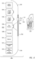
- Wearable apparatus 1200 may include a shield 1202, one or more infrared imaging modules 1204, a projector 1206, a processor 1208, a memory 1210, a communication module 1212, motion sensors 1214, and other components and hardware 1216.
- infrared imaging modules 1204, processor 1208, memory 1210, and motion sensors 1214 may be implemented in the same of similar manner as corresponding components of host device 102 of Fig. 1 .
- the various components of wearable apparatus 1200 may be configured to perform various NUC processes and other processes described herein.
- Shield 1202 protects at least a portion of a user's face from an external environment 1230 when wearable apparatus 1200 is worn by a user (e.g., generally identified by reference number 1203 in Fig. 12 ).
- Shield 1202 may be made of polymers (e.g., polycarbonate), metal, or any other appropriate materials durable enough to provide a protective barrier against heat, intensive light rays, debris, and/or other harmful elements from external environment 1230.
- Shield 1202 may comprise or may be coated with one or more appropriate protective layers to enhance or provide protection against such harmful elements.
- shield 1202 may provide a protective barrier against external environment 1230 for various components of wearable apparatus 1200 as well.
- infrared imaging modules 1204, projector 1206, processor 1208, memory 1210, communication module 1212, motion sensors 1214, and/or any appropriate components of wearable apparatus 1200 may be positioned internal to wearable apparatus 1200 (e.g., behind shield 1202 and away from external environment 1230), so that shield 1202 provides protection to these components in addition to protecting at least a portion of a user's face.
- shield 1202 is illustrated in Fig. 12 as having a limited length, shield 1202 may be implemented with any desired size.
- wearable apparatus 1200 may include one or more structural members 1201 to partially or completely enclose a face, head, or any desired portion of user 1203 (e.g., including the entirety of user 1203 if desired).
- shield 1202 may pass at least some visible light so that user 1203 can view external environment 1230 through shield 1202, while still being protected against harmful radiation (e.g., appropriate types of infrared radiation, ultraviolet radiation, and/or others), debris, and/or other elements.
- harmful radiation e.g., appropriate types of infrared radiation, ultraviolet radiation, and/or others
- a portion, a majority, or an entirety of shield 1202 may be opaque or nontransparent (e.g., when shield 1202 is made of metal).
- a surface of shield 1202 may comprise a plate onto which images may be projected from projector 1206.
- Infrared imaging modules 1204 may be small form factor infrared cameras or small form factor infrared imaging devices implemented in accordance with various embodiments disclosed herein. Infrared imaging modules 1204 may include an FPA implemented, for example, in accordance with various embodiments disclosed herein or others where appropriate.
- infrared imaging modules 1204 may be capable of detecting and capturing long wave infrared (LWIR) radiation, mid wave infrared (MWIR) radiation, and/or other radiation in thermal bands as may be desired.
- LWIR long wave infrared
- MWIR mid wave infrared
- infrared imaging modules 1204 may be configured to capture, process, and/or otherwise manage thermal images (e.g., images including thermal radiation data) of external environment 1230 even in complete darkness, and provide such images and data to processor 1208.
- thermal images provided by infrared imaging modules 1204 may reveal invisible hazards such as gas leaks, thermal hot spots, or others. Such thermal images may include an accurate temperature reading of each pixel in the images.
- thermal images captured and provided by infrared imaging modules 1204 are significantly more useful than images of amplified visible light and SWIR radiation that may be provided by conventional light intensifiers (e.g., night vision (NV) devices).
- NV night vision
- wearable apparatus 1200 may comprise a plurality of infrared imaging modules 1204 to capture stereoscopic thermal images of external environment 1230.
- one or more of a plurality of infrared imaging modules 1204 may provide fault tolerance by serving as backups to each other.
- infrared imaging modules 1204 and/or processor 1208 may be configured to provide automatic exposure control (e.g., by controlling signal gain, camera aperture, and/or shutter speed) to adjust to changes in the infrared intensity and temperature level of the external environment.
- automatic exposure control e.g., by controlling signal gain, camera aperture, and/or shutter speed
- one or more infrared imaging modules 1204 may be positioned behind shield 1202, so as to be protected from external environment 1230 by shield 1202.
- shield 1202 may include an aperture 1217 sealed with a window assembly 1218 capable of passing infrared rays 1232 through to infrared imaging module 1204.
- Window assembly 1218 may be made of a material (e.g., silicon or other material) having a high transmittance for infrared light, so that infrared light emitted from external environment 1230 reaches infrared imaging module 1204 while shield 1202 blocks infrared light from user 1203 and/or various components of wearable apparatus 1200.
- Processor 1208 may be implemented as any appropriate processing device as described with regard to processor 195 in Fig. 1 . In some embodiments, at least some part of processor 1208 may be implemented as part of infrared imaging modules 1204 and/or projector 1206.
- Processor 1208 may be configured to receive one or more thermal images captured by infrared imaging module 1204, and to process the thermal images to generate user-viewable thermal images (e.g., thermograms) of external environment 1230.
- processor 1208 may generate and overlay information and/or alarms (e.g., a temperature reading, a gas detection alarm, mask pressure reading and alarm, oxygen tank reading and alarm, and/or others) onto user-viewable images.
- processor 1208 may be configured to receive one or more thermal images from two or more infrared imaging modules 1204, and to appropriately combine the thermal images to generate stereoscopic user-viewable images (e.g., three dimensional thermograms) of external environment 1230 therefrom.
- Projector 1206 may be implemented with any appropriate small form factor projector, including those known as “pico” or “micro” projectors.
- projector 1206 may be sized small enough to be embedded inside personal electronic devices such as mobile phones or digital cameras.
- projector 1206 may be implemented in accordance with various technologies such as digital light processing (DLP), liquid crystal on silicon (LCoS), laser beam steering (LBS), holographic laser projection (HLP), and/or others as appropriate.
- DLP digital light processing
- LCDoS liquid crystal on silicon
- LBS laser beam steering
- HLP holographic laser projection
- Projector 1206 may be positioned so as to selectively project user-viewable thermal images onto an inner surface of shield 1202.
- projector 1206 can be turned on to project user-viewable thermal images onto a portion of an inner surface of shield 1202 that is comfortably within a line of sight of user 1203 while wearable apparatus 1200 is worn, and can be turned off when user 1203 desires a clear view through shield 1202.
- the direction of a beam from projector 1206 may be adjustable to project user-viewable thermal images onto an area of shield 1202 that is comfortable for viewing by a user, for example, for viewing images projected on shield 1202, and simultaneously viewing external environment 1230 through shield 1202.
- conventional fixed-type displays such as fixed LCD screens (e.g., viewed directly, through a scope or an objective lens), may obstruct a user's view even when not used, and may make it difficult for a user to adjust the screen's position or to simultaneously view visible light from external environment 1230 in realtime.
- projector 1206 may be configured to perform a distortion correction of user-viewable images projected on a surface of shield 1202, so that the user-viewable images appear flat and geometrically correct even when projected at an oblique angle and/or onto a curved surface of shield 1202.
- projector 1206 may optically correct distortion using optical elements such as lenses, prisms, and mirrors.
- distortion may be corrected through appropriate operations performed by projector 1206 and/or processor 1208.
- HLP technology may implement holographic processes to generate interference or diffraction patterns of an image instead of the image itself, and focused laser beams may be projected through such interference patterns to direct light as desired without relying on optical elements.
- projector 1206 may be configured to project two or more beams of light to present stereoscopic user-viewable images of external environment 1230 as described above. It is also contemplated that projector 1206 may be configured to project three dimensional user-viewable images using HLP technology.
- Communication module 1212 may be configured to handle internal communication between various components of wearable apparatus 1200.
- components such as infrared imaging modules 1204, projector 1206, and other sensors may transmit and receive data to and from processor 1208 through communication module 1212, which may manage wired and/or wireless connections (e.g., through proprietary RF links and/or through standard wireless communication protocols such as IEEE 802.11 WiFi standards and BluetoothTM) between the various components.
- wired and/or wireless connections e.g., through proprietary RF links and/or through standard wireless communication protocols such as IEEE 802.11 WiFi standards and BluetoothTM
- communication module 1212 may be further configured to handle communication with devices external to wearable apparatus 1200.
- communication module 1212 may transmit and receive user-viewable images generated by processor 1208 to and from other wearable apparatuses or a monitoring station so that user-viewable images can be shared with other users.
- communication module 1212 may handle a more conventional communication such as radio communication between users of wearable apparatus 1200.
- Other components and hardware 1216 may be used to implement any features of wearable apparatus 1200 as may be desired for various applications.
- other components may include various sensors, a microphone and speaker for voice communication, timers, a flashlight, and a visible light camera.
- Other hardware may include a mask frame, a hood, straps, fasteners, harnesses, connectors, hoses, and other various hardware and protective equipment and clothing as may be desired for certain applications of wearable apparatus 1200.
- Figs. 13A-C illustrate various views of wearable apparatus 1200 implemented as a self-contained breathing apparatus (SCBA) 1300, in accordance with embodiments of the disclosure.
- SCBA self-contained breathing apparatus
- Figs. 13A and 13B illustrate side and front views, respectively, of SCBA 1300 worn by user 1203 and having infrared imaging modules 1304 and a projector 1306 in accordance with embodiments of the disclosure.
- Fig. 13C illustrates a cross-sectional view of a window assembly 1318 of SCBA 1300, taken along line C-C' of Fig. 13B in accordance with an embodiment of the disclosure.
- SCBA 1300 may be implemented as a face mask for use by firefighters and/or other emergency personnel working in hazardous environments.
- SCBA 1300 may be implemented to attach to a portable air supply (e.g., one or more high-pressure air tanks) and may further include an inhalation connection (e.g., a mouthpiece or orinasal cover and a hose connector) to the air supply while protecting a wearer's face from hazardous environments.
- SCBA 1300 may be configured for underwater use as a self-contained underwater breathing apparatus (SCUBA).
- SCUBA self-contained underwater breathing apparatus
- SCBA 1300 may include a shield 1302, one or more infrared imaging modules 1304, projector 1306, a processor 1308, and a communication module 1312, all of which may be implemented in the same or similar manner as various corresponding components of wearable apparatus 1200 described above with regard to Fig. 12 .
- SCBA 1300 may further include a mask frame 1301 (e.g., corresponding to structural members 1201 of Fig. 12 ) onto which shield 1302 is sealingly fit.
- Mask frame 1301 may include an edge that compliantly engages the contours of the user's face, so that the user's face and SCBA 1300 form an interior space that is substantially sealed from an external environment.
- the interior space of SCBA 1300 may maintain a positive pressure (i.e., higher pressure inside SCBA 1300 than outside) so as to prevent inward leaking.
- Shield 1302 may be made of a clear polymer (e.g., polycarbonate) or other similar suitable materials that allow user 1203 to see through while providing a protective barrier against heat, flames, intense infrared and ultraviolet rays, debris, and/or other harmful elements from an external environment. Shield 1302 may comprise multiple layers of protective shields and/or surface coatings to enhance protection.
- a clear polymer e.g., polycarbonate
- Shield 1302 may comprise multiple layers of protective shields and/or surface coatings to enhance protection.
- One or more infrared imaging modules 1304 may be positioned behind shield 1302 or mask frame 1301, and internal to SCBA 1300.
- projector 1306, processor 1308, communication module 1312, and other components may be placed internal to SCBA 1300 (e.g., behind shield 1302 and behind or within mask frame 1301). It will be appreciated that these various components are thus advantageously protected by shield 1302 and mask frame 1301 of SCBA 1300 itself, without the need for separate protective external housings. It will also be appreciated that the small size and weight of infrared imaging modules 1304 advantageously permit these components to be positioned internal to SCBA 1300.
- one or more infrared imaging modules 1304 may be positioned on or attached to SCBA 1300 externally.
- Shield 1302 may include one or more apertures 1317 sealed by corresponding window assemblies 1318 capable of passing infrared radiation through to corresponding infrared imaging modules 1304 situated behind shield 1302, behind mask frame 1301, and/or within mask frame 1301.
- such a window assembly 1318 may include a window 1319 and a frame 1320.
- Window 1319 may be configured to pass infrared radiation.
- window 1319 may include silicon and/or other materials where appropriate to pass infrared radiation.
- Frame 1320 may be configured to hold window 1319 and seal aperture 1317 with window 1319.
- window assembly 1318 may be implemented by window 1319 alone without frame 1320.
- infrared imaging module 1304 may be configured to seal aperture 1317 to prevent user 1203 from being exposed to the external environment if the seal provided by the window assembly 1318 fails (e.g., to prevent inward leaking of gas, liquid, radiation, and/or other elements into the interior of SCBA 1300).
- SCBA 1300 advantageously allows user 1203 (e.g., firefighters, emergency personnel, divers, or anyone wearing SCBA 1300 for protection from an external environment) to comfortably view a user-viewable thermal image 1340 that helps user 1203 to recognize much more about an external environment (e.g., see through smoke, water or in darkness, discern victims or other objects, detect the base of fire, detect the temperature of objects, detect invisible gas leaks, or other phenomena) than what can be seen through the naked eye or through CCD-based or CMOS-based sensors, while also protecting the user's face and various components (e.g., protecting infrared imaging modules 1304, projector 1306, processor 1308 without a need for bulky and heavy external protective housings).
- an external environment e.g., see through smoke, water or in darkness, discern victims or other objects, detect the base of fire, detect the temperature of objects, detect invisible gas leaks, or other phenomena
- CCD-based or CMOS-based sensors while also protecting the user's face and various components (e.g., protecting
- Figs. 14A-B illustrate side views of wearable apparatus 1200 implemented as welding masks 1400 and 1401 in accordance with various embodiments of the disclosure.
- Welding masks 1400/1401 may be worn by user 1203 and may include a shield 1402, one or more infrared imaging modules 1404, a projector 1406, and a processor 1408, all of which may be implemented in the same or similar manner as various corresponding components of wearable apparatus 1200 and SCBA 1300 described above.
- projector 1406 is top mounted and shield 1402 has no user viewable opening.
- projector 1406 is bottom mounted and shield 1402 has a user viewable opening 1405.
- shield 1402 may include one or more apertures 1417 sealed with corresponding window assemblies 1418 implemented in the same or similar manner as window assemblies 1218/1318 described above, so as to pass infrared light through to corresponding infrared imaging modules 1404 that may be positioned internal to shield 1402.
- one or more infrared imaging modules 1404 may be mounted externally, for example on a top outside surface of shield 1402, as shown in Fig. 14A .
- Projector 1406 may be configured to project a user-viewable thermal image 1440 of a welding environment on a portion of a surface of shield 1402 that is comfortable for a user to view, as shown in Figs. 14A-B . It is to be understood that a surface of shield 1402 may also include a surface of viewing window 1405, if desired.
- User-viewable thermal image 1440 may help user 1203 better discern a welding scene, since user-viewable thermal images 1440 may be substantially clear of blindingly intense visible light radiation that are generated when welding.
- infrared imaging modules 1404 and/or processor 1408 may be configured to provide automatic exposure control, so as to generate user-viewable thermal images 1440 that are desirably adjusted to the infrared intensity and temperature level in the welding scene.
- Exposure-adjusted user-viewable thermal images 1440 may provide a clear view of the welding scene even when the infrared intensity and temperature level change (e.g., when user 1203 turns off a welding arc to adjust a welding tip of appropriate welding equipment), so that user 1203 can view the welding scene without having to lift, remove, and/or otherwise adjust welding mask 1400/1401 for a better view.
- processor 1408 may be configured to overlay temperature readings and/or temperature scales onto a user-viewable thermal image 1440 to be projected onto a surface of shield 1402. Such temperature readings and/or temperature scales may help a user to determine whether the temperature of a welding arc and/or welding pool is proper for a welding task.
- welding masks 1400/1401 advantageously protect a welder's face as well as various components of welding masks 1400/1401 from harsh elements of a welding environment, while also presenting to a welder a user-viewable thermal image 1440 that provides a clearer view of a welding environment along with useful information such as temperature readings of weld materials and a view of otherwise invisible objects (e.g., gas leaks).
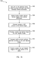
- Fig. 15 illustrates a process to present a user-viewable thermal image on wearable apparatus 1200, in accordance with an embodiment of the disclosure.
- the process of Fig. 15 may be applied generally to wearable apparatus 1200 and also to particular examples of wearable apparatus 1200 such as SCBA 1300, welding masks 1400/1401, and other applications where appropriate.
- user 1203 may put on wearable apparatus 1200 having shield 1202/1302/1402 that is configured to protect at least a portion of the user's face from external environment 1230.
- a firefighter may put on SCBA 1300 to protect the firefighter's face from a scene of fire
- a diver may put on SCBA 1300 when diving underwater
- a welder may put on welding mask 1400/1401 to protect the welder's face from a hazardous welding environment.
- one or more thermal images of external environment 1230 may be captured by one or more infrared imaging modules 1204/1304/1404.
- the one or more thermal images may be received, for example, at processor 1208/1308/1408 that is communicatively coupled via wired or wireless link to one or more infrared imaging modules 1204/1304/1404.
- a NUC process may be performed to remove noise from the thermal images, for example, by using various NUC techniques disclosed herein.
- user-viewable images may be generated by processor 1208/1308/1408 at block 1508.
- additional information and/or alarms may be overlaid onto the user-viewable images by processor 1208/1308/1408.
- processor 1208/1308/1408 is configured to receive one or more thermal images from two or more infrared imaging modules 1204/1304/1404, stereoscopic user-viewable images of external environment 1230 may be generated by processor 1208/1308/1408.
- a distortion correction may be performed on the user-viewable images by projector 1206/1306/1406 and/or processor 1208/1308/1408.
- projector 1206/1306/1406 may optically correct distortion of the user-viewable images to be projected onto a curved surface and/or projected at an oblique angle.
- projector 1206/1306/1406 and/or processor 1208/1308/1408 may correct such distortion computationally using appropriate holographic processes for projector 1206/1306/1406 based on interference/diffraction patterns.
- the corrected user-viewable images may be projected onto a surface of shield 1202/1302/1402 by projector 1206/1306/1406 for viewing by a user while wearing wearable apparatus 1200/SCBA 1300/welding mask 1400.
- the user-viewable images may be projected onto an area of shield 1202/1302/1402 that is comfortable for viewing by a user, for example, for simultaneously viewing projected images and an external environment through shield 1202/1302/1402.
- various embodiments provided by the present disclosure can be implemented using hardware, software, or combinations of hardware and software. Also where applicable, the various hardware components and/or software components set forth herein can be combined into composite components comprising software, hardware, and/or both without departing from the scope of the appended claims. Where applicable, the various hardware components and/or software components set forth herein can be separated into sub-components comprising software, hardware, or both without departing from the scope of the appended claims. In addition, where applicable, it is contemplated that software components can be implemented as hardware components, and vice-versa.
- Non-transitory instructions, program code, and/or data can be stored on one or more non-transitory machine readable mediums. It is also contemplated that software identified herein can be implemented using one or more general purpose or specific purpose computers and/or computer systems, networked and/or otherwise. Where applicable, the ordering of various steps described herein can be changed, combined into composite steps, and/or separated into sub-steps to provide features described herein.
Landscapes
- Engineering & Computer Science (AREA)
- Health & Medical Sciences (AREA)
- Multimedia (AREA)
- Signal Processing (AREA)
- Life Sciences & Earth Sciences (AREA)
- Toxicology (AREA)
- General Health & Medical Sciences (AREA)
- Public Health (AREA)
- Business, Economics & Management (AREA)
- Heart & Thoracic Surgery (AREA)
- Animal Behavior & Ethology (AREA)
- Biomedical Technology (AREA)
- Ophthalmology & Optometry (AREA)
- Veterinary Medicine (AREA)
- Zoology (AREA)
- Pulmonology (AREA)
- Vascular Medicine (AREA)
- Emergency Management (AREA)
- Physics & Mathematics (AREA)
- General Physics & Mathematics (AREA)
- Studio Devices (AREA)
- Transforming Light Signals Into Electric Signals (AREA)
- Photometry And Measurement Of Optical Pulse Characteristics (AREA)
- Radiation Pyrometers (AREA)
- Camera Bodies And Camera Details Or Accessories (AREA)
Claims (12)
- Tragbare Vorrichtung (1200), umfassend:eine Abschirmung (1202, 1302, 1402), die konfiguriert ist, um mindestens einen Abschnitt des Gesichts eines Benutzers vor einer äußeren Umgebung zu schützen;ein Infrarotbildgebungsmodul (1204, 1304, 1404), umfassend eine Brennebenenanordnung (FPA), die konfiguriert ist, um ein Wärmebild der äußeren Umgebung aufzunehmen;eine Apertur (1217, 1317, 1417) in der Abschirmung (1202, 1302, 1402);einen Scheibenaufbau (1218, 1318, 1418), der konfiguriert ist, um die Apertur (1217, 1317, 1417) abzudichten und Infrarotstrahlung von der äußeren Umgebung zu dem Infrarotbildgebungsmodul (1204, 1304, 1404) durchzulassen;einen Prozessor (1208, 1308, 1408), der konfiguriert ist, um das Wärmebild in ein vom Benutzer sichtbares Bild der äußeren Umgebung umzuwandeln; undeinen Projektor (1206, 1306, 1406), der konfiguriert ist, um das vom Benutzer sichtbare Bild auf eine innere Oberfläche der Abschirmung (1202, 1302, 1402) zu projizieren, für das Betrachten durch den Benutzer, während er die Vorrichtung (1200) trägt,wobei das Infrarotbildgebungsmodul (1204, 1304, 1404) und der Projektor (1206, 1306, 1406) innerhalb und hinter der Abschirmung (1202, 1302, 1402) positioniert ist, um das Infrarotbildgebungsmodul (1204, 1304, 1404) und den Projektor (1206, 1306, 1406) vor der äußeren Umgebung zu schützen.
- Vorrichtung (1200) gemäß Anspruch 1, wobei der Scheibenaufbau (1218, 1318, 1418) umfasst:eine Scheibe (1319), umfassend Silizium, und konfiguriert, die Infrarotstrahlung durchzulassen, undein Rahmen (1320), das konfiguriert ist, die Scheibe (1319) zu halten und die Apertur (1217, 1317, 1417) mit der Scheibe abzudichten; unddas Infrarotbildgebungsmodul (1204, 1304, 1404) ist konfiguriert, die Apertur (1217, 1317, 1417) abzudichten, um zu verhindern, dass der Benutzer der äußeren Umgebung ausgesetzt wird, wenn die durch den Scheibenaufbau (1218, 1318, 1418) bereitgestellte Abdichtung versagt.
- Vorrichtung (1200) gemäß Anspruch 1, wobei:die Vorrichtung (1200) eine unabhängige Atemvorrichtung (SCBA) ist, weiterhin umfassend einen Maskenrahmen (1301), der abdichtend mit der Abschirmung (1202, 1302, 1402) verbunden ist und konfiguriert ist, den Benutzer abdichtend zu erfassen; unddie Abschirmung (1202, 1302, 1402) konfiguriert ist, mindestens etwas sichtbares Licht von der äußeren Umgebung zum Benutzer durchzulassen, um die äußere Umgebung durch die Abschirmung (1202, 1302, 1402) zu betrachten.
- Vorrichtung (1200) gemäß Anspruch 1, wobei:die Vorrichtung (1200) eine Schweißmaske ist; undmindestens ein Großteil der Abschirmung (1202, 1302, 1402) im Wesentlichen lichtundurchlässig ist und konfiguriert ist, sichtbares Licht von der äußeren Umgebung im Wesentlichen zu blockieren.
- Vorrichtung (1200) gemäß Anspruch 1, wobei:das Infrarotbildgebungsmodul (1204, 1304, 1404) ein erstes Infrarotbildgebungsmodul ist;das Wärmebild ein erstes Wärmebild ist;die Vorrichtung (1200) weiterhin ein zweites Infrarotbildgebungsmodul umfasst, das konfiguriert ist, ein zweites Wärmebild der äußeren Umgebung aufzunehmen; unddas vom Benutzer sichtbare Bild ist ein räumliches Bild der äußeren Umgebung auf der Grundlage des ersten und des zweiten Wärmebildes.
- Vorrichtung (1200) gemäß Anspruch 1, wobei der Projektor (1206, 1306, 1406) ein holographischer Projektor ist.
- Verfahren (1500) zum Darstellen eines vom Benutzer sichtbaren Bildes auf einer tragbaren Vorrichtung (1200), wobei das Verfahren umfasst:Erhalten von Infrarotstrahlung von einer äußeren Umgebung durch eine Apertur in einer Abschirmung der tragbaren Vorrichtung und durch einen Scheibenaufbau, der konfiguriert wird, die Apertur abzudichten;Erfassen (1504) eines Wärmebildes von der äußeren Umgebung in einer Brennebenenanordnung (FPA) eines Infrarotbildgebungsmoduls der tragbaren Vorrichtung;Umwandeln (1508) des Wärmebildes in ein vom Benutzer sichtbares Bild der äußeren Umgebung;Projizieren (1512) des vom Benutzer sichtbaren Bildes durch einen Projektor auf eine innere Oberfläche der Abschirmung zum Betrachten durch einen Benutzer; undSchützen (1502) mindestens eines Abschnitts des Gesichts des Benutzers, des Infrarotbildgebungsmoduls und des Projektors vor der äußeren Umgebung durch die Abschirmung, wobei das Infrarotbildgebungsmodul und der Projektor innerhalb und hinter der Abschirmung positioniert werden, um durch die Abschirmung geschützt zu werden.
- Verfahren gemäß Anspruch 7, weiterhin umfassend Abdichten der Apertur durch das Infrarotbildgebungsmodul, um zu verhindern, dass der Benutzer der äußeren Umgebung ausgesetzt wird, wenn die durch den Scheibenaufbau bereitgestellte Abdichtung versagt, wobei der Scheibenaufbau umfasst:eine Scheibe, umfassend Silizium, und konfiguriert, die Infrarotstrahlung durchzulassen, undein Rahmen, der konfiguriert wird, die Scheibe zu halten und die Apertur mit der Scheibe abzudichten.
- Verfahren gemäß Anspruch 7, wobei die Vorrichtung eine unabhängige Atemvorrichtung (SCBA) ist, wobei das Verfahren weiterhin umfasst:abdichtendes Erfassen eines Maskenrahmens der Vorrichtung mit dem Benutzer, wobei der Maskenrahmen abdichtend mit der Abschirmung verbunden wird;Durchlassen mindestens etwas sichtbares Licht von der äußeren Umgebung durch die Abschirmung zum Benutzer, um die äußere Umgebung durch die Abschirmung zu betrachten.
- Verfahren gemäß Anspruch 7, wobei die Vorrichtung eine Schweißmaske ist und mindestens ein Großteil der Abschirmung ist im Wesentlichen lichtundurchlässig, wobei das Verfahren weiterhin im Wesentlichen Blockieren sichtbares Lichts von der äußeren Umgebung durch die Abschirmung umfasst.
- Verfahren gemäß Anspruch 7, wobei:das Infrarotbildgebungsmodul ein erstes Infrarotbildgebungsmodul ist;das Wärmebild ein erstes Wärmebild ist;das Verfahren weiterhin umfasst, Erfassen eines zweiten Wärmebildes von der äußeren Umgebung an einem zweiten Infrarotbildgebungsmodul der tragbaren Vorrichtung; unddas vom Benutzer sichtbare Bild ist ein räumliches Bild der äußeren Umgebung auf der Grundlage des ersten und des zweiten Wärmebildes.
- Verfahren zum Herstellen einer tragbaren Vorrichtung (1200), wobei das Verfahren umfasst:Bereitstellen einer Abschirmung (1202, 1302, 1402), um mindestens einen Abschnitt des Gesichts eines Benutzers vor einer äußeren Umgebung zu schützen;Bereitstellen einer Apertur (1217, 1317, 1417) in der Abschirmung;Positionieren eines Infrarotbildgebungsmoduls (1204, 1304, 1404) innerhalb und hinter der Abschirmung, um vor der äußeren Umgebung durch die Abschirmung geschützt zu werden ohne eine Notwendigkeit für separates äußeres Schutzgehäuse, wobei das Infrarotbildgebungsmodul eine Brennebenenanordnung (FPA) umfasst, die konfiguriert wird, ein Wärmebild der äußeren Umgebung aufzunehmen, während die Vorrichtung durch den Benutzer getragen wird;Abdichten der Apertur mit einem Scheibenaufbau (1218, 1318, 1418), der angepasst wird, Infrarotstrahlung von der äußeren Umgebung zu dem Infrarotbildgebungsmodul durchzulassen;Positionieren eines Projektors (1206, 1306, 1406) innerhalb und hinter der Abschirmung, um vor der äußeren Umgebung durch die Abschirmung geschützt zu werden, wobei der Projektor konfiguriert wird, ein vom Benutzer sichtbares Bild von der äußeren Umgebung auf eine innere Oberfläche der Abschirmung zu projizieren, um durch den Benutzer während Tragens der Vorrichtung betrachtet zu werden; undkommunizierendes Verbinden eines Prozessors (1208, 1308, 1408) mit dem Infrarotbildgebungsmodul und dem Projektor.
Applications Claiming Priority (7)
| Application Number | Priority Date | Filing Date | Title |
|---|---|---|---|
| US201261612794P | 2012-03-19 | 2012-03-19 | |
| US201261656889P | 2012-06-07 | 2012-06-07 | |
| PCT/US2012/041749 WO2012170949A2 (en) | 2011-06-10 | 2012-06-08 | Non-uniformity correction techniques for infrared imaging devices |
| PCT/US2012/041744 WO2012170946A2 (en) | 2011-06-10 | 2012-06-08 | Low power and small form factor infrared imaging |
| PCT/US2012/041739 WO2012170941A1 (en) | 2011-06-10 | 2012-06-08 | Infrared camera system architectures |
| US13/802,615 US9509924B2 (en) | 2011-06-10 | 2013-03-13 | Wearable apparatus with integrated infrared imaging module |
| PCT/US2013/031734 WO2013184220A2 (en) | 2012-03-19 | 2013-03-14 | Wearable apparatus with integrated infrared imaging module |
Publications (2)
| Publication Number | Publication Date |
|---|---|
| EP2829056A2 EP2829056A2 (de) | 2015-01-28 |
| EP2829056B1 true EP2829056B1 (de) | 2019-10-16 |
Family
ID=49712798
Family Applications (1)
| Application Number | Title | Priority Date | Filing Date |
|---|---|---|---|
| EP13770520.8A Active EP2829056B1 (de) | 2012-03-19 | 2013-03-14 | Tragbare vorrichtung mit einem integrierten infrarotbildgebungsmodul |
Country Status (5)
| Country | Link |
|---|---|
| EP (1) | EP2829056B1 (de) |
| KR (1) | KR101668544B1 (de) |
| CN (1) | CN204615945U (de) |
| CA (1) | CA2867895C (de) |
| WO (1) | WO2013184220A2 (de) |
Cited By (1)
| Publication number | Priority date | Publication date | Assignee | Title |
|---|---|---|---|---|
| US11346938B2 (en) | 2019-03-15 | 2022-05-31 | Msa Technology, Llc | Safety device for providing output to an individual associated with a hazardous environment |
Families Citing this family (10)
| Publication number | Priority date | Publication date | Assignee | Title |
|---|---|---|---|---|
| US10863163B2 (en) | 2015-09-16 | 2020-12-08 | Andrew Neil Aurigema | Vision enhancing system and method |
| US10682721B2 (en) | 2016-07-14 | 2020-06-16 | Lincoln Global, Inc. | Method and system for welding with temperature detector |
| US11438541B2 (en) | 2017-10-31 | 2022-09-06 | Sony Semiconductor Solutions Corporation | Imaging device with first temperature detection element and second temperature detection element for temperature reference |
| CA3086070C (en) | 2017-12-20 | 2021-02-09 | Adrien Birbaumer | Method of displaying an image on a see-through display |
| WO2020075043A1 (en) * | 2018-10-12 | 2020-04-16 | 3M Innovative Properties Company | Electronic personnel accountability report (epar) integration |
| KR102304919B1 (ko) * | 2019-09-24 | 2021-09-27 | 주식회사 오토스윙 | 용접 정보 제공 장치 |
| KR102125267B1 (ko) * | 2019-11-14 | 2020-06-23 | (주)토핀스 | 이동형 적외선 카메라장치 |
| KR102174417B1 (ko) * | 2019-12-03 | 2020-11-04 | 엘아이지넥스원 주식회사 | 영상 보정 시스템 및 영상 보정 방법 |
| KR102607980B1 (ko) * | 2021-11-01 | 2023-11-30 | 엘아이지넥스원 주식회사 | 오픈 루프 냉각 방식을 적용한 적외선 카메라의 영상검출장치 및 오픈 루프 냉각 방식을 적용한 적외선 카메라의 영상검출방법 |
| TWI826221B (zh) * | 2022-03-29 | 2023-12-11 | 宏達國際電子股份有限公司 | 頭戴式顯示裝置及眼球追蹤動作的控制方法 |
Citations (4)
| Publication number | Priority date | Publication date | Assignee | Title |
|---|---|---|---|---|
| US6072445A (en) * | 1990-12-31 | 2000-06-06 | Kopin Corporation | Head mounted color display system |
| US6384982B1 (en) * | 1996-10-08 | 2002-05-07 | The Microoptical Corporation | Compact image display system for eyeglasses or other head-borne frames |
| JP2006176931A (ja) * | 2004-12-22 | 2006-07-06 | Tanizawa Seisakusho Ltd | 撮影機能付きヘルメット |
| US20100088793A1 (en) * | 2006-06-06 | 2010-04-15 | Livio Ghisleni | Face and antiglare protection device for persons working in sites involving hazardous, damaging or disturbing radiation, especially welders |
Family Cites Families (15)
| Publication number | Priority date | Publication date | Assignee | Title |
|---|---|---|---|---|
| US4884137A (en) * | 1986-07-10 | 1989-11-28 | Varo, Inc. | Head mounted video display and remote camera system |
| US6023288A (en) * | 1993-03-31 | 2000-02-08 | Cairns & Brother Inc. | Combination head-protective helmet and thermal imaging apparatus |
| US6028309A (en) | 1997-02-11 | 2000-02-22 | Indigo Systems Corporation | Methods and circuitry for correcting temperature-induced errors in microbolometer focal plane array |
| EP1011424A1 (de) * | 1997-03-03 | 2000-06-28 | Schneider Medical Technologies, Inc. | Vorrichtung und verfahren zur bilderzeugung |
| US6812465B2 (en) | 2002-02-27 | 2004-11-02 | Indigo Systems Corporation | Microbolometer focal plane array methods and circuitry |
| US7034301B2 (en) | 2002-02-27 | 2006-04-25 | Indigo Systems Corporation | Microbolometer focal plane array systems and methods |
| DE10304703B4 (de) * | 2003-02-06 | 2023-03-16 | Bayerische Motoren Werke Aktiengesellschaft | Verfahren und Vorrichtung zur Sichtbarmachung der Umgebung eines Fahrzeugs mit umgebungsabhängiger Fusion eines Infrarot- und eines Visuell-Abbilds |
| JP2005010363A (ja) | 2003-06-18 | 2005-01-13 | Fuji Xerox Co Ltd | 画像形成装置 |
| KR100605455B1 (ko) * | 2004-04-27 | 2006-07-31 | 오토스테크 주식회사 | 카메라를 이용한 전자동 디지털 용접 헬멧 |
| JP4466569B2 (ja) | 2006-01-10 | 2010-05-26 | 株式会社豊田中央研究所 | カラー画像再生装置 |
| US7470902B1 (en) | 2006-03-20 | 2008-12-30 | Flir Systems, Inc. | Infrared camera electronic architectures |
| US7470904B1 (en) | 2006-03-20 | 2008-12-30 | Flir Systems, Inc. | Infrared camera packaging |
| CN101214178A (zh) * | 2007-12-26 | 2008-07-09 | 北京理工大学 | 视频增强现实辅助操作的焊接防护头盔 |
| US7679048B1 (en) | 2008-04-18 | 2010-03-16 | Flir Systems, Inc. | Systems and methods for selecting microbolometers within microbolometer focal plane arrays |
| KR101059748B1 (ko) * | 2009-01-06 | 2011-08-26 | 국방과학연구소 | 특징점 패턴을 이용한 헤드 트랙커에서 특징점 배치 방법 및 헬멧의 위치 추정 방법 |
-
2013
- 2013-03-14 EP EP13770520.8A patent/EP2829056B1/de active Active
- 2013-03-14 CA CA2867895A patent/CA2867895C/en active Active
- 2013-03-14 KR KR1020147028165A patent/KR101668544B1/ko active Active
- 2013-03-14 CN CN201390000509.5U patent/CN204615945U/zh not_active Expired - Lifetime
- 2013-03-14 WO PCT/US2013/031734 patent/WO2013184220A2/en not_active Ceased
Patent Citations (4)
| Publication number | Priority date | Publication date | Assignee | Title |
|---|---|---|---|---|
| US6072445A (en) * | 1990-12-31 | 2000-06-06 | Kopin Corporation | Head mounted color display system |
| US6384982B1 (en) * | 1996-10-08 | 2002-05-07 | The Microoptical Corporation | Compact image display system for eyeglasses or other head-borne frames |
| JP2006176931A (ja) * | 2004-12-22 | 2006-07-06 | Tanizawa Seisakusho Ltd | 撮影機能付きヘルメット |
| US20100088793A1 (en) * | 2006-06-06 | 2010-04-15 | Livio Ghisleni | Face and antiglare protection device for persons working in sites involving hazardous, damaging or disturbing radiation, especially welders |
Cited By (2)
| Publication number | Priority date | Publication date | Assignee | Title |
|---|---|---|---|---|
| US11346938B2 (en) | 2019-03-15 | 2022-05-31 | Msa Technology, Llc | Safety device for providing output to an individual associated with a hazardous environment |
| US12169234B2 (en) | 2019-03-15 | 2024-12-17 | Msa Technology, Llc | Safety device for providing output to an individual associated with a hazardous environment |
Also Published As
| Publication number | Publication date |
|---|---|
| KR101668544B1 (ko) | 2016-10-28 |
| KR20140134694A (ko) | 2014-11-24 |
| EP2829056A2 (de) | 2015-01-28 |
| CN204615945U (zh) | 2015-09-02 |
| WO2013184220A2 (en) | 2013-12-12 |
| CA2867895C (en) | 2018-03-06 |
| WO2013184220A3 (en) | 2014-08-21 |
| CA2867895A1 (en) | 2013-12-12 |
Similar Documents
| Publication | Publication Date | Title |
|---|---|---|
| US10250822B2 (en) | Wearable apparatus with integrated infrared imaging module | |
| CA2867895C (en) | Wearable apparatus with integrated infrared imaging module | |
| US11493765B2 (en) | Image relay systems and methods for wearable apparatuses | |
| US9973692B2 (en) | Situational awareness by compressed display of panoramic views | |
| US9807319B2 (en) | Wearable imaging devices, systems, and methods | |
| US9247131B2 (en) | Alignment of visible light sources based on thermal images | |
| CA2838992C (en) | Non-uniformity correction techniques for infrared imaging devices | |
| US10232237B2 (en) | Thermal-assisted golf rangefinder systems and methods | |
| US11445131B2 (en) | Imager with array of multiple infrared imaging modules | |
| US9377624B2 (en) | Reducing light damage in shutterless imaging devices according to future use | |
| US10321031B2 (en) | Device attachment with infrared imaging sensor | |
| US9986175B2 (en) | Device attachment with infrared imaging sensor | |
| US10169666B2 (en) | Image-assisted remote control vehicle systems and methods | |
| EP2719167B1 (de) | Infrarotabbildung mit geringem stromverbrauch und geringem formfaktor | |
| EP2923187B1 (de) | Hybride infrarotsensoranordnung mit heterogenen infrarotsensoren | |
| US9235023B2 (en) | Variable lens sleeve spacer | |
| US10079982B2 (en) | Determination of an absolute radiometric value using blocked infrared sensors | |
| WO2014105241A1 (en) | Device attachment with infrared imaging sensor | |
| CN103907342B (zh) | 利用阻隔红外传感器确定绝对辐射值的方法和装置 |
Legal Events
| Date | Code | Title | Description |
|---|---|---|---|
| PUAI | Public reference made under article 153(3) epc to a published international application that has entered the european phase |
Free format text: ORIGINAL CODE: 0009012 |
|
| 17P | Request for examination filed |
Effective date: 20140924 |
|
| AK | Designated contracting states |
Kind code of ref document: A2 Designated state(s): AL AT BE BG CH CY CZ DE DK EE ES FI FR GB GR HR HU IE IS IT LI LT LU LV MC MK MT NL NO PL PT RO RS SE SI SK SM TR |
|
| AX | Request for extension of the european patent |
Extension state: BA ME |
|
| DAX | Request for extension of the european patent (deleted) | ||
| STAA | Information on the status of an ep patent application or granted ep patent |
Free format text: STATUS: EXAMINATION IS IN PROGRESS |
|
| 17Q | First examination report despatched |
Effective date: 20180507 |
|
| REG | Reference to a national code |
Ref country code: DE Ref legal event code: R079 Ref document number: 602013061793 Country of ref document: DE Free format text: PREVIOUS MAIN CLASS: H04N0005330000 Ipc: G08B0021120000 |
|
| GRAP | Despatch of communication of intention to grant a patent |
Free format text: ORIGINAL CODE: EPIDOSNIGR1 |
|
| STAA | Information on the status of an ep patent application or granted ep patent |
Free format text: STATUS: GRANT OF PATENT IS INTENDED |
|
| RIC1 | Information provided on ipc code assigned before grant |
Ipc: H04N 5/33 20060101ALI20190515BHEP Ipc: H04N 7/18 20060101ALI20190515BHEP Ipc: G08B 21/12 20060101AFI20190515BHEP |
|
| INTG | Intention to grant announced |
Effective date: 20190607 |
|
| GRAS | Grant fee paid |
Free format text: ORIGINAL CODE: EPIDOSNIGR3 |
|
| GRAA | (expected) grant |
Free format text: ORIGINAL CODE: 0009210 |
|
| STAA | Information on the status of an ep patent application or granted ep patent |
Free format text: STATUS: THE PATENT HAS BEEN GRANTED |
|
| RIN1 | Information on inventor provided before grant (corrected) |
Inventor name: HOELTER, THEODORE R. Inventor name: LEPORE,GIOVANNI Inventor name: HOEGASTEN, NICHOLAS Inventor name: TERRE, WILLIAM A. Inventor name: STRANDEMAR, KATRIN Inventor name: TEICH, ANDREW C. |
|
| AK | Designated contracting states |
Kind code of ref document: B1 Designated state(s): AL AT BE BG CH CY CZ DE DK EE ES FI FR GB GR HR HU IE IS IT LI LT LU LV MC MK MT NL NO PL PT RO RS SE SI SK SM TR |
|
| RAP1 | Party data changed (applicant data changed or rights of an application transferred) |
Owner name: FLIR SYSTEMS, INC. |
|
| REG | Reference to a national code |
Ref country code: GB Ref legal event code: FG4D |
|
| REG | Reference to a national code |
Ref country code: CH Ref legal event code: EP |
|
| REG | Reference to a national code |
Ref country code: DE Ref legal event code: R096 Ref document number: 602013061793 Country of ref document: DE |
|
| REG | Reference to a national code |
Ref country code: IE Ref legal event code: FG4D |
|
| REG | Reference to a national code |
Ref country code: AT Ref legal event code: REF Ref document number: 1192045 Country of ref document: AT Kind code of ref document: T Effective date: 20191115 |
|
| REG | Reference to a national code |
Ref country code: NL Ref legal event code: MP Effective date: 20191016 |
|
| REG | Reference to a national code |
Ref country code: LT Ref legal event code: MG4D |
|
| REG | Reference to a national code |
Ref country code: AT Ref legal event code: MK05 Ref document number: 1192045 Country of ref document: AT Kind code of ref document: T Effective date: 20191016 |
|
| PG25 | Lapsed in a contracting state [announced via postgrant information from national office to epo] |
Ref country code: ES Free format text: LAPSE BECAUSE OF FAILURE TO SUBMIT A TRANSLATION OF THE DESCRIPTION OR TO PAY THE FEE WITHIN THE PRESCRIBED TIME-LIMIT Effective date: 20191016 Ref country code: LV Free format text: LAPSE BECAUSE OF FAILURE TO SUBMIT A TRANSLATION OF THE DESCRIPTION OR TO PAY THE FEE WITHIN THE PRESCRIBED TIME-LIMIT Effective date: 20191016 Ref country code: PT Free format text: LAPSE BECAUSE OF FAILURE TO SUBMIT A TRANSLATION OF THE DESCRIPTION OR TO PAY THE FEE WITHIN THE PRESCRIBED TIME-LIMIT Effective date: 20200217 Ref country code: SE Free format text: LAPSE BECAUSE OF FAILURE TO SUBMIT A TRANSLATION OF THE DESCRIPTION OR TO PAY THE FEE WITHIN THE PRESCRIBED TIME-LIMIT Effective date: 20191016 Ref country code: GR Free format text: LAPSE BECAUSE OF FAILURE TO SUBMIT A TRANSLATION OF THE DESCRIPTION OR TO PAY THE FEE WITHIN THE PRESCRIBED TIME-LIMIT Effective date: 20200117 Ref country code: NO Free format text: LAPSE BECAUSE OF FAILURE TO SUBMIT A TRANSLATION OF THE DESCRIPTION OR TO PAY THE FEE WITHIN THE PRESCRIBED TIME-LIMIT Effective date: 20200116 Ref country code: PL Free format text: LAPSE BECAUSE OF FAILURE TO SUBMIT A TRANSLATION OF THE DESCRIPTION OR TO PAY THE FEE WITHIN THE PRESCRIBED TIME-LIMIT Effective date: 20191016 Ref country code: BG Free format text: LAPSE BECAUSE OF FAILURE TO SUBMIT A TRANSLATION OF THE DESCRIPTION OR TO PAY THE FEE WITHIN THE PRESCRIBED TIME-LIMIT Effective date: 20200116 Ref country code: FI Free format text: LAPSE BECAUSE OF FAILURE TO SUBMIT A TRANSLATION OF THE DESCRIPTION OR TO PAY THE FEE WITHIN THE PRESCRIBED TIME-LIMIT Effective date: 20191016 Ref country code: LT Free format text: LAPSE BECAUSE OF FAILURE TO SUBMIT A TRANSLATION OF THE DESCRIPTION OR TO PAY THE FEE WITHIN THE PRESCRIBED TIME-LIMIT Effective date: 20191016 Ref country code: AT Free format text: LAPSE BECAUSE OF FAILURE TO SUBMIT A TRANSLATION OF THE DESCRIPTION OR TO PAY THE FEE WITHIN THE PRESCRIBED TIME-LIMIT Effective date: 20191016 Ref country code: NL Free format text: LAPSE BECAUSE OF FAILURE TO SUBMIT A TRANSLATION OF THE DESCRIPTION OR TO PAY THE FEE WITHIN THE PRESCRIBED TIME-LIMIT Effective date: 20191016 |
|
| PG25 | Lapsed in a contracting state [announced via postgrant information from national office to epo] |
Ref country code: IS Free format text: LAPSE BECAUSE OF FAILURE TO SUBMIT A TRANSLATION OF THE DESCRIPTION OR TO PAY THE FEE WITHIN THE PRESCRIBED TIME-LIMIT Effective date: 20200224 Ref country code: HR Free format text: LAPSE BECAUSE OF FAILURE TO SUBMIT A TRANSLATION OF THE DESCRIPTION OR TO PAY THE FEE WITHIN THE PRESCRIBED TIME-LIMIT Effective date: 20191016 Ref country code: RS Free format text: LAPSE BECAUSE OF FAILURE TO SUBMIT A TRANSLATION OF THE DESCRIPTION OR TO PAY THE FEE WITHIN THE PRESCRIBED TIME-LIMIT Effective date: 20191016 |
|
| PG25 | Lapsed in a contracting state [announced via postgrant information from national office to epo] |
Ref country code: AL Free format text: LAPSE BECAUSE OF FAILURE TO SUBMIT A TRANSLATION OF THE DESCRIPTION OR TO PAY THE FEE WITHIN THE PRESCRIBED TIME-LIMIT Effective date: 20191016 |
|
| REG | Reference to a national code |
Ref country code: DE Ref legal event code: R097 Ref document number: 602013061793 Country of ref document: DE |
|
| PG2D | Information on lapse in contracting state deleted |
Ref country code: IS |
|
| PG25 | Lapsed in a contracting state [announced via postgrant information from national office to epo] |
Ref country code: RO Free format text: LAPSE BECAUSE OF FAILURE TO SUBMIT A TRANSLATION OF THE DESCRIPTION OR TO PAY THE FEE WITHIN THE PRESCRIBED TIME-LIMIT Effective date: 20191016 Ref country code: DK Free format text: LAPSE BECAUSE OF FAILURE TO SUBMIT A TRANSLATION OF THE DESCRIPTION OR TO PAY THE FEE WITHIN THE PRESCRIBED TIME-LIMIT Effective date: 20191016 Ref country code: EE Free format text: LAPSE BECAUSE OF FAILURE TO SUBMIT A TRANSLATION OF THE DESCRIPTION OR TO PAY THE FEE WITHIN THE PRESCRIBED TIME-LIMIT Effective date: 20191016 Ref country code: CZ Free format text: LAPSE BECAUSE OF FAILURE TO SUBMIT A TRANSLATION OF THE DESCRIPTION OR TO PAY THE FEE WITHIN THE PRESCRIBED TIME-LIMIT Effective date: 20191016 Ref country code: IS Free format text: LAPSE BECAUSE OF FAILURE TO SUBMIT A TRANSLATION OF THE DESCRIPTION OR TO PAY THE FEE WITHIN THE PRESCRIBED TIME-LIMIT Effective date: 20200216 |
|
| PLBE | No opposition filed within time limit |
Free format text: ORIGINAL CODE: 0009261 |
|
| STAA | Information on the status of an ep patent application or granted ep patent |
Free format text: STATUS: NO OPPOSITION FILED WITHIN TIME LIMIT |
|
| PG25 | Lapsed in a contracting state [announced via postgrant information from national office to epo] |
Ref country code: IT Free format text: LAPSE BECAUSE OF FAILURE TO SUBMIT A TRANSLATION OF THE DESCRIPTION OR TO PAY THE FEE WITHIN THE PRESCRIBED TIME-LIMIT Effective date: 20191016 Ref country code: SM Free format text: LAPSE BECAUSE OF FAILURE TO SUBMIT A TRANSLATION OF THE DESCRIPTION OR TO PAY THE FEE WITHIN THE PRESCRIBED TIME-LIMIT Effective date: 20191016 Ref country code: SK Free format text: LAPSE BECAUSE OF FAILURE TO SUBMIT A TRANSLATION OF THE DESCRIPTION OR TO PAY THE FEE WITHIN THE PRESCRIBED TIME-LIMIT Effective date: 20191016 |
|
| 26N | No opposition filed |
Effective date: 20200717 |
|
| PG25 | Lapsed in a contracting state [announced via postgrant information from national office to epo] |
Ref country code: MC Free format text: LAPSE BECAUSE OF FAILURE TO SUBMIT A TRANSLATION OF THE DESCRIPTION OR TO PAY THE FEE WITHIN THE PRESCRIBED TIME-LIMIT Effective date: 20191016 |
|
| REG | Reference to a national code |
Ref country code: CH Ref legal event code: PL |
|
| PG25 | Lapsed in a contracting state [announced via postgrant information from national office to epo] |
Ref country code: SI Free format text: LAPSE BECAUSE OF FAILURE TO SUBMIT A TRANSLATION OF THE DESCRIPTION OR TO PAY THE FEE WITHIN THE PRESCRIBED TIME-LIMIT Effective date: 20191016 |
|
| REG | Reference to a national code |
Ref country code: BE Ref legal event code: MM Effective date: 20200331 |
|
| PG25 | Lapsed in a contracting state [announced via postgrant information from national office to epo] |
Ref country code: LU Free format text: LAPSE BECAUSE OF NON-PAYMENT OF DUE FEES Effective date: 20200314 |
|
| PG25 | Lapsed in a contracting state [announced via postgrant information from national office to epo] |
Ref country code: CH Free format text: LAPSE BECAUSE OF NON-PAYMENT OF DUE FEES Effective date: 20200331 Ref country code: LI Free format text: LAPSE BECAUSE OF NON-PAYMENT OF DUE FEES Effective date: 20200331 Ref country code: IE Free format text: LAPSE BECAUSE OF NON-PAYMENT OF DUE FEES Effective date: 20200314 |
|
| PG25 | Lapsed in a contracting state [announced via postgrant information from national office to epo] |
Ref country code: BE Free format text: LAPSE BECAUSE OF NON-PAYMENT OF DUE FEES Effective date: 20200331 |
|
| REG | Reference to a national code |
Ref country code: GB Ref legal event code: 732E Free format text: REGISTERED BETWEEN 20220224 AND 20220302 |
|
| PGFP | Annual fee paid to national office [announced via postgrant information from national office to epo] |
Ref country code: GB Payment date: 20220316 Year of fee payment: 10 |
|
| PG25 | Lapsed in a contracting state [announced via postgrant information from national office to epo] |
Ref country code: TR Free format text: LAPSE BECAUSE OF FAILURE TO SUBMIT A TRANSLATION OF THE DESCRIPTION OR TO PAY THE FEE WITHIN THE PRESCRIBED TIME-LIMIT Effective date: 20191016 Ref country code: MT Free format text: LAPSE BECAUSE OF FAILURE TO SUBMIT A TRANSLATION OF THE DESCRIPTION OR TO PAY THE FEE WITHIN THE PRESCRIBED TIME-LIMIT Effective date: 20191016 Ref country code: CY Free format text: LAPSE BECAUSE OF FAILURE TO SUBMIT A TRANSLATION OF THE DESCRIPTION OR TO PAY THE FEE WITHIN THE PRESCRIBED TIME-LIMIT Effective date: 20191016 |
|
| PG25 | Lapsed in a contracting state [announced via postgrant information from national office to epo] |
Ref country code: MK Free format text: LAPSE BECAUSE OF FAILURE TO SUBMIT A TRANSLATION OF THE DESCRIPTION OR TO PAY THE FEE WITHIN THE PRESCRIBED TIME-LIMIT Effective date: 20191016 |
|
| GBPC | Gb: european patent ceased through non-payment of renewal fee |
Effective date: 20230314 |
|
| PG25 | Lapsed in a contracting state [announced via postgrant information from national office to epo] |
Ref country code: GB Free format text: LAPSE BECAUSE OF NON-PAYMENT OF DUE FEES Effective date: 20230314 |
|
| PG25 | Lapsed in a contracting state [announced via postgrant information from national office to epo] |
Ref country code: GB Free format text: LAPSE BECAUSE OF NON-PAYMENT OF DUE FEES Effective date: 20230314 |
|
| PGFP | Annual fee paid to national office [announced via postgrant information from national office to epo] |
Ref country code: DE Payment date: 20260313 Year of fee payment: 14 |
|
| PGFP | Annual fee paid to national office [announced via postgrant information from national office to epo] |
Ref country code: FR Payment date: 20260330 Year of fee payment: 14 |