EP2829167B1 - Répartiteur pour un épandeur pneumatique - Google Patents
Répartiteur pour un épandeur pneumatique Download PDFInfo
- Publication number
- EP2829167B1 EP2829167B1 EP14401076.6A EP14401076A EP2829167B1 EP 2829167 B1 EP2829167 B1 EP 2829167B1 EP 14401076 A EP14401076 A EP 14401076A EP 2829167 B1 EP2829167 B1 EP 2829167B1
- Authority
- EP
- European Patent Office
- Prior art keywords
- distributor
- shut
- space
- slider
- distribution
- Prior art date
- Legal status (The legal status is an assumption and is not a legal conclusion. Google has not performed a legal analysis and makes no representation as to the accuracy of the status listed.)
- Active
Links
Images


Classifications
-
- A—HUMAN NECESSITIES
- A01—AGRICULTURE; FORESTRY; ANIMAL HUSBANDRY; HUNTING; TRAPPING; FISHING
- A01C—PLANTING; SOWING; FERTILISING
- A01C7/00—Sowing
- A01C7/08—Broadcast seeders; Seeders depositing seeds in rows
- A01C7/081—Seeders depositing seeds in rows using pneumatic means
- A01C7/084—Pneumatic distribution heads for seeders
Definitions
- the invention relates to a distributor for a pneumatic distributor according to the preamble of claim 1.
- Such a distributor is for example by the DE 102 10 010 B4 known.
- a gate valve is provided, which has the shape of a concentric to the annular space distributor cylinder section.
- This gate valve By means of this gate valve several inlet openings of distribution lines can be shut off at the same time, so that the working width is reduced in a simple manner.
- the side ends terminate at a considerable distance from the side walls of the distributor space. This is advantageous to the extent that a portion of the supplied air can escape via the distribution lines shut off from the distribution of material, so that a uniform distribution of the supplied material is maintained on the unrestricted distribution lines.
- the side ends terminate here directly in mounted on the side walls of the distribution space sliding guides. This in so far advantageous that the closed distribution lines are completely shut off and no material can get to the closed distribution lines. As a result of the fact that the air supplied to the blocked-off distribution lines does not want to be able to escape via the blocked distributor lines, the uniform distribution of the supplied material to the un-blocked distribution lines is disturbed.
- the invention has for its object to provide a simple remedy.
- the arrangement of the gate valve can be optimized in a simple manner.
- a particularly effective shielding of the blocked distribution lines, so that no possible material reaches the shut-off distribution lines is achieved in that the plate-shaped guide elements are arranged at an inserted into the distributor chamber gate valve in the direction of not closed off distributor space in a staggered manner before the side ends of the gate valve.
- An advantageous orientation of the guide elements is achieved in that the plate-shaped guide elements are arranged aligned at least approximately in the radial direction.
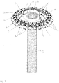
- the in the Fig. 1 to 3 illustrated distributor head 1 is part of a pneumatic metering and distribution system of a pneumatic working agricultural distributor.
- the research pipe 2 which is acted upon by a pneumatic conveying air flow, which is generated by a motor-driven fan, the redesignate material, such as seed or fertilizer is fed in an adjustable manner to the arranged at the end of the feed tube 2 header 1.
- the distributor head 1 the material is divided in a known manner to the leading to individual Ausbringorganen inlet openings 3 distribution lines 4.
- the distributor chamber 5 of the distributor head 1 is designed in a ring shape. From the distributor head 1, as already mentioned, several supply lines 4, which have inlet openings 3, lead away.
- the distributor head 1 is a gate valve 6, which is inserted from below into the distributor chamber 5 of the distributor head 1 assigned.
- This gate valve 6 is to be inserted into the distribution chamber 5 for shutting off, so that some inlet openings 3 of the distribution lines 4 can be shut off, and moved out of the distribution chamber 5, so that the supplied material is distributed to all inlet openings 3 of the distribution lines 4 in a uniform manner.
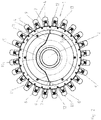
- the gate valve 6 is in its shut-off according to the Fig. 1 spaced from the inlet openings 3 of the distribution lines 4 and arranged to the side walls 7 of the distribution space 5, so that the air from the Supply line 2 to the inlet openings 3 of the shut-off distribution lines through the gap 8 between the side ends 9 of the gate valve 6 and the adjacent side walls 7 of the distributor head 1 passes, such as Fig. 1 and 2 demonstrate.
- the gate valve 6 has in the embodiment, as in Fig. 2 can be seen, the shape of a non-concentric to the annular distribution chamber 5 cylinder section.
- the gate valve has in its immediately adjacent to the supply line 2 a slide portion 10 which has a the circular contour of the supply line 2 and the annular distribution chamber 5 similar and / or adapted curve shape.
- At this central region 10 of the gate valve 6 close each on each side of an opposite curvature having slide portions 11 at. These sections 11 terminate in straight areas.
- the gate valve 6 has in its immediately adjacent to the supply line 2 an at least approximately annular cylinder portion 10 which extends over a range between 70 ° and 120 °, preferably about 90 °, and at least approximately concentric with the circular contour of the supply line 2 and annular distribution space runs.
- At this central region 10 of the gate valve 6 close to the center formed as a circle portion 10 each on each side of an opposite curvature having slide portions 11, which in the embodiment according to Fig. 2 leak into a straight area.
- the gate valve 6 thus has a wave-shaped contour course. Furthermore, this contour curve is such that it resembles the cross section of a deep-drawn soup plate with a plate edge.
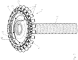
- the slider 6 can be pulled out by means not shown motor elements in an inoperative position of the distributor chamber 5, such as Fig. 3 shows that it does not interfere with the uniform distribution of seeds fed pneumatically via the supply line 2 to the distributor space 5, so that in the distributor space 5 the seed can be distributed in a uniform manner to the individual inlet openings 3 leading to the distributor lines 4.
- the plate-shaped guide elements 12 approaching the side walls 7 of the distributor chamber 5 are arranged in the region of the side ends 9 of the slide valve 6, like the Fig. 1 to 3 demonstrate.
- the arrangement is such that between the side ends 9 of the gate valve 6 and the free ends 13 of the plate-shaped guide elements 12, a gap-like distance 8 is present, as the Fig. 1 and 2 demonstrate.
- the plate-shaped guide elements 12 are arranged aligned at least approximately in the radial direction.
- the plate-shaped guide elements 12 are arranged at least approximately opposite one another.
- the plate-shaped guide elements 12 are arranged with inserted into the distributor chamber 5 gate valve 6 in the direction of the non-isolated distributor space in a staggered manner before the side ends 9 of the gate valve 6.
- the embodiment according to the 4 to 6 differs from the embodiment according to the Fig. 1 to 3 in that, in addition, a further gate valve 6, which is also located opposite the first gate valve 6 and can likewise be inserted into the distributor chamber 5 for shutting off distribution lines 4, is arranged in the distributor chamber 5.
- a further gate valve 6 which is also located opposite the first gate valve 6 and can likewise be inserted into the distributor chamber 5 for shutting off distribution lines 4, is arranged in the distributor chamber 5.
- Fig. 4 is the one in the Representation rear gate valve 6 is inserted into its shut-off position in the distribution chamber 5, while according to Fig. 6 the front gate valve 6 'in the representation is pushed into its shut-off position into the distributor chamber 5.
Landscapes
- Life Sciences & Earth Sciences (AREA)
- Soil Sciences (AREA)
- Environmental Sciences (AREA)
- Sliding Valves (AREA)
- Fertilizing (AREA)
Claims (4)
- Distributeur (1) pour une machine de distribution pneumatique de semences, d'engrais et similaires, comprenant les caractéristiques suivantes :1.1. une tête de distribution (1) définissant un espace de distribution annulaire (5),1.2. au moins une conduite d'alimentation (2) débouche dans la tête de distribution (1),1.3. à la tête de distribution (1) se raccordent, à distance de la conduite d'alimentation (2), des conduites de distribution (4),1.4. au moins une vanne d'arrêt (6, 6'),1.5. la vanne d'arrêt (6, 6) peut être introduite dans l'espace de distribution annulaire (5) et ressortie de celui-ci et ce de telle sorte que les extrémités latérales (9) de la vanne d'arrêt (6, 6'), dans sa position d'arrêt, soient disposées à distance des ouvertures d'entrée (3) des conduites de distribution (4) et/ou des parois latérales (7) de l'espace de distribution (5), de sorte que de l'air parvienne depuis la conduite d'alimentation (2) jusqu'aux ouvertures d'entrée (3) des conduites de distribution bloquées (4) à travers l'espace entre les extrémités latérales (9) de la vanne d'arrêt (6, 6') et la paroi latérale (7) adjacente de l'espace de distribution (5),
caractérisé en ce que
des éléments directeurs (12) en forme de plaque s'étendant jusqu'aux parois latérales (7) de l'espace de distribution (5) sont disposés dans la région des extrémités latérales (9) de la vanne d'arrêt (6, 6') enfoncée dans l'espace de distribution (5),
en ce qu'entre les extrémités latérales de la vanne d'arrêt (6, 6') enfoncée dans l'espace de distribution (5) et les extrémités libres (13) des éléments directeurs (12) en forme de plaque est prévu un espace de type fente (8) et en ce que la vanne d'arrêt (6, 6') peut être ressortie par rapport aux éléments directeurs (12) hors de l'espace de distribution (5) et peut être enfoncée dans celui-ci. - Distributeur selon la revendication 1, caractérisé en ce que lorsque la vanne d'arrêt (6, 6') est enfoncée dans l'espace de distribution (5), les éléments directeurs (12) en forme de plaque sont disposés de manière décalée avant les extrémités latérales (9) de la vanne d'arrêt (5) dans la direction de l'espace de distribution (5) non bloqué.
- Distributeur selon au moins l'une quelconque des revendications précédentes, caractérisé en ce que les éléments directeurs (12) en forme de plaque sont disposés de manière orientée au moins approximativement dans la direction radiale.
- Distributeur selon au moins l'une quelconque des revendications précédentes, caractérisé en ce que les éléments directeurs (12) en forme de plaque sont disposés au moins approximativement en regard les uns des autres.
Applications Claiming Priority (1)
| Application Number | Priority Date | Filing Date | Title |
|---|---|---|---|
| DE102013107943.1A DE102013107943A1 (de) | 2013-07-25 | 2013-07-25 | Verteiler für eine pneumatische Verteilmaschine |
Publications (2)
| Publication Number | Publication Date |
|---|---|
| EP2829167A1 EP2829167A1 (fr) | 2015-01-28 |
| EP2829167B1 true EP2829167B1 (fr) | 2017-04-26 |
Family
ID=51300681
Family Applications (1)
| Application Number | Title | Priority Date | Filing Date |
|---|---|---|---|
| EP14401076.6A Active EP2829167B1 (fr) | 2013-07-25 | 2014-07-22 | Répartiteur pour un épandeur pneumatique |
Country Status (2)
| Country | Link |
|---|---|
| EP (1) | EP2829167B1 (fr) |
| DE (1) | DE102013107943A1 (fr) |
Families Citing this family (3)
| Publication number | Priority date | Publication date | Assignee | Title |
|---|---|---|---|---|
| DE102015112249A1 (de) * | 2015-07-28 | 2017-02-02 | Amazonen-Werke H. Dreyer Gmbh & Co. Kg | Verteiler für eine pneumatische Verteilmaschine |
| DE102019128863B4 (de) * | 2019-10-25 | 2023-06-29 | Amazonen-Werke H. Dreyer SE & Co. KG | Verteilerkopf für eine pneumatisch arbeitende Verteilmaschine |
| DE102022120275A1 (de) | 2022-08-11 | 2024-02-22 | Amazonen-Werke H. Dreyer SE & Co. KG | Verteileinrichtung für eine landwirtschaftliche Ausbringmaschine und Verfahren zum Ausbringen von körnigem Material |
Family Cites Families (7)
| Publication number | Priority date | Publication date | Assignee | Title |
|---|---|---|---|---|
| DE29705999U1 (de) | 1997-04-03 | 1997-06-26 | Maschinenfabrik Rau GmbH, 73235 Weilheim | Vorrichtung zum Verteilen von partikelförmigem Gut |
| DE10210010C5 (de) | 2002-03-07 | 2010-02-04 | Kverneland Asa | Verteiler für eine Verteilmaschine |
| SE0302060L (sv) * | 2003-07-11 | 2004-12-21 | Vaederstad Verken Ab | Anordning vid fördelarhuvud |
| DE102007024464A1 (de) * | 2007-05-25 | 2008-11-27 | Alois Pöttinger Maschinenfabrik Gmbh | Verteilerkopf für eine Sä- oder Düngemaschine |
| DE102008009211A1 (de) * | 2008-02-15 | 2009-08-20 | Amazonen-Werke H. Dreyer Gmbh & Co. Kg | Verteiler für eine pneumatische Verteilmaschine |
| DE102009026333A1 (de) * | 2009-08-05 | 2011-02-10 | Amazonen-Werke H. Dreyer Gmbh & Co. Kg | Verteiler für eine Verteilmaschine |
| DE102010000629A1 (de) | 2010-03-04 | 2011-09-08 | Amazonen-Werke H. Dreyer Gmbh & Co. Kg | Verteiler für eine pneumatische Verteilmaschine |
-
2013
- 2013-07-25 DE DE102013107943.1A patent/DE102013107943A1/de not_active Withdrawn
-
2014
- 2014-07-22 EP EP14401076.6A patent/EP2829167B1/fr active Active
Non-Patent Citations (1)
| Title |
|---|
| None * |
Also Published As
| Publication number | Publication date |
|---|---|
| DE102013107943A1 (de) | 2015-01-29 |
| EP2829167A1 (fr) | 2015-01-28 |
Similar Documents
| Publication | Publication Date | Title |
|---|---|---|
| EP1164827B1 (fr) | Distributeur pneumatique | |
| EP3372065B1 (fr) | Tour de distribution d'une machine agricole, machine agricole et procédé de fonctionnement d'une telle machine agricole | |
| EP2578072B1 (fr) | Tête de répartiteur pour une machine à semence ou à engrais | |
| DE102017203855A1 (de) | Verteilerturm einer landwirtschaftlichen Maschine, landwirtschaftliche Maschine und Verfahren zum Betreiben einer solchen landwirtschaftlichen Maschine | |
| DE102007036661A1 (de) | Pneumatische Verteilmaschine | |
| EP2829167B1 (fr) | Répartiteur pour un épandeur pneumatique | |
| DE102016218531A1 (de) | Verteilturm einer landwirtschaftlichen Verteilmaschine | |
| EP2368415B1 (fr) | Semoir monograine pneumatique | |
| DE102013014386A1 (de) | Pneumatische Verteilmaschine | |
| EP2363015B1 (fr) | Distributeur pour machine de distribution pneumatique | |
| DE2755353B2 (de) | Verteilvorrichtung für Maschinen mit pneumatischer Ausbringung | |
| DE102009003791A1 (de) | Pneumatisch arbeitende Verteilmaschine | |
| DE102005038216A1 (de) | Verteilerkopf für eine pneumatische Sämaschine | |
| EP2298055A1 (fr) | Distributeur pour machine de distribution | |
| DE102017117923B3 (de) | Verteilerkopf für eine pneumatisch arbeitende Verteilmaschine | |
| DE102008009211A1 (de) | Verteiler für eine pneumatische Verteilmaschine | |
| DE2851797A1 (de) | Maschine zum ausstreuen von koernigem material | |
| DE102009026332A1 (de) | Verteiler für eine pneumatische Verteilmaschine | |
| EP2461662B1 (fr) | Tête de distribution | |
| EP3662731B1 (fr) | Machine pour l'épandage de solides granulaires avec un système de transport pneumatique | |
| EP3042556A1 (fr) | Semoir pneumatique | |
| DE202008004115U1 (de) | Pneumatische Verteileinrichtung einer landwirtschaftlichen Verteilmaschine | |
| DE102024123175A1 (de) | Verteiler für eine pneumatische Verteilmaschine | |
| DE102010036975A1 (de) | Pneumatisch arbeitende Verteilmaschine | |
| DE102013217628A1 (de) | Schienenfahrzeug mit Bremswiderstandsgehäuse |
Legal Events
| Date | Code | Title | Description |
|---|---|---|---|
| 17P | Request for examination filed |
Effective date: 20140722 |
|
| AK | Designated contracting states |
Kind code of ref document: A1 Designated state(s): AL AT BE BG CH CY CZ DE DK EE ES FI FR GB GR HR HU IE IS IT LI LT LU LV MC MK MT NL NO PL PT RO RS SE SI SK SM TR |
|
| AX | Request for extension of the european patent |
Extension state: BA ME |
|
| PUAI | Public reference made under article 153(3) epc to a published international application that has entered the european phase |
Free format text: ORIGINAL CODE: 0009012 |
|
| R17P | Request for examination filed (corrected) |
Effective date: 20150519 |
|
| RBV | Designated contracting states (corrected) |
Designated state(s): AL AT BE BG CH CY CZ DE DK EE ES FI FR GB GR HR HU IE IS IT LI LT LU LV MC MK MT NL NO PL PT RO RS SE SI SK SM TR |
|
| GRAP | Despatch of communication of intention to grant a patent |
Free format text: ORIGINAL CODE: EPIDOSNIGR1 |
|
| RIC1 | Information provided on ipc code assigned before grant |
Ipc: A01C 7/08 20060101AFI20170117BHEP |
|
| INTG | Intention to grant announced |
Effective date: 20170209 |
|
| GRAS | Grant fee paid |
Free format text: ORIGINAL CODE: EPIDOSNIGR3 |
|
| GRAA | (expected) grant |
Free format text: ORIGINAL CODE: 0009210 |
|
| AK | Designated contracting states |
Kind code of ref document: B1 Designated state(s): AL AT BE BG CH CY CZ DE DK EE ES FI FR GB GR HR HU IE IS IT LI LT LU LV MC MK MT NL NO PL PT RO RS SE SI SK SM TR |
|
| REG | Reference to a national code |
Ref country code: GB Ref legal event code: FG4D Free format text: NOT ENGLISH |
|
| REG | Reference to a national code |
Ref country code: CH Ref legal event code: EP |
|
| REG | Reference to a national code |
Ref country code: AT Ref legal event code: REF Ref document number: 887066 Country of ref document: AT Kind code of ref document: T Effective date: 20170515 |
|
| REG | Reference to a national code |
Ref country code: IE Ref legal event code: FG4D Free format text: LANGUAGE OF EP DOCUMENT: GERMAN |
|
| REG | Reference to a national code |
Ref country code: DE Ref legal event code: R096 Ref document number: 502014003548 Country of ref document: DE |
|
| REG | Reference to a national code |
Ref country code: FR Ref legal event code: PLFP Year of fee payment: 4 |
|
| REG | Reference to a national code |
Ref country code: SE Ref legal event code: TRGR |
|
| REG | Reference to a national code |
Ref country code: NL Ref legal event code: MP Effective date: 20170426 |
|
| REG | Reference to a national code |
Ref country code: LT Ref legal event code: MG4D |
|
| PG25 | Lapsed in a contracting state [announced via postgrant information from national office to epo] |
Ref country code: NL Free format text: LAPSE BECAUSE OF FAILURE TO SUBMIT A TRANSLATION OF THE DESCRIPTION OR TO PAY THE FEE WITHIN THE PRESCRIBED TIME-LIMIT Effective date: 20170426 |
|
| PG25 | Lapsed in a contracting state [announced via postgrant information from national office to epo] |
Ref country code: LT Free format text: LAPSE BECAUSE OF FAILURE TO SUBMIT A TRANSLATION OF THE DESCRIPTION OR TO PAY THE FEE WITHIN THE PRESCRIBED TIME-LIMIT Effective date: 20170426 Ref country code: GR Free format text: LAPSE BECAUSE OF FAILURE TO SUBMIT A TRANSLATION OF THE DESCRIPTION OR TO PAY THE FEE WITHIN THE PRESCRIBED TIME-LIMIT Effective date: 20170727 Ref country code: HR Free format text: LAPSE BECAUSE OF FAILURE TO SUBMIT A TRANSLATION OF THE DESCRIPTION OR TO PAY THE FEE WITHIN THE PRESCRIBED TIME-LIMIT Effective date: 20170426 Ref country code: ES Free format text: LAPSE BECAUSE OF FAILURE TO SUBMIT A TRANSLATION OF THE DESCRIPTION OR TO PAY THE FEE WITHIN THE PRESCRIBED TIME-LIMIT Effective date: 20170426 Ref country code: NO Free format text: LAPSE BECAUSE OF FAILURE TO SUBMIT A TRANSLATION OF THE DESCRIPTION OR TO PAY THE FEE WITHIN THE PRESCRIBED TIME-LIMIT Effective date: 20170726 Ref country code: FI Free format text: LAPSE BECAUSE OF FAILURE TO SUBMIT A TRANSLATION OF THE DESCRIPTION OR TO PAY THE FEE WITHIN THE PRESCRIBED TIME-LIMIT Effective date: 20170426 |
|
| PG25 | Lapsed in a contracting state [announced via postgrant information from national office to epo] |
Ref country code: IS Free format text: LAPSE BECAUSE OF FAILURE TO SUBMIT A TRANSLATION OF THE DESCRIPTION OR TO PAY THE FEE WITHIN THE PRESCRIBED TIME-LIMIT Effective date: 20170826 Ref country code: BG Free format text: LAPSE BECAUSE OF FAILURE TO SUBMIT A TRANSLATION OF THE DESCRIPTION OR TO PAY THE FEE WITHIN THE PRESCRIBED TIME-LIMIT Effective date: 20170726 Ref country code: LV Free format text: LAPSE BECAUSE OF FAILURE TO SUBMIT A TRANSLATION OF THE DESCRIPTION OR TO PAY THE FEE WITHIN THE PRESCRIBED TIME-LIMIT Effective date: 20170426 Ref country code: PL Free format text: LAPSE BECAUSE OF FAILURE TO SUBMIT A TRANSLATION OF THE DESCRIPTION OR TO PAY THE FEE WITHIN THE PRESCRIBED TIME-LIMIT Effective date: 20170426 Ref country code: RS Free format text: LAPSE BECAUSE OF FAILURE TO SUBMIT A TRANSLATION OF THE DESCRIPTION OR TO PAY THE FEE WITHIN THE PRESCRIBED TIME-LIMIT Effective date: 20170426 |
|
| REG | Reference to a national code |
Ref country code: DE Ref legal event code: R097 Ref document number: 502014003548 Country of ref document: DE |
|
| PG25 | Lapsed in a contracting state [announced via postgrant information from national office to epo] |
Ref country code: EE Free format text: LAPSE BECAUSE OF FAILURE TO SUBMIT A TRANSLATION OF THE DESCRIPTION OR TO PAY THE FEE WITHIN THE PRESCRIBED TIME-LIMIT Effective date: 20170426 Ref country code: CZ Free format text: LAPSE BECAUSE OF FAILURE TO SUBMIT A TRANSLATION OF THE DESCRIPTION OR TO PAY THE FEE WITHIN THE PRESCRIBED TIME-LIMIT Effective date: 20170426 Ref country code: SK Free format text: LAPSE BECAUSE OF FAILURE TO SUBMIT A TRANSLATION OF THE DESCRIPTION OR TO PAY THE FEE WITHIN THE PRESCRIBED TIME-LIMIT Effective date: 20170426 Ref country code: DK Free format text: LAPSE BECAUSE OF FAILURE TO SUBMIT A TRANSLATION OF THE DESCRIPTION OR TO PAY THE FEE WITHIN THE PRESCRIBED TIME-LIMIT Effective date: 20170426 Ref country code: RO Free format text: LAPSE BECAUSE OF FAILURE TO SUBMIT A TRANSLATION OF THE DESCRIPTION OR TO PAY THE FEE WITHIN THE PRESCRIBED TIME-LIMIT Effective date: 20170426 |
|
| PG25 | Lapsed in a contracting state [announced via postgrant information from national office to epo] |
Ref country code: IT Free format text: LAPSE BECAUSE OF FAILURE TO SUBMIT A TRANSLATION OF THE DESCRIPTION OR TO PAY THE FEE WITHIN THE PRESCRIBED TIME-LIMIT Effective date: 20170426 Ref country code: SM Free format text: LAPSE BECAUSE OF FAILURE TO SUBMIT A TRANSLATION OF THE DESCRIPTION OR TO PAY THE FEE WITHIN THE PRESCRIBED TIME-LIMIT Effective date: 20170426 |
|
| REG | Reference to a national code |
Ref country code: CH Ref legal event code: PL |
|
| PLBE | No opposition filed within time limit |
Free format text: ORIGINAL CODE: 0009261 |
|
| STAA | Information on the status of an ep patent application or granted ep patent |
Free format text: STATUS: NO OPPOSITION FILED WITHIN TIME LIMIT |
|
| 26N | No opposition filed |
Effective date: 20180129 |
|
| REG | Reference to a national code |
Ref country code: IE Ref legal event code: MM4A |
|
| PG25 | Lapsed in a contracting state [announced via postgrant information from national office to epo] |
Ref country code: IE Free format text: LAPSE BECAUSE OF NON-PAYMENT OF DUE FEES Effective date: 20170722 Ref country code: CH Free format text: LAPSE BECAUSE OF NON-PAYMENT OF DUE FEES Effective date: 20170731 Ref country code: LI Free format text: LAPSE BECAUSE OF NON-PAYMENT OF DUE FEES Effective date: 20170731 |
|
| PG25 | Lapsed in a contracting state [announced via postgrant information from national office to epo] |
Ref country code: SI Free format text: LAPSE BECAUSE OF FAILURE TO SUBMIT A TRANSLATION OF THE DESCRIPTION OR TO PAY THE FEE WITHIN THE PRESCRIBED TIME-LIMIT Effective date: 20170426 |
|
| REG | Reference to a national code |
Ref country code: FR Ref legal event code: PLFP Year of fee payment: 5 |
|
| REG | Reference to a national code |
Ref country code: BE Ref legal event code: MM Effective date: 20170731 |
|
| PG25 | Lapsed in a contracting state [announced via postgrant information from national office to epo] |
Ref country code: LU Free format text: LAPSE BECAUSE OF NON-PAYMENT OF DUE FEES Effective date: 20170722 |
|
| PG25 | Lapsed in a contracting state [announced via postgrant information from national office to epo] |
Ref country code: BE Free format text: LAPSE BECAUSE OF NON-PAYMENT OF DUE FEES Effective date: 20170731 |
|
| PG25 | Lapsed in a contracting state [announced via postgrant information from national office to epo] |
Ref country code: MT Free format text: LAPSE BECAUSE OF FAILURE TO SUBMIT A TRANSLATION OF THE DESCRIPTION OR TO PAY THE FEE WITHIN THE PRESCRIBED TIME-LIMIT Effective date: 20170426 |
|
| GBPC | Gb: european patent ceased through non-payment of renewal fee |
Effective date: 20180722 |
|
| PG25 | Lapsed in a contracting state [announced via postgrant information from national office to epo] |
Ref country code: GB Free format text: LAPSE BECAUSE OF NON-PAYMENT OF DUE FEES Effective date: 20180722 |
|
| PG25 | Lapsed in a contracting state [announced via postgrant information from national office to epo] |
Ref country code: MC Free format text: LAPSE BECAUSE OF FAILURE TO SUBMIT A TRANSLATION OF THE DESCRIPTION OR TO PAY THE FEE WITHIN THE PRESCRIBED TIME-LIMIT Effective date: 20170426 Ref country code: HU Free format text: LAPSE BECAUSE OF FAILURE TO SUBMIT A TRANSLATION OF THE DESCRIPTION OR TO PAY THE FEE WITHIN THE PRESCRIBED TIME-LIMIT; INVALID AB INITIO Effective date: 20140722 |
|
| PG25 | Lapsed in a contracting state [announced via postgrant information from national office to epo] |
Ref country code: CY Free format text: LAPSE BECAUSE OF FAILURE TO SUBMIT A TRANSLATION OF THE DESCRIPTION OR TO PAY THE FEE WITHIN THE PRESCRIBED TIME-LIMIT Effective date: 20170426 |
|
| PG25 | Lapsed in a contracting state [announced via postgrant information from national office to epo] |
Ref country code: MK Free format text: LAPSE BECAUSE OF FAILURE TO SUBMIT A TRANSLATION OF THE DESCRIPTION OR TO PAY THE FEE WITHIN THE PRESCRIBED TIME-LIMIT Effective date: 20170426 |
|
| PG25 | Lapsed in a contracting state [announced via postgrant information from national office to epo] |
Ref country code: TR Free format text: LAPSE BECAUSE OF FAILURE TO SUBMIT A TRANSLATION OF THE DESCRIPTION OR TO PAY THE FEE WITHIN THE PRESCRIBED TIME-LIMIT Effective date: 20170426 |
|
| PG25 | Lapsed in a contracting state [announced via postgrant information from national office to epo] |
Ref country code: PT Free format text: LAPSE BECAUSE OF FAILURE TO SUBMIT A TRANSLATION OF THE DESCRIPTION OR TO PAY THE FEE WITHIN THE PRESCRIBED TIME-LIMIT Effective date: 20170426 |
|
| PG25 | Lapsed in a contracting state [announced via postgrant information from national office to epo] |
Ref country code: AL Free format text: LAPSE BECAUSE OF FAILURE TO SUBMIT A TRANSLATION OF THE DESCRIPTION OR TO PAY THE FEE WITHIN THE PRESCRIBED TIME-LIMIT Effective date: 20170426 |
|
| REG | Reference to a national code |
Ref country code: DE Ref legal event code: R081 Ref document number: 502014003548 Country of ref document: DE Owner name: AMAZONEN-WERKE H. DREYER SE & CO. KG, DE Free format text: FORMER OWNER: AMAZONEN-WERKE H. DREYER GMBH & CO. KG, 49205 HASBERGEN, DE |
|
| PGFP | Annual fee paid to national office [announced via postgrant information from national office to epo] |
Ref country code: FR Payment date: 20210611 Year of fee payment: 8 |
|
| PGFP | Annual fee paid to national office [announced via postgrant information from national office to epo] |
Ref country code: SE Payment date: 20210712 Year of fee payment: 8 |
|
| REG | Reference to a national code |
Ref country code: SE Ref legal event code: EUG |
|
| PG25 | Lapsed in a contracting state [announced via postgrant information from national office to epo] |
Ref country code: SE Free format text: LAPSE BECAUSE OF NON-PAYMENT OF DUE FEES Effective date: 20220723 Ref country code: FR Free format text: LAPSE BECAUSE OF NON-PAYMENT OF DUE FEES Effective date: 20220731 |
|
| P01 | Opt-out of the competence of the unified patent court (upc) registered |
Effective date: 20230523 |
|
| PGFP | Annual fee paid to national office [announced via postgrant information from national office to epo] |
Ref country code: DE Payment date: 20250604 Year of fee payment: 12 |
|
| PGFP | Annual fee paid to national office [announced via postgrant information from national office to epo] |
Ref country code: AT Payment date: 20250625 Year of fee payment: 12 |