EP2829171A2 - Moissonneuse automotrice et véhicule associé - Google Patents
Moissonneuse automotrice et véhicule associé Download PDFInfo
- Publication number
- EP2829171A2 EP2829171A2 EP20140165657 EP14165657A EP2829171A2 EP 2829171 A2 EP2829171 A2 EP 2829171A2 EP 20140165657 EP20140165657 EP 20140165657 EP 14165657 A EP14165657 A EP 14165657A EP 2829171 A2 EP2829171 A2 EP 2829171A2
- Authority
- EP
- European Patent Office
- Prior art keywords
- transfer device
- transport vehicle
- control unit
- self
- vehicle
- Prior art date
- Legal status (The legal status is an assumption and is not a legal conclusion. Google has not performed a legal analysis and makes no representation as to the accuracy of the status listed.)
- Granted
Links
Images
Classifications
-
- A—HUMAN NECESSITIES
- A01—AGRICULTURE; FORESTRY; ANIMAL HUSBANDRY; HUNTING; TRAPPING; FISHING
- A01D—HARVESTING; MOWING
- A01D43/00—Mowers combined with apparatus performing additional operations while mowing
- A01D43/06—Mowers combined with apparatus performing additional operations while mowing with means for collecting, gathering or loading mown material
- A01D43/07—Mowers combined with apparatus performing additional operations while mowing with means for collecting, gathering or loading mown material in or into a trailer
- A01D43/073—Mowers combined with apparatus performing additional operations while mowing with means for collecting, gathering or loading mown material in or into a trailer with controllable discharge spout
Definitions
- the present invention relates to a self-propelled harvesting machine and a vehicle network in which the harvester cooperates coordinated with a transport vehicle.
- Forage harvesters of the forage harvester type are generally not designed to store significant quantities of crops on board; instead, the chopped crop is continuously over-loaded onto an adjacent moving transport vehicle.
- Harvesters of the type combine harvester usually have built-in harvest memory, so that they do not have to be constantly accompanied by a transport vehicle in harvesting, but it is also desirable here to be able to overload the contents of the crop storage while driving on a transport vehicle to in the for Overloading time does not have to interrupt the harvesting process.
- US2011 / 0318151A1 is a transport vehicle in which a transfer device in the manner of a conveyor belt from a cargo space of the transport vehicle can be swung out to the side.
- the transfer device of the harvesting vehicle and the transfer device of the transport vehicle together bridge the gap between the vehicles, the transfer device can be built shorter. Although this considerably reduces the moment of inertia of the transfer device and consequently also its mechanical load due to rocking movements, however, since the surface to which the crop has to impinge is considerably smaller at the transfer device than it is during direct transfer into the cargo space, the danger remains Harvested material misses its target and is lost, persisted or even reinforced.
- the object of the invention is to provide a self-propelled harvester or a vehicle composite with such a harvester, in which the risk of Erntegutrateen is reduced when overcharging.
- the object is achieved on the one hand, in which in a self-propelled harvester with at least one transfer device for conveying recorded and processed crop to a transport vehicle and a control unit for controlling the transfer device based on characteristic parameters of at least the transport vehicle these characteristic parameters the position of a transfer device of the transport vehicle comprise and controls the control unit based on the detected position of the transfer device, the position of the transfer device relative to the transfer device to keep a point of impact of the crop on the transfer device positioned.
- control unit may influence the speed of the harvesting machine and / or the transport vehicle.
- control unit for controlling the position of the transfer device relative to the transfer device can influence the orientation of the transfer device on the harvester.
- control unit When transferring to a transfer device rather than directly into the cargo hold of a transport vehicle, losses may also be incurred by crop being piling up on the transfer device and slipping sideways.
- the control unit records the Erntegut tosatz in the self-propelled harvester and outputs a representative of the Erntegut besatz control signal.
- Such a control signal can be used by the transport vehicle to control the speed of the transfer device.
- the invention also relates to a vehicle combination with a self-propelled harvester as described above and a transport vehicle.
- the transfer device is movable on the transport vehicle in such a composite. Since the control unit of the self-propelled harvester controls the position of the transfer device based on the detected position of the transfer device relative to the harvester, movements of the transfer device are automatically compensated relative to the transport vehicle, ie during transfer and transfer device practically not move against each other, a load compartment of Moving the vehicle to some extent under the transfer device, without this would have an impact on the Göladevorgang itself.
- the decision as to how the transfer device is to be positioned on the transport vehicle and which area of the cargo space it thus loads can be taken autonomously by a control unit of the transport vehicle.
- the control unit of the harvesting machine therefore need not know or take into account the geometry of the loading space, which facilitates the cooperation of the harvesting machine with different types of transport vehicles.
- the conveying direction of the transfer device is preferably oriented transversely to the direction of travel of the transport vehicle in order to allow overcharging while the harvesting machine and the transport vehicle travel side by side.
- the transfer device is expediently movable at least in the direction of travel of the transport vehicle.
- the control unit of the transport vehicle is preferably set up to control the position of the transfer device based on the distribution of the overburdened crop in the transport vehicle. Since the control unit of the transport vehicle only has to be able to work together with loading sensors of the same transport vehicle, a simply structured control unit suffices to avoid erroneous assessments of the loading condition and resulting disturbances of the transfer process.
- control unit of the transport vehicle can be set up, the control unit of the self-propelled harvesting machine to a planned movement of the transfer device to signal.
- control unit of the harvesting machine can start immediately with the start of the movement of the transfer device or even before with an appropriate control of the position of the transfer device and is not dependent on the position change of the transfer device is observable.
- the transfer device may in particular comprise a conveyor belt.
- the step a) is expediently carried out by a control unit of the transport vehicle, the steps b) and c), however, of a control unit of the self-propelled harvester.
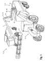
- Fig. 1 shows as an example of a vehicle assembly according to the invention in field use a combine harvester 1 as a self-propelled harvester 2 and a tractor 3 with trailer 4 as a transport vehicle 5.
- the lateral projection of a header 6 on the combine harvester 1 is greater than that of a combine mounted on the combine 1, here in one Matterlade ein swung-ejector 7.
- a transfer device 10 To the distance between an ejection end 8 of the discharge chute 7 and the trailer 4 across the The direction of travel of combine harvester 1 and tractor 3 to bridge, on a side wall of the trailer 4, a transfer device 10, here in the form of a conveyor belt 11, mounted.
- the transfer device 10 extends here transversely to the direction of travel of the combine harvester 1 and the tractor 3. For driving in traffic, it is displaceable in a position in which they completely and without overboard walls, over a bounded by the side walls loading area 12 of the trailer. 4 extends.
- the transfer device 10 in the longitudinal direction of the trailer 4 along the side of the combine harvester 1 facing side wall 13 is adjustable.
- the transfer device 10 may also be adjustable in length transversely to the direction of travel, for example, by the conveyor belt 11 as a whole is transverse to the side wall 13 adjustable, or in which the transfer device 10 is divided into a plurality of mutually movable sections.
- the discharge chute 7 is also adjustable. Its degrees of freedom include, in a manner known per se, rotation about a vertical axis passing through its base attached to the harvester 2, rotation about an axis extending horizontally through the base, and pivotal movement of a flap 15 at the discharge end 8.
- a camera 16 is mounted on the chute 7 and aligned to track the path of the ejected crop 14.
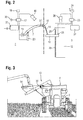
- the block diagram of Fig. 2 shows the camera 16, connected to a control unit 17 of the combine 1.
- the control unit 17 is further connected to a radio interface 18 to transmit and receive data. More of the control unit 17 outgoing control lines lead to an electric motor 19 which drives the rotation of the discharge elbow 7 about the vertical axis, and to actuators 20, 21 for pivoting the discharge elbow 7 about the horizontal axis or for pivoting the flap 15, and to an internal combustion engine 22, which drives the locomotion of the combine harvester 1.
- Fig. 2 On the right side of the Fig. 2 components of the transport vehicle 5 are shown. This also has a control unit 23, which is connected to a radio interface 24, with a sensor for assessing the Erntegutverannon on the bed 12 and motors 25, 26, 27.
- the sensor is in Fig. 2 shown as a second, arranged above the loading area 12 camera 28 shown whose images allow the control unit 23 to assess at which point of the bed 12, the crop is far away from the top edge of the side walls.
- the motor 25 drives the conveying movement of the conveyor belt 11.
- the motor 26 is used to adjust the transfer device 10 along the side wall 13, here for example by turning a threaded rod 29, which extends along the side wall 13 and on which an internal thread of the transfer device 10 engages.
- the motor 27 is the drive motor of the tractor 3.
- the camera 16 of the combine harvester 1 continuously monitors the flow of the over-loaded crop 14 and the position of the transfer device 10 relative to the flow of the crop 14.
- a deviation of the actual position from a target position is determined by the Detected control unit 17, and it is made a decision which of the various above-mentioned motors or actuators is driven to restore the desired position. Since the control of the position of the discharge chute 7 on the combine harvester 1 via the electric motor 19 and the actuator 20 is subject to a non-negligible game, a small deviation from the target position, as they are in particular due to slightly different speeds of combine 1 and transport vehicle. 5 may result, primarily by influencing the driving speed of one of these two vehicles corrected.
- control unit 17 can directly address the engine 22 of the combine harvester 1 or, via the radio interfaces 18, 24, the motor 27 of the tractor.
- the speed of the tractor 3 is controlled since a change in the speed of the combine 1 would also affect the crop throughput inside the combine and an adjustment of threshing unit parameters.
- the camera 28 continuously monitors the level of the crop on the bed 12. As long as the transfer device 10 is not moved along the side wall 13, it always unloads the crop on the bed 12 at the same location. If the control unit 23 recognizes from the images of the camera 28 that the filling level reaches a limit value at this point, it selects another point on the loading surface 12, at which there is still loading capacity.
- the control unit 23 then activates the motor 26 in order to move the transfer device 10 to the selected location.
- the resulting displacement of the transfer device 10 also relative to the flow of the crop 14 is detected by the camera 16 and causes the control unit 17 of the combine harvester 1 to track the position of the discharge chute 7.
- the displacement of the transfer device 10 along the side wall 13 can be significantly faster than the above-mentioned drifting of combine 1 and transport vehicle 5 against each other, for the correspondingly fast required tracking of the discharge chute 7, it may therefore be more appropriate to adjust the discharge chute 7 on the combine 1, instead of greatly changing the speed of combine 1 or transport vehicle 5.
- a control of the speed of combine harvester 1 or transport vehicle 5 preferably takes place only at the end of the adjustment process, when the transfer device 10 has come to a standstill on the ship's side 13 again and only fine corrections of the impact point of Erntegutstroms 14 on the transfer device 10 are needed, or if the freedom of movement of the discharge chute 7 on the combine harvester 1 by itself is not sufficient to the movement of the transfer device 10 to follow along the side wall 13.
- the control unit 23 when it has set a new position for the transfer device 10, the direction and preferably also the extent of the forthcoming movement of the transfer device 10 via the radio interfaces 24, 18 to the control unit 17.
- This allows synchronization of the Movements of the transfer device 10 and the ejection elbow 7. It must therefore not first come to a detectable by the camera 16 displacement of the transfer device 10 relative to the discharge chute 7 before the control unit 17 begins to track the position of the discharge chute 7; Even with high adjustment speed of the transfer device 10, the point of impact of the crop stream 14 on the transfer device 10 can be kept constant with good accuracy, and the risk of Erntegutleten overcharging is minimized.
- the combine harvester 1 has a grain tank in a customary manner, from which the crop to be loaded is fed to the discharge chute 7.
- the rate at which the grain is over-charged therefore, is largely arbitrary determinable and can during the entire overcharge process are kept constant. Consequently, the conveyor belt 11 can be driven by the motor 25 at a constant speed adapted to the load rate.
- Another type of harvester to which the present invention is applicable is a forage harvester. This generally has no intermediate storage for the crop, but the rate at which the crop is over-loaded at the chute 7 is the same with which it is picked up and processed by the forage harvester. The rate of overcharging is thus dependent on the density of the crop in the field and may vary during loading.
- control unit 17 may be connected to a sensor 30 for detecting the crop throughput and pass on its detection results via the radio interfaces 18, 24 to the control unit 23 of the transport vehicle 5. This then sets the speed of the motor 25 proportional to Erntegut besatz.
- the conveyor belt 11 runs faster, the higher the Erntegut malficient, the dumping height of the crop on the conveyor belt 11 can be limited so that no crop slips off the side of the conveyor belt 11 and is lost.
- Fig. 3 shows a combination of tractor 3 and trailer 4 with an alternative transfer device 10 in a front view.
- the transfer device 10 here has a tubular housing 30 in which a screw conveyor rotates.
- a funnel 31 is mounted to the from the chute 7th collected crop 14 and feed the screw conveyor.
- the hopper 31 makes the transfer operation insensitive to rocking movements of the discharge chute 7.
- the closed-walled housing 30 prevents losses of crop during transport from the hopper 31 to the loading space. Its diameter can be significantly smaller than the dimensions of the funnel 31.
Landscapes
- Life Sciences & Earth Sciences (AREA)
- Environmental Sciences (AREA)
- Guiding Agricultural Machines (AREA)
- Combines (AREA)
- Harvester Elements (AREA)
Applications Claiming Priority (1)
| Application Number | Priority Date | Filing Date | Title |
|---|---|---|---|
| DE201310012027 DE102013012027A1 (de) | 2013-07-19 | 2013-07-19 | Selbstfahrende Erntemaschine und Fahrzeugverbund |
Publications (3)
| Publication Number | Publication Date |
|---|---|
| EP2829171A2 true EP2829171A2 (fr) | 2015-01-28 |
| EP2829171A3 EP2829171A3 (fr) | 2015-05-27 |
| EP2829171B1 EP2829171B1 (fr) | 2018-06-20 |
Family
ID=50513169
Family Applications (1)
| Application Number | Title | Priority Date | Filing Date |
|---|---|---|---|
| EP14165657.9A Active EP2829171B1 (fr) | 2013-07-19 | 2014-04-23 | Moissonneuse automotrice et véhicule associé |
Country Status (3)
| Country | Link |
|---|---|
| EP (1) | EP2829171B1 (fr) |
| AU (1) | AU2014204446B2 (fr) |
| DE (1) | DE102013012027A1 (fr) |
Cited By (8)
| Publication number | Priority date | Publication date | Assignee | Title |
|---|---|---|---|---|
| EP3053428A1 (fr) * | 2015-02-05 | 2016-08-10 | CLAAS Selbstfahrende Erntemaschinen GmbH | Système de détermination du poids de remplissage d'un container de collecte mobile |
| EP3289852A1 (fr) * | 2016-08-29 | 2018-03-07 | CLAAS Selbstfahrende Erntemaschinen GmbH | Véhicule de transport |
| US12082531B2 (en) | 2022-01-26 | 2024-09-10 | Deere & Company | Systems and methods for predicting material dynamics |
| US12298767B2 (en) | 2022-04-08 | 2025-05-13 | Deere & Company | Predictive material consumption map and control |
| US12433194B2 (en) | 2022-08-11 | 2025-10-07 | Deere & Company | Systems and methods for predictive harvesting logistics |
| US12457929B2 (en) | 2022-08-11 | 2025-11-04 | Deere & Company | Systems and methods for predictive harvesting logistics |
| US12520759B2 (en) | 2022-01-26 | 2026-01-13 | Deere & Company | Systems and methods for predicting material dynamics |
| US12604791B2 (en) | 2022-07-06 | 2026-04-21 | Deere & Company | Machine control based upon estimated operator skill level trend |
Families Citing this family (55)
| Publication number | Priority date | Publication date | Assignee | Title |
|---|---|---|---|---|
| US11641800B2 (en) | 2020-02-06 | 2023-05-09 | Deere & Company | Agricultural harvesting machine with pre-emergence weed detection and mitigation system |
| US11240961B2 (en) | 2018-10-26 | 2022-02-08 | Deere & Company | Controlling a harvesting machine based on a geo-spatial representation indicating where the harvesting machine is likely to reach capacity |
| US11653588B2 (en) | 2018-10-26 | 2023-05-23 | Deere & Company | Yield map generation and control system |
| US11467605B2 (en) | 2019-04-10 | 2022-10-11 | Deere & Company | Zonal machine control |
| US11079725B2 (en) | 2019-04-10 | 2021-08-03 | Deere & Company | Machine control using real-time model |
| US11589509B2 (en) | 2018-10-26 | 2023-02-28 | Deere & Company | Predictive machine characteristic map generation and control system |
| US11672203B2 (en) | 2018-10-26 | 2023-06-13 | Deere & Company | Predictive map generation and control |
| US11957072B2 (en) | 2020-02-06 | 2024-04-16 | Deere & Company | Pre-emergence weed detection and mitigation system |
| US11178818B2 (en) | 2018-10-26 | 2021-11-23 | Deere & Company | Harvesting machine control system with fill level processing based on yield data |
| US12069978B2 (en) | 2018-10-26 | 2024-08-27 | Deere & Company | Predictive environmental characteristic map generation and control system |
| US11234366B2 (en) | 2019-04-10 | 2022-02-01 | Deere & Company | Image selection for machine control |
| US11778945B2 (en) | 2019-04-10 | 2023-10-10 | Deere & Company | Machine control using real-time model |
| US12225846B2 (en) | 2020-02-06 | 2025-02-18 | Deere & Company | Machine control using a predictive map |
| US12035648B2 (en) | 2020-02-06 | 2024-07-16 | Deere & Company | Predictive weed map generation and control system |
| US12329148B2 (en) | 2020-02-06 | 2025-06-17 | Deere & Company | Predictive weed map and material application machine control |
| US11477940B2 (en) | 2020-03-26 | 2022-10-25 | Deere & Company | Mobile work machine control based on zone parameter modification |
| US11927459B2 (en) | 2020-10-09 | 2024-03-12 | Deere & Company | Machine control using a predictive map |
| US11474523B2 (en) | 2020-10-09 | 2022-10-18 | Deere & Company | Machine control using a predictive speed map |
| US11635765B2 (en) | 2020-10-09 | 2023-04-25 | Deere & Company | Crop state map generation and control system |
| US12419220B2 (en) | 2020-10-09 | 2025-09-23 | Deere & Company | Predictive map generation and control system |
| US11844311B2 (en) | 2020-10-09 | 2023-12-19 | Deere & Company | Machine control using a predictive map |
| US11849672B2 (en) | 2020-10-09 | 2023-12-26 | Deere & Company | Machine control using a predictive map |
| US11592822B2 (en) | 2020-10-09 | 2023-02-28 | Deere & Company | Machine control using a predictive map |
| US11849671B2 (en) | 2020-10-09 | 2023-12-26 | Deere & Company | Crop state map generation and control system |
| US12550802B2 (en) | 2020-10-08 | 2026-02-17 | Deere & Company | Predictive machine characteristic map generation and control system |
| US11889788B2 (en) | 2020-10-09 | 2024-02-06 | Deere & Company | Predictive biomass map generation and control |
| US11983009B2 (en) | 2020-10-09 | 2024-05-14 | Deere & Company | Map generation and control system |
| US11864483B2 (en) | 2020-10-09 | 2024-01-09 | Deere & Company | Predictive map generation and control system |
| US12178158B2 (en) | 2020-10-09 | 2024-12-31 | Deere & Company | Predictive map generation and control system for an agricultural work machine |
| US11845449B2 (en) | 2020-10-09 | 2023-12-19 | Deere & Company | Map generation and control system |
| US12013245B2 (en) | 2020-10-09 | 2024-06-18 | Deere & Company | Predictive map generation and control system |
| US11675354B2 (en) | 2020-10-09 | 2023-06-13 | Deere & Company | Machine control using a predictive map |
| US11711995B2 (en) | 2020-10-09 | 2023-08-01 | Deere & Company | Machine control using a predictive map |
| US11874669B2 (en) | 2020-10-09 | 2024-01-16 | Deere & Company | Map generation and control system |
| US12386354B2 (en) | 2020-10-09 | 2025-08-12 | Deere & Company | Predictive power map generation and control system |
| US11650587B2 (en) | 2020-10-09 | 2023-05-16 | Deere & Company | Predictive power map generation and control system |
| US11871697B2 (en) | 2020-10-09 | 2024-01-16 | Deere & Company | Crop moisture map generation and control system |
| US11895948B2 (en) | 2020-10-09 | 2024-02-13 | Deere & Company | Predictive map generation and control based on soil properties |
| US12069986B2 (en) | 2020-10-09 | 2024-08-27 | Deere & Company | Map generation and control system |
| US11946747B2 (en) | 2020-10-09 | 2024-04-02 | Deere & Company | Crop constituent map generation and control system |
| US11825768B2 (en) | 2020-10-09 | 2023-11-28 | Deere & Company | Machine control using a predictive map |
| US12422847B2 (en) | 2020-10-09 | 2025-09-23 | Deere & Company | Predictive agricultural model and map generation |
| US11727680B2 (en) | 2020-10-09 | 2023-08-15 | Deere & Company | Predictive map generation based on seeding characteristics and control |
| US12250905B2 (en) | 2020-10-09 | 2025-03-18 | Deere & Company | Machine control using a predictive map |
| US11889787B2 (en) | 2020-10-09 | 2024-02-06 | Deere & Company | Predictive speed map generation and control system |
| US12127500B2 (en) | 2021-01-27 | 2024-10-29 | Deere & Company | Machine control using a map with regime zones |
| US12229886B2 (en) | 2021-10-01 | 2025-02-18 | Deere & Company | Historical crop state model, predictive crop state map generation and control system |
| US12310286B2 (en) | 2021-12-14 | 2025-05-27 | Deere & Company | Crop constituent sensing |
| US12302791B2 (en) | 2021-12-20 | 2025-05-20 | Deere & Company | Crop constituents, predictive mapping, and agricultural harvester control |
| US12245549B2 (en) | 2022-01-11 | 2025-03-11 | Deere & Company | Predictive response map generation and control system |
| US12295288B2 (en) | 2022-04-05 | 2025-05-13 | Deere &Company | Predictive machine setting map generation and control system |
| US12058951B2 (en) | 2022-04-08 | 2024-08-13 | Deere & Company | Predictive nutrient map and control |
| US12358493B2 (en) | 2022-04-08 | 2025-07-15 | Deere & Company | Systems and methods for predictive power requirements and control |
| US12284934B2 (en) | 2022-04-08 | 2025-04-29 | Deere & Company | Systems and methods for predictive tractive characteristics and control |
| US12582035B2 (en) | 2022-04-08 | 2026-03-24 | Deere & Company | Systems and methods for predictive power requirements and control |
Citations (1)
| Publication number | Priority date | Publication date | Assignee | Title |
|---|---|---|---|---|
| US20110318151A1 (en) | 2009-03-18 | 2011-12-29 | John Sheehan | Grain Buggy Assembly |
Family Cites Families (3)
| Publication number | Priority date | Publication date | Assignee | Title |
|---|---|---|---|---|
| DE102007016670A1 (de) * | 2007-04-04 | 2008-10-09 | Claas Selbstfahrende Erntemaschinen Gmbh | Selbstfahrende landwirtschaftliche Erntemaschine mit steuerbarer Überladeeinrichtung |
| ATE546991T1 (de) * | 2007-08-03 | 2012-03-15 | Agrocom Gmbh & Co Agrarsystem Kg | Landwirtschaftliche arbeitsmaschine |
| DE102011002071A1 (de) * | 2011-04-15 | 2012-10-18 | Claas Selbstfahrende Erntemaschinen Gmbh | System und Verfahren zur Steuerung der Erntegutüberladung |
-
2013
- 2013-07-19 DE DE201310012027 patent/DE102013012027A1/de not_active Withdrawn
-
2014
- 2014-04-23 EP EP14165657.9A patent/EP2829171B1/fr active Active
- 2014-07-16 AU AU2014204446A patent/AU2014204446B2/en active Active
Patent Citations (1)
| Publication number | Priority date | Publication date | Assignee | Title |
|---|---|---|---|---|
| US20110318151A1 (en) | 2009-03-18 | 2011-12-29 | John Sheehan | Grain Buggy Assembly |
Cited By (9)
| Publication number | Priority date | Publication date | Assignee | Title |
|---|---|---|---|---|
| EP3053428A1 (fr) * | 2015-02-05 | 2016-08-10 | CLAAS Selbstfahrende Erntemaschinen GmbH | Système de détermination du poids de remplissage d'un container de collecte mobile |
| EP3289852A1 (fr) * | 2016-08-29 | 2018-03-07 | CLAAS Selbstfahrende Erntemaschinen GmbH | Véhicule de transport |
| EP3289852B1 (fr) | 2016-08-29 | 2019-06-26 | CLAAS Selbstfahrende Erntemaschinen GmbH | Véhicule de transport |
| US12082531B2 (en) | 2022-01-26 | 2024-09-10 | Deere & Company | Systems and methods for predicting material dynamics |
| US12520759B2 (en) | 2022-01-26 | 2026-01-13 | Deere & Company | Systems and methods for predicting material dynamics |
| US12298767B2 (en) | 2022-04-08 | 2025-05-13 | Deere & Company | Predictive material consumption map and control |
| US12604791B2 (en) | 2022-07-06 | 2026-04-21 | Deere & Company | Machine control based upon estimated operator skill level trend |
| US12433194B2 (en) | 2022-08-11 | 2025-10-07 | Deere & Company | Systems and methods for predictive harvesting logistics |
| US12457929B2 (en) | 2022-08-11 | 2025-11-04 | Deere & Company | Systems and methods for predictive harvesting logistics |
Also Published As
| Publication number | Publication date |
|---|---|
| EP2829171B1 (fr) | 2018-06-20 |
| AU2014204446A1 (en) | 2015-02-05 |
| AU2014204446B2 (en) | 2018-08-02 |
| EP2829171A3 (fr) | 2015-05-27 |
| DE102013012027A1 (de) | 2015-01-22 |
Similar Documents
| Publication | Publication Date | Title |
|---|---|---|
| EP2829171B1 (fr) | Moissonneuse automotrice et véhicule associé | |
| EP2510775B1 (fr) | Système et procédé de commande du transfert de récoltes | |
| EP3593620B1 (fr) | Système de récolte | |
| EP2995191B1 (fr) | Procédé de commande d'un processus de transbordement | |
| BE1020387A5 (de) | Anordnung und verfahren zur selbsttätigen überladung von erntegut von einer erntemaschine auf ein transportfahrzeug. | |
| EP3000307B1 (fr) | Procede de transbordement pour des moissonneuses | |
| EP2827213B1 (fr) | Véhicule composite, dispositif et son procédé de coordination | |
| EP2510777B1 (fr) | Procédé de réglage d'une installation de nettoyage d'une moissonneuse-batteuse et installation de nettoyage | |
| EP2100495B2 (fr) | Moissonneuse agricole dotée d'une goulotte de transbordement | |
| EP2873315B1 (fr) | Machine de récolte | |
| EP3563667A1 (fr) | Procédé et machine de travail agricole destinée à l'épandage de la récolte | |
| DE102014208068A1 (de) | Erntemaschine mit sensorbasierter Einstellung eines Arbeitsparameters | |
| EP0760202A1 (fr) | Dispositif pour remplir des récipients de chargements | |
| DE102014100136A1 (de) | Erntevorrichtung | |
| EP2130423A2 (fr) | Véhicule agricole et procédé de fonctionnement correspondant | |
| DE102013209197A1 (de) | Erntemaschine mit vorausschauender Vortriebsgeschwindigkeitsregelung | |
| DE102015202643A1 (de) | Erntegutrestesensorsystem für einen Erntegutresteverteiler | |
| EP3970471A1 (fr) | Procédé de commande de surcharge de cultures récoltées | |
| DE102020124508A1 (de) | Verfahren zur Steuerung der Erntegutüberladung | |
| DE102017002641A1 (de) | Zwischenspeicherfahrzeug für Fräsgut und Arbeitszug | |
| EP4410089A1 (fr) | Moissonneuse agricole automotrice | |
| EP4074160B1 (fr) | Procédé de réglage d'un niveau de remplissage dans un récipient | |
| BE1026568A1 (de) | Selbstfahrende erntemaschine mit einer überladeeinrichtung | |
| DE102024135652A1 (de) | Kompatibilitätssteuerung von Erntevorsätzen für landwirtschaftliche Erntefahrzeuge | |
| DE102023102284A1 (de) | Selbstfahrende landwirtschaftliche Erntemaschine |
Legal Events
| Date | Code | Title | Description |
|---|---|---|---|
| 17P | Request for examination filed |
Effective date: 20140423 |
|
| AK | Designated contracting states |
Kind code of ref document: A2 Designated state(s): AL AT BE BG CH CY CZ DE DK EE ES FI FR GB GR HR HU IE IS IT LI LT LU LV MC MK MT NL NO PL PT RO RS SE SI SK SM TR |
|
| AX | Request for extension of the european patent |
Extension state: BA ME |
|
| PUAI | Public reference made under article 153(3) epc to a published international application that has entered the european phase |
Free format text: ORIGINAL CODE: 0009012 |
|
| PUAL | Search report despatched |
Free format text: ORIGINAL CODE: 0009013 |
|
| AK | Designated contracting states |
Kind code of ref document: A3 Designated state(s): AL AT BE BG CH CY CZ DE DK EE ES FI FR GB GR HR HU IE IS IT LI LT LU LV MC MK MT NL NO PL PT RO RS SE SI SK SM TR |
|
| AX | Request for extension of the european patent |
Extension state: BA ME |
|
| RIC1 | Information provided on ipc code assigned before grant |
Ipc: A01D 43/08 20060101ALI20150421BHEP Ipc: A01D 43/073 20060101ALI20150421BHEP Ipc: A01D 75/00 20060101AFI20150421BHEP |
|
| R17P | Request for examination filed (corrected) |
Effective date: 20151127 |
|
| RBV | Designated contracting states (corrected) |
Designated state(s): AL AT BE BG CH CY CZ DE DK EE ES FI FR GB GR HR HU IE IS IT LI LT LU LV MC MK MT NL NO PL PT RO RS SE SI SK SM TR |
|
| STAA | Information on the status of an ep patent application or granted ep patent |
Free format text: STATUS: EXAMINATION IS IN PROGRESS |
|
| RAP1 | Party data changed (applicant data changed or rights of an application transferred) |
Owner name: CLAAS SELBSTFAHRENDE ERNTEMASCHINEN GMBH |
|
| 17Q | First examination report despatched |
Effective date: 20161117 |
|
| GRAP | Despatch of communication of intention to grant a patent |
Free format text: ORIGINAL CODE: EPIDOSNIGR1 |
|
| STAA | Information on the status of an ep patent application or granted ep patent |
Free format text: STATUS: GRANT OF PATENT IS INTENDED |
|
| INTG | Intention to grant announced |
Effective date: 20180305 |
|
| GRAS | Grant fee paid |
Free format text: ORIGINAL CODE: EPIDOSNIGR3 |
|
| GRAA | (expected) grant |
Free format text: ORIGINAL CODE: 0009210 |
|
| STAA | Information on the status of an ep patent application or granted ep patent |
Free format text: STATUS: THE PATENT HAS BEEN GRANTED |
|
| AK | Designated contracting states |
Kind code of ref document: B1 Designated state(s): AL AT BE BG CH CY CZ DE DK EE ES FI FR GB GR HR HU IE IS IT LI LT LU LV MC MK MT NL NO PL PT RO RS SE SI SK SM TR |
|
| REG | Reference to a national code |
Ref country code: GB Ref legal event code: FG4D Free format text: NOT ENGLISH |
|
| REG | Reference to a national code |
Ref country code: IE Ref legal event code: FG4D Free format text: LANGUAGE OF EP DOCUMENT: GERMAN |
|
| REG | Reference to a national code |
Ref country code: AT Ref legal event code: REF Ref document number: 1009900 Country of ref document: AT Kind code of ref document: T Effective date: 20180715 |
|
| REG | Reference to a national code |
Ref country code: DE Ref legal event code: R096 Ref document number: 502014008583 Country of ref document: DE |
|
| REG | Reference to a national code |
Ref country code: NL Ref legal event code: MP Effective date: 20180620 |
|
| PG25 | Lapsed in a contracting state [announced via postgrant information from national office to epo] |
Ref country code: LT Free format text: LAPSE BECAUSE OF FAILURE TO SUBMIT A TRANSLATION OF THE DESCRIPTION OR TO PAY THE FEE WITHIN THE PRESCRIBED TIME-LIMIT Effective date: 20180620 Ref country code: FI Free format text: LAPSE BECAUSE OF FAILURE TO SUBMIT A TRANSLATION OF THE DESCRIPTION OR TO PAY THE FEE WITHIN THE PRESCRIBED TIME-LIMIT Effective date: 20180620 Ref country code: BG Free format text: LAPSE BECAUSE OF FAILURE TO SUBMIT A TRANSLATION OF THE DESCRIPTION OR TO PAY THE FEE WITHIN THE PRESCRIBED TIME-LIMIT Effective date: 20180920 Ref country code: NO Free format text: LAPSE BECAUSE OF FAILURE TO SUBMIT A TRANSLATION OF THE DESCRIPTION OR TO PAY THE FEE WITHIN THE PRESCRIBED TIME-LIMIT Effective date: 20180920 Ref country code: SE Free format text: LAPSE BECAUSE OF FAILURE TO SUBMIT A TRANSLATION OF THE DESCRIPTION OR TO PAY THE FEE WITHIN THE PRESCRIBED TIME-LIMIT Effective date: 20180620 |
|
| REG | Reference to a national code |
Ref country code: LT Ref legal event code: MG4D |
|
| PG25 | Lapsed in a contracting state [announced via postgrant information from national office to epo] |
Ref country code: GR Free format text: LAPSE BECAUSE OF FAILURE TO SUBMIT A TRANSLATION OF THE DESCRIPTION OR TO PAY THE FEE WITHIN THE PRESCRIBED TIME-LIMIT Effective date: 20180921 Ref country code: HR Free format text: LAPSE BECAUSE OF FAILURE TO SUBMIT A TRANSLATION OF THE DESCRIPTION OR TO PAY THE FEE WITHIN THE PRESCRIBED TIME-LIMIT Effective date: 20180620 Ref country code: RS Free format text: LAPSE BECAUSE OF FAILURE TO SUBMIT A TRANSLATION OF THE DESCRIPTION OR TO PAY THE FEE WITHIN THE PRESCRIBED TIME-LIMIT Effective date: 20180620 Ref country code: LV Free format text: LAPSE BECAUSE OF FAILURE TO SUBMIT A TRANSLATION OF THE DESCRIPTION OR TO PAY THE FEE WITHIN THE PRESCRIBED TIME-LIMIT Effective date: 20180620 |
|
| PG25 | Lapsed in a contracting state [announced via postgrant information from national office to epo] |
Ref country code: NL Free format text: LAPSE BECAUSE OF FAILURE TO SUBMIT A TRANSLATION OF THE DESCRIPTION OR TO PAY THE FEE WITHIN THE PRESCRIBED TIME-LIMIT Effective date: 20180620 |
|
| PG25 | Lapsed in a contracting state [announced via postgrant information from national office to epo] |
Ref country code: RO Free format text: LAPSE BECAUSE OF FAILURE TO SUBMIT A TRANSLATION OF THE DESCRIPTION OR TO PAY THE FEE WITHIN THE PRESCRIBED TIME-LIMIT Effective date: 20180620 Ref country code: SK Free format text: LAPSE BECAUSE OF FAILURE TO SUBMIT A TRANSLATION OF THE DESCRIPTION OR TO PAY THE FEE WITHIN THE PRESCRIBED TIME-LIMIT Effective date: 20180620 Ref country code: CZ Free format text: LAPSE BECAUSE OF FAILURE TO SUBMIT A TRANSLATION OF THE DESCRIPTION OR TO PAY THE FEE WITHIN THE PRESCRIBED TIME-LIMIT Effective date: 20180620 Ref country code: PL Free format text: LAPSE BECAUSE OF FAILURE TO SUBMIT A TRANSLATION OF THE DESCRIPTION OR TO PAY THE FEE WITHIN THE PRESCRIBED TIME-LIMIT Effective date: 20180620 Ref country code: IS Free format text: LAPSE BECAUSE OF FAILURE TO SUBMIT A TRANSLATION OF THE DESCRIPTION OR TO PAY THE FEE WITHIN THE PRESCRIBED TIME-LIMIT Effective date: 20181020 Ref country code: EE Free format text: LAPSE BECAUSE OF FAILURE TO SUBMIT A TRANSLATION OF THE DESCRIPTION OR TO PAY THE FEE WITHIN THE PRESCRIBED TIME-LIMIT Effective date: 20180620 |
|
| PG25 | Lapsed in a contracting state [announced via postgrant information from national office to epo] |
Ref country code: IT Free format text: LAPSE BECAUSE OF FAILURE TO SUBMIT A TRANSLATION OF THE DESCRIPTION OR TO PAY THE FEE WITHIN THE PRESCRIBED TIME-LIMIT Effective date: 20180620 Ref country code: ES Free format text: LAPSE BECAUSE OF FAILURE TO SUBMIT A TRANSLATION OF THE DESCRIPTION OR TO PAY THE FEE WITHIN THE PRESCRIBED TIME-LIMIT Effective date: 20180620 Ref country code: SM Free format text: LAPSE BECAUSE OF FAILURE TO SUBMIT A TRANSLATION OF THE DESCRIPTION OR TO PAY THE FEE WITHIN THE PRESCRIBED TIME-LIMIT Effective date: 20180620 |
|
| REG | Reference to a national code |
Ref country code: DE Ref legal event code: R097 Ref document number: 502014008583 Country of ref document: DE |
|
| PLBE | No opposition filed within time limit |
Free format text: ORIGINAL CODE: 0009261 |
|
| STAA | Information on the status of an ep patent application or granted ep patent |
Free format text: STATUS: NO OPPOSITION FILED WITHIN TIME LIMIT |
|
| 26N | No opposition filed |
Effective date: 20190321 |
|
| PG25 | Lapsed in a contracting state [announced via postgrant information from national office to epo] |
Ref country code: DK Free format text: LAPSE BECAUSE OF FAILURE TO SUBMIT A TRANSLATION OF THE DESCRIPTION OR TO PAY THE FEE WITHIN THE PRESCRIBED TIME-LIMIT Effective date: 20180620 |
|
| PG25 | Lapsed in a contracting state [announced via postgrant information from national office to epo] |
Ref country code: SI Free format text: LAPSE BECAUSE OF FAILURE TO SUBMIT A TRANSLATION OF THE DESCRIPTION OR TO PAY THE FEE WITHIN THE PRESCRIBED TIME-LIMIT Effective date: 20180620 |
|
| PG25 | Lapsed in a contracting state [announced via postgrant information from national office to epo] |
Ref country code: AL Free format text: LAPSE BECAUSE OF FAILURE TO SUBMIT A TRANSLATION OF THE DESCRIPTION OR TO PAY THE FEE WITHIN THE PRESCRIBED TIME-LIMIT Effective date: 20180620 |
|
| REG | Reference to a national code |
Ref country code: CH Ref legal event code: PL |
|
| GBPC | Gb: european patent ceased through non-payment of renewal fee |
Effective date: 20190423 |
|
| PG25 | Lapsed in a contracting state [announced via postgrant information from national office to epo] |
Ref country code: LU Free format text: LAPSE BECAUSE OF NON-PAYMENT OF DUE FEES Effective date: 20190423 Ref country code: MC Free format text: LAPSE BECAUSE OF FAILURE TO SUBMIT A TRANSLATION OF THE DESCRIPTION OR TO PAY THE FEE WITHIN THE PRESCRIBED TIME-LIMIT Effective date: 20180620 |
|
| PG25 | Lapsed in a contracting state [announced via postgrant information from national office to epo] |
Ref country code: LI Free format text: LAPSE BECAUSE OF NON-PAYMENT OF DUE FEES Effective date: 20190430 Ref country code: GB Free format text: LAPSE BECAUSE OF NON-PAYMENT OF DUE FEES Effective date: 20190423 Ref country code: CH Free format text: LAPSE BECAUSE OF NON-PAYMENT OF DUE FEES Effective date: 20190430 |
|
| PG25 | Lapsed in a contracting state [announced via postgrant information from national office to epo] |
Ref country code: TR Free format text: LAPSE BECAUSE OF FAILURE TO SUBMIT A TRANSLATION OF THE DESCRIPTION OR TO PAY THE FEE WITHIN THE PRESCRIBED TIME-LIMIT Effective date: 20180620 |
|
| PG25 | Lapsed in a contracting state [announced via postgrant information from national office to epo] |
Ref country code: IE Free format text: LAPSE BECAUSE OF NON-PAYMENT OF DUE FEES Effective date: 20190423 |
|
| PG25 | Lapsed in a contracting state [announced via postgrant information from national office to epo] |
Ref country code: PT Free format text: LAPSE BECAUSE OF FAILURE TO SUBMIT A TRANSLATION OF THE DESCRIPTION OR TO PAY THE FEE WITHIN THE PRESCRIBED TIME-LIMIT Effective date: 20181022 |
|
| REG | Reference to a national code |
Ref country code: AT Ref legal event code: MM01 Ref document number: 1009900 Country of ref document: AT Kind code of ref document: T Effective date: 20190423 |
|
| PG25 | Lapsed in a contracting state [announced via postgrant information from national office to epo] |
Ref country code: AT Free format text: LAPSE BECAUSE OF NON-PAYMENT OF DUE FEES Effective date: 20190423 |
|
| PG25 | Lapsed in a contracting state [announced via postgrant information from national office to epo] |
Ref country code: CY Free format text: LAPSE BECAUSE OF FAILURE TO SUBMIT A TRANSLATION OF THE DESCRIPTION OR TO PAY THE FEE WITHIN THE PRESCRIBED TIME-LIMIT Effective date: 20180620 |
|
| PG25 | Lapsed in a contracting state [announced via postgrant information from national office to epo] |
Ref country code: HU Free format text: LAPSE BECAUSE OF FAILURE TO SUBMIT A TRANSLATION OF THE DESCRIPTION OR TO PAY THE FEE WITHIN THE PRESCRIBED TIME-LIMIT; INVALID AB INITIO Effective date: 20140423 Ref country code: MT Free format text: LAPSE BECAUSE OF FAILURE TO SUBMIT A TRANSLATION OF THE DESCRIPTION OR TO PAY THE FEE WITHIN THE PRESCRIBED TIME-LIMIT Effective date: 20180620 |
|
| PG25 | Lapsed in a contracting state [announced via postgrant information from national office to epo] |
Ref country code: MK Free format text: LAPSE BECAUSE OF FAILURE TO SUBMIT A TRANSLATION OF THE DESCRIPTION OR TO PAY THE FEE WITHIN THE PRESCRIBED TIME-LIMIT Effective date: 20180620 |
|
| P01 | Opt-out of the competence of the unified patent court (upc) registered |
Effective date: 20230515 |
|
| PGFP | Annual fee paid to national office [announced via postgrant information from national office to epo] |
Ref country code: DE Payment date: 20250422 Year of fee payment: 12 |
|
| PGFP | Annual fee paid to national office [announced via postgrant information from national office to epo] |
Ref country code: BE Payment date: 20250418 Year of fee payment: 12 |
|
| PGFP | Annual fee paid to national office [announced via postgrant information from national office to epo] |
Ref country code: FR Payment date: 20250425 Year of fee payment: 12 |