EP2829333A1 - Enrouleur de feuillard pour l'enroulement et/ou le déroulement d'une bande métallique - Google Patents
Enrouleur de feuillard pour l'enroulement et/ou le déroulement d'une bande métallique Download PDFInfo
- Publication number
- EP2829333A1 EP2829333A1 EP20140172015 EP14172015A EP2829333A1 EP 2829333 A1 EP2829333 A1 EP 2829333A1 EP 20140172015 EP20140172015 EP 20140172015 EP 14172015 A EP14172015 A EP 14172015A EP 2829333 A1 EP2829333 A1 EP 2829333A1
- Authority
- EP
- European Patent Office
- Prior art keywords
- longitudinal axis
- reel
- band reel
- band
- metal strip
- Prior art date
- Legal status (The legal status is an assumption and is not a legal conclusion. Google has not performed a legal analysis and makes no representation as to the accuracy of the status listed.)
- Granted
Links
Images

Classifications
-
- B—PERFORMING OPERATIONS; TRANSPORTING
- B21—MECHANICAL METAL-WORKING WITHOUT ESSENTIALLY REMOVING MATERIAL; PUNCHING METAL
- B21C—MANUFACTURE OF METAL SHEETS, WIRE, RODS, TUBES, PROFILES OR LIKE SEMI-MANUFACTURED PRODUCTS OTHERWISE THAN BY ROLLING; AUXILIARY OPERATIONS USED IN CONNECTION WITH METAL-WORKING WITHOUT ESSENTIALLY REMOVING MATERIAL
- B21C47/00—Winding-up, coiling or winding-off metal wire, metal band or other flexible metal material characterised by features relevant to metal processing only
- B21C47/32—Tongs or gripping means specially adapted for reeling operations
- B21C47/326—Devices for pressing the end of the material being wound against the cylindrical wall of the reel or bobbin
-
- B—PERFORMING OPERATIONS; TRANSPORTING
- B21—MECHANICAL METAL-WORKING WITHOUT ESSENTIALLY REMOVING MATERIAL; PUNCHING METAL
- B21C—MANUFACTURE OF METAL SHEETS, WIRE, RODS, TUBES, PROFILES OR LIKE SEMI-MANUFACTURED PRODUCTS OTHERWISE THAN BY ROLLING; AUXILIARY OPERATIONS USED IN CONNECTION WITH METAL-WORKING WITHOUT ESSENTIALLY REMOVING MATERIAL
- B21C47/00—Winding-up, coiling or winding-off metal wire, metal band or other flexible metal material characterised by features relevant to metal processing only
- B21C47/02—Winding-up or coiling
- B21C47/04—Winding-up or coiling on or in reels or drums, without using a moving guide
- B21C47/06—Winding-up or coiling on or in reels or drums, without using a moving guide with loaded rollers, bolts, or equivalent means holding the material on the reel or drum
- B21C47/063—Winding-up or coiling on or in reels or drums, without using a moving guide with loaded rollers, bolts, or equivalent means holding the material on the reel or drum with pressure rollers only
-
- B—PERFORMING OPERATIONS; TRANSPORTING
- B21—MECHANICAL METAL-WORKING WITHOUT ESSENTIALLY REMOVING MATERIAL; PUNCHING METAL
- B21C—MANUFACTURE OF METAL SHEETS, WIRE, RODS, TUBES, PROFILES OR LIKE SEMI-MANUFACTURED PRODUCTS OTHERWISE THAN BY ROLLING; AUXILIARY OPERATIONS USED IN CONNECTION WITH METAL-WORKING WITHOUT ESSENTIALLY REMOVING MATERIAL
- B21C47/00—Winding-up, coiling or winding-off metal wire, metal band or other flexible metal material characterised by features relevant to metal processing only
- B21C47/28—Drums or other coil-holders
-
- B—PERFORMING OPERATIONS; TRANSPORTING
- B65—CONVEYING; PACKING; STORING; HANDLING THIN OR FILAMENTARY MATERIAL
- B65H—HANDLING THIN OR FILAMENTARY MATERIAL, e.g. SHEETS, WEBS, CABLES
- B65H2701/00—Handled material; Storage means
- B65H2701/10—Handled articles or webs
- B65H2701/17—Nature of material
- B65H2701/173—Metal
Definitions
- the present invention relates to a band reel assembly for winding and / or unwinding a material strip, in particular metal strip, according to the preamble of claim 1.
- Such tape reeling arrangements are known.
- a band reel arrangement in which a band reel is rotatably arranged in a frame.
- a coil of a metal strip can be wound or fixed.
- compressible rollers that can be pressed against the circumference of the coil are provided, which are each arranged in bearing parts.
- the bearing parts and pressure rollers are pivotable with the aid of a pressure cylinder to push them more or less strongly against the coil or against the outer turn of the coil.
- a problem here is that the construction of such a band reel assembly is technically complicated and that the band reel assembly thus constructed is therefore relatively expensive.
- the object of the present invention is to provide a band reel assembly that ensures a slip-free winding and unwinding of a metal strip and at the same time is relatively simple, compact and inexpensive.
- the band reel assembly according to the invention accordingly comprises a band reel rotatably arranged in a frame on which a coil of a material band, in particular a metal band, can be wound up. Furthermore, the band reel assembly according to the invention on pressure rollers, which are pressed against the outer periphery of the coil. The pressure rollers are movable by actuating devices which are arranged outside the region of the longitudinal extension of the tape reel, radially inwardly to the longitudinal axis of the tape reel.
- the main advantage of the tape reel assembly according to the invention is that it is relatively simple in construction and therefore comparatively inexpensive to produce in comparison to the previously described, known band reel assembly. While in the known Bandhaspelan ever the hydraulic actuator for the Bandandruckrollen is arranged in the direction of the longitudinal axis of the tape reel in the region of the length of the tape reel, an essential feature of the present invention is that the pressure rollers of the present tape reel assembly are actuated by an actuator, the outside the said length of the tape reel, d. H. that is arranged axially laterally of the band reel. This makes it possible to perform the entire band reel assembly seen in particular in the radial direction of the tape reel extremely compact and slender. In addition, a simple removal of the tape reel from the tape reel assembly in the radial direction upwards or in the direction of the longitudinal axis of the tape reel from the tape reel assembly is made possible.
- the frame has in the longitudinal direction of the longitudinal axis of the tape reel opposite side wall parts in which the longitudinal axis of the tape reel is rotatably mounted.
- the actuators are arranged on the side facing away from the band reel sides of the side wall parts. This embodiment advantageously allows a particularly simple and effective arrangement of the actuators on the side wall parts.
- the actuators in the form of energy storage, preferably of spring parts on, pull or push the longitudinal axes of the pressure rollers in the direction of the longitudinal axis of the tape reel.
- a particularly advantageous storage of the longitudinal axis of the tape reel in the side wall parts is achieved in a development of the invention that seen in the direction of the longitudinal axis of the tape reel in the side wall portions opposite recesses are in which the longitudinal axis of the tape reel is rotatably arranged.
- the recesses have upwardly facing openings through which the longitudinal axis of the band reel up from the Recesses is removable.
- the longitudinal axis can be mounted friction in two bearing parts, which are held in the recesses, wherein the bearing parts can be removed together with the longitudinal axis of the band reel through the openings to the top.
- each radially to the longitudinal axis of the band reel extending guides are provided, which are particularly simple in the form of radially extending guide slots, with each two guide slots in the Richtumng the longitudinal axis of the band reel and a longitudinal axis pick up a pinch roller.
- a retaining member preferably in the form of one over the band winder applied side of the corresponding side wall part projecting retaining bolt, arranged.
- the longitudinal axes of the pressure rollers are in each case beyond the tape reel side facing away from the corresponding side wall part, wherein between a holding part and a protruding portion of the longitudinal axis of the pressure roller at least one longitudinal axis of the pressure roller in the direction of the tape reel pulling or pushing spring member is arranged.
- the outer ends of the upper guide slots have downwardly extending bends. In these bends, the ends of the longitudinal axes of the upper, protruding into the removal area pinch rollers can be locked to permanently remove the pinch rollers for removing the tape reel during the removal process from the area of the tape reel.
- the frame comprises four lateral, vertical post parts, two of which are each connected to a side wall part, and four lower crossbars, with the post parts to the rectangular Frame are connected.
- a handwheel is non-rotatably befesigbar.
- the frame has in a further advantageous embodiment of the invention above the tape reel on a removable cover, which has the shape of a arranged in the conveying plane of the material strip plate, which is seen in the removal direction of the metal strip precedes a removal opening through which the free end of the material strip of the coil is removable to the outside.
- the frame above the band reel on a removable cover which comprises parallel to the longitudinal axis of the band reel extending roller parts, which are spaced apart in the removal direction of the metal strip in the conveying plane of the metal strip, and which is seen in the removal direction of the metal strip preceded by a removal opening, by the free end of the metal strip of the coil can be removed to the outside.
- this magazine arrangement comprises a plurality of juxtaposed and / or superimposed Bandhaspelan glovesen, such that the unwound from a coil of a band reel assembly unwinded end of a metal strip in the removal direction when turning the band reel of Bandhaspelan instructive action.
- the unwound from the coils of the individual Bandhaspelan glovesen the magazine assembly material or metal bands are each about the them in the removal direction in a series of Bandhaspelan glovesen each upstream Bandhaspelan kannen when turning the respective Bandhaspelan whatsoever without slip to the removal side of the magazine assembly can be advanced.
- the displacement during rotation of the tape reel is made possible by the inherent rigidity of the metal strip. After unwinding a desired length of tape from a coil, the metal strip against the removal direction again without slippage on the coil be wound up.
- the invention relates to such a magazine arrangement in which below the band reel of a band reel assembly, a bottom part is arranged, over which the free end of the metal strip of wound on the tape reel of the tape reel assembly coils seen in the removal direction when turning the tape reel of the tape reel assembly to the bottom part next to the Bandhaspelan extract arranged further Bandschaspelan ever is pushed.
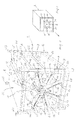
- the present tape reel assembly 1 essentially comprises a frame 2, a tape reel 3 rotatably supported in the frame 2, and a coil 4 wound from a metal tape 5 on the tape reel 3. It should be noted that the reel 4 can also consist of other material tapes.
- the frame 2 comprises two in the longitudinal direction of the band reel assembly 1 opposite, each held on a frame 6 side wall parts 7, in which the longitudinal axis 8 of the band reel 3 is rotatably mounted.
- bearing parts 10 are preferably arranged on the longitudinal axis 8, which are each preferably held in upwardly opening, circular cutouts 9 of the side wall parts 7 in that an annular circumferential groove 11 of each bearing part 10 surrounds the edge region of the respective cutout 9 of the corresponding side wall 7 overlaps.
- FIG. 1 only the bearing part 10, the circumferential groove 11 and the cutout 9 of the front side wall part 7 are shown.
- the corresponding elements of the rear side wall part 7 are formed accordingly. In this way, it is ensured that the band reel 3 together with the bearing parts 10 and the longitudinal axis 8 can be lifted out of the cutouts 9 upwards, for example, manually out of the frame 2.
- a plurality, preferably six guide slots 12 are provided, of which each two opposite in the longitudinal direction of the tape reel 2. In this way it is ensured that in each case a pressure roller 14 is held radially displaceable in a pair of longitudinally opposite guide slots 12 of the two side wall parts 7.
- Each longitudinal axis 13 projects with its end regions beyond its associated side wall parts 7 outwards to the sides facing away from the pressure roller 14.
- Each longitudinal axis 13 is preferably associated along a imaginary extension of the corresponding guide slot 12 radially inwardly a retaining bolt 15, which is fixed in the corresponding side wall part 7 and protrudes to the tape reel 3 opposite side of the side wall part 7 to the outside.
- the illustrated retaining bolts may be arranged radially outside the longitudinal axes of the pressure rollers, which is then not in the spring parts to tension springs, but to compression springs.
- the spring parts and other energy storage are conceivable.
- a handwheel 17 can be pushed in a rotationally fixed manner to at least one end of the longitudinal axis 8 of the band reel 3 that projects beyond a side wall part 7, so that the band reel 3 can be turned manually.
- the frame 2 on its upper side, on which the wound on the coil 4 metal strip 5 can be removed, in the transverse direction, ie, in the direction of the longitudinal axis 8 extending removal opening 18.
- the removal opening 18 joins in the removal direction 25 of the metal strip 5 as seen in a plate-shaped cover member 19, which is part of a cover unit 30 which is detachably arranged on the upper side of the frame 2.
- the cover unit 30 rests on angle parts 29, which are fastened to the frame 2.
- a plate-shaped bottom part 26, which closes the space below the lower pressure rollers 14 downwards, is preferably arranged on the frame 2 and underneath the band reel 3.
- the tape reel 3, z. B. after unwinding of the metal strip 5 and after the removal of the cover unit 30, are lifted up from the frame 2.
- the cutouts 9 in the side wall parts 7 are opened upward in the manner already mentioned, such that the longitudinal axis 8 can preferably be removed together with the bearing parts 10 from the cutouts 9.
- the upper openings of the cutouts 9 are larger than the diameter of the bottoms of the circumferential grooves 11 of the bearing parts 10.
- the upper pinch rollers 14 can be moved completely out of the area of the tape reel 3 against the force of the spring parts 16, at least one of the guide slots 12 assigned to these upper pinch rollers 14 has the opposite one Side wall parts 7 a from the outer end of the guide slot 12 extending downward bending region 31, in which the over the side wall portions 7 protruding free end portions of the longitudinal axes 13 of the upper pinch rollers 14 from the guide slot 12 are movable downwards and locked.
- Other locking devices for the longitudinal axes 13 of said longitudinal axes 13 are conceivable.
- the expediently rectangular frame 6 has on each side preferably two upwardly and upwardly projecting post parts 22, wherein the upper ends of the post parts 22 each have receiving parts 23 in which the lower ends of the post parts 22 '(FIG. FIG. 3 ) of a further frame 2 'of another band reel assembly 1' can be used, which can be arranged above the lower band reel assembly 1.
- the said post parts 22 project respectively downwards over transverse struts 28 fastened to them, so that for raising, lowering and transporting the band reel assembly 1 under the transverse struts 22 opposite the longitudinal axis 8 and extending transversely to the longitudinal axis 8, for example the lifting arms of a forklift or another lifting device can be inserted.
- the already mentioned bottom plate 26 rests on the cross struts 26 or is fixed or integrally connected thereto.
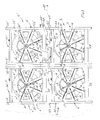
- a plurality of lower band reel assemblies 1 and upper Bandhaspelanordonne 1 'in rows next to and above each other are arranged.
- a Bandhaspelan whatsoever 1 is arranged below a Bandhaspelan whatsoever 1 ', the lower ends of their post parts 22' engage in the receiving parts 23 of the lower band reel assembly 1.
- a removal channel 27 formed by seen in the removal direction 25 each unwound from the coil 4 a rear band reel assembly 1 metal strip 5 can be pushed by turning the band reel 3 in each case in the removal direction 25 next front Bandhaspelan kann 1.
- a metal band 5 'of an upper band reel assembly 1' can be unwound from the coil 4 'by rotating the band reel 3' so that it slides below the band reel 3 'due to its inherent rigidity over the bottom part 26' in the withdrawal direction 25 and subsequently over the Bottom part 26 'of each adjacent in the removal direction 25 Bandhaspelan angel 1' is pushed.
- An advantage here is that both the metal strip 5 'taken from an upper band reel assembly 1' and the metal band 5 taken from a lower reel assembly 1 are transported substantially to a plane in which the respective processing takes place. Details of FIG. 3 already related to the FIGS. 1 and 2 are explained in the appropriate way.
Landscapes
- Engineering & Computer Science (AREA)
- Mechanical Engineering (AREA)
- Storage Of Web-Like Or Filamentary Materials (AREA)
Applications Claiming Priority (1)
| Application Number | Priority Date | Filing Date | Title |
|---|---|---|---|
| DE102013106274.1A DE102013106274A1 (de) | 2013-06-17 | 2013-06-17 | Bandhaspelanordnung zum Auf- und/oder Abwickeln eines Metallbandes |
Publications (2)
| Publication Number | Publication Date |
|---|---|
| EP2829333A1 true EP2829333A1 (fr) | 2015-01-28 |
| EP2829333B1 EP2829333B1 (fr) | 2017-05-03 |
Family
ID=50933019
Family Applications (1)
| Application Number | Title | Priority Date | Filing Date |
|---|---|---|---|
| EP14172015.1A Active EP2829333B1 (fr) | 2013-06-17 | 2014-06-11 | Enrouleur de feuillard pour l'enroulement et/ou le déroulement d'une bande métallique |
Country Status (2)
| Country | Link |
|---|---|
| EP (1) | EP2829333B1 (fr) |
| DE (1) | DE102013106274A1 (fr) |
Cited By (2)
| Publication number | Priority date | Publication date | Assignee | Title |
|---|---|---|---|---|
| CN111515266A (zh) * | 2020-05-28 | 2020-08-11 | 赵青山 | 一种合金线材卷绕方法 |
| CN112252016A (zh) * | 2020-09-27 | 2021-01-22 | 湖南煌丽箱包皮具有限公司 | 一种箱包面料裁切机 |
Citations (6)
| Publication number | Priority date | Publication date | Assignee | Title |
|---|---|---|---|---|
| US2725104A (en) * | 1951-06-15 | 1955-11-29 | Kaiser Aluminium Chem Corp | Coiling apparatus |
| DE2158721A1 (de) * | 1971-11-26 | 1973-05-30 | Indramat Gmbh | Bandhaspel mit gesteuerten andrueckrollen |
| DE2264587A1 (de) * | 1972-03-24 | 1974-05-16 | Kampf Maschf Erwin | Aufwickelvorrichtung fuer baender oder folien |
| DE2613453A1 (de) * | 1976-03-30 | 1977-10-13 | Bernhard Bruene | Wickelmaschine fuer folien |
| EP0391135A2 (fr) * | 1989-04-05 | 1990-10-10 | Sms Schloemann-Siemag Aktiengesellschaft | Procédé pour enrouler des bandes |
| DE102009029918A1 (de) | 2009-04-09 | 2010-10-14 | Hpl-Neugnadenfelder Maschinenfabrik Gmbh | Anwickelhilfe, Bandhaspel und Walzvorrichtung |
-
2013
- 2013-06-17 DE DE102013106274.1A patent/DE102013106274A1/de not_active Withdrawn
-
2014
- 2014-06-11 EP EP14172015.1A patent/EP2829333B1/fr active Active
Patent Citations (6)
| Publication number | Priority date | Publication date | Assignee | Title |
|---|---|---|---|---|
| US2725104A (en) * | 1951-06-15 | 1955-11-29 | Kaiser Aluminium Chem Corp | Coiling apparatus |
| DE2158721A1 (de) * | 1971-11-26 | 1973-05-30 | Indramat Gmbh | Bandhaspel mit gesteuerten andrueckrollen |
| DE2264587A1 (de) * | 1972-03-24 | 1974-05-16 | Kampf Maschf Erwin | Aufwickelvorrichtung fuer baender oder folien |
| DE2613453A1 (de) * | 1976-03-30 | 1977-10-13 | Bernhard Bruene | Wickelmaschine fuer folien |
| EP0391135A2 (fr) * | 1989-04-05 | 1990-10-10 | Sms Schloemann-Siemag Aktiengesellschaft | Procédé pour enrouler des bandes |
| DE102009029918A1 (de) | 2009-04-09 | 2010-10-14 | Hpl-Neugnadenfelder Maschinenfabrik Gmbh | Anwickelhilfe, Bandhaspel und Walzvorrichtung |
Cited By (4)
| Publication number | Priority date | Publication date | Assignee | Title |
|---|---|---|---|---|
| CN111515266A (zh) * | 2020-05-28 | 2020-08-11 | 赵青山 | 一种合金线材卷绕方法 |
| CN111515266B (zh) * | 2020-05-28 | 2021-02-05 | 三铃制线(东莞)有限公司 | 一种合金线材卷绕方法 |
| CN112252016A (zh) * | 2020-09-27 | 2021-01-22 | 湖南煌丽箱包皮具有限公司 | 一种箱包面料裁切机 |
| CN112252016B (zh) * | 2020-09-27 | 2023-04-28 | 肥东国喜箱包有限公司 | 一种箱包面料裁切机 |
Also Published As
| Publication number | Publication date |
|---|---|
| DE102013106274A1 (de) | 2014-12-18 |
| EP2829333B1 (fr) | 2017-05-03 |
Similar Documents
| Publication | Publication Date | Title |
|---|---|---|
| EP2516081B1 (fr) | Support pour bobine métallique et dispositifs équipés d'un tel support | |
| EP0281942A1 (fr) | Machine d'enlèvement de fil | |
| DE9218853U1 (de) | Wickelspule zur Herstellung eines Gebindes mit langgestrecktem Wickelgut | |
| WO2012098001A2 (fr) | Bobine destinée à recevoir un produit à enrouler et système de séparation de bobine | |
| EP2605987B1 (fr) | Dispositif continu | |
| DE3809496A1 (de) | Ringwickelvorrichtung sowie verfahren zum aufwickeln von wickelgut zu wickelringen | |
| EP1215153A2 (fr) | Installation pour l'enroulement optimal et automatique de longueurs de tuyau | |
| EP2829333B1 (fr) | Enrouleur de feuillard pour l'enroulement et/ou le déroulement d'une bande métallique | |
| DE2101114A1 (de) | Abwickelhaspel fur Rollen flexiblen Bandmaterials | |
| DE102014001779A1 (de) | Vorrichtung zum Lagern von Filamentspulen | |
| AT517353A4 (de) | Biegewerkzeugspeicher | |
| DE102023203689A1 (de) | Abstützvorrichtung für einen spulenkörper | |
| EP1171725B1 (fr) | Dispositif de transport | |
| EP3291926B1 (fr) | Système, véhicule pour le convoyage de bobines et procédé de déchargement d'une bobine depuis une installation de bobinage | |
| DE19739520C2 (de) | Vorrichtung zum Wickeln eines dünnen flachen Leiterdrahts in Hochkantstellung | |
| DE102010054142B4 (de) | Anordnung und Verfahren zur Abnahme wenigstens eines Metallbandbundes von einem Haspeldorn einer Aufwickelhaspel | |
| EP3585529B1 (fr) | Appareil et methode de transport d'une bobine | |
| DE102017111335B4 (de) | Vorrichtung zum Transportieren einer Wickelwalze bei einem Vlieswickler | |
| DE2751264C3 (de) | Vorrichtung zur Erleichterung der Abnahme voller Spulen von Spindelbänken | |
| DE202010011441U1 (de) | Mastsystem | |
| EP1075446A1 (fr) | Dispositif pour manipuler une bobine dans une bobineuse | |
| DE19900086A1 (de) | Laminatbahnrolle | |
| DE19927921B4 (de) | Hürdenbrett für Bogendruckmaschinen | |
| DE3534172A1 (de) | Schleifband-speicher | |
| DE102011008639A1 (de) | Wickelhülse zum Haspeln von bandförmigen Produkten |
Legal Events
| Date | Code | Title | Description |
|---|---|---|---|
| 17P | Request for examination filed |
Effective date: 20140611 |
|
| AK | Designated contracting states |
Kind code of ref document: A1 Designated state(s): AL AT BE BG CH CY CZ DE DK EE ES FI FR GB GR HR HU IE IS IT LI LT LU LV MC MK MT NL NO PL PT RO RS SE SI SK SM TR |
|
| AX | Request for extension of the european patent |
Extension state: BA ME |
|
| PUAI | Public reference made under article 153(3) epc to a published international application that has entered the european phase |
Free format text: ORIGINAL CODE: 0009012 |
|
| R17P | Request for examination filed (corrected) |
Effective date: 20150428 |
|
| RBV | Designated contracting states (corrected) |
Designated state(s): AL AT BE BG CH CY CZ DE DK EE ES FI FR GB GR HR HU IE IS IT LI LT LU LV MC MK MT NL NO PL PT RO RS SE SI SK SM TR |
|
| GRAP | Despatch of communication of intention to grant a patent |
Free format text: ORIGINAL CODE: EPIDOSNIGR1 |
|
| RIC1 | Information provided on ipc code assigned before grant |
Ipc: B21C 47/06 20060101AFI20161027BHEP Ipc: B65H 18/26 20060101ALI20161027BHEP Ipc: B65H 75/00 20060101ALI20161027BHEP Ipc: B65H 18/02 20060101ALI20161027BHEP Ipc: B21C 47/32 20060101ALI20161027BHEP |
|
| INTG | Intention to grant announced |
Effective date: 20161123 |
|
| GRAJ | Information related to disapproval of communication of intention to grant by the applicant or resumption of examination proceedings by the epo deleted |
Free format text: ORIGINAL CODE: EPIDOSDIGR1 |
|
| GRAP | Despatch of communication of intention to grant a patent |
Free format text: ORIGINAL CODE: EPIDOSNIGR1 |
|
| INTC | Intention to grant announced (deleted) | ||
| GRAS | Grant fee paid |
Free format text: ORIGINAL CODE: EPIDOSNIGR3 |
|
| INTG | Intention to grant announced |
Effective date: 20170227 |
|
| GRAA | (expected) grant |
Free format text: ORIGINAL CODE: 0009210 |
|
| AK | Designated contracting states |
Kind code of ref document: B1 Designated state(s): AL AT BE BG CH CY CZ DE DK EE ES FI FR GB GR HR HU IE IS IT LI LT LU LV MC MK MT NL NO PL PT RO RS SE SI SK SM TR |
|
| REG | Reference to a national code |
Ref country code: GB Ref legal event code: FG4D Free format text: NOT ENGLISH |
|
| REG | Reference to a national code |
Ref country code: AT Ref legal event code: REF Ref document number: 889405 Country of ref document: AT Kind code of ref document: T Effective date: 20170515 Ref country code: CH Ref legal event code: EP |
|
| REG | Reference to a national code |
Ref country code: IE Ref legal event code: FG4D Free format text: LANGUAGE OF EP DOCUMENT: GERMAN |
|
| REG | Reference to a national code |
Ref country code: DE Ref legal event code: R096 Ref document number: 502014003611 Country of ref document: DE |
|
| REG | Reference to a national code |
Ref country code: NL Ref legal event code: MP Effective date: 20170503 |
|
| REG | Reference to a national code |
Ref country code: LT Ref legal event code: MG4D |
|
| PG25 | Lapsed in a contracting state [announced via postgrant information from national office to epo] |
Ref country code: GR Free format text: LAPSE BECAUSE OF FAILURE TO SUBMIT A TRANSLATION OF THE DESCRIPTION OR TO PAY THE FEE WITHIN THE PRESCRIBED TIME-LIMIT Effective date: 20170804 Ref country code: HR Free format text: LAPSE BECAUSE OF FAILURE TO SUBMIT A TRANSLATION OF THE DESCRIPTION OR TO PAY THE FEE WITHIN THE PRESCRIBED TIME-LIMIT Effective date: 20170503 Ref country code: ES Free format text: LAPSE BECAUSE OF FAILURE TO SUBMIT A TRANSLATION OF THE DESCRIPTION OR TO PAY THE FEE WITHIN THE PRESCRIBED TIME-LIMIT Effective date: 20170503 Ref country code: LT Free format text: LAPSE BECAUSE OF FAILURE TO SUBMIT A TRANSLATION OF THE DESCRIPTION OR TO PAY THE FEE WITHIN THE PRESCRIBED TIME-LIMIT Effective date: 20170503 Ref country code: NO Free format text: LAPSE BECAUSE OF FAILURE TO SUBMIT A TRANSLATION OF THE DESCRIPTION OR TO PAY THE FEE WITHIN THE PRESCRIBED TIME-LIMIT Effective date: 20170803 Ref country code: FI Free format text: LAPSE BECAUSE OF FAILURE TO SUBMIT A TRANSLATION OF THE DESCRIPTION OR TO PAY THE FEE WITHIN THE PRESCRIBED TIME-LIMIT Effective date: 20170503 |
|
| PG25 | Lapsed in a contracting state [announced via postgrant information from national office to epo] |
Ref country code: BG Free format text: LAPSE BECAUSE OF FAILURE TO SUBMIT A TRANSLATION OF THE DESCRIPTION OR TO PAY THE FEE WITHIN THE PRESCRIBED TIME-LIMIT Effective date: 20170803 Ref country code: IS Free format text: LAPSE BECAUSE OF FAILURE TO SUBMIT A TRANSLATION OF THE DESCRIPTION OR TO PAY THE FEE WITHIN THE PRESCRIBED TIME-LIMIT Effective date: 20170903 Ref country code: SE Free format text: LAPSE BECAUSE OF FAILURE TO SUBMIT A TRANSLATION OF THE DESCRIPTION OR TO PAY THE FEE WITHIN THE PRESCRIBED TIME-LIMIT Effective date: 20170503 Ref country code: NL Free format text: LAPSE BECAUSE OF FAILURE TO SUBMIT A TRANSLATION OF THE DESCRIPTION OR TO PAY THE FEE WITHIN THE PRESCRIBED TIME-LIMIT Effective date: 20170503 Ref country code: RS Free format text: LAPSE BECAUSE OF FAILURE TO SUBMIT A TRANSLATION OF THE DESCRIPTION OR TO PAY THE FEE WITHIN THE PRESCRIBED TIME-LIMIT Effective date: 20170503 Ref country code: LV Free format text: LAPSE BECAUSE OF FAILURE TO SUBMIT A TRANSLATION OF THE DESCRIPTION OR TO PAY THE FEE WITHIN THE PRESCRIBED TIME-LIMIT Effective date: 20170503 Ref country code: PL Free format text: LAPSE BECAUSE OF FAILURE TO SUBMIT A TRANSLATION OF THE DESCRIPTION OR TO PAY THE FEE WITHIN THE PRESCRIBED TIME-LIMIT Effective date: 20170503 |
|
| PG25 | Lapsed in a contracting state [announced via postgrant information from national office to epo] |
Ref country code: EE Free format text: LAPSE BECAUSE OF FAILURE TO SUBMIT A TRANSLATION OF THE DESCRIPTION OR TO PAY THE FEE WITHIN THE PRESCRIBED TIME-LIMIT Effective date: 20170503 Ref country code: DK Free format text: LAPSE BECAUSE OF FAILURE TO SUBMIT A TRANSLATION OF THE DESCRIPTION OR TO PAY THE FEE WITHIN THE PRESCRIBED TIME-LIMIT Effective date: 20170503 Ref country code: CZ Free format text: LAPSE BECAUSE OF FAILURE TO SUBMIT A TRANSLATION OF THE DESCRIPTION OR TO PAY THE FEE WITHIN THE PRESCRIBED TIME-LIMIT Effective date: 20170503 Ref country code: SK Free format text: LAPSE BECAUSE OF FAILURE TO SUBMIT A TRANSLATION OF THE DESCRIPTION OR TO PAY THE FEE WITHIN THE PRESCRIBED TIME-LIMIT Effective date: 20170503 Ref country code: RO Free format text: LAPSE BECAUSE OF FAILURE TO SUBMIT A TRANSLATION OF THE DESCRIPTION OR TO PAY THE FEE WITHIN THE PRESCRIBED TIME-LIMIT Effective date: 20170503 |
|
| REG | Reference to a national code |
Ref country code: DE Ref legal event code: R097 Ref document number: 502014003611 Country of ref document: DE |
|
| PG25 | Lapsed in a contracting state [announced via postgrant information from national office to epo] |
Ref country code: SM Free format text: LAPSE BECAUSE OF FAILURE TO SUBMIT A TRANSLATION OF THE DESCRIPTION OR TO PAY THE FEE WITHIN THE PRESCRIBED TIME-LIMIT Effective date: 20170503 Ref country code: IT Free format text: LAPSE BECAUSE OF FAILURE TO SUBMIT A TRANSLATION OF THE DESCRIPTION OR TO PAY THE FEE WITHIN THE PRESCRIBED TIME-LIMIT Effective date: 20170503 |
|
| PLBE | No opposition filed within time limit |
Free format text: ORIGINAL CODE: 0009261 |
|
| STAA | Information on the status of an ep patent application or granted ep patent |
Free format text: STATUS: NO OPPOSITION FILED WITHIN TIME LIMIT |
|
| REG | Reference to a national code |
Ref country code: IE Ref legal event code: MM4A |
|
| REG | Reference to a national code |
Ref country code: FR Ref legal event code: ST Effective date: 20180228 |
|
| 26N | No opposition filed |
Effective date: 20180206 |
|
| PG25 | Lapsed in a contracting state [announced via postgrant information from national office to epo] |
Ref country code: LU Free format text: LAPSE BECAUSE OF NON-PAYMENT OF DUE FEES Effective date: 20170611 Ref country code: IE Free format text: LAPSE BECAUSE OF NON-PAYMENT OF DUE FEES Effective date: 20170611 |
|
| PG25 | Lapsed in a contracting state [announced via postgrant information from national office to epo] |
Ref country code: SI Free format text: LAPSE BECAUSE OF FAILURE TO SUBMIT A TRANSLATION OF THE DESCRIPTION OR TO PAY THE FEE WITHIN THE PRESCRIBED TIME-LIMIT Effective date: 20170503 Ref country code: FR Free format text: LAPSE BECAUSE OF NON-PAYMENT OF DUE FEES Effective date: 20170703 |
|
| REG | Reference to a national code |
Ref country code: BE Ref legal event code: MM Effective date: 20170630 |
|
| PG25 | Lapsed in a contracting state [announced via postgrant information from national office to epo] |
Ref country code: BE Free format text: LAPSE BECAUSE OF NON-PAYMENT OF DUE FEES Effective date: 20170630 |
|
| PG25 | Lapsed in a contracting state [announced via postgrant information from national office to epo] |
Ref country code: MT Free format text: LAPSE BECAUSE OF FAILURE TO SUBMIT A TRANSLATION OF THE DESCRIPTION OR TO PAY THE FEE WITHIN THE PRESCRIBED TIME-LIMIT Effective date: 20170503 |
|
| GBPC | Gb: european patent ceased through non-payment of renewal fee |
Effective date: 20180611 |
|
| PG25 | Lapsed in a contracting state [announced via postgrant information from national office to epo] |
Ref country code: GB Free format text: LAPSE BECAUSE OF NON-PAYMENT OF DUE FEES Effective date: 20180611 |
|
| PG25 | Lapsed in a contracting state [announced via postgrant information from national office to epo] |
Ref country code: HU Free format text: LAPSE BECAUSE OF FAILURE TO SUBMIT A TRANSLATION OF THE DESCRIPTION OR TO PAY THE FEE WITHIN THE PRESCRIBED TIME-LIMIT; INVALID AB INITIO Effective date: 20140611 Ref country code: MC Free format text: LAPSE BECAUSE OF FAILURE TO SUBMIT A TRANSLATION OF THE DESCRIPTION OR TO PAY THE FEE WITHIN THE PRESCRIBED TIME-LIMIT Effective date: 20170503 |
|
| PG25 | Lapsed in a contracting state [announced via postgrant information from national office to epo] |
Ref country code: CY Free format text: LAPSE BECAUSE OF FAILURE TO SUBMIT A TRANSLATION OF THE DESCRIPTION OR TO PAY THE FEE WITHIN THE PRESCRIBED TIME-LIMIT Effective date: 20170503 |
|
| PG25 | Lapsed in a contracting state [announced via postgrant information from national office to epo] |
Ref country code: MK Free format text: LAPSE BECAUSE OF FAILURE TO SUBMIT A TRANSLATION OF THE DESCRIPTION OR TO PAY THE FEE WITHIN THE PRESCRIBED TIME-LIMIT Effective date: 20170503 |
|
| PG25 | Lapsed in a contracting state [announced via postgrant information from national office to epo] |
Ref country code: TR Free format text: LAPSE BECAUSE OF FAILURE TO SUBMIT A TRANSLATION OF THE DESCRIPTION OR TO PAY THE FEE WITHIN THE PRESCRIBED TIME-LIMIT Effective date: 20170503 |
|
| PG25 | Lapsed in a contracting state [announced via postgrant information from national office to epo] |
Ref country code: PT Free format text: LAPSE BECAUSE OF FAILURE TO SUBMIT A TRANSLATION OF THE DESCRIPTION OR TO PAY THE FEE WITHIN THE PRESCRIBED TIME-LIMIT Effective date: 20170503 |
|
| PG25 | Lapsed in a contracting state [announced via postgrant information from national office to epo] |
Ref country code: AL Free format text: LAPSE BECAUSE OF FAILURE TO SUBMIT A TRANSLATION OF THE DESCRIPTION OR TO PAY THE FEE WITHIN THE PRESCRIBED TIME-LIMIT Effective date: 20170503 |
|
| REG | Reference to a national code |
Ref country code: DE Ref legal event code: R081 Ref document number: 502014003611 Country of ref document: DE Owner name: LERCHENMUELLER SPENGLEREI UND FLACHDACHBAU GMB, DE Free format text: FORMER OWNER: LERCHENMUELLER, MARKUS, 87452 ALTUSRIED, DE |
|
| REG | Reference to a national code |
Ref country code: AT Ref legal event code: PC Ref document number: 889405 Country of ref document: AT Kind code of ref document: T Owner name: LERCHENMUELLER SPENGLEREI UND FLACHDACHBAU GMBH, DE Effective date: 20221007 |
|
| REG | Reference to a national code |
Ref country code: DE Ref legal event code: R082 Ref document number: 502014003611 Country of ref document: DE Representative=s name: MITSCHERLICH, PATENT- UND RECHTSANWAELTE PARTM, DE Ref country code: DE Ref legal event code: R082 Ref document number: 502014003611 Country of ref document: DE Representative=s name: MITSCHERLICH PARTMBB, DE |
|
| PGFP | Annual fee paid to national office [announced via postgrant information from national office to epo] |
Ref country code: CH Payment date: 20250701 Year of fee payment: 12 |
|
| REG | Reference to a national code |
Ref country code: CH Ref legal event code: U11 Free format text: ST27 STATUS EVENT CODE: U-0-0-U10-U11 (AS PROVIDED BY THE NATIONAL OFFICE) Effective date: 20260701 |
|
| PGFP | Annual fee paid to national office [announced via postgrant information from national office to epo] |
Ref country code: DE Payment date: 20260518 Year of fee payment: 13 |
|
| PGFP | Annual fee paid to national office [announced via postgrant information from national office to epo] |
Ref country code: AT Payment date: 20260618 Year of fee payment: 13 |